Design and Manufacture of Eccentric Planetary Gear Drive ...
4
The 4th International Conference on Design Engineering and Science, ICDES 2017 Aachen, Germany, September 17-19, 2017 Copyright © 2017, The Organizing Committee of the ICDES 2017 161 Design and Manufacture of Eccentric Planetary Gear Drive with Hydraulic Motor (Power Transmission Efficiency of Trial Gear Reducer) Keiji SONODA* 1 , Hidenori HIRAI* 2 , Maki SONODA* 1 and Kazuki TAKENOUCHI* 3 *1 Faculty of Future Industry, Happy Science University 4427-1 Hitotsumatsu Hei, Chosei-mura, Chosei-gun 299-4325, JAPAN [email protected] *2 Development Division, Chikusui Canicom Inc. 90-1 Fukumasu, Yoshii-machi, Ukiha-city 839-1396, JAPAN [email protected] *3 Faculty of Design, Kyushu University 4-9-1 Shiobaru, Minami-ku, Fukuoka-city 815-8540, JAPAN [email protected] Abstract An eccentric planetary gear drive with hydraulic motor was developed, specifications of which were determined based on its service conditions as required for a relatively small-sized crawler-type conveyer for agriculture-use. The gear train was originally designed by arranging gears, including an eccentric planetary gear, and manufactured. Measured efficiency of power transmission of the gear drive by means of the torque balance method under quasi-steady state was approx. 0.92 at the highest, lubricated with hypoid gear oil, promising availability of the newly developed reduction gear drive in practical use. Also shown in operating test was a relatively high efficiency of 0.87 in speed increasing conditions. Keywords: design, manufacture, planetary gear drive, eccentric gear, efficiency, power transmission 1 Introduction Various types of gear drive are employed to increase or decrease speed for various machinery and transportation such as robot and automobiles. In this study, an eccentric planetary gear drive with hydraulic motor was developed for irrigation, drainage and reclamation, featuring a simple and robust device with fewer components. For the requirement, a gear arrangement based on planetary gear with an eccentric gear is adopted and a detailed design is carried out. A prototype gear drive is tested to certify its performance. 2 Design concepts of the gear drive The gear drive to be developed in this study is for a commercial crawler-type conveyer of relatively small-size used for agriculture-use. In addition to the usual requirements of high efficiency with high power for its light weight and small size, easy operation and maintenance is necessary as such a machinery tends to be handled roughly in the field regardless of weather. Also from a view point of mass production, less material and manufacturing costs, than used in a standard manufacturing environment and fewer components, and easy assembling are always essential. 3 Mechanism and principal features Given that the gear drive developed here is planned to be attached to a crawler-type conveyer, it is preferable that this be an integral structure of a hydraulic motor and a speed decreasing device more than a power transmission device with a gear train driven by an engine. The hydraulic motor adopted here, a piston-type with swash plate, requires reduction of speed by 1/20, which is in an application range of planetary gears but relatively large for a single reduction. Figure 1 (a) and (b) illustrate the outlook and the schematic drawing of the proposed eccentric planetary gear drive, which consists of an external gear assembled by two planetary gears G 1 and G 3 and internal gears of two independent gears [1], a type of differential gears. By replacing the eccentric planetary gear drive with a hydraulic engine for the conventional engine and reduction gear system, the number of parts can be reduced by 30%. The revolution of the input shaft, an eccentric shaft, EPGD (a) Cut model of EPGD (b) Schematic drawing (c) Gearing at each stage (CAD model) Fig. 1 Eccentric planetary gear drive
Transcript of Design and Manufacture of Eccentric Planetary Gear Drive ...
The 4th International Conference on Design Engineering and Science, ICDES 2017 Aachen, Germany, September 17-19, 2017
Copyright © 2017, The Organizing Committee of the ICDES 2017
161
Design and Manufacture of Eccentric Planetary Gear Drive with Hydraulic Motor (Power Transmission Efficiency of Trial Gear Reducer)
Keiji SONODA*1, Hidenori HIRAI*2, Maki SONODA*1 and Kazuki TAKENOUCHI*3
*1 Faculty of Future Industry, Happy Science University 4427-1 Hitotsumatsu Hei, Chosei-mura, Chosei-gun 299-4325, JAPAN [email protected]
*2 Development Division, Chikusui Canicom Inc. 90-1 Fukumasu, Yoshii-machi, Ukiha-city 839-1396, JAPAN [email protected]
*3 Faculty of Design, Kyushu University 4-9-1 Shiobaru, Minami-ku, Fukuoka-city 815-8540, JAPAN [email protected]
Abstract
An eccentric planetary gear drive with hydraulic motor was developed, specifications of which were determined based on its service conditions as required for a relatively small-sized crawler-type conveyer for agriculture-use. The gear train was originally designed by arranging gears, including an eccentric planetary gear, and manufactured. Measured efficiency of power transmission of the gear drive by means of the torque balance method under quasi-steady state was approx. 0.92 at the highest, lubricated with hypoid gear oil, promising availability of the newly developed reduction gear drive in practical use. Also shown in operating test was a relatively high efficiency of 0.87 in speed increasing conditions. Keywords: design, manufacture, planetary gear drive, eccentric gear, efficiency, power transmission
1 Introduction Various types of gear drive are employed to
increase or decrease speed for various machinery and transportation such as robot and automobiles.
In this study, an eccentric planetary gear drive with hydraulic motor was developed for irrigation, drainage and reclamation, featuring a simple and robust device with fewer components. For the requirement, a gear arrangement based on planetary gear with an eccentric gear is adopted and a detailed design is carried out. A prototype gear drive is tested to certify its performance.
2 Design concepts of the gear drive
The gear drive to be developed in this study is for a commercial crawler-type conveyer of relatively small-size used for agriculture-use. In addition to the usual requirements of high efficiency with high power for its light weight and small size, easy operation and maintenance is necessary as such a machinery tends to be handled roughly in the field regardless of weather. Also from a view point of mass production, less material and manufacturing costs, than used in a standard manufacturing environment and fewer components, and easy assembling are always essential.
3 Mechanism and principal features Given that the gear drive developed here is planned to
be attached to a crawler-type conveyer, it is preferable that this be an integral structure of a hydraulic motor and a speed decreasing device more than a power transmission device with a gear train driven by an engine. The hydraulic motor adopted here, a piston-type with swash plate, requires reduction of speed by 1/20, which is in an application range of planetary gears but relatively large for a single reduction.
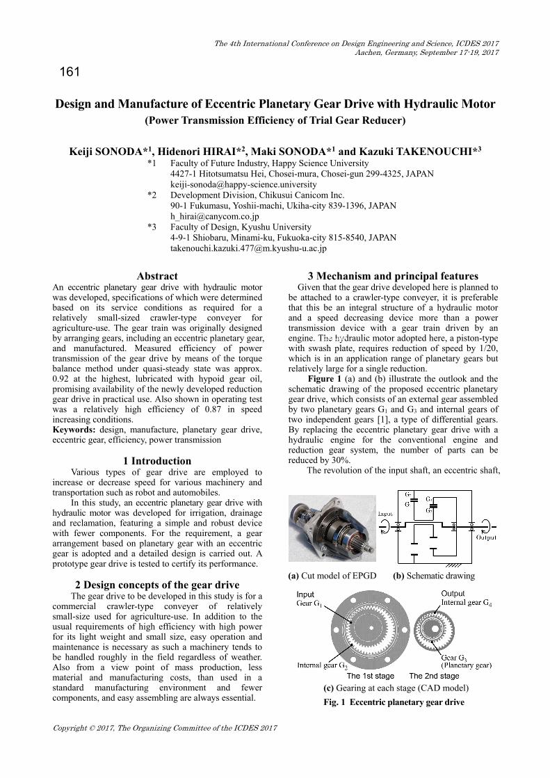
Figure 1 (a) and (b) illustrate the outlook and the schematic drawing of the proposed eccentric planetary gear drive, which consists of an external gear assembled by two planetary gears G1 and G3 and internal gears of two independent gears [1], a type of differential gears. By replacing the eccentric planetary gear drive with a hydraulic engine for the conventional engine and reduction gear system, the number of parts can be reduced by 30%.
The revolution of the input shaft, an eccentric shaft,
EPGD
(a) Cut model of EPGD (b) Schematic drawing
(c) Gearing at each stage (CAD model)
Fig. 1 Eccentric planetary gear drive

is transmitted to the gear G1 in Fig. 1(b) as its revolution, causing also the rotation of G1 corresponding to the difference in number of teeth to G2 by Z2 –Z1. This rotation is next transmitted to G3 which is a single component with G1, and finally its superposed rotation and revolution together give G4 the rotation, namely, the output.
The reduction ratio i = 20.7 in Eq. (1) is directly estimated by integrating all the gear engagements and the superposition method is a useful alternative [1],
)ZZZZ(ZZ 32412112 i ...................... (1)
where 1 and 2 are the angular velocities of input and output shafts, respectively.
Table 1 lists the primary specifications of EPGD developed in this study; the difference of number of teeth between the external and the internal gears is 7 on the two stages and a small amount of profile shifting is adopted to eliminate any interferences from gear engagement.
4 Performance test of developed gear drive
4.1 Measurement method A performance test of EPGD was carried out by
use of the torque balance method [2] in which static input torque T1 and output torque T2 were loaded using weights on two 400 pulleys attached to its input and output shaft ends, respectively. Keeping T2 constant, T1 on the input shaft is gradually increased. When the input torque exceeds a critical value, the output shaft comes to revolve. The magnitudes of torque at the critical condition are substituted to Eq. (2) to evaluate the efficiency of transmission, . This method gives a simple way to estimate in a steady operation.
1122 TT ................................................... (2)
4.2 Lubrication The performance of the trial eccentric planetary
gear drive was measured with five types of lubricant in bath lubrication: they are Oil A (Spindle oil, [10]), Oil B (Cylindrical gear oil, [63]), Oil C (Hypoid gear oil, [199]), Oil D (HW46, [48]), Oil E (SN/CF 5W-40, [94]), where the number in the square brackets indicates the dynamic viscosity in the unit of mm2/s at 40°C of each oil. The latter two oils were expected to be used in a practical application. 4.3 Experimental results and discussion
Figure 2 shows the test results in a speed decreasing condition. The gear drive gives an almost constant efficiency in the region of input torque greater than 1Nm. The efficiencies are almost the same with the two oils, Oil D and E, expected for practical use in wide operating conditions of input torque. Also in the figure, efficiencies are compared when other types of Oil A, B and C are used, clearly showing the importance of appropriate selection of oil for high performance. With Oil C, hypoid gear oil including various additives, the efficiency 0.92 is the highest improved by 3 percent compared to those with Oil D and E.
Shown in Fig. 3 is the efficiency of the EPGD used in a speed increasing condition by exchanging the input and output operations. The efficiency was acceptably high over a wide range of input torque and the highest efficiency of 0.87 was almost the same as that of the speed reduction obtained when Oil C is used. The results suggest EPGD developed in this study is also available in speed increase condition.
5 Theoretical efficiency of EPGD
It is still difficult to estimate the theoretical efficiency of a gear drive in power transmission with sufficient accuracy. This difficulty mainly arises from difficulty in precise estimation of magnitude of friction coefficient between teeth working under constantly changing normal load, contact stress and the sliding speed in meshing besides the deformation of teeth under
0 0.5 1 1.5 20.2
0.4
0.6
0.8
Input Torque T [Nm]
Oil A (spindle oil)Oil B (cylindrical gear oil)Oil C (hypoid gear oil)Oil D (hydraulic fluid HW46)Oil E (engine oil SN/CF 5W−40)
Fig. 2 Efficiency of trial EPGD in speed reduction
0 10 20 30 40
0.2
0.4
0.6
0.8
Input Torque T [Nm]
Oil A (spindle oil)Oil C (hypoid gear oil)
Fig. 3 Efficiency of trial EPGD in speed increase
Table 1 Specifications of trial gear reducer
Stage of gearing 1st stage 2nd stage Type of gear Ext. Int. Ext. Int.
Term and symbol Z1 Z2 Z3 Z4 Module, m 1.5 1.5 Number of teeth 42 49 31 38 Pressure angle, 20° Helix angle, 0° Coeff. profile shifting, x -0.1 +0.2 -0.1 +0.2Center distance, A 5.25 5.25 Pitch diameter, D 63.0 73.50 46.50 57.00Base circle diameter, dg 59.20 71.10 49.20 54.60Outside diameter, dk 58.95 77.85 42.45 61.35Root diameter, dr 59.95 77.85 42.45 61.35Backlash, c0 (0.2) Approach contact ratio, a 0.78 0.76 Recess contact ratio, r 0.93 1.01 Total contact ratio, t 1.72 1.76 Face width, b 15 15 Reduction ratio, i 20.73 Note Material: JIS SCM415 Heat treatment: Case carburized Surface finish: Gear shaped by pinion cutter Interference: Interference occurred by a trimming

load is ignored. In order to solve this problem provisionally, the
friction coefficient e at properly designated points on the tooth face is adopted as the representative value of . For the sake of simple estimation, the deformation of gear teeth is to be ignored.
EPGD developed by the authors works under the power input to Gear 1 in Fig. 1 and the power output from Gear 4 through the drive shaft; its reduction mechanism consists of two stages. Here, in a usual way to derive the theoretical efficiency of this kind of multi-stage mechanism [3], the mechanism of this gear drive is divided into two stages and the efficiency in each stage of meshing between the internal and external gears derived individually as 1st and 2nd. The overall efficiency CB is estimated by combining the two efficiencies. Figure 4 illustrates the schematic diagram of reduction mechanism of the eccentric planetary gear drive for the derivation of theoretical efficiency below. 5.1 Theoretical efficiency in single gearing
The efficiencies in power transmission in meshing between the pair of external and internal gears in Figs. 5 and 6 is estimated as bellows [5] in approach contact and recess contact, A and B respectively:
)/(sincos
)/1/1(1
)/(sincos
)/1/1(1
1mean,1e
21mean,1eB
1mean,2e
21mean,2eA
R
RRR
RR
........... (3)
where mean is the characteristic length between the pitch point and the contact point determined the next formulae.
2/)sinαsin(
2/)sinsin(
k2k22mean,2
1k1k1mean,1
RR
RR ................... (4)
and e is the coefficient of friction at the point mean distant from the pitch point.
The efficiency between the external gear and the internal gear is finally determined by the next formula.
RA
RRAA1st
............................................ (5)
where A and R are the meshing ratio in approach and recess contact conditions, respectively.
cos
sin)sin(cos
)sin(sin
22
12k1
R
22
2k22
A
t
RRRt
RRR
................. (6)
where R1 and R2 are the pitch-circle radiuses, Rk1 and Rk2 are the tip-circle radiuses, is the meshing pressure angle, and t is the circular pitch, t = m.
In the same manners, the efficiency in power transmission in the 2nd stage, 2nd. 5.2 Theoretical efficiency of EPGD
EPGD in the authors’ development study runs by conversing the power input to the arm C into the power output from the internal gear B in the fixed internal gear A as shown in Fig. 4. In the estimation of the theoretical
efficiency of this kind of multi-stage mechanism, a popular manner was employed by dividing the whole behavior of transmission into two stages as below, manner which is often used for a complicated gear mechanism.
As the first step, power input to the internal gear B and power output from the internal gear A is considered under condition that the carrier C is fixed. In this condition, the gear B rotating counter-clock-wise drives the gear A also counter-clock-wise in the same direction to the gear B: the moment of force TB loaded on the gear B is negative and then the positive moment of force TA is required to maintain an equilibrium state of steady motion. The efficiency in power transmission 0, the reference efficiency, is defined and TB is derived as
)()()()(0 BBAABBAA nTnTTT ........... (7)
000B )()( ABAA TunnTT
where u0 = nA/nB = (Z1 Z4) / (Z2 Z3). In order to keep the EPGD in a stationary state
under the above pair of moment of force, TA and TB, the
Fig. 4 Schematic of eccentric planetary gear drive
Fig. 5 Meshing of a gear pair [4]
(a) Approach contact (b) Recess contact
Fig. 6 Forces acting between teeth [3]

clock-wise moment of force TC in next formula is required to be added on the carrier C.
ABA Tu
TTT )1()(0
0C
By adding further clock-wise rotation of the entire system back to the initial angular position of the external gear A, the overall operation is equivalent to the one where the gear A is fixed, that is the normal behavior of the drive. Keeping the above equilibrium of moment of force throughout the sequential operations, the carrier C makes clock-wise full turn with TC as an input and the internal gear B rotates by 11/u0 with TB as an output in counter-clock-wise direction. The theoretical efficiency in power transmission of this gear drive system is consequently determined by the next formula as the ratio of the output TB (11/u0) to the input TC1 [6],
00
00CB
1)/11(
u
u
T
uT
C
B ........................... (8)
where the reference efficiency 0 in the above equation is the combination of 1st and 2nd, the efficiencies of single gearing between an external and an internal gears in the first and the second stages, respectively, estimated in the previous chapter, as
2nd1st0 ...................................................... (9)
The theoretical efficiency in power transmission of this gear drive system EPGD is finally expressed by the next formula.
2nd1st0
0CB
1
u
u ......................................... (10)
5.3 Estimated theoretical efficiency and discussion By use of the expression of theoretical efficiency
derived in the previous section, the one of EPGD developed in this study was evaluated with the specifications in Table 1. In the calculation, the magnitude of friction coefficient was presumed as e = 0.1 considering that the gears of the prototype were shaped by pinion cutter without grinding and an insufficient fluid lubrication between the gear faces in a quasi-static condition in the experiment.
As listed in Table 2, the basic efficiencies in the 1st and the 2nd stages are 1st = 0.9991 and 2nd = 0.9982, respectively, giving the reference efficiency 0 = 0.9973 and finally the theoretical efficiency CB = 0.9493. Considering that additional loss caused by windage, friction in bearing and stirring of oil should be considered for a more precise estimation, the expression of the theoretical efficiency of EPGD and the estimated results are considered to be valid.
The estimated theoretical efficiencies under various values of friction coefficient e are summarized in Table 2. The results clearly show that the efficiency of gear device having a differential motion is in general strongly depends on the reference efficiency in each stage. Since the lubricant is one of the governing factors affecting the coefficient of friction, the importance of an appropriate selection of lubricating oil is suggested.
6 Conclusions A new eccentric planetary gear drive has been
developed with fewer components and less volume than a hydraulic motor and its performance was measured in a quasi-statistical condition.
1) The gear drive gives the highest efficiency max =
0.92 with the hypoid gear oil that has the highest viscosity among the tested oils with various additives. A satisfactory behavior in dynamic operating conditions, in addition, shows a possibility for further development.
2) The expression of the theoretical efficiency of EPGD is derived by dividing its operation into two stages.
3) The theoretical efficiency of the prototype developed in this study was estimated with presuming the magnitude of coefficient of friction e = 0.1. The estimation CB = 0.949 was considered to be valid compared to the experimental results with additional loss by friction and stirring resistance.
References [1] Ishibashi A. and Sonoda K., “Theoretical Efficiency
of Epicyclic Differential Gear Drives with High Reduction for Robot”, Proceedings of the 4th International Tribology Conf., (1994), pp.619-624.
[2] Ishibashi A., Sonoda K. and Isami S., “Theoretical Efficiencies of Planetary Gear Drives for Speed Increase and Reduction with Experimental Verification”, Proceedings of the 7th International Power Transmission and Gering Conf., (1996), pp.397-404.
[3] Ishibashi A., Sonoda K. and Hoyashita, S., “Estimation of Efficiency of Gear Drives with Complex Mechanism using Traction Coefficient Obtained by Disk Machine”, Proceedings of 6th International Congress on Tribology, (1993), pp.371-376.
[4] Ueno, T. et al., “Gear Engineering” (in Japanese), Kyoritsu Shuppan, (1982), p.73.
[5] Ishibashi A. and Sonoda K., “Planetary Traction Drives with High Efficiencies”, Proceedings of the JSME International Conference on Motion and Power Transmissions, (1991), pp.977-982.
[6] Wakuri A. et al., “Design and Manufacturing of Gears” (in Japanese), JSME, (1956), pp.228-232.
Received on December 28, 2016 Accepted on March 15, 2017
Table 2 Theoretical efficiency of EPGD
Friction coefficient
Theoretical efficiency Eq.(5) Eq.(5)’ Eq.(9) Eq.(10)
e 1st 2nd 0 CB 0.05 0.9995 0.9991 0.9986 0.974 0.08 0.9993 0.9986 0.9978 0.959 0.10 0.9991 0.9982 0.9973 0.949 0.20 0.9982 0.9964 0.9946 0.903 0.30 0.9973 0.9946 0.9918 0.861