Development of Guidelines for Triple Left and Dual Right-Turn Lanes
Design and Implementation of Slot Left-Turn Lanes on the Manitoba Highway Network
Brent Hartmann, P. Eng., Project Design Engineer, Manitoba Infrastructure and Transportation
Derek Durant, P. Eng., Senior Functional Design Engineer, Manitoba Infrastructure and Transportation
Paper prepared for presentation at the Geometric Design: Lessons Learned Session of the 2013 Conference of the Transportation Association of Canada Winnipeg, Manitoba

1
Provincial Trunk Highway (PTH) 12 in the City of Steinbach, Manitoba, is a 4-lane divided roadway. As it was originally designed to expressway standards, the medians are wide to provide appropriate separation of traffic. Making direct left turns from PTH 12 is problematic because the large intersection footprint results in poor sightlines when signalized and adds to driver confusion, with many drivers making left turns by passing opposing left-turn traffic on the right. The City of Steinbach has seen rapid growth over the past decade, and development along PTH 12 has necessitated the improvement of operations at several intersections.
Manitoba Infrastructure and Transportation (MIT) has begun implementing slot left-turn lanes in an attempt to remediate these issues. Three intersections in Steinbach have received this treatment over the past seven years and public reaction appears to be positive.
Proper selection of design speed and vehicle are crucial when designing slot left-turn lanes. Furthermore, signage and lane markings must be appropriate for both seasoned urban drivers and rural drivers who are unfamiliar with this form of channelization. The configuration and location of a raised divisional island must take into account maintenance (snow clearing) and emergency vehicle access. MIT has used the knowledge gained in designing, constructing and operating slot left-turns to refine the design for future applications.

1
1.0 Background
The City of Steinbach, Manitoba, is a community of about 14,000 people located approximately 50 km south-east of Winnipeg (Figures 1 and 2). Provincial Trunk Highway (PTH) 12 travels north-south through the community and is the main route from the residential areas in the south and east ends of the city to the major commercial developments in the north-west. PTH 12 also provides an essential link to the Trans Canada Highway, and to the City of Winnipeg. Because of its strategic location between Winnipeg and the U.S. Midwest, as well as having close access to the Trans Canada Highway, Steinbach is home to several commercial trucking firms. Figures 1 and 2 show Steinbach’s location in relation to Winnipeg and the Trans Canada Highway, and an overall city map.
Figure 1 Figure 2
The population of Steinbach has been growing at an average rate of about 4% per year over the past decade (compared to 0.7% for Manitoba as a whole), and commercial development along the PTH 12 corridor has increased substantially. Both developers and Manitoba Infrastructure and Transportation (MIT) have had to make improvements to the highway to ensure increasing volumes of turning traffic can be accommodated in a safe and efficient manner.
PTH 12 is a four-lane divided roadway as it enters Steinbach from the north and is classified as an expressway. Similar to most divided highways in Manitoba, it has a wide median of 23.0 m from inside edge-of-lane to inside edge-of-lane, which creates problems at intersections where the intersection footprint is very large and does not provide proper guidance

2
to the travelling public. Left turns are particularly problematic, as a common mistake by drivers is to carry out their left turn by passing opposing left-turn drivers on the right. This confuses drivers trying to make the correct manoeuvre and creates two additional conflict points. A preferred solution to this problem is to channelize the left-turn movements and move drivers to turn to the left of opposing traffic through the use of slot left-turn lanes. The Transportation Association of Canada’s (TAC) Geometric Design Guide for Canadian Roads lists several advantages to using slot left-turn lanes, including increased safety, defined turning paths and increased capacity of left-turn movements.1
2.0 Locations
The first slot left-turn lanes along PTH 12 (henceforth known as Location 1) were constructed in 2006 as part of intersection improvements for an access to a new commercial development adjacent to PTH 12. It was designed by a consultant working on behalf of the developer, and reviewed and approved by MIT. The posted speed limit along this section of PTH 12 is 70 km/hr. The original intersection was a simple median opening with access to a service road to the west (where the commercial development was built) and access to a gas station to the east. When completed, both northbound and southbound left-turn movements were handled by slot left-turn lanes. See Figure 4 (appended).
The second intersection (Location 2) on PTH 12 to receive a slot left-turn treatment was at Clearspring Road at the north end of Steinbach in 2009. This was the first intersection to receive a slot left-turn treatment that was entirely designed in-house by MIT. The intersection is located at the transition from an urban setting to rural. Prior to the intersection improvements, due to a lack of development along this section of PTH 12, the posted speed was 100 km/hr, but owing to increased development that occurred during the design and construction phases, the posted speed limit was reduced to 80 km/hr. As the four quadrants of the intersection are occupied by a commercial trucking company, two farm implement dealers and a bulk fuel depot, truck turning volumes approach 25% of all turning traffic. Clearspring Road was originally controlled by stop signs, while traffic on PTH 12 was unimpeded. Due to large volumes of PTH 12 traffic and insufficient gaps, the queuing of these trucks and subsequent delays created a situation with very impatient drivers. Signalization was proposed to alleviate driver frustration and slot left-turn lanes were introduced to reduce the number of incorrect driver manoeuvres. See Figure 5 (appended).
The third location (Location 3) where slot left-turn lanes are currently being constructed is situated on PTH 12 at Golfair Road, approximately midway between the other two intersections. The configuration of these intersection improvements were designed by a consultant. The improvements were initiated by the construction of a new large discount department store adjacent to an existing shopping centre on the west side of PTH 12. Golfair Road on the east side of PTH 12 provides access to Steinbach Airport where traffic volumes are
3
relatively low. This intersection is in close proximity to a 70 km/hr to 80 km/hr posted speed transition as traffic leaves Steinbach.
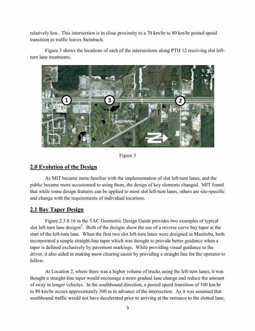
Figure 3 shows the locations of each of the intersections along PTH 12 receiving slot left-turn lane treatments.
Figure 3
2.0 Evolution of the Design
As MIT became more familiar with the implementation of slot left-turn lanes, and the public became more accustomed to using them, the design of key elements changed. MIT found that while some design features can be applied to most slot left-turn lanes, others are site-specific and change with the requirements of individual locations.
2.1 Bay Taper Design
Figure 2.3.8.16 in the TAC Geometric Design Guide provides two examples of typical slot left-turn lane designs2. Both of the designs show the use of a reverse curve bay taper at the start of the left-turn lane. When the first two slot left-turn lanes were designed in Manitoba, both incorporated a simple straight-line taper which was thought to provide better guidance when a taper is defined exclusively by pavement markings. While providing visual guidance to the driver, it also aided in making snow clearing easier by providing a straight line for the operator to follow.
At Location 2, where there was a higher volume of trucks using the left-turn lanes, it was thought a straight-line taper would encourage a more gradual lane change and reduce the amount of sway in longer vehicles. In the southbound direction, a posted speed transition of 100 km/hr to 80 km/hr occurs approximately 300 m in advance of the intersection. As it was assumed that southbound traffic would not have decelerated prior to arriving at the entrance to the slotted lane,

4
the length of the slot left-turn lane was based on a design speed of 120 km/hr and a 25:1 taper was used.
The design at Location 3 makes use of a curvilinear bay taper with a parallel auxiliary lane that curves into a slot lane at the intersection. It was determined that this was a better solution as it provided a long auxiliary lane for deceleration and storage, but reduced the costs associated with grading and paving a wide gore area that a straight taper would require.
2.2 Width of Slot Lane
With a range of widths identified in various geometric design guides, deciding on the appropriate width for a slot left-turn lane led to numerous discussions within MIT. On Manitoba’s highway network, although the standard for a through lane is 3.7 m wide, the standard for a left-turn lane is 4.0 m to provide the driver with more shy distance from adjacent high speed traffic. The channelization for the slot left-turn lane introduced two conflicting factors: the lane had to be narrow enough so that drivers do not perceive it as multiple lanes, but it had to be wide enough so that vehicles can manoeuvre around a disabled vehicle as well as provide access for emergency vehicles. The use of semi-mountable curbs providing lane definition helps with the latter during the summer, but the winter would provide its own challenge as the median and divisional islands would be used for snow storage.
At Location 1, the left-turn lanes were designed as 5.0 m wide, with an additional 0.6 m of width provided by the monolithic curb and gutter. When initially opened to the public, there were some cases of drivers mistaking the wide lane as two lanes and lined up side-by-side. This problem eventually alleviated itself as the public became more familiar with the operation of the intersection.
During the development of the design for the second intersection, the initial problems with the Location 1 were still fresh with MIT. The high design speed yielding a long left-turn lane, coupled with the gentle 25:1 taper, led to concerns that drivers may attempt to stack up adjacent to one-another in the slot left-turn lane. Due to these concerns, it was decided to narrow the lane to 4.1 m, with 0.3 m gutters provided on either side. As the intersection itself is significantly wider than that at Location 1, the perceived need for drivers to angle their vehicles in the slotted lane was reduced. MIT also developed new signage specifically showing the number of lanes for turning and through traffic.
Location 3 was designed with a 3.7 m wide parallel auxiliary lane that widens to 5.5 m in the channelized portion. This alternative variation for channelization appears to work as the 3.7 m auxiliary lane funnels a single lane into the slotted lane that is relatively short and requires longer vehicles to align themselves prior to entering the intersection.
5
2.3 Divisional Island
The design of the divisional islands for slot left-turn lanes is a critical component in providing proper guidance to the driver. They provide a means for separating the turning traffic from the through traffic, and force drivers to angle their vehicles properly prior to entering the intersection.
The first two locations made use of elongated teardrop shaped islands, which worked well with the straight taper design of the lanes. They were designed with semi-mountable curbing and a raised grass centre. The islands were offset from the median bullnose to provide guidance and a smooth turning path for vehicles entering the highway and as such, it would require significant effort on the driver’s part to enter the slot left-turn lane the wrong way.
Location 3 has divisional islands designed similar to those used for a right-turn-cutoff, however for turning left instead. It has been found that these work well to limit the size of the intersection’s footprint by aligning the vehicle in such a way that the start of the left turn is initiated within the slot left-turn lane. The islands will be finished with raked asphalt, and although this may not be as aesthetically pleasing, it will ease maintenance and snow clearing.
MIT has considered the use of painted islands to save cost, however their effectiveness in winter was questionable specifically due to Location 2’s semi-rural environment. It was also thought that painted islands would not provide a defined refuge area for pedestrians and would not provide a suitable location for placing signals.
2.4 Signage and Signalization
When the first slot left-turn was constructed at Location 1, only conventional signage was installed. This was, in part, due to the short length of the slot left-turn lanes which provided good visual clues of the intersection's layout and the fact that it was located in an area where it would be used mostly by local residents going to the grocery store or gas station. Although it appeared that there was a short period of driver confusion at the beginning of operation, through experience and familiarity, this apparent confusion dissipated and the intersection now operates as intended.
Due to the nature of businesses located at the northern limits of Steinbach, many are serviced by non-local drivers making deliveries. As the southbound slot left-turn lane started approximately 400 m from the intersection, there was a concern that drivers not knowing where and when they should change lanes would miss the lane entirely. For these reasons, MIT placed advanced warning signage for the left-turning traffic. Reaction to the signage was found to be positive.
Based on knowledge gained from the operation of the other two intersections with slot left-turn lanes, special signage was not developed for Location 3. Reasons for the omittance

6
included: 1) the intersection is located in close proximity to Location 1, 2) it is to be used mostly by local drivers familiar with slot left-turn lanes and 3) it is in a reduced speed zone.
Two of the three intersections are currently signalized and the third will be signalized in the final stages of construction. Intersection improvements combined with signalization has increased safety and improved the level of service for traffic entering PTH 12.
3.0 Future Implementations and Design Considerations
The reaction from both the public and City of Steinbach has been very positive towards the use of slot left-turn lanes. This has encouraged MIT to look at other intersections that could be improved in the same manner. Since the first two intersections were completed in Steinbach, improvements using a slot left-turn design have also been made to an intersection in Brandon, Manitoba. Based on the experience and knowledge gained by the implementation of three variations of lot left-turn lanes, MIT is in the process of developing standards for slot left-turn lanes for which a policy can be created.
7
References
1. Transportation Association of Canada, Geometric Design Guide for Canadian Roads – Part 2 (September 1999, updated December 2009), p. 2.3.8.22
2. Transportation Association of Canada, Geometric Design Guide for Canadian Roads – Part 2 (September 1999, updated December 2009), p. 2.3.8.23
Figure 1. “Steinbach.” 49.53°N and 96.68°W. Retrieved on April 23rd, 2013 from website www.maps.google.ca
Figure 2. Province of Manitoba. “Official Highway Map”. Manitoba: Province of Manitoba, 2012
Figure 3. “Steinbach north” 49.55°N and 96.69°W. Google Earth. April 4th, 2005. April 23rd, 2013.
Figure 4. “STEINBACH SUPERSTORE OFF-SITE ROADWORKS, PT NE ¼ 3-7-6E, CITY OF STEINBACH”, ND LEA Engineers and Planners Inc, May 31, 2005
Figure 5. “DETAILED DESIGN DRAWINGS OF JCT P.T.H. No 12 & CLEARSPRING RD. (INTERSECTION IMPROVEMENTS)”, Sheet 1 of 4, Manitoba Infrastructure and Transportation, February 2, 2010
Figure 6. Location 1 slot left turn, Personal photograph by Brent Hartmann, July 5th, 2012
Figure 7. Location 2 slot left turn, Personal photograph by Brent Hartmann, July 5th, 2012
Figure 8. Location 3 slot left turn, Personal photograph by Brent Hartmann, July 5th, 2012
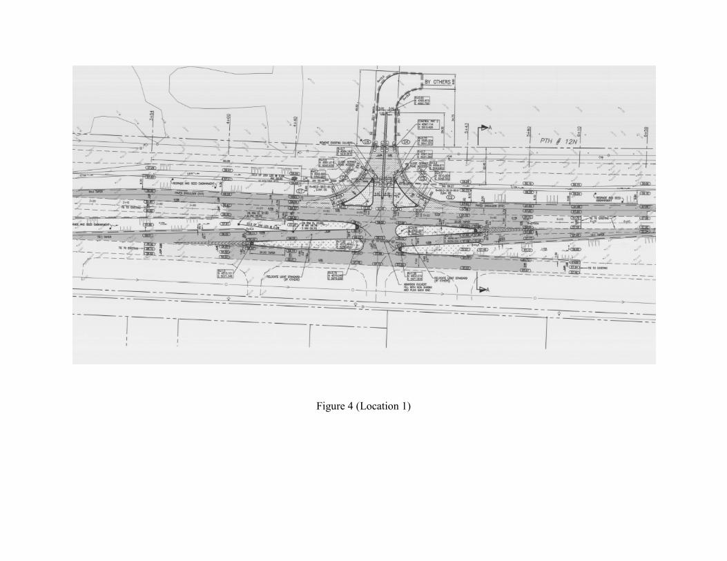
Figure 4 (Location 1)
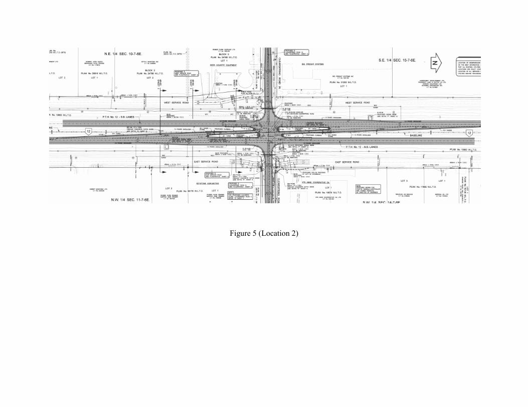
Figure 5 (Location 2)

Figure 6 (Location 1)
Figure 7 (Location 3)
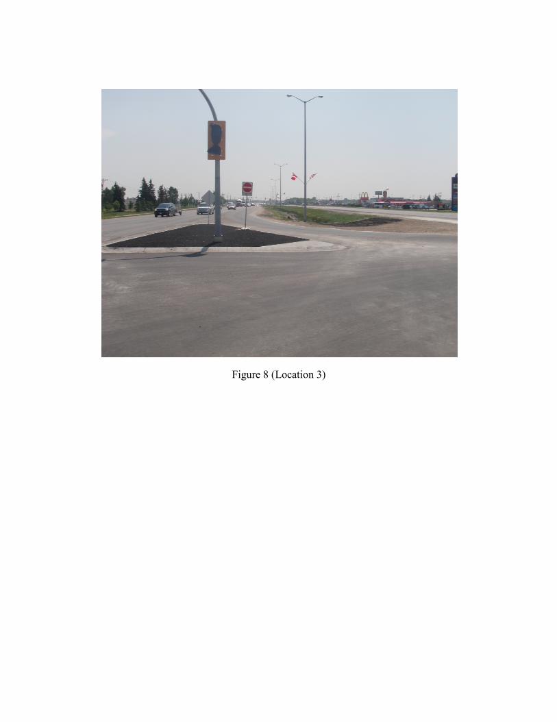
Figure 8 (Location 3)