
Design and implementation of Open & Close Loop Speed...
12
International Journal of Engineering Research and General Science Volume 6, Issue 2, March-April, 2018 ISSN 2091-2730 6 www.ijergs.org Design and implementation of Open & Close Loop Speed control of Three Phase Induction Motor Using PI Controller Ibtisam Naveed 1 , Adnan Sabir 2 1 (Electrical Engineering, NFC institute of Engineering and Fertilizer Research Faisalabad, Pakistan) 2 (Software Engineering, COMSATS institute of information Technology, Sahiwal Pakistan) ABSTRACT- The induction motors were characterized by complex, highly non-linear and time-varying dynamics, and hence their speed control is a challenging problem in the industry. The aim of this paper is to present the speed control of three phase induction motors by variable frequency drive. The variable frequency drive for induction motors is achieved using SPWM which provide better efficiency and higher performance. The motor speed is investigated both at fixed load and variable load. Moreover a close loop PI controller was designed at rated load based on dynamic behavior of error signal. It has been found that by designing a proper PI controller the motor starting current is reduced significantly. Moreover at rated torque efficiently speed of motor can be controlled. PI speed controller not help to reduce dynamic performance of the system but also help to reduce the steady state error, the error sensibility, high performance and smooth speed response. The complete mathematical model of the system is described and simulated in MATLAB/SIMULINK. The simulation results provide a smooth speed response and high performance under various dynamic operations.Keywords— Induction Motor, PI controller, SPWM technique, Voltage Source Inverter (VSI) 1. Introduction Induction motor is the most widely used in industry because of its high robustness, reliability, low cost, high efficiency and good self starting capability. Moreover during the last few years, feasible controls of induction motor has received a lot of attention with the development of Power electronic devices like IGBT, MOSFET etc. and make an active research area for engineers. The speed control of induction motor is more important to achieve maximum torque and efficiency [1-2]. Various methods based on speed and torqueses with different technique are deployed for speed control of induction motors. These methods mostly are scalar control, vector or field-oriented control, direct and flux control, sliding mode control, Fuzzy logic Control (FLC) and the adaptive control [3- 6].Direct Torque Control (DTC) based method gives faster and robust responses of various parameters in the induction motors but the output responses of torque and flux are noisy [7]. FLC based proportional controller (PI) has high accuracy and less circuit complexity. However FLC controllers are less sensitive to system parameters variations and therefore difficult to achieve robustness [8]. The benefit of SPWM technique is that not only provide better efficiency but also help to increase the performance of induction motor when compared with fixed frequency motor drive. The advantage of using SPWM help to shrink the harmonic content of output voltage compared to single pulse width modulation and multi-pulse modulation. In this paper, a three phase inverter, controlled by SPWM technique driving a three phase induction motor at fixed and variable load is presented. The harmonic analysis also performed using FFT tool to observe the harmonics content in Voltage Source Inverter. Moreover the close loop system PI controller is designed which help to maintain the speed of the motor at rated torque. 2. Modeling of Induction Motor The dynamic model is used to obtain the transient and steady state behavior of induction motor. Analysis of the dynamic behavior of Induction Motor are described the equation of induction motor. The stator and rotor voltage equation of motor is described as: qs ds s qs s qs ds qs s ds s ds p i R v p i R v (1) Where ds s i R is stator winding voltage drop, qs s is speed voltage term and qs p is transient term. qr dr s qr r qr dr qr s dr r dr p s i R v p s i R v (2)
Transcript of Design and implementation of Open & Close Loop Speed...

International Journal of Engineering Research and General Science Volume 6, Issue 2, March-April, 2018 ISSN 2091-2730
6 www.ijergs.org
Design and implementation of Open & Close Loop Speed control of Three
Phase Induction Motor Using PI Controller
Ibtisam Naveed1, Adnan Sabir2
1(Electrical Engineering, NFC institute of Engineering and Fertilizer Research Faisalabad, Pakistan)
2(Software Engineering, COMSATS institute of information Technology, Sahiwal Pakistan)
ABSTRACT- The induction motors were characterized by complex, highly non-linear and time-varying dynamics, and hence their
speed control is a challenging problem in the industry. The aim of this paper is to present the speed control of three phase induction
motors by variable frequency drive. The variable frequency drive for induction motors is achieved using SPWM which provide better
efficiency and higher performance. The motor speed is investigated both at fixed load and variable load. Moreover a close loop PI
controller was designed at rated load based on dynamic behavior of error signal. It has been found that by designing a proper PI
controller the motor starting current is reduced significantly. Moreover at rated torque efficiently speed of motor can be controlled. PI
speed controller not help to reduce dynamic performance of the system but also help to reduce the steady state error, the error
sensibility, high performance and smooth speed response. The complete mathematical model of the system is described and simulated
in MATLAB/SIMULINK. The simulation results provide a smooth speed response and high performance under various dynamic
operations.Keywords— Induction Motor, PI controller, SPWM technique, Voltage Source Inverter (VSI)
1. Introduction
Induction motor is the most widely used in industry because of its high robustness, reliability, low cost, high efficiency and good self
starting capability. Moreover during the last few years, feasible controls of induction motor has received a lot of attention with the
development of Power electronic devices like IGBT, MOSFET etc. and make an active research area for engineers. The speed control
of induction motor is more important to achieve maximum torque and efficiency [1-2]. Various methods based on speed and
torqueses with different technique are deployed for speed control of induction motors. These methods mostly are scalar control,
vector or field-oriented control, direct and flux control, sliding mode control, Fuzzy logic Control (FLC) and the adaptive control [3-
6].Direct Torque Control (DTC) based method gives faster and robust responses of various parameters in the induction motors but
the output responses of torque and flux are noisy [7]. FLC based proportional controller (PI) has high accuracy and less circuit
complexity. However FLC controllers are less sensitive to system parameters variations and therefore difficult to achieve robustness
[8]. The benefit of SPWM technique is that not only provide better efficiency but also help to increase the performance of induction
motor when compared with fixed frequency motor drive. The advantage of using SPWM help to shrink the harmonic content of
output voltage compared to single pulse width modulation and multi-pulse modulation. In this paper, a three phase inverter,
controlled by SPWM technique driving a three phase induction motor at fixed and variable load is presented. The harmonic analysis
also performed using FFT tool to observe the harmonics content in Voltage Source Inverter. Moreover the close loop system PI
controller is designed which help to maintain the speed of the motor at rated torque.
2. Modeling of Induction Motor
The dynamic model is used to obtain the transient and steady state behavior of induction motor. Analysis of the dynamic behavior
of Induction Motor are described the equation of induction motor. The stator and rotor voltage equation of motor is described as:
qsdssqssqs
dsqssdssds
piRv
piRv
(1)
Where dssiR is stator winding voltage drop, qss is speed voltage term and qsp is transient term.
qrdrsqrrqr
drqrsdrrdr
psiRv
psiRv
(2)

International Journal of Engineering Research and General Science Volume 6, Issue 2, March-April, 2018 ISSN 2091-2730
7 www.ijergs.org
Where drss is rotor speed voltage created in the Rotor windings moving at slip speed w.r.t to the synchronously rotating flux
wave. Power input to stator and rotor equations described as:
qsqsdsdss ivivP (3)
qrqrdrdrr ivivP (4)
The torque and Speed equation is described as:
Ler
qrdrdrqre
TTJ
P
IIP
T
*2
22
3
(5)
Where, P denote the no. of poles ; J: moment of inertia ,after driving the torque and speed equation in terms of dq flux linkage and
current of the stator, the dq axis transformation should now be applied to the machine input(stator) voltage [9].
2.1 Block diagram of open loop system
The block diagram of system consists of three main parts. The DC voltage source, Voltage Source inverter and three phase induction
motor. The output of Voltage source inverter can be found using this equation.
dcrms VmV **612.0 (6)
Where m is a modulation index of VSI and dcV is the DC voltage.
The speed and driving Torque of motor can be found as
P
fNs
*120 (7)
Where Ns is synchronous speed in rpm, f is frequency in Hz and P is the No. of poles.
w
PT m
n (8)
Where mP is motor power in watt and w is rad/sec and nT is in Nm.

International Journal of Engineering Research and General Science Volume 6, Issue 2, March-April, 2018 ISSN 2091-2730
8 www.ijergs.org
Fig. 2.1 The block diagram of open loop speed control of three phase induction motor
2.1.1 MATLAB/ Simulink Model implementation at rated load
Fig. 2.2 An open loop Matlab/Simulink model for speed control of three phase induction motor at fixed/rated load
The nominal voltage 220 Vrms (L-L) for the input of three phases IM is calculated by Eq. (6) which is a function of dc voltage and
modulation index factor (m). The synchronous speed of induction motor is calculated using Eq. (7) which is 1800 rpm (188.496
rad/sec). The nominal torque for IM is calculated using Eq. (8) which is 11.87 (Nm). For the sake of simplicity and check the effect of
speed of IM at rated and variable load the PWM is generated by build in block by keeping carrier frequency at 1080 Hz. The block has
been discretized so that the pulses change at multiples of the specified time step. A time step of 10 µs corresponds to +/- 0.54% of the
switching period at 1080 Hz.
2.1.1.1 Simulation Result of open loop speed control of IM at rated load
At starting the motor speed increase to 181.8 rad/sec (1736 rpm) and then decrease and reaches its steady-state value of 175.5 rad/s
(1675 rpm) after 0.1 s at rated load 11.87 Nm. At starting, the magnitude of the 60 Hz current increase gradually and reaches to steady
state value of 12 A peak (8.48 A RMS). As expected, the magnitude of the 60 Hz voltage contained in the chopped wave stays at 311
V.
Also notice that at starting the electromagnetic torque reaches at highest value of 32 Nm and come to steady state at a value of 11.87
Nm corresponding to the load torque at nominal speed. Moreover it is noticed that all the harmonics (multiples of the 1080 Hz
switching frequency) are filtered by the stator inductance, so that the 60 Hz component is dominant.

International Journal of Engineering Research and General Science Volume 6, Issue 2, March-April, 2018 ISSN 2091-2730
9 www.ijergs.org
Fig. 2.3 RMS Line voltage at the output of VSI
Fig. 2.3 An open loop Matlab/Simulink model for speed control of three phase induction motor at fixed/rated load
Fig. 2.4 Nominal speed of IM at rated load
Fig. 2.5 Nominal Electromagnetic torque of IM at rated speed

International Journal of Engineering Research and General Science Volume 6, Issue 2, March-April, 2018 ISSN 2091-2730
10 www.ijergs.org
Fig. 2.6 Stator current of IM at rated load
The internal measurement of VSI block is done by millimeter. The simulation result is carried for 20 msec. A positive current indicate
that a current is flowing in the MOSFET/IGBT while a negative current indicate that the current flowing in the antiparallel diode.
Fig. 2.7 Internal current flowing in the IGBT
2.1.1.2 MATLAB/ Simulink Model implementation at variable load

International Journal of Engineering Research and General Science Volume 6, Issue 2, March-April, 2018 ISSN 2091-2730
11 www.ijergs.org
Fig. 2.8 An open loop Matlab/Simulink model for speed control of three phase induction motor at variable load
By keeping above all parameter same, the variable load at the input of motor is applied as follows;
Tm = 0 Nm 0 < t < 0.5
Tm = 11.87 NM t > 0.5
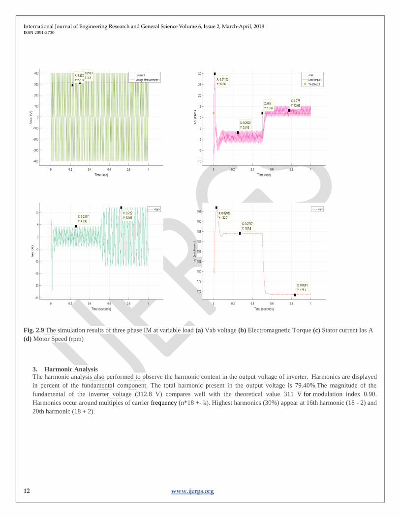
2.1.1.3 Simulation Result of open loop speed control of IM at variable load
The simulation results of three phase IM at variable load is shown indicate that At starting the motor speed increase to 192.7 rad/sec
(1840 rpm) because of inertia and inrush current and eventually decrease and reach a value of 187.6 rpm (1791 rpm) which is slight
close to synchronous speed for interval of 0 < t < 0.5. As load on motor increase then speed of motor decrease and reach its steady-
state value of 175.5 rad/s (1675 rpm) after 0.5 s corresponding load 11.87 Nm. At interval 0 < t < 0.5 the magnitude of the 60 Hz
current observed 4.836 peak (3.4195 A RMS) and increase gradually with increasing load and reaches to steady state value of 12 A
peak (8.48 A RMS) for interval t > 0.5. As expected, the magnitude of the 60 Hz voltage contained in the chopped wave stays at 311
V.
Moreover it is noticed that all the harmonics (multiples of the 1080 Hz switching frequency) are filtered by the stator inductance, so
that the 60 Hz component is dominant.
International Journal of Engineering Research and General Science Volume 6, Issue 2, March-April, 2018 ISSN 2091-2730
12 www.ijergs.org
Fig. 2.9 The simulation results of three phase IM at variable load (a) Vab voltage (b) Electromagnetic Torque (c) Stator current Ias A
(d) Motor Speed (rpm)
3. Harmonic Analysis
The harmonic analysis also performed to observe the harmonic content in the output voltage of inverter. Harmonics are displayed
in percent of the fundamental component. The total harmonic present in the output voltage is 79.40%.The magnitude of the
fundamental of the inverter voltage (312.8 V) compares well with the theoretical value 311 V for modulation index 0.90.
Harmonics occur around multiples of carrier frequency (n*18 +- k). Highest harmonics (30%) appear at 16th harmonic (18 - 2) and
20th harmonic (18 + 2).

International Journal of Engineering Research and General Science Volume 6, Issue 2, March-April, 2018 ISSN 2091-2730
13 www.ijergs.org
Fig.3.1 The harmonic analysis of motor line-line voltage
4. Block diagram of close loop system
The block diagrams of close loop system consist of PI controller, VSI and three phase induction motor. The measured speed is
compared with reference speed and desired signal is generated which is fed to the input of voltage source inverter.
Fig 4.1 The block diagram of close loop system
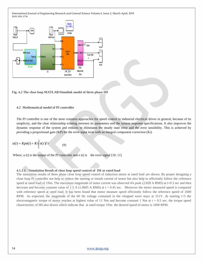
4.1 MATLAB/ Simulink Model implementation of close loop
International Journal of Engineering Research and General Science Volume 6, Issue 2, March-April, 2018 ISSN 2091-2730
14 www.ijergs.org
Fig. 4.2 The close loop MATLAB/Simulink model of three phase IM
4.2 Mathematical model of PI controller
The PI controller is one of the most common approaches for speed control in industrial electrical drives in general, because of its
simplicity, and the clear relationship existing between its parameters and the system response specifications. It also improves the
dynamic response of the system and reduces or eliminates the steady state error and the error sensibility. This is achieved by
providing a proportional gain (KP) for the error input term with an integral component correction (Ki)
t
eKitKpetu0
)()()( (9)
Where, u (t) is the output of the PI controller and e (t) is the error signal [10, 11]
4.1.1.1 Simulation Result of close loop speed control of IM at rated load
The simulation results of three phase close loop speed control of induction motor at rated load are shown. By proper designing a
close loop PI controller not help to reduce the starting or inrush current of motor but also help to efficiently follow the reference
speed at rated load of 1Nm. The maximum magnitude of stator current was observed 4A peak (2.828 A RMS) at t=0.3 sec and then
decrease and become constant value of 1.5 A (1.0605 A RMS) at t = 0.45 sec. Moreover the motor measured speed is compared
with reference speed at rated load. It has been found that motor measure speed efficiently follow the reference speed of 1600
RPM. As expected, the magnitude of the 60 Hz voltage contained in the chopped wave stays at 311V. At starting t<5 the
electromagnetic torque of motor reaches at highest value of 11 Nm and become constant 1 Nm at t = 0.5 sec. the torque speed
characteristic of IM also drawn which indicate that at rated torque 1Nm the desired speed of motor is 1600 RPM.

International Journal of Engineering Research and General Science Volume 6, Issue 2, March-April, 2018 ISSN 2091-2730
15 www.ijergs.org
Fig. 4.3 RMS Line voltage at the output of VSI
Fig. 4.4 Stator current of IM at rated load
Fig 4.5 Nominal Electromagnetic torque of IM at rated speed

International Journal of Engineering Research and General Science Volume 6, Issue 2, March-April, 2018 ISSN 2091-2730
16 www.ijergs.org
Fig 4.6 Nominal speed of IM at rated load
Fig. 4.7 Torque Speed characteristic of IM at rated load of 1Nm
5. Conclusion
The speed control of three phase induction motor has been invested both for open and close loop. It can be concluded that by proper
designing a PI speed controller not help to reduce dynamic performance of the system but also help to reduce the steady state error, the
error sensibility, high performance and smooth speed response. Both open and close loop method have its own advantage and
disadvantage. open loop deals with constant speed applications, many applications in the industry operate with this control technique.
However The inrush current is very large for open loop system which cause a lot of voltage drop and voltage sag in a system and also
may cause the shorten life of motor. Compared this starting current is very less in case of close loop PI system. The PI control
technique control is a low cost method, simple and immunity to errors of feedback signals.
International Journal of Engineering Research and General Science Volume 6, Issue 2, March-April, 2018 ISSN 2091-2730
17 www.ijergs.org
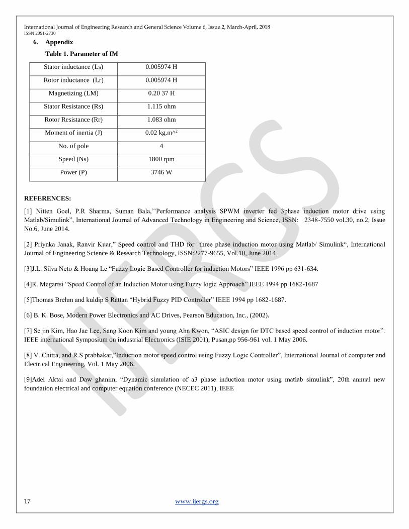
6. Appendix
Table 1. Parameter of IM
Stator inductance (Ls) 0.005974 H
Rotor inductance (Lr) 0.005974 H
Magnetizing (LM) 0.20 37 H
Stator Resistance (Rs) 1.115 ohm
Rotor Resistance (Rr) 1.083 ohm
Moment of inertia (J) 0.02 kg.m^2
No. of pole 4
Speed (Ns) 1800 rpm
Power (P) 3746 W
REFERENCES:
[1] Nitten Goel, P.R Sharma, Suman Bala,’’Performance analysis SPWM inverter fed 3phase induction motor drive using
Matlab/Simulink”, International Journal of Advanced Technology in Engineering and Science, ISSN: 2348-7550 vol.30, no.2, Issue
No.6, June 2014.
[2] Priynka Janak, Ranvir Kuar,” Speed control and THD for three phase induction motor using Matlab/ Simulink“, International
Journal of Engineering Science & Research Technology, ISSN:2277-9655, Vol.10, June 2014
[3]J.L. Silva Neto & Hoang Le “Fuzzy Logic Based Controller for induction Motors” IEEE 1996 pp 631-634.
[4]R. Megartsi “Speed Control of an Induction Motor using Fuzzy logic Approach” IEEE 1994 pp 1682-1687
[5]Thomas Brehm and kuldip S Rattan “Hybrid Fuzzy PID Controller” IEEE 1994 pp 1682-1687.
[6] B. K. Bose, Modern Power Electronics and AC Drives, Pearson Education, Inc., (2002).
[7] Se jin Kim, Hao Jae Lee, Sang Koon Kim and young Ahn Kwon, “ASIC design for DTC based speed control of induction motor”.
IEEE international Symposium on industrial Electronics (ISIE 2001), Pusan,pp 956-961 vol. 1 May 2006.
[8] V. Chitra, and R.S prabhakar,”Induction motor speed control using Fuzzy Logic Controller”, International Journal of computer and
Electrical Engineering, Vol. 1 May 2006.
[9]Adel Aktai and Daw ghanim, “Dynamic simulation of a3 phase induction motor using matlab simulink”, 20th annual new
foundation electrical and computer equation conference (NECEC 2011), IEEE