Implementation of 16-Bit Hamming Code encoder and decoder ...

International Journal of Latest Engineering Research and Applications (IJLERA) ISSN: 2455-7137
Volume – 02, Issue – 11, November – 2017, PP – 33-40
www.ijlera.com 2017 IJLERA – All Right Reserved 33 | Page
Design and Implementation of Hamming Code using VHDL &
DSCH
Divya Mokara1, Sushmi Naidu
2, Akash Kumar Gupta
3 1(Department of ECE, Raghu Institute of Technology, Visakhapatnam, India)
2(Department of ECE, Raghu Institute of Technology, Visakhapatnam, India)
3(Department of ECE, Raghu Institute of Technology, Visakhapatnam, India)
Abstract: Error free transmission is a major concern in advanced electronic circuits. The errors in
information occur during transmission which can lead to wrong information at reception. Error correction codes
are commonly used to protect the information in memories and registers in electronic circuits. Hamming code is
one of such forward error correcting code. It uses either even parity or odd parity check method. Here we
implemented hamming code using even parity check method. Hamming code is an improvement over parity
check method. Here the hamming code is implemented in Xilinx in which 7-bits of information data is
transmitted with 4 redundant bits and it is also implemented in DSCH (Digital Schematic Editor & Simulator)
tool. A special parity bit is used to detect the double bit error. Here we used SEDC-DED (Single Bit Error
Detection and Correction-Double Bit Error Detection) algorithm for error detection and error correction.
Keywords: DSCH, Even parity, FPGA-Xilinx, Hamming code, VHDL.
1. Introduction In digital communication, errors are introduced during the transmission of data from the transmitter to
receiver due to noise or environmental interference. Error is a condition when the output information does not
match with the input information that means „0‟ bit may change to „1‟ or a „1‟ bit may change to „0‟. These
errors can become a serious problem for achieving accuracy and performance of the system. Therefore, the
reliability of data transmission is required to be improved. To improve the reliability, it is essential to detect and
correct the error. Hence, we have to use some kind of error detection and error correction codes. In this type of
codes, one or more than one extra bit is added to the data bits at the time of transmitting the data. These extra
bits are called parity bit that helps to detect the errors. A parity bit or a check bit is a bit added to the end of a
string of binary code that indicates whether the number of bits in the string is even or odd. The parity may be
either even or odd. Even parity means, the number of 1's in the given word including the parity bit should be
even (2, 4, 6....). Odd parity means, the number of 1's in the given word including the parity bit should be odd
(1, 3, 5.....).
The data bits along with the parity bit forms a code word. Codes which allow only error detection are
called error detection codes and are used to detect an error occurred during transmission of the message. A
simple example of error-detecting code is parity check and codes which allow error detection and error
correction are called error detecting and correcting codes. In error-correcting codes, parity check has a simple
way to detect errors along with a sophisticated mechanism to determine the corrupted bit location. Once the
corrupted bit is located, its value is reverted (from 0 to 1 or 1 to 0) to get the original message.
There are different types of error controlling codes such as parity checking, check sum error detection,
cyclic redundancy check, VRC, LRC & Hamming code. Comparing with other error controlling codes,
hamming code has high efficiency for error detection as well as for error correction and this code is also easy to
implement.
2. Hamming Code Hamming code not only provides the detection of a bit error but also identifies which bit is in error so
that it can be corrected. Thus, the hamming code is called error detecting and error correcting code. It is used to
detect & correct a single bit error and also used to detect a double bit error. Because of its simplicity, hamming
code is widely used in computing memory, data compression & other application of telecommunication.
The code uses a number of parity bits (dependent on the number of information bits) located at certain
positions in the code group. If the number of bits designated as „X‟ then the number of parity bits, „P‟ is
determined by the following relationship
: 2P ≥ X + P + 1 (1)

International Journal of Latest Engineering Research and Applications (IJLERA) ISSN: 2455-7137
Volume – 02, Issue – 11, November – 2017, PP – 33-40
www.ijlera.com 2017 IJLERA – All Right Reserved 34 | Page
For seven information bits, X=7, then the number of parity bits „P‟ is obtained by trial and error using
the above equation (1). Thus 4 parity bits are required for 7 information bits and these 4 parity bits are placed in
the powers of 2.
2.1 Hamming Code Algorithm
The general algorithm for the hamming code is as follows: 1. „P‟ parity bits are added to X-bit data word, forming a code word of X+P bits.
2. The bit positions are numbered in sequence from 1 to X+P.
3. These positions are numbered in powers of 2, reserved for the parity bits and the remaining bits are
data bits.
4. Parity bits are calculated by XOR operation of some combination of data bits.
The method of parity bits are calculated is as follows:
P1 = XOR of bit positions (1, 3, 5, 7, 9, 11, 13...)
P2 = XOR of bit positions (2, 3, 6, 7, 10, 11...)
P4 = XOR of bit positions (4, 5, 6, 7, 13....)
P8 = XOR of bit position (8, 9, 10, 11, 12, 13...)
2.2 SEDC-DED Algorithm The basic hamming code can detect and correct single bit error only. By adding another parity bit P9 to
the coded word the Hamming code can also be used to detect double bit errors. If we include this additional
parity bit to the 11-bit coded word then it becomes a 12-bit coded word. This method is called SEDC-DED
algorithm and is shown in below Fig. 1. Here P9 (additional parity bit) is evaluated by XOR of all the 11-bits.
Fig. 1: Flowchart for SEDC-DED Algorithm
3. Information Transfer Consider a 7-bit data word 1010110 as shown in Table 1.
Bit Position 7 6 5 4 3 2 1
Code Word D7 D6 D5 D4 D3 D2 D1
Data Bits 0 1 1 0 1 0 1
Table 1: Original Data Bits

International Journal of Latest Engineering Research and Applications (IJLERA) ISSN: 2455-7137
Volume – 02, Issue – 11, November – 2017, PP – 33-40
www.ijlera.com 2017 IJLERA – All Right Reserved 35 | Page
Here we include 4 redundant parity bits with this 7-bit data word, which produces 11-bits as an
encrypted codeword. This code word is transmitted at the receiver end, which is examined by checker bits to
detect and correct if any error occurred during transmission
3.1 Data Encryption with Hamming Code
3.1.1 Encoder Circuit
The data word is applied as an input to the encoder circuit which performs XOR operations on the
given data word and thus the required parity bits are generated from the parity bit generator. Parity bits and data
bits together form the code word. An encoder circuit of hamming code for 4-bit data word is shown Fig. 2.
Following this circuit pattern, we can design an encoder circuit of hamming code for 7-bit data word and it is
implemented in DSCH tool.
Fig. 2: Hamming Encoder Circuit
The above Fig. 2 consists of 4-bit data word, parity bit generator and 7-bit code word. The 4-bit data
word is applied as an input to the encoder circuit, now the encoder output consist of 7-bits i.e. 4-data bits D1,
D2, D3 & D4 and 3-parity bits P1, P2 & P4. Similarly, for a 7-bit data word, the code word consists of 11-bits
i.e. 7-data bits D1, D2, D3, D4, D5, D6, D7 and 4- parity bits P1, P2, P4 & P8 as shown in Table 2.
The parity bits calculated for 7-bit data is as follows:
P1=D1⨁D2⨁D4⨁D5⨁D7
P2=D1⨁D3⨁D4⨁D6⨁D7
P4=D2⨁D3⨁D4
P8=D5⨁D6⨁D7
Bit Position 11 10 9 8 7 6 5 4 3 2 1
Code Word D7 D6 D5 P8 D4 D3 D2 P4 D1 P2 P1
Encoded
Data Bits
0 1 1 0 0 1 0 1 1 1 0
Table 2: 11-Bits of Encoded Data
3.2 Data Decryption with Hamming Code using SEDC-DED Algorithm
3.2.1 Decoder Circuit
A decoder circuit of hamming code for 4-bit data word is shown in Fig. 3. The circuit consists of
checker bit generator, 3 to 8 decoder and XOR gates. In this circuit, the code word is applied as an input then the
check bits are generated by the checker bit generator, these bits are given to the decoder that enables the XOR
gate which is having the error. Depending on the correction algorithm either it will be detected or corrected.

International Journal of Latest Engineering Research and Applications (IJLERA) ISSN: 2455-7137
Volume – 02, Issue – 11, November – 2017, PP – 33-40
www.ijlera.com 2017 IJLERA – All Right Reserved 36 | Page
Fig. 3: Hamming Decoder circuit
The decoder circuit of 7-bit data word consists of checker bit generator, 4 to 16 decoder and XOR
gates. The error detection and correction is done as similar to 4-bit hamming decoder. The checker bits for 11-
bit code word & the 12th bit i.e. overall parity bit P9 is calculated as follows:
C1=D1⨁ D3 ⨁D5⨁D7⨁D9⨁D11
C2=D2⨁ D3⨁ D6⨁D7⨁D10⨁D11
C3=D4⨁D5⨁ D6⨁D7
C4=D8⨁D9⨁ D10⨁D11
P9= D1⨁ D2⨁ D3⨁ D4⨁D5⨁D6⨁D7⨁ D8⨁D9⨁D10⨁D11.
The detection and correction algorithm works on the following „3‟ conditions.
1. If C=0 and P9=0
There is no error in the transmitted codeword, so the codeword is taken as valid information.
2. If C ≠ 0 and P9= 1
A single bit error occurred that can be detected and corrected.
3. If C ≠ 0 and P9= 0
Double bit error occurred that cannot be corrected, so the codeword is taken as invalid information.
Here „C‟ indicates the 4 parity bits (P8P4P2P1).
The above generated checker bits are given to the decoder which locates the error in the given code
word. If no error occurs then received data is considered as valid information and if an error occurs then the
output of the decoder enables the XOR gate which is having an error and is corrected by inverting the bit and the
data is validated.
The decoder will receive the data for „3‟ different conditions are shown in below tables.
Bit Position 12 11 10 9 8 7 6 5 4 3 2 1
Code Word P9 D7 D6 D5 P8 D4 D3 D2 P4 D1 P2 P1
Received Data Bits 0 0 1 1 0 0 1 0 1 1 1 0
Table 3: Received Data Bits with No Error
Bit Position 12 11 10 9 8 7 6 5 4 3 2 1
Code Word P9 D7 D6 D5 P8 D4 D3 D2 P4 D1 P2 P1
Received Data Bits 1 1 1 0 1 1 0 0 1 0 0 1
Table 4: Received Data Bits with Single Error
Bit Position 12 11 10 9 8 7 6 5 4 3 2 1
Code Word P9 D7 D6 D5 P8 D4 D3 D2 P4 D1 P2 P1
Received Data Bits 0 0 1 1 1 0 1 1 0 1 1 1
Table 5: Received Data Bits with Double Error

International Journal of Latest Engineering Research and Applications (IJLERA) ISSN: 2455-7137
Volume – 02, Issue – 11, November – 2017, PP – 33-40
www.ijlera.com 2017 IJLERA – All Right Reserved 37 | Page
4. Design Simulation and Validation All the designs of hamming encoder and decoder are simulated in Xilinx ISE and DSCH tool. The
simulation results are shown below Figures.
4.1 Simulation Output of Hamming Encoder Implemented in Xilinx ISE
Fig. 4: Simulation Waveform of Encoder
4.2 Simulation Output for No Error Implemented in Xilinx ISE
Fig. 5: Simulation Waveform for No Error
4.3 Simulation Output for Single Error Implemented in Xilinx ISE
Fig. 6: Simulation Waveform for Single Error
International Journal of Latest Engineering Research and Applications (IJLERA) ISSN: 2455-7137
Volume – 02, Issue – 11, November – 2017, PP – 33-40
www.ijlera.com 2017 IJLERA – All Right Reserved 38 | Page
4.4 Simulation Output for Double Error Implemented in Xilinx ISE
Fig. 7: Simulation Waveform for Double Error
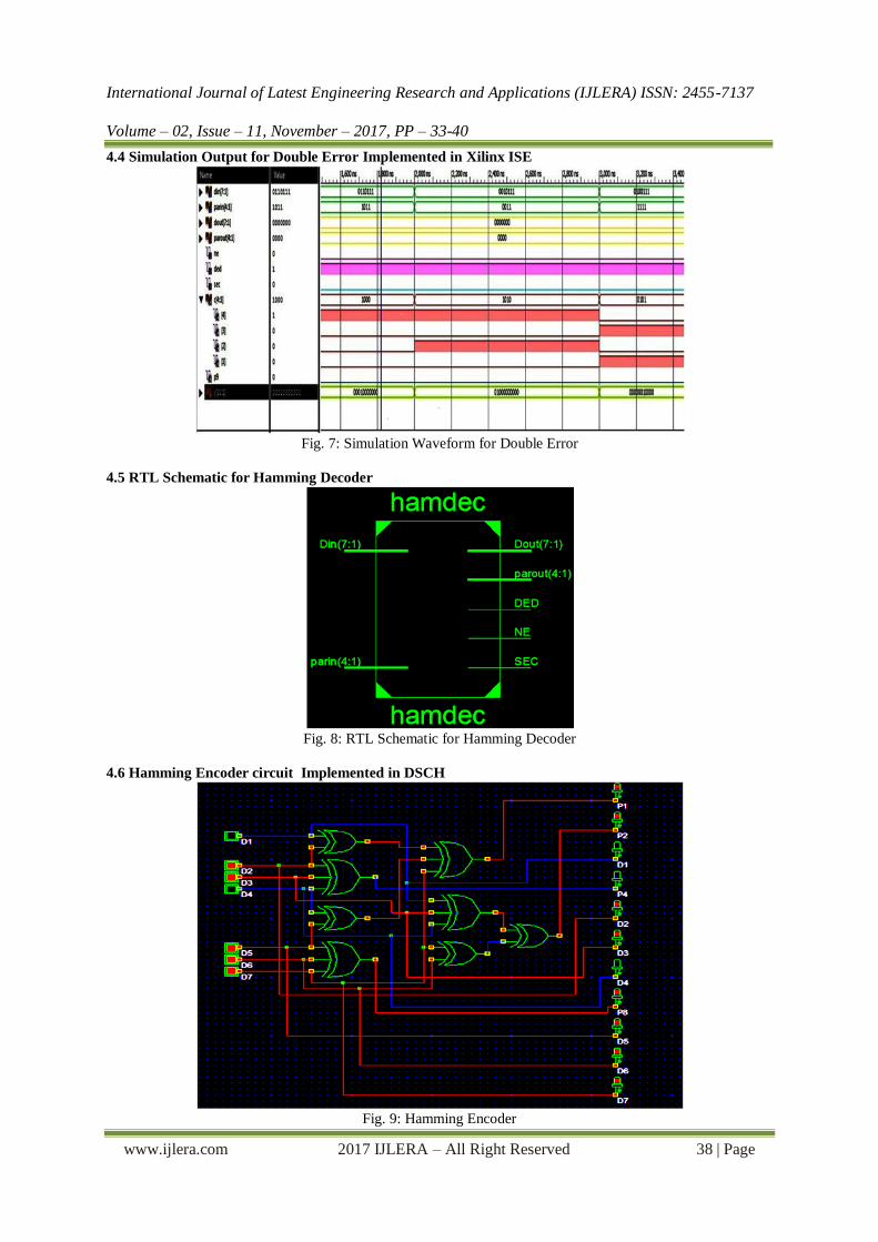
4.5 RTL Schematic for Hamming Decoder
Fig. 8: RTL Schematic for Hamming Decoder
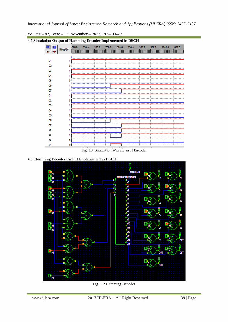
4.6 Hamming Encoder circuit Implemented in DSCH
Fig. 9: Hamming Encoder
International Journal of Latest Engineering Research and Applications (IJLERA) ISSN: 2455-7137
Volume – 02, Issue – 11, November – 2017, PP – 33-40
www.ijlera.com 2017 IJLERA – All Right Reserved 39 | Page
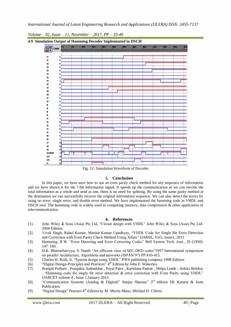
4.7 Simulation Output of Hamming Encoder Implemented in DSCH
Fig. 10: Simulation Waveform of Encoder
4.8 Hamming Decoder Circuit Implemented in DSCH
Fig. 11: Hamming Decoder
International Journal of Latest Engineering Research and Applications (IJLERA) ISSN: 2455-7137
Volume – 02, Issue – 11, November – 2017, PP – 33-40
www.ijlera.com 2017 IJLERA – All Right Reserved 40 | Page
4.9 Simulation Output of Hamming Decoder Implemented in DSCH
Fig. 12: Simulation Waveform of Decoder
5. Conclusion
In this paper, we have seen how to use an even parity check method for any sequence of information
and we have shown it for the 7-bit information signal. It speeds up the communication as we can encode the
total information as a whole and send as one, there is no need for splitting. By using the same parity method at
the destination we can successfully recover the original information sequence. We can also detect the errors by
using no error, single error, and double error method. We have implemented the hamming code in VHDL and
DSCH tool. The hamming code is widely used in computing memory, data compression & other application of
telecommunication.
6. References [1]. John Wiley & Sons (Asia) Pte Ltd, “Circuit design with VHDL” John Wiley & Sons (Asia) Pte Ltd-
2004 Edition.
[2]. Vivek Singh, Rahul Kumar, Manish Kumar Upadhyay, “VHDL Code for Single Bit Error Detection
and Correction with Even Parity Check Method Using Xilinx” IJARSE, Vol1, Issue1, 2013
[3]. Hamming, R.W. “Error Detecting and Error Correcting Codes” Bell System Tech. Jour., 29 (1950):
147–160.
[4]. D.K. Bhattacharryya, S. Nandi “An efficient class of SEC-DED codes”1997 International symposium
on parallel Architecture, Algorithms and networks (ISPAN‟97) PP.410-415.
[5]. Charles H. Roth, Jr. “System design using VHDL” PWS publishing company-1998 Edition.
[6]. “Digital Design-Principles and Practices” 4th Edition by John F. Wakerley.
[7]. Pranjali Pothare , Pranjakta Ambatkhar , Payal Patre , Karishma Padole , Shilpa Lende , Ankita Belekar
, “Hamming code for single bit error detection & error correction with Even Parity using VHDL”
IJARCET volume 4 , Issue 1,January 2015.
[8]. “Communication Systems (Analog & Digital)” Sanjay Sharma” 3rd
edition SK Kataria & Sons
Publication.
[9]. “Digital Design” Pearson 4th Edition by M. Morris Mano, Michael D. Cliletti.