Design and Implementation of Floating Point … and Implementation of Floating Point Multiplier ......
15
International Journal of Applied Sciences and Management ISSN 2413-3396 Vol. 1, no. 1, 48-62, 2015 48 Int. j. appl. sci. manag. Design and Implementation of Floating Point Multiplier using VHDL 1 Sumod Abraham, 2 Sukhmeet Kaur 1 Student, Manav Rachna College of Engineering, India, [email protected] 2 Asst. Professor, Manav Rachna College of Engineering, India, [email protected] Abstract Various arithmetic operations determine the speed of the processors. Out of the other arithmetic operations, multiplication is the most time consuming. So, the aim of this paper is to design and implement a multiplier which is less time consuming and also occupies less area. This multiplier will multiply two floating point numbers (in single precision format). Here, floating point arithmetic algorithm is used but in mantissa multiplication step, rather than conventional multiplication, Booth Dadda multiplier is used. This multiplier is combination of advanced Booth multiplier and Dadda multiplier. Simulation is done using VHDL in Xilinx ISE Design suite 13.2 and is found that Booth Dadda multiplier is faster and at the same time occupies less area than other conventional multipliers. Keywords: Multiplier, Dadda, mantissa, Booth Dadda, VHDL. 1. Introduction With time, technology too has developed but in a high pace which resulted in the fact that everyone demands for high speed devices that can help them do multitasking. For increasing the speed of a device, processor that is in it must also work in high speed. When it comes to high speed processors, high speed multipliers play a vital role, as when compared with other arithmetic operations, it is multiplication which is the most complex operation that is used frequently. Multipliers are important components of various real time processing devices or systems that are based on arithmetic operations. Multiplication is a process in which partial products that are generated are added together to yield a final product. In multiplication, the number which is to be multiplied, (number that is on top) is called mantissa and the number of times that this number is to be multiplied (number in the bottom) is called multiplier. Multiplication is the repetitive addition of the partial products [1]. Almost in all digital signal processors and image processing devices, multipliers play a significant role. There are a lot of algorithms related to multiplication which are used today for processing. Normally the number of partial products that are generated depends on the size of the multiplier. That is, if the multiplier is say, of 5 bits then there will be five partial products. In other words, more the size of the multiplier, more will be the number of partial products formed and more will be its complexity to solve it. Numbers are the base of arithmetic operations. These numbers are clubbed together and called number system. There are various sets in number system based on which it is classified such as integers, natural numbers etc. out of this set, this paper focuses on floating point numbers.
Transcript of Design and Implementation of Floating Point … and Implementation of Floating Point Multiplier ......

International Journal of Applied Sciences and Management ISSN 2413-3396 Vol. 1, no. 1, 48-62, 2015
48 Int. j. appl. sci. manag.
Design and Implementation of Floating Point Multiplier using VHDL
1Sumod Abraham, 2Sukhmeet Kaur 1Student, Manav Rachna College of Engineering, India, [email protected] 2Asst. Professor, Manav Rachna College of Engineering, India, [email protected]
Abstract
Various arithmetic operations determine the speed of the processors. Out of the other
arithmetic operations, multiplication is the most time consuming. So, the aim of this paper is
to design and implement a multiplier which is less time consuming and also occupies less
area. This multiplier will multiply two floating point numbers (in single precision format).
Here, floating point arithmetic algorithm is used but in mantissa multiplication step, rather
than conventional multiplication, Booth Dadda multiplier is used. This multiplier is
combination of advanced Booth multiplier and Dadda multiplier. Simulation is done using
VHDL in Xilinx ISE Design suite 13.2 and is found that Booth Dadda multiplier is faster and
at the same time occupies less area than other conventional multipliers.
Keywords: Multiplier, Dadda, mantissa, Booth Dadda, VHDL.
1. Introduction
With time, technology too has developed but in a high pace which resulted in the fact that
everyone demands for high speed devices that can help them do multitasking. For increasing
the speed of a device, processor that is in it must also work in high speed. When it comes to
high speed processors, high speed multipliers play a vital role, as when compared with other
arithmetic operations, it is multiplication which is the most complex operation that is used
frequently. Multipliers are important components of various real time processing devices or
systems that are based on arithmetic operations.
Multiplication is a process in which partial products that are generated are added together
to yield a final product. In multiplication, the number which is to be multiplied, (number that
is on top) is called mantissa and the number of times that this number is to be multiplied
(number in the bottom) is called multiplier. Multiplication is the repetitive addition of the
partial products [1]. Almost in all digital signal processors and image processing devices,
multipliers play a significant role. There are a lot of algorithms related to multiplication
which are used today for processing.
Normally the number of partial products that are generated depends on the size of the
multiplier. That is, if the multiplier is say, of 5 bits then there will be five partial products. In
other words, more the size of the multiplier, more will be the number of partial products
formed and more will be its complexity to solve it.
Numbers are the base of arithmetic operations. These numbers are clubbed together and
called number system. There are various sets in number system based on which it is classified
such as integers, natural numbers etc. out of this set, this paper focuses on floating point
numbers.

ISSN 2413-3396 International Journal of Applied Sciences and Management (IJASM) Vol. 1, no. 1, 45-59, 2015
49
The reason behind opting floating point numbers is that it increases the range of numbers
that can be used to multiply. That is in between two consecutive natural numbers there can be
a lot of numbers. Another reason to choose floating point numbers is that it gives precise
results. So accuracy is maximum in these numbers.
The floating point format used is called IEEE 754 single precision format. It occupies 4
bytes. It has a sign bit, exponent of 8 bits and mantissa of 23 bits. Here for calculating
exponent of the product, both the exponent of the multiplicand and the multiplier are added
together and bias is subtracted from it. Bias in this case is 12710. In this paper, single precision
method of IEEE 754 format will be used.
Another floating point format used is called IEEE 754 double precision format. It occupies
8 bytes. It has a sign bit, exponent of 11 bits and mantissa of 52 bits. In this case, bias is
102310. This paper is based on single precision format.
2. Floating Point Arithmetic As the name suggests, floating point arithmetic means, arithmetic operations are performed
on floating point numbers. The IEEE Standard for Binary Floating-Point Arithmetic (IEEE
754) Standard is the most widely used standard for floating-point representation and
arithmetic operation [2].
SIGN EXPONENT MANTISSA
31 30 23 22 0
Figure 1. Single precision IEEE 754 format.
As clear from the format, it is a bit format ranging from bit 0 to bit 31. Here bit 31 is
the sign bit, bits 23 to 30 are the exponent bits and bits 0 to 22 are the mantissa bits [3].
This frame format is called single precision IEEE754 format (Figure 1).
2.1. Floating Point Equivalent
So as to get the floating point equivalent of single precision IEEE 754 format is
given by the formula mentioned below [4]:
Z = (-1)S X 2(Exp-Bias) X (1.M)
where
‘Z’ is the floating point number.
‘S’ is the sign bit.
‘M’ is the mantissa bits.
“Exp” is the exponent bits.
“‘Bias’ is (127)10.
2.2. Conversion
Method to convert a decimal number to IEEE 754 format is given below:

International Journal of Applied Sciences and Management ISSN 2413-3396 Vol. 1, no. 1, 48-62, 2015
50 Int. j. appl. sci. manag.
Step 1: Convert the decimal number to its binary value.
Step 2: Normalize the binary number thus got.
Step 3: If number is positive, sign bit is ‘0’, else it is ‘1’.
Step 4: Add (127)10 to the raised to the power value of base 2 to get the exponent part.
Step 5: The bits after the radix point (step 2), becomes the mantissa part of the floating
point format.
Step 6: Accumulation of result by concatenating results of step 3, step 4 and step 5 to get
the final result.
Following is an example showing how a decimal number 7.5 is converted to IEEE 754
single precision format:
Step 1: (7.5)10 = (111.1)2
Step 2: 1.111 X 22
Step 3: Since 7.5 is positive, sign bit is ‘0’.
Step 4: 12710 + 210 = 12910 = 100000012.
Step 5: (111)2 followed by 20 zeroes.
Step 6: So the result is (0 10000001 11100000000000000000000).
Using the same example to convert back the floating point format to decimal, so we have:
Sign = ‘0’
Mantissa = “11100000000000000000000” = 2-1 + 2-2 +2-3
= 0.875
Exponent = (129)10
Bias = (127)10
So putting the values in the above equation, we get
Decimal = (-1)0 X (1 + 0.875) X 2(129-127)
= (-1)0 X (1.875) X 2(129-127)
= (-1)0 X (1.875) X 22
Decimal = (7.5)10
2.3. Floating Point Multiplication Algorithm
So as to perform multiplication of floating point numbers in IEEE 754, follow the following
steps shown below [5]:

ISSN 2413-3396 International Journal of Applied Sciences and Management (IJASM) Vol. 1, no. 1, 45-59, 2015
51
Step 1: Significand (1.mantissa) multiplication.
For significand multiplication process, firstly “1.” is appended to the MSB of both the
multiplicand and multiplier. That is ‘1’ followed by a decimal point.
Step 2: Placing the decimal point in the result.
After multiplication, decimal point is placed in the product, as per normal multiplication
process.
Step 3: Exponent’s addition.
In this step, bias or (127)10 is subtracted from the exponent of both multiplicand and
multiplier. Then the result of both must be added together. Later, bias or (127)10 is added with
the result to yield the final exponent result.
Step 4: Getting the sign.
If sign bit is ‘0’, then the number is positive. If sign bit is ‘1’, then the number is negative. So
as to determine whether result is positive or negative, sign bit of both the numbers undergo
XOR operation.
Step 5: Normalizing the result.
The process of obtaining 1 at the MSB of the results’ significand is called normalization. For
normalizing if radix point is placed one place to the left, exponent of the product is
incremented by ‘1’. Similarly, if the radix point is placed one place to the right, exponent of
the product is decremented by ‘1’.
Step 6: Rounding implementation.
On multiplying two 24 bit numbers, result obtained is of 48 bits. But when multiplying two
floating point numbers in IEEE 754 format of 32 bits, result too must be of 32 bits. So for that
process to be completed, rounding implementation is required.
So, if bit 48 or MSB of the mantissa product is ‘1’, then bit 25 to 47 will be selected and bit
24 will be added to it, to get the final mantissa product. In this case, exponent is incremented
by ‘1’ [6]. If bit 48 or MSB of the mantissa product is ‘0’, then bit 24 to bit 46 will be
selected and bit 23 will be added to it, to get the final mantissa product. In this case, exponent
remains as it is [6].
Step 7: Accumulation of results.
In this step, final sign bit (step 4), final exponent bits (step 6) and final mantissa bits after
excluding ‘1’ before radix point (step 6) are accumulated together to get the final result in a
proper format.
In Fig. 2, the algorithm of floating point multiplier is shown in a flow chart form. Here,
sign bit of the multiplicand and the multiplier undergo XOR operation to yield sign bit of the
product. The exponent of the multiplicand and the multiplier are added together and then bias
is subtracted from the sum. In the mantissa part, “1.” is concatenated at the MSB of both the
multiplicand and the multiplier to yield significand. Then, the significand of both the
multiplicand and the multiplier are multiplied together. Later, the mantissa product and the
output from the subtractor enter the normalizer. Then rounding operation is performed. At
last, sign bit, exponent bits and mantissa bits are concatenated together to yield final product.

International Journal of Applied Sciences and Management ISSN 2413-3396 Vol. 1, no. 1, 48-62, 2015
52 Int. j. appl. sci. manag.
Figure 2. Block Diagram of Floating Point Multiplier
2.4. Example
Following is an example where two IEEE 754 format numbers A and B are multiplied
together to yield a product M.
Let A (multiplicand) be (30.75)10 and B (multiplier) be (25.50)10.
(30.75)10 = 0 10000011 11101100000000000000000
(25.50)10 = 0 10000011 10011000000000000000000
1 . 1 1 1 0 1 1
X 1 . 1 0 0 1 1 0
______________
0 0 0 0 0 0 0
1 1 1 1 0 1 1 X STEP 1
1 1 1 1 0 1 1 X X (ignoring extra zeroes)
0 0 0 0 0 0 0 X X X
0 0 0 0 0 0 0 X X X X
1 1 1 1 0 1 1 X X X X X
1 1 1 1 0 1 1 X X X X X X
________________________
1 1 . 0 0 0 1 0 0 0 0 0 0 1 0 STEP 2
1 0 0 0 0 0 1 1
+ 1 0 0 0 0 0 1 1
______________
1 0 0 0 0 0 1 1 0 STEP 3
- 0 1 1 1 1 1 1 1
______________
1 0 0 0 0 1 1 1

ISSN 2413-3396 International Journal of Applied Sciences and Management (IJASM) Vol. 1, no. 1, 45-59, 2015
53
0 XOR 0 = 0. STEP 4
Mantissa = (1.1000100000010)2.
Exponent = (10001000)2. STEP 5
There is no need of STEP 6 here, since only 6 bits are considered.
0 10001000 1000100000010 = (784.125)10 STEP 7
3. Proposed Multiplier
Based on the study of floating point arithmetic, it is known that the first step of floating
point arithmetic is mantissa multiplication. This step is done using Booth Dadda multiplier,
which is the combination of Radix-4 Booth multiplier (to reduce the delay by reducing the
number of partial products generated) and Dadda multiplier (to reduce the area occupied).
Fig. 3: Block Diagram of Booth Dadda Multiplier
As shown in the block diagram drawn above (fig. 3), multiplicand and the multiplier
are multiplied using Radix-4 booth multiplier to generate partial products. Then these
partial products are arranged in Delta pattern and height is reduced step by step to reach
the height two. Then we add the partial product of height two using carry select adder
(CSA). The sum we get is the final product.
Block diagram of floating point multiplier using Booth Dadda multiplier is shown
below in fig. 4. Here the significand of the multiplicand and the multiplier (24 bits
each) are multiplied using Booth Dadda multiplier to yield 48 bit result. If the MSB of
the product is ‘1’, then bits 25 to 47 are selected as result to which 24th bit is added to
get the final mantissa of the product [6]. If the MSB of the product is ‘0’, then bits 24 to
46 are selected as result to which 23 rd bit is added to get the final mantissa of the
product [6].
Exponent part of the multiplicand and multiplier are added together and bias is
subtracted from the sum. If the MSB of the 48 bit product is ‘1’, then exponent is
incremented by ‘1’ else exponent is kept as it is [6].

International Journal of Applied Sciences and Management ISSN 2413-3396 Vol. 1, no. 1, 48-62, 2015
54 Int. j. appl. sci. manag.
Sign bit of the multiplicand and the multiplier undergo XOR operation to yield sign bit of
the product.
Figure 4. Block Diagram of FPM using Booth Dadda Multiplier
3.1. Algorithm
Step 1: Append a ‘0’ to the LSB of the multiplier.
The mantissa part of the multiplier is taken and a ‘0’ is appended to its LSB.
Step 2: Append a ‘1’ to the MSB of the multiplier..
The mantissa part of the multiplier is taken and a ‘1’ is appended to its MSB.
Step 3: Append a zero in the MSB of the multiplier.
If during overlapping the bits in groups of three (starting from LSB) the last group
contains only two bits, then a ‘0’ is appended to the MSB of the mantissa part of the
multiplier. If it contains only one bit, then in place of appending a ‘0’, we append “00”
to its MSB.
Step 4: Generation of partial products.
Based on the recording table of the Booth Multiplier (radix-4), partial products are
formed with respect to the overlapping groups made.
Step 5: Reduction of height of partial products.
By using half adders and full adders, the height of the partial products are reduced to
height of nine. Then based on the result, it is reduced to the height of six. Then based
on its result, it is reduced to the height of four. Further its result is reduced to the height
of three and then it is reduced to the height of two.

ISSN 2413-3396 International Journal of Applied Sciences and Management (IJASM) Vol. 1, no. 1, 45-59, 2015
55
Step 6: Addition Stage.
The resultant partial products after stage 5 are added together to yield the final
product of mantissa multiplication. It must be noted that when two 24 bit numbers are
multiplied (including the appended ‘0’ of the LSB), we get 48 bit result.
Step 7: Getting Sign.
XOR operation is done with the two numbers that are to be multiplied. If the number is
positive, its sign bit is ‘0’. If the number is negative, then the sign bit is ‘1’. Based on the
result of XOR operation, it is decided if the number is positive or negative.
Step 8: Exponent Addition.
In this stage, the exponent of both the multiplicand and the multiplier are added
together and bias is subtracted from the sum. Bias in case of single precision format is
(127)10.
Step 9: Normalizing the result.
Since the product of mantissa multiplication must be accommodated in 23 bits, so the
mantissa product after step 6 must be normalized to 23 bits.
Step 10: Rounding off.
The mantissa product received after step 9 must be rounded off at the end to get f inal
mantissa product.
Step 11: Accumulation of Results.
The sign bit (result of step 7), exponent bits (result of step 8) and mantissa bits
(result of step 10) are concatenated together to yield the final result after multiplying
two floating point numbers.
3.2. Example
Multiplicand = (30.5)10 = 0 10000011 11101000000000000000000
Multiplier = (40.75)10 = 0 10000100 01000110000000000000000
Step 1 is shown below:
010001100000000000000000
Step 2 is shown below:
1010001100000000000000000
Step 3 is shown below:
001010001100000000000000000
Step 4 is shown below:
000000000000000000000000000000000000000000000000
0000000000000000000000000000000000000000000000
00000000000000000000000000000000000000000000
International Journal of Applied Sciences and Management ISSN 2413-3396 Vol. 1, no. 1, 48-62, 2015
56 Int. j. appl. sci. manag.
000000000000000000000000000000000000000000
0000000000000000000000000000000000000000
00000000000000000000000000000000000000
000000000000000000000000000000000000
0000000000000000000000000000000000
11111111000011000000000000000000
000000111101000000000000000000
1110000110000000000000000000
11000011000000000000000000
111101000000000000000000
Step 5 (with height 13) is shown below:
000000000000000000000000000000000000000000000000
0000000000000000000000000000000000000000000000
00000000000000000000000000000000000000000000
000000000000000000000000000000000000000000
0000000000000000000000000000000000000000
00000000000000000000000000000000000000
000000000000000000000000000000000000
0000000000000000000000000000000000
11111111000011000000000000000000
000000111101000000000000000000
1110000110000000000000000000
11000011000000000000000000
111101000000000000000000
Step 5 (with height 9) is shown below:
000000000000000000000000000000000000000000000000
0000000000000000000000000000000000000000000000
11111111000011000000000000000000000000000000
001000010101000000000000000000000000000000
1111010000000000000000000000000000000000
00000000000000000000000000000000000000
000000000000000000000000000000000000

ISSN 2413-3396 International Journal of Applied Sciences and Management (IJASM) Vol. 1, no. 1, 45-59, 2015
57
0000000000000000000000000000000000
10000111000000000000000000000000
Step 5 (with height 6) is shown below:
111111110000110000000000000000000000000000000000
1101010101010000000000000000000000000000000000
10000111000000000000000000000000000000000000
000000000000000000000000000000000000000000
0100000000000000000000000000000000000000
00000000000000000000000000000000000000
Step 5 (with height 4) is shown below:
101011010101110000000000000000000000000000000000
0100000000000000000000000000000000000000000000
10101110000000000000000000000000000000000000
000000000000000000000000000000000000000000
Step 5 (with height 3) is shown below:
010000110101110000000000000000000000000000000000
0000000000000000000000000000000000000000000000
01011000000000000000000000000000000000000000
Step 5 (with height 2) is shown below:
000110110101110000000000000000000000000000000000
1000000000000000000000000000000000000000000000
Step 6 is shown below:
100110110101110000000000000000000000000000000000000
Step 7 is shown below:
Sign = 0 XOR 0 = 0
Step 8 is shown below:
1 0 0 0 0 0 1 1
+ 1 0 0 0 0 1 0 0

International Journal of Applied Sciences and Management ISSN 2413-3396 Vol. 1, no. 1, 48-62, 2015
58 Int. j. appl. sci. manag.
_______________
1 0 0 0 0 0 1 1 1
- 0 0 1 1 1 1 1 1 1
_______________
1 0 0 0 1 0 0 0
Step 9 is shown below:
100110110101110000000000000000000000000000000000
Mantissa = 00110110101110000000000
1 0 0 0 1 0 0 0
+ 0 0 0 0 0 0 0 1
_____________
1 0 0 0 1 0 0 1
Step 10 is shown below:
0 0 1 1 0 1 1 0 1 0 1 1 1 0 0 0 0 0 0 0 0 0 0
+ 0
____________________________________
0 0 1 1 0 1 1 0 1 0 1 1 1 0 0 0 0 0 0 0 0 0 0
Step 11 is shown below:
01000100100110110101110000000000 = (1242.875)10
4. Simulation results Simulation result of Booth Dadda multiplier is shown below in fig. 5. Here “in1” and “in2”
are two inputs of 24 bits each and ‘p’ is the product of 48 bits. Here, data entered is in
decimal format and output too is shown in decimal format. Multiplication is required in the
mantissa part of the floating point multiplication algorithm. Here partial products are
generated by Booth multiplier (radix-4) and addition is done using Dadda multiplier.

ISSN 2413-3396 International Journal of Applied Sciences and Management (IJASM) Vol. 1, no. 1, 45-59, 2015
59
Figure 5. Simulated result of Booth Dadda multiplier
Synthesis summary drawn from the Booth Dadda multiplier is shown below:
TABLE I. Synthesis Summary of Booth Dadda Multiplier
PARAMETERS BOOTH DADDA MULTIPLIER
Number of slices 864
Delay 15.398 ns
Simulation result for getting sign bit is shown below in fig. 6 where ‘a’ and ‘b’ are the sign bit
of multiplicand and multiplier respectively and ‘s’ is the output which is the sign bit of the
result (product).
Figure 6. Simulated result for getting sign bit
Synthesis summary drawn from the sign bit is shown below (Table 2):
Table 2. Synthesis Summary of Sign Bit
PARAMETERS SIGN BIT
Number of slices 1
Delay 3.696 ns
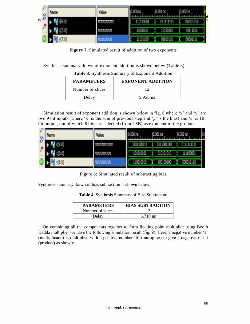
Simulation result of exponent addition is shown below in Fig. 7 where ‘x’ and ‘y’ are two 8
bit inputs (for adding exponent part of multiplier and multiplicand) and ‘s’ is 9 bit output (for
their sum). This step is one part of finding the exponent of the product. In the next part, bias is
to be subtracted from the sum of this part to yield the final result.
International Journal of Applied Sciences and Management ISSN 2413-3396 Vol. 1, no. 1, 48-62, 2015
60 Int. j. appl. sci. manag.
Figure 7. Simulated result of addition of two exponents
Synthesis summary drawn of exponent addition is shown below (Table 3):
Table 3. Synthesis Summary of Exponent Addition
PARAMETERS EXPONENT ADDITION
Number of slices 12
Delay 5.955 ns
Simulation result of exponent addition is shown below in fig. 8 where ‘x’ and ‘y’ are
two 9 bit inputs (where ‘x’ is the sum of previous step and ‘y’ is the bias) and ‘s’ is 10
bit output, out of which 8 bits are selected (from LSB) as exponent of the product.
Figure 8: Simulated result of subtracting bias
Synthesis summary drawn of bias subtraction is shown below:
Table 4. Synthesis Summary of Bias Subtraction
PARAMETERS BIAS SUBTRACTION
Number of slices 13
Delay 5.710 ns
On combining all the components together to form floating point multiplier using Booth
Dadda multiplier we have the following simulation result (fig. 9). Here, a negative number ‘a’
(multiplicand) is multiplied with a positive number ‘b’ (multiplier) to give a negative result
(product) as shown:

ISSN 2413-3396 International Journal of Applied Sciences and Management (IJASM) Vol. 1, no. 1, 45-59, 2015
61
Figure 9. Simulated result of a positive and negative number
Synthesis summary drawn of FPM using Booth Dadda multiplier is shown below:
Table 5. Synthesis Summary of FPM Using Proposed Multiplier
PARAMETERS FPM USING PROPOSED MULTIPLIER
Number of slices 869
Delay 16.254 ns
5. Comparison Comparison of proposed multiplier (Booth (Radix-4) Dadda multiplier) with other multipliers
(Dadda, Wallace, Booth (radix-2), Booth (radix-4), etc), on the basis of number of slices and
delay in ns is shown in Table 6.
Table 6. Comparison Of Proposed Multiplier With Other Multipliers
MULTIPLIER No. of slice LUTs Delay (ns)
Proposed Multiplier 864 14.708
Dadda Multiplier [5] 1,146 -
Existing FPM [5] 1,110 -
Shift Add Multiplier [8] 1,898 -
Radix-4 Booth multiplier [8] 1,886 -
Radix-4 Multiplier (8X8) [7] 213 29.198
Radix-2 Multiplier (8X8) [7] 300 37.881
6. Conclusion
In this paper, basics of floating point number are discussed. Then, the format in which
these numbers are represented is discussed. Then the algorithm related to floating point
multiplier is discussed. In the algorithm, out of the many steps, change was made in a
single step that is mantissa multiplication. Rest of the algorithm is used as it is. It must
be noted that more the number of slices, more will be the area that will be occupied.
Lower the delay, faster will be the operation. Proposed multiplier is simulated using
VHDL and synthesized in Xilinx ISE Design Suite 13.2 and it is found that the
proposed multiplier is better than the other conventional multiplier namely Dadda
International Journal of Applied Sciences and Management ISSN 2413-3396 Vol. 1, no. 1, 48-62, 2015
62 Int. j. appl. sci. manag.
multiplier, Wallace multiplier, Booth (radix-4) multiplier and Booth (radix-2) multiplier
in terms of area occupied and speed. The work can further be extended for Radix- 8 or
higher Booth Multipliers.
References [1] R. K. Saxena, S. Neelam and A. K Wadhwani, “Design of Fast Pipelined Multiplier using
Modified Redundant Adder”, Int. J. Intelligent Syst. Applicat. (IJISA), vol. 4, no.4, pp. 47-53, 2012.
[2] G. A. Lopez, M. Taufer and P. J. Teller, “Evaluation of IEEE 754 Floating Point Arithmetic Compliance Across a Wide Range of Heterogenous Computers”, in Proc. Conf. on Diversity in computing, TAPIA’07, New York, USA, 2007.
[3] K. Khare, R.P. Singh and K. Nilay, “Comparison of pipelined IEEE-754 standard floating point
multiplier with unpipelined multiplier” J. Scientific & Ind. Research, vol. 65, pp. 900-904, Nov.
2006.
[4] M. Al-Ashrafy, A. Salem and W. Anis, "An efficient implementation of floating point
multiplier", in Proc. Electronics, Communications and Photonics Conf. (SIECPC), 2011 Saudi
International IEEE, Riyadh, 2011.
[5] B. Jeevan, S. Narender, C.V. K. Reddy and K. Sivani, “A High Speed Binary Floating Point
Multiplier Using Dadda Algorithm”, in Proc. Automation, Computing, Communication, Control
and Compressed Sensing (iMac4s), International Multi-Conference of IEEE, Kottayam, 2013.
[6] W. L. Pang, K. Y. Chan, S. K. Wong and C. S. Tan, “VHDL Modeling of Booth Radix-4 Floating
Point Multiplier for VLSI Designer’s Library”, Wseas Trans. Syst., vol. 12, no.12, pp. 678-688,
Dec. 2013.
[7] K. Babulu and G.Parasuram,” FPGA Realization of Radix-4 Booth Multiplication Algorithm for
High Speed Arithmetic Logics,” Int. J. Comput. Sci. Inform. Technologies, vol. 2, no. 5, pp. 2102-
2107, 2011.
[8] U. H. Ratneshwar, R. N. Bariya and M. Vishal, “Implementation and Performance Comparison of
Shift-add and Radix-4 Booth Multiplication for Single Precision Floating Point on Xilinx Using
VHDL”, Int. J. Eng. Research and Applicat., vol. 3, no. 3, pp.436-438, May-Jun. 2013.