DESIGN AND IMPLEMENTATION OF FIRE ALARM CONTROL FOR …
10
GSJ: Volume 7, Issue 11, November 2019, Online: ISSN 2320-9186 www.globalscientificjournal.com DESIGN AND IMPLEMENTATION OF FIRE ALARM CONTROL FOR REMOTE INDUSTRIAL PLANT Diamond Ebegba Department of Electrical and Electronic Engineering Petroleum Training Institute, Effurun Delta State, Nigeria. [email protected] KeyWords Alarm, Water Sprinkler, SMS notification, emergency, embedded system. ABSTRACT The important side of fire protection is to pin point a developing fire emergency in an exceedingly timely manner, and to alert the building's occupants and fire service organizations. This is the function of fire detection and alarm systems. Depending on the anticipated fire situa- tion, building and use type, number and type of occupants and criticality of contents and mission, this research is about fire alarm with wa- ter sprinkler and SMS alarm. The system can sense developing fire through either manual or automatic methods then it alert building occu- pants to a fire condition and the need to evacuate, also, it sends notification signal to a fire service or other emergency response and it also initiate automatic suppression systems such as water sprinklers. This prototype was built around microcontroller and other electronic com- ponent. it’s cost effective and response in a very fast way. GSJ: Volume 7, Issue 11, November 2019 ISSN 2320-9186 535 GSJ© 2019 www.globalscientificjournal.com
Transcript of DESIGN AND IMPLEMENTATION OF FIRE ALARM CONTROL FOR …

GSJ: Volume 7, Issue 11, November 2019, Online: ISSN 2320-9186 www.globalscientificjournal.com
DESIGN AND IMPLEMENTATION OF FIRE ALARM CONTROL FOR REMOTE INDUSTRIAL PLANT Diamond Ebegba Department of Electrical and Electronic Engineering
Petroleum Training Institute, Effurun Delta State, Nigeria.
KeyWords Alarm, Water Sprinkler, SMS notification, emergency, embedded system.
ABSTRACT
The important side of fire protection is to pin point a developing fire emergency in an exceedingly timely manner, and to alert the building's
occupants and fire service organizations. This is the function of fire detection and alarm systems. Depending on the anticipated fire situa-
tion, building and use type, number and type of occupants and criticality of contents and mission, this research is about fire alarm with wa-
ter sprinkler and SMS alarm. The system can sense developing fire through either manual or automatic methods then it alert building occu-
pants to a fire condition and the need to evacuate, also, it sends notification signal to a fire service or other emergency response and it also
initiate automatic suppression systems such as water sprinklers. This prototype was built around microcontroller and other electronic com-
ponent. it’s cost effective and response in a very fast way.
GSJ: Volume 7, Issue 11, November 2019 ISSN 2320-9186
535
GSJ© 2019 www.globalscientificjournal.com

INTRODUCTION
Vandalized or environmentally damaged structures can be repaired and stolen objects recovered. Items destroyed by fire, however,
are gone forever. An uncontrolled fire can obliterate an entire room's contents within a few minutes and completely burn out a
building in a couple hours.
Henry S. Parmalee, Connecticut is the first inventor of the automatic sprinkler head. Parmalee modified the Pratt patent and created
a better sprinkler system. In 1874, he installed his fire sprinkler system into the piano company that he owned. Frederick Grin-
nell modified Parmalee's design and in 1881 patented the sprinkler system that bears his name. He continued to modify the system
and in 1890 invented the glass disc sprinkler, essentially the same as that in use today.
Until the 1940s, sprinklers were installed almost exclusively for the protection of commercial buildings, whose owners were general-
ly able to recoup their expenses with savings in insurance costs. Over the years, fire sprinklers have become mandatory safety
equipment in some parts of North America, in certain occupancies, including, but not limited to newly constructed hospitals,
schools, hotels and other public buildings, subject to the local building codes and enforcement. However, outside of the US and Can-
ada, sprinklers are rarely mandated by building codes for normal hazard occupancies which do not have large numbers of occupants
(e.g. factories, process lines, retail outlets, petrol stations, etc.)
Sprinklers are now commonly installed in buildings like schools, industrial and residential premises. This is largely as a result of sensi-
tization.
In Scotland, all new schools are sprinkler protected, as are new care homes, sheltered housing and high rise flats. In England all high
rise buildings over 30m must have sprinkler protection. In 2011 Wales became the first country in the world to make installation of
fire sprinklers in new homes compulsory. The law will apply to newly built houses and blocks of flats, as well as care homes and uni-
versity halls of residence. This law will be enforced from September 2013.
Goals and Specific Objectives
The goal of this project work is to successfully come up with a designed and constructed device that can be used to monitor fire oc-
currence in a building and also activate a water sprinkler to suppress the source of fire automatically which can be installed in
schools, dormitories, churches, offices, industries and so on.
And the specific objective of this work is to design and construct a fire alarm system and a sprinkler which can;
1. Detect fire occurrence in a building and activating an alarm.
2. Activate a water sprinkler on sensing any fire occurrence in the building.
GSJ: Volume 7, Issue 11, November 2019 ISSN 2320-9186
536
GSJ© 2019 www.globalscientificjournal.com

System block diagram
Input Signal Fire/Smoke Sensor CPU/Controller
Power Supply Unit
GSM Module Indicator And Actuator
Fig 1: System Block Diagram
1. Power Supply Unit
This unit is very important in this circuit as it provides the required voltage needed for the circuit to function, the unit is consist of
various component such as transformer, bridge diode , capacitor, voltage regulator etc. In other words this unit is used for powering
the circuit.
2. Sensor
This is the unit responsible for sensing smoke or fire and to convert it into a digital signal which is then given as an input signal to the
microcontroller unit to act upon. The sensor unit can be achieved by putting various components together such as LDR and led or
better still obtaining an already made fire and smoke sensor module from the market.
3. Microcontroller unit:
The microcontroller unit is the heart of this project, in the sense that it takes in input signal which comes from the sensors unit, act
upon it and give a decision on what to do depending on the state of the input signal either to turn on the indicator or turn on the
actuator which will suppress the fire. This unit functions to give a proper control to this work by working on the code inputted on it
by the programmer to take input commands, decide on it and to take a decision on what to do depend on what the input signal is.
The code is written on c programming language and the microcontroller used is pic16f877a. Other components used to configure
the microcontroller are crystal, non-polarized capacitor etc.
4. GSM Unit
This unit serves the purpose of alerting the appropriate quarters when there is a fire event. It can be implemented with any GSM
Module with serial communication interface.
5. Actuator and Indicator Unit
This unit is the output unit of the device. The indicator is used to notify users that there is a fire out break and the device used for
the indicator can be a lamp for visual notification or can be an alarm for audio notification. The actuator on the other hand is used to
control the pump supplying the water used for suppressing the fire. It can be a solenoid valve or a switch used to control the pump.
II. DESIGN METHODOLOGY
The battery operated fire alarm with water sprinkler and GSM Alert was sub-divided into various unit for easy and efficient imple-
mentation
GSJ: Volume 7, Issue 11, November 2019 ISSN 2320-9186
537
GSJ© 2019 www.globalscientificjournal.com

THE SENSOR UNIT
This unit detects the presence of smoke or fire fumes.
Requirement of the Sensor Unit
The sensor should be able to effectively detects fire or smoke fumes
Should have easy communication interface compatible with microcontrol-
lers.
Should be easily biased
Should have low power requirement because the design is battery operated.
Fig 2: Microcontroller and Smoke Sensor Interface
The Water Sprinkler Unit
This unit when activated sprinkles water into the confined space where the smoke or fire is detected. It was implemented with a
220V AC water Pump, bc547 NPN transistor, 12V 10A DC Relay, diode, resistor and a water reservoir. Below is the circuit diagram of
the Water sprinkler unit.
RA0/AN02
RA1/AN13
RA2/AN2/VREF-/CVREF4
RA4/T0CKI/C1OUT6
RA5/AN4/SS/C2OUT7
RE0/AN5/RD8
RE1/AN6/WR9
RE2/AN7/CS10
OSC1/CLKIN13
OSC2/CLKOUT14
RC1/T1OSI/CCP216
RC2/CCP117
RC3/SCK/SCL18
RD0/PSP019
RD1/PSP120
RB7/PGD40
RB6/PGC39
RB538
RB437
RB3/PGM36
RB235
RB134
RB0/INT33
RD7/PSP730
RD6/PSP629
RD5/PSP528
RD4/PSP427
RD3/PSP322
RD2/PSP221
RC7/RX/DT26
RC6/TX/CK25
RC5/SDO24
RC4/SDI/SDA23
RA3/AN3/VREF+5
RC0/T1OSO/T1CKI15
MCLR/Vpp/THV1
U3
PIC16F877A
RL112V
Q1BC547
R1
10k
WATER PUMP
C
NONC
To 12V VCC
D2DIODE
Fig. 3: Interface between the microcontroller and the Water Sprinkler Unit
This unit connects directly with the microcontroller through PIN 33. When the microcontroller detects smoke or fire fumes through
the GH312 Smoke sensor it activates the transistor to energies the Relay in-turn giving power to the water pump motor to sprinkle
water from the reservoir to the confined space.
GH312 (Smoke Sensor)
RA0/AN02
RA1/AN13
RA2/AN2/VREF-/CVREF4
RA4/T0CKI/C1OUT6
RA5/AN4/SS/C2OUT7
RE0/AN5/RD8
RE1/AN6/WR9
RE2/AN7/CS10
OSC1/CLKIN13
OSC2/CLKOUT14
RC1/T1OSI/CCP216
RC2/CCP117
RC3/SCK/SCL18
RD0/PSP019
RD1/PSP120
RB7/PGD40
RB6/PGC39
RB538
RB437
RB3/PGM36
RB235
RB134
RB0/INT33
RD7/PSP730
RD6/PSP629
RD5/PSP528
RD4/PSP427
RD3/PSP322
RD2/PSP221
RC7/RX/DT26
RC6/TX/CK25
RC5/SDO24
RC4/SDI/SDA23
RA3/AN3/VREF+5
RC0/T1OSO/T1CKI15
MCLR/Vpp/THV1
U3
PIC16F877A
To 5V VCC
signal
GSJ: Volume 7, Issue 11, November 2019 ISSN 2320-9186
538
GSJ© 2019 www.globalscientificjournal.com

Selection of the transistor
The choice of Q1 depends on the following parameters:
The nature of the actuating signal (control signal).
The load current demand (collector current)
The supply voltage.
The relay current (load current)= Relay voltage/ Relay resistance
Relay voltage=12V (specified)
Relay Resistance= 120Ω (observed)
Relay current demand= 12v/120 =0.1A i.e. 100mA.
Relay current=transistor collector current.
From the bc547 datasheet, Ic (sat) = 400mA > 100mA (load).
Hfe= 100 to 150; using a Hfe of 120
Vbe=0.7v.
The Alarm Unit
This unit gives an audible alert when a smoke or fire fumes is detected. It was implemented with a 5v DC buzzer connected and con-
trolled by the microcontroller. It was biased with a 10k resistor to limit current from the controller to the buzzer. Below is the inter-
face between the buzzer and the microcontroller.
ALARM UNIT
DC BUZZER
DO
Q2BC547
R2
10k12V
RA0/AN02
RA1/AN13
RA2/AN2/VREF-/CVREF4
RA4/T0CKI/C1OUT6
RA5/AN4/SS/C2OUT7
RE0/AN5/RD8
RE1/AN6/WR9
RE2/AN7/CS10
OSC1/CLKIN13
OSC2/CLKOUT14
RC1/T1OSI/CCP216
RC2/CCP117
RC3/SCK/SCL18
RD0/PSP019
RD1/PSP120
RB7/PGD40
RB6/PGC39
RB538
RB437
RB3/PGM36
RB235
RB134
RB0/INT33
RD7/PSP730
RD6/PSP629
RD5/PSP528
RD4/PSP427
RD3/PSP322
RD2/PSP221
RC7/RX/DT26
RC6/TX/CK25
RC5/SDO24
RC4/SDI/SDA23
RA3/AN3/VREF+5
RC0/T1OSO/T1CKI15
MCLR/Vpp/THV1
U4
PIC16F877A
Fig 4: interface between microcontroller and alarm unit
3.2.5 THE GSM UNIT
Thus unit enables the system send CALL/SMS alert indicating fire alert. SIMCOM900 GSM modem is used here to send SMS contain-
ing the notification about the fire Alert. The microcontroller detects the HIGH signal from the GH312 fire sensor and process it, then
GSJ: Volume 7, Issue 11, November 2019 ISSN 2320-9186
539
GSJ© 2019 www.globalscientificjournal.com
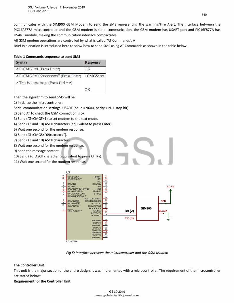
communicates with the SIM900 GSM Modem to send the SMS representing the warning/Fire Alert. The interface between the
PIC16F877A microcontroller and the GSM modem is serial communication, the GSM modem has USART port and PIC16F877A has
USART module, making the communication interface compactable.
All GSM modem operations are controlled by what is called “AT Commands”. A
Brief explanation is introduced here to show how to send SMS using AT Commands as shown in the table below.
Table 1 Commands sequence to send SMS
Then the algorithm to send SMS will be:
1) Initialize the microcontroller:
Serial communication settings: USART (baud = 9600, parity = N, 1 stop bit)
2) Send AT to check the GSM connection is ok
3) Send (AT+CMGF=1) to set modem to the text mode.
4) Send (13 and 10) ASCII characters (equivalent to press Enter).
5) Wait one second for the modem response.
6) Send (AT+CMGS=”09xxxxxxxx”).
7) Send (13 and 10) ASCII characters.
8) Wait one second for the modem response.
9) Send the message content.
10) Send (26) ASCII character (equivalent to press Ctrl+z).
11) Wait one second for the modem response.
RA0/AN02
RA1/AN13
RA2/AN2/VREF-/CVREF4
RA4/T0CKI/C1OUT6
RA5/AN4/SS/C2OUT7
RE0/AN5/RD8
RE1/AN6/WR9
RE2/AN7/CS10
OSC1/CLKIN13
OSC2/CLKOUT14
RC1/T1OSI/CCP216
RC2/CCP117
RC3/SCK/SCL18
RD0/PSP019
RD1/PSP120
RB7/PGD40
RB6/PGC39
RB538
RB437
RB3/PGM36
RB235
RB134
RB0/INT33
RD7/PSP730
RD6/PSP629
RD5/PSP528
RD4/PSP427
RD3/PSP322
RD2/PSP221
RC7/RX/DT26
RC6/TX/CK25
RC5/SDO24
RC4/SDI/SDA23
RA3/AN3/VREF+5
RC0/T1OSO/T1CKI15
MCLR/Vpp/THV1
U3
PIC16F877A
SIM900Rx (2)
Tx (3)
RED
BLACK
TO 5V
Fig 5: Interface between the microcontroller and the GSM Modem
The Controller Unit
This unit is the major section of the entire design. It was implemented with a microcontroller. The requirement of the microcontroller
are stated below:
Requirement for the Controller Unit
GSJ: Volume 7, Issue 11, November 2019 ISSN 2320-9186
540
GSJ© 2019 www.globalscientificjournal.com

- Be able to detect high and low level from the GH312 smoke sensor
- Should have internal ADC module to interface the fully charge circuit of the battery charger
- Should have enough I/O pins to bias the entire components of the design.
- Should have internal USART communication module necessary to interface the sim900 GSM modem.
- Should be affordable, easily programmed and low power requirement.
The pic16f877a microcontroller from Microchip Corporation was used. BELOW IS The Brief Operation Of the Microcontroller Unit:
- Waits For High Level Signal (5v) From The Sensor Unit
- When The High Level Is Detected, Puts High (5v) At Pin33 To Activate The Water Sprinkler Pump.
- Puts High (5v) At Pin44 To Activate The Buzzer Alarm.
- Puts the AT Commands at Pin25 and Pin26 to Communicate with the GSM Modem to Send CALL/SMS Alert.
The microcontroller was connected to 8MHZ crystal biased with two 15pf capacitors as specified by in the datasheet.
RA0/AN02
RA1/AN13
RA2/AN2/VREF-/CVREF4
RA4/T0CKI/C1OUT6
RA5/AN4/SS/C2OUT7
RE0/AN5/RD8
RE1/AN6/WR9
RE2/AN7/CS10
OSC1/CLKIN13
OSC2/CLKOUT14
RC1/T1OSI/CCP216
RC2/CCP117
RC3/SCK/SCL18
RD0/PSP019
RD1/PSP120
RB7/PGD40
RB6/PGC39
RB538
RB437
RB3/PGM36
RB235
RB134
RB0/INT33
RD7/PSP730
RD6/PSP629
RD5/PSP528
RD4/PSP427
RD3/PSP322
RD2/PSP221
RC7/RX/DT26
RC6/TX/CK25
RC5/SDO24
RC4/SDI/SDA23
RA3/AN3/VREF+5
RC0/T1OSO/T1CKI15
MCLR/Vpp/THV1
U3
PIC16F877A
8MHZCRYSTAL
C2
15uF
C3
15uF
Fig 6: The Microcontroller Section
GSJ: Volume 7, Issue 11, November 2019 ISSN 2320-9186
541
GSJ© 2019 www.globalscientificjournal.com

Vdd Vss
11 12
16MHZCRYSTAL
ALARM UNIT
DC BUZZER
C2
15uF
C3
15uF
RA0/AN02
RA1/AN13
RA2/AN2/VREF-/CVREF4
RA4/T0CKI/C1OUT6
RA5/AN4/SS/C2OUT7
RE0/AN5/RD8
RE1/AN6/WR9
RE2/AN7/CS10
OSC1/CLKIN13
OSC2/CLKOUT14
RC1/T1OSI/CCP216
RC2/CCP117
RC3/SCK/SCL18
RD0/PSP019
RD1/PSP120
RB7/PGD40
RB6/PGC39
RB538
RB437
RB3/PGM36
RB235
RB134
RB0/INT33
RD7/PSP730
RD6/PSP629
RD5/PSP528
RD4/PSP427
RD3/PSP322
RD2/PSP221
RC7/RX/DT26
RC6/TX/CK25
RC5/SDO24
RC4/SDI/SDA23
RA3/AN3/VREF+5
RC0/T1OSO/T1CKI15
MCLR/Vpp/THV1
U1
PIC16F877A
RL112V
Q1BC547
R1
10k
SIM900
WATER PUMP
GH312 (Smoke Sensor)
TR1
230v/15v step down Trans
BR1
BRIDGE C11000uf
25v
C
NO
NC
Rx (2)
Tx (3)D1 D2
D3D4
RED
BLACK
VI1
VO3
GN
D2
U27805
TR1
230v/15v step down Trans
BR1
BRIDGE C11000uf
25v
D1 D2
D3D4
VI1
VO3
GN
D2
U27805
NUETRAL (AC)
LIVE (AC)
GND
DO
VCC
T1IN11
R1OUT12
T2IN10
R2OUT9
T1OUT14
R1IN13
T2OUT7
R2IN8
C2+
4
C2-
5
C1+
1
C1-
3
VS+2
VS-6
U3
MAX232
C4
1nF
C5
1nF
C61nF
C7
1nF
C8104
C9104
C10104
Q2BC547
R2
10k12V
R310k
GSJ: Volume 7, Issue 11, November 2019 ISSN 2320-9186
542
GSJ© 2019 www.globalscientificjournal.com

Flow Chart
The flow chart gives a graphical representation of the sequence of program execution. The flow chart is given below:
Testing and Result
The completed project as stated in the problem statement was tested to confirm if it could provide solution to the stated problems
GSJ: Volume 7, Issue 11, November 2019 ISSN 2320-9186
543
GSJ© 2019 www.globalscientificjournal.com
Conclusion
A successful attempt has been made to design and implement a fire alarm system with SMS alert using locally available material. The
system is capable of enhancing the alert when there is a fire outbreak. The completed work had been tested and worked satisfactory.
A research approach was adopted in the implementation of this system, from whence a workable circuit was designed. The design
was done using embedded system technology. This is to keep the system simple and cost effective. Furthermore, the project work
has enabled me to apply engineering knowledge in solving everyday problem.
Acknowledgment
This research work was supported by the staff and students of Electrical and Electronic Engineering Department, Petroleum Training
Institute, Effurun.
References
[1] Ahmed, Abdalsalam & Mansor, Abdulsalam & Albagul, Abdulgani. (2015). Design and Fabrication of an Automatic Sprinkler Fire Fighting System.
Lecture Notes in Control and Information Sciences. 789. 10.1007/978-3-319-17527-0_5..
[2] Tharaja B. L, Tharaja A. K. (2001), A Text Book of Electrical Technology, S. Chand & Company Ltd. New Delhi INDIA 22nd Edition, P. 1730 – 1731
[3] Boylestad and Nashelsky (2007). “Electronics Device and Circuit Theory” (Ninth edition)
[4] Bernard Grob “Electronics Circuits and Applications” First Edition 2006.
[5] 6. www.alldatasheets.com
[6] Inan Sinclair and John Dunton, (2007) “Practical Electronics Handbook, Sixth Edition.
GSJ: Volume 7, Issue 11, November 2019 ISSN 2320-9186
544
GSJ© 2019 www.globalscientificjournal.com