Design and Implementation of a Graphical User … and Implementation of a Graphical User Interface...
47
Design and Implementation of a Graphical User Interface for Elektra Raffael Pancheri 0003088 March 26, 2015 Abstract Nowadays the graphical user interface is very popular and widespread on computer sys- tems, so many users expect a graphical user interface when using a software, especially inexperienced users. However, in 2014 Elektra, a multi-platform configuration management software, did only offer a text-based user interface. The goal of this thesis was to design and implement a graphical user interface that provides high usability to make Elektra eas- ier to use for existing - and to attract new - users. To achieve this goal, the design and implementation was based on a number of compiled requirements, use cases and design guidelines. The interface was implemented with the Qt Quick module, which is a part of the C++ based Qt framework. The implementation proved to be challenging, since Qt Quick is still in development and does not carry as many features as the more mature Qt Widgets module. To verify that the goal of high usability had indeed been reached, the software was evaluated with the System Usability Scale questionnaire in a laboratory environment. The results were encouraging, 50% considered the graphical user interface Excellent or better on the System Usability Scale adjective scale. 1 Introduction The user interface (UI) is an essential part of every computer application. Many users do not distinct between a system and the accompanied interface since the sophisticated logic that allows the application to do its purpose cannot be seen. So the part that the user can see is perceived as the application itself, rendering the user interface thatf important. Since the UI is so cruicial to every software, it is obvious that an user interface should be designed with great care. A computer application, how adequate and convenient it might be to solve the problem it was programmed for, will be rejected by the user if it cannot be used in a satisfactory way. The Graphical User Interface (GUI) has gained massive popularity since Apple introduced the first mass-market system with this kind of UI in the 1980s. Although GUIs did not fully replace the common text based interfaces, nowadays the majority of users, especially users who are not familiar with a software, expect to be offered a graphical user interface. Elektra is a multi-platform configuration management library. In 2014, when this thesis was started, Elektra was only equipped with a text-based Command Line Interface (CLI). While this kind of UI is often favoured by expert users, the CLI is generally considered to have a steep learning curve and might discourage new users who would otherwise have had an interest in the software. The goal and purpose of this thesis was to design and implement a graphical user 1
Transcript of Design and Implementation of a Graphical User … and Implementation of a Graphical User Interface...

Design and Implementation of a Graphical User
Interface for Elektra
Raffael Pancheri
0003088
March 26, 2015
Abstract
Nowadays the graphical user interface is very popular and widespread on computer sys-tems, so many users expect a graphical user interface when using a software, especiallyinexperienced users. However, in 2014 Elektra, a multi-platform configuration managementsoftware, did only offer a text-based user interface. The goal of this thesis was to designand implement a graphical user interface that provides high usability to make Elektra eas-ier to use for existing - and to attract new - users. To achieve this goal, the design andimplementation was based on a number of compiled requirements, use cases and designguidelines. The interface was implemented with the Qt Quick module, which is a part of theC++ based Qt framework. The implementation proved to be challenging, since Qt Quickis still in development and does not carry as many features as the more mature Qt Widgetsmodule. To verify that the goal of high usability had indeed been reached, the software wasevaluated with the System Usability Scale questionnaire in a laboratory environment. Theresults were encouraging, 50% considered the graphical user interface Excellent or better onthe System Usability Scale adjective scale.
1 Introduction
The user interface (UI) is an essential part of every computer application. Many users donot distinct between a system and the accompanied interface since the sophisticated logic thatallows the application to do its purpose cannot be seen. So the part that the user can see isperceived as the application itself, rendering the user interface thatf important. Since the UI isso cruicial to every software, it is obvious that an user interface should be designed with greatcare. A computer application, how adequate and convenient it might be to solve the problem itwas programmed for, will be rejected by the user if it cannot be used in a satisfactory way.
The Graphical User Interface (GUI) has gained massive popularity since Apple introduced thefirst mass-market system with this kind of UI in the 1980s. Although GUIs did not fully replacethe common text based interfaces, nowadays the majority of users, especially users who are notfamiliar with a software, expect to be offered a graphical user interface.
Elektra is a multi-platform configuration management library. In 2014, when this thesis wasstarted, Elektra was only equipped with a text-based Command Line Interface (CLI). Whilethis kind of UI is often favoured by expert users, the CLI is generally considered to have a steeplearning curve and might discourage new users who would otherwise have had an interest inthe software. The goal and purpose of this thesis was to design and implement a graphical user
1

interface that should provide high usability to make Elektra easier to use for existing, and tobe more attractive to new users.
The goal of creating an usable computer interface is easily missed without a solid concept.Therefore this project rests on two pillars:
Requirements and use-cases 24 functional and non-functional requirements were com-piled and 17 detailed use cases were created to document and describe the intended behaviourof the user interface
Design Guidelines The GUI was designed respecting the laws of human perception aswell as a number of design guidelines and platform specific standards
The GUI was implemented with the Qt Quick module that is part of the C++ based Qtframework. Because Qt Quick is the newest and most current Qt module to create graphicaluser interfaces with, it does not carry as many features as the more mature Qt Widgets module.That is the reason why the implementation proved to be challenging.
To verify that the goal of an user interface with high usability was indeed reached, we evaluatedthe GUI in an usability test in a laboratory environment with the System Usability Scale (SUS)questionnaire. The test showed that half of the probands rated the interface as Excellent orbetter on the SUS adjective scale, proving that respecting fundamental principles of design canindeed lead to well usable computer interfaces.
This thesis is structured as follows: In Section 2 we will introduce Elektra and discuss theconcept of usability and basic characteristics of CLIs and GUIs. Section 3 will familiarizethe reader with some rules and guidelines that should be respected when designing computerinterfaces. Requirements and use cases will be considered in Section 4. The technology used toimplement the application as well as some notable implementation issues will be brought up inSection 5, followed by the evaluation of the GUI in Section 6. The conclusion will complete thethesis.
2 Background
2.1 Elektra
Figure 1 – Elektra’s Logo [22]
Elektra is a library implementing access to a global keydatabase [22]. Its source code and additional information canbe found on the project’s website www.libelektra.org. Atthe time of writing this thesis Elektra is available in version0.8.11.
Elektra was developed to address problems that existing con-figuration management systems (e.g kconfig, gconfig, WindowsRegistry) faced. Theses already existing solutions neither hideplatform specific behaviour nor abstract1 from the platformenvironment’s details. The lacking abstraction leads to thefact that the software is strictly bound to the surrounding
1Abstraction in this context means that the applications that are using Elektra to store their configurationdo not know anything about how and where the settings are actually stored.
2

desktop and/or operating system and therefore not platform independent, which limits theirfield of application.
To avoid the problem of lacking portability Elektra has a modular design. The library consistsof a small independent core written in C and is due to the language’s wide distribution availableon almost all computer systems. To deal with system specific details and to achieve abstractionthe library core is extendable with plugins, each created for a specific task. It is in theseplugins where the system specific behaviour as well as the abstraction happens. Contrary toearlier versions of Elektra (< 0.8), the user can select which plugins should be compiled and,by choosing only required plugins, reduce unnecessary overhead. Plugins can use other pluginsif a certain task is already implemented, allowing code reuse.
For a software application to be able to actually use Elektra it needs to be modified (so calledelektrified). Once elektrified, each application is able to access configuration from other elektri-fied applications.
Implementation wise, Elektra essentially consists of three base classes:
Key A Key consists of a name, a value and metadata. A Key object can hold an unlimitedamount of metadata in the form of metakeys, providing information about the Key. A Key
can be serialised and thus be stored permanently. Each Key is absolute and independentfrom other Keys.
KeySet A KeySet holds Key objects and represents a configuration. Every Key in a KeySethas a unique name. A KeySet sorts its Keys by their name. KeySets can be extended byadding Keys to, and reduced by popping Keys from KeySets. KeySets can be iterated over,updated, modified, extended and reduced. The same Key object can exist in more than oneKeySet.
KDB The KDB class provides access to the global key database. Through this class anelektrified application is able to get stored configuration from the global database, modifythe resulting KeySet and store the altered configuration back to the global database. Anelektrified application is able to modify its configuration settings in memory without alteringthe global database until writing the modified KeySet back.
2.2 Usability
A central component of the development of the GUI was to ensure high usability. There existseveral definitions of usability (e.g. ISO 9241, [8], [26]), but in this thesis the term is usedas defined by Nielsen in [19]. According to Nielsen’s definition, usability consists of five at-tributes:
Learnability The system should be easy to learn.
Efficiency The system should be efficient to use.
Memorability The system should be easy to remember.
Errors The system should have a low error rate.
Satisfaction The system should be pleasant to use.
To increase the probability to design a GUI with high usability, Jakob Nielsen suggests a modelthat consists of eleven steps, but he admits that for a successful project it is not necessary to
3

include every stage [19, p. 72].
Since this thesis and the corresponding implementation of the GUI was executed by a singleindividual in a rather limited time frame (contrary to a team of developers that consists ofprogrammers, graphical designers, etc.), the author reduced Nielsen’s model to the followingessential key points:
Know the User At the start of every project rise certain questions that are needed to beanswered, like the characteristics (age, education level, experience with computer systems ingeneral,...) of the target audience and the goals that these users want to achieve by using theapplication. However, since Elektra is not widespread as configuration management solutionat the moment, the amount of “real-life” users is limited and it was therefore difficult forthe author to get hold of such individuals. So the person most involved in creating a userprofile was the maintainer and main developer of Elektra, Markus Raab2. With his help therequirements of the GUI were compiled (see Section 4).
Guidelines Many guidelines exist for designing user interfaces, either in general (e.g. [26,Chapter 2]) or specialized to a platform (e.g. [14], [21], [10]). We designed the softwarerespecting design guidelines proposed by Ben Shneiderman, Don Norman and Jakob Nielsenas well as the basic principles of Gestalt Theory (see Section 3).
Prototyping Before starting to implement actual code it is of utmost importance to pro-totype a GUI [6]. These prototypes can include paper mockups as well as low/high levelsoftware prototypes which allow interaction without deeper functionality. The author chosethe mockup software Pencil3 to create interactive wireframe prototypes (see Section 5).
Iterative Design This principle is especially used in, but not limited to, the early projectstages when prototypes are presented to the user and changes based on the user evaluationwill be integrated in the next iteration step of the prototype. The number of changes of theprototypes generally decreases with the increase of the number of iterations. There were fourversions of the wireframe prototype and countless minor and major changes in the design ofthe interface before the final version was completed.
2.3 Types of User Interfaces
The evolution of computers from their invention until today cannot be narrowed down to im-provements in hardware alone. Along with the rise of computing power in the last 50 years wenta change in the type of computer users and the way these users interacted with machines. Table1 shows an overview of the milestones in computer history that mark the generations in hard-ware development and the according changes in user types and user interfaces. In this thesisonly generation two and four are of interest since only these two are relevant to Elektra.
2.3.1 Command Line Interface (Generation 2)
Line oriented interfaces were introduced around 1960 with the purpose to allow multiple usersaccess to a single mainframe computer [19] and are an essential method of HCI until today.
Before this thesis was started, the only way to interact with Elektra was by prompting commandsinto a typical one dimensional line-oriented shell interface. One dimensional in this context
[email protected]://pencil.evolus.vn/
4

Generation User Types User Interface Paradigm
0 (until 1945) The inventors themselves None
1 (1945-1955) Experts, Pioneers Programming, Batch
2 (1955-1965) Technocrats, Professional computer-ists
Command Languages
3 (1965-1980) Specializes groups without computerknowledge
Full-screen strictly hierarchical menusand form fill-in
4 (1980-1995) Business professionals, Hobbyists WIMP (Windows, Icons, Menus anda Pointing device)
5 (1995-?) Everybody Noncommand-based interfaces
Table 1 – Summary of the generations of computers and user interfaces (based on [19,p50])
means, that the user is only able to modify the last line on the screen, once she hits enter,the input cannot be changed any further. Similarly, the computer output is static and doesnot reflect any changes in the data that might have happened in the background since the lastinteraction. This way of HCI requires the user to know
• the available commands and parameters (approximately 80 in case of Elektra)
• exactly when to use these commands and parameters (in contrast to guessing and explor-ing)
• the exact syntax of these commands (one single spelling error is enough and the commandwill fail)
and is therefore putting a substantial cognitive load on the user. Especially for novice users aCLI can be challenging as it generally provides a steep learning curve [11, p. 414]. Additionally,a CLI does not support multitasking very well as the whole screen is focused on one singleapplication.
On the other side, the command line offers much more flexibility to the advanced user byoffering the possibility to chain commands and to enable complex and powerful manipulationswith relatively little effort in relatively little time. A CLI can practically be supplied on everycomputerized device because it has very low demands regarding CPU, RAM and screen.
2.3.2 Graphical User Interface (Generation 4)
A GUI is composed of elements that can be described with the acronym WIMP: Windows,Icons, Menus and a Pointing device. Although the first GUI that included all elements weassociate with modern graphical interfaces was invented in 1973 with the Xerox Alto, it was notuntil 1984 that GUIs gained massive popularity with the release of the Apple Macintosh [9].Key element is the concept of the pointing device, acting as a virtual extension of the physicalhand and thus enabling the user to “touch” the icons and menus on the screen.
By further adding metaphors to screen design that are familiar to the user from everyday life(like the “Desktop” metaphor), a modern GUI is considered to be intuitive and natural to a
5
novice user, enabling her to explore and try out the environment. A GUI is very well suited formultitasking, allowing the user to switch between and work on several open windows, foldersand applications simultaneously.
As novice users can have difficulties to get accustomed to a CLI, expert users might find GUIscumbersome and impractical to use since they generally offer less options than the CLI coun-terpart and often do not support to chain actions or scripting in general. A GUI is harder totest and to design for developers since it is more complex and has higher demands regardinghardware to function fluidly.
2.3.3 When is a GUI desirable?
As mentioned before, a general agreement among most interface specialists is that GUIs havebetter usability characteristics than character based interfaces, especially in respect to learn-ability for novice users [19]. Despite the fact that there are several studies that show that usersare able to solve the same test tasks in less time and with fewer errors when using a GUI incomparison to a text base interface (e.g. [16], [23]), a general statement that graphical userinterfaces are better usable than text based interfaces is not possible (a low quality GUI canstill be inferior in usability to a CLI). If a GUI or a CLI is more usable highly depends on thetask to solve. Image drawing, for example, is due to its visual nature hard to imagine without aGUI, while renaming the file ending JPG to jpg of 10 000 image files in a folder without a CLI,where this action can be achieved in a single command, would be exceptionally painful. So, ananswer to the question if a GUI is desirable or not is not possible without examination of therange of application.
Elektra enables users access to a hierarchical database. A text-based interface is not the idealmedium to display hierarchical data. A tree, although by no means the only way to visualizehierarchical structures, is much more useful for this task, allowing the viewer to understandthe structure and distribution of the data. A tree is also an ideal data structure to allowexploration, a task which is supported, as mentioned before, as an inherent feature of graphicaluser interfaces.
In Figure 2 we see a comparison of Elektra’s existing command line interface with the graphicaluser interface of Elektra Editor. Both interfaces are displaying the same data. While in the GUIthe number and names of the items below the root node are grasped instantly by the viewer,the CLI requires the user to read and cognitively process the visual information to finally cometo the conclusion, that the root node has exactly four direct children. Further, the CLI displaysall data even though one might not be interested to see every entry in the database4.
To edit a key, a person using the GUI can open a window that allows to change name, valueand metadata of a key in one step, while a user of the CLI needs to prompt three differentcommands to change the according properties. The same is true for creating keys, instead ofthe necessity to prompt two separate commands in order to create a key with a name, a valueand a metakey in the CLI, the GUI user can achieve this goal in a single working step.
In conclusion, the author considers working with Elektra an application that is well suited tobe complemented by a graphical user interface. Not only can many tasks be solved in less stepsin a graphical environment, the existence of a GUI is further a proper way to attract novices touse Elektra by reducing the potential fear of the inexperienced user of the command line andthus helping to increase the proliferation of Elektra.
4Wills calls this information overload [28]
6

$ kdb l s useruser /branch1/key1user /branch1/key2user /branch1/key3user /branch1/key4user /branch1/key5user /branch1/key6user /branch1/key7user /branch2user /branch3/ subbranch31/keyuser /branch4user /branch4/#0user /branch4/#1user /branch4/#2user /branch4/#3user /branch4/#4user /branch4/#5user /branch4/#6user /branch4/#7user /branch4/#8user /branch4/#9user /branch4/# 10user /branch4/# 11user /branch4/# 12
(a) The output of the command kdb ls user (b) The user subtree viewed in Elektra Editor
Figure 2 – CLI vs GUI: the hierarchical key database
3 Basic Principles of Visual Design
In order to successfully design a GUI it is advisable to make oneself familiar with the basicprinciples of visual design. These include general guidelines to interface design, the awarenessof the existence of Gestalt Theory and its indications on human perception as well as some basicknowledge about color. Finally, dependent of the target platform, it can be of use to consultthe according human interface guidelines, if certain questions like the arrangement of buttonsor the size of margins arise. There exist, among others, platform specific design guidelines forMicrosoft Windows [7], Mac OSX [21] and KDE [14].
3.1 Guidelines
Ben Shneiderman proposes the “eight golden rules of interface design” [26]:
Strive for Consistency Identical terminology should be used throughout the application,e.g. in prompts, menus and help screens. Also there should be a consistent use of color,layout, capitalization, fonts, etc.
Cater to universal usability The purpose here is to recognize the needs of diverse users.Diverse here means consideration of novice-expert differences (e.g. adding help text fornovice users and shortcuts for expert users), age ranges or disabilities.
Offer informative feedback It is important to ensure the user can see any reaction tohis input, changes should be made visible.
Design dialogs to yield closure Sequences of actions should be organized into groupswith a beginning, middle and end. Feedback after completing a task gives the user a senseof satisfaction and relief, allowing her to concentrate on the next task.
Prevent errors The interface should be designed in a way that makes it hard for the userto make mistakes, e.g. by not allowing alphabetic characters in a text field or by offering
7

only valid options in a drop down menu. If the user makes an error the interface shouldhelp the user to recover from it.
Permit easy reversal of actions It should be easy for the user to reverse commited ac-tions. Respecting this principle in design allows the user to explore the application withoutthe fear of damaging previous work.
Support internal locus of control A user should have the feeling that the applicationresponds to his actions and he is in control of it, not the other way round. Thereforesurprising interface actions should be avoided while easy obtaining of information should beenforced (e.g. by providing a visual representation of data instead of the numeric values)
Reduce short-term memory load The short time memory of a human being has onlylimited capacity (seven items plus/minus one is a standard rule of thumb). This meansdisplays should be simple, additional information like a help option should be provided andit should be avoided for the user to have to remember anything when switching from a menuto another.
Like Shneiderman, Don Norman has formulated his principles of design (in no way limited tocomputer interfaces) [20]:
Use both knowledge in the world and knowledge in the head Norman argues thatpeople learn better when knowledge required for a task is available externally - somethinghe calls “knowledge in the world” - but only if there is a natural relationship betweenthe knowledge and the information it is intended to convey about possible actions andoutcomes. If the user is able to internalize the required knowledge - “knowledge in thehead” - performance can be faster and more efficient. So a good design ideally offers both,constraints or explicit knowledge for beginners and shortcuts for experienced users who havealready internalized the functions of the application.
Simplify the structure of tasks Like Shneiderman, Norman is aware of the limitationsof the short-term-memory. Therefore tasks must not be overly complex, humans simplycannot cope with too many items at once due to the structure of their mind. So attentionshould be payed to reduce the mental load by providing aids to reduce mental load (knowl-edge in the world), improving feedback and the ability to keep control (make visible whatshould be visible and hide what is irrelevant), automating while keeping the task the same(e.g. automatic controls and instruments) and changing the nature of the task.
Make things visible: bridge the gulfs of Execution and Evaluation A central prin-ciple in Norman’s theory: make visible what can and how it should be done and make visiblewhat effects the actions of the user have.
Get the mappings right It is important that the user can determine the relationshipsbetween intentions and possible actions, actions and their effects on the system, betweensystem state and visual, acoustic or sensory feedback and between the perceived systemstate and the intentions and expectations of the user.
Exploit the power of constraints, both natural and artificial Constraints are limi-tations that help the user to do the right thing. Ideally a user can use a system rightthe first time he encounters it by reducing the number of possible actions to the necessaryminimum and thereby forcing the user to do the task right.
Design for error Even in the most careful designed system there will be errors. So itshould be easy for the user to recover from erroneous states as well as to reverse operations.
8

On the other hand it should be hard to do irreversible actions and to do something “wrong”.
When all else fails, standardize If it is impossible to design something that obeys theaforementioned principles the last possibility may be to standardize the design. Then usagehas to be learned only once and can be used effectively, examples are the typewriter layout,traffic signs or units of measurement.
And, last but not least, Jakob Nielsen also formulated design guidelines [18]:
Visibility of system status The system should always keep users informed about whatis going on, through appropriate feedback within reasonable time.
Match between system and the real world The system should speak the users’ lan-guage, with words, phrases and concepts familiar to the user, rather than system-orientedterms. Follow real-world conventions, making information appear in a natural and logicalorder.
User control and freedom Users often choose system functions by mistake and will needa clearly marked ”emergency exit” to leave the unwanted state without having to go throughan extended dialogue. Support undo and redo.
Consistency and standards Users should not have to wonder whether different words,situations, or actions mean the same thing. Follow platform conventions.
Error prevention Even better than good error messages is a careful design which preventsa problem from occurring in the first place. Either eliminate error-prone conditions or checkfor them and present users with a confirmation option before they commit to the action.
Recognition rather than recall Minimize the user’s memory load by making objects,actions, and options visible. The user should not have to remember information from onepart of the dialogue to another. Instructions for use of the system should be visible or easilyretrievable whenever appropriate.
Flexibility and efficiency of use Accelerators – unseen by the novice user – may oftenspeed up the interaction for the expert user such that the system can cater to both inexpe-rienced and experienced users. Allow users to tailor frequent actions.
Aesthetic and minimalist design Dialogues should not contain information which is ir-relevant or rarely needed. Every extra unit of information in a dialogue competes with therelevant units of information and diminishes their relative visibility.
Help users recognize, diagnose, and recover from errors Error messages should beexpressed in plain language (no codes), precisely indicate the problem, and constructivelysuggest a solution.
Help and documentation Even though it is better if the system can be used withoutdocumentation, it may be necessary to provide help and documentation. Any such infor-mation should be easy to search, focused on the user’s task, list concrete steps to be carriedout, and not be too large.
The guidelines proposed by Shneiderman, Nielsen and Norman are quite similar and often differonly in details. For example they all agree on the importance of some kind of help mechanism.The author addressed this guideline by implementing a What’s this? mode. The user is ableto switch to an alternative operating mode (either by selecting the option “What’s this?” inthe menu or by pressing the keys ALT+SHIFT+F1 on the keyboard, respecting Sheiderman’s
9

guideline of universal usability) in which a tooltip with a help text is displayed to the user ifthe mouse is hovered over an item.
A second issue all authors propose is consistency. The author implemented this guideline byusing the same text on buttons with the same functions and placing them in the same locationon each window, by visually encoding if a node carries a key and by using the same visual stylethroughout all dialogs and windows.
Error prevention is enforced by e.g. not allowing the user to input an invalid or empty keynameor by not allowing the user to proceed in the mounting wizard if a backend is not validated orno plugins are selected. To recover from errors, Elektra Editor implemented an undo frameworkthat allows the user the reverse all actions until the start of the application or the last time theuser synchronized the working configuration with the permanent database.
3.2 Gestalt Theory
Gestalt Theory was developed by German psychologists Wertheimer, Koffka and Kohler in theearly 20th century [12]. This psychological theory studies human perception and the way peopletend to group objects. A popular way to summarize the subject of Gestalt Theory is to saythat “the whole is more than its parts”.
Chang et al. have identified eleven laws of Gestalt Theory that are considered to have significantimplications for computer screen design [4]. Graham has also published a paper that takesinterest in Gestalt Theory in interactive media design and identified five Gestalt laws that arein her opinion the most important ones [12]. All five laws Graham identified were named byChang et al., so the author discusses in short the five principles that both authors consideredessential in interactive media/screen design.
3.2.1 Continuation
Figure 3 – Continuation: The eye’s tendency to naturally follow a direction. The viewerwill see a line and a curve, even though the color of the dots indicates different shapes
Continuation is the instinct of the eye to follow a direction derived from a visual field. Adesigner can use this principle to direct the user’s attention to specific content or to establish astyle [12]. In Figure 3, a viewer will most probably see a line and a curve even though the colorof the circles indicate two different shapes.
10

3.2.2 Closure
Figure 4 – Closure: The viewer’s mind tries to complete an image by adding elements thatare not there
This law regards to the fact, that humans tend to visually close gaps in a form, especiallyso if the form is familiar. If information is missing we will focus on what is present, ignorethe missing parts and fill the gaps with a familiar line, tone or pattern to complete the form.Open shapes make the individual perceive that the visual pattern is incomplete and the senseof incompletion serves as distraction to the learner. In Figure 4 the viewer perceives a whitetriangle that covers three black circles, even though there are no triangles or circles there. Thebrain adds the missing parts of the image to create a familiar scene.
3.2.3 Figure/Ground
(a) Vase (b) Faces
Figure 5 – Figure/Ground: The seperation of an object from its surrounding area. Byswitching the colors of object and surrounding area, the same shape is perceived as vase ortwo faces respectively
Humans distinguish the foreground and background in a visual field. Two different foregroundcolors let the viewer perceive different things from the same illustration. In Figure 5 we see, thatif the focus color is black, then a vase is seen, if the background is black, we see two faces.
A figure is a shape that is perceived as being in front of, or surrounded by, a homogenous back-ground. We cannot perceive figures unless they separate in some way from their backgrounds,e.g., by different size or contrast. Designers must be careful to make sure that their colorscontrast sufficiently so that the figure can be readily distinguished from the background.
11
3.2.4 Proximity
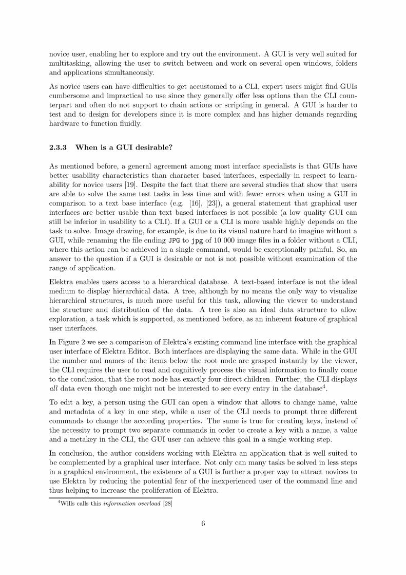
Figure 6 – Proximity: Objects placed near each other appear to be in a group. The viewerwill see three horizontal lines based on the fact, that the dots vertically closer together thanhorizontally.
The law of proximity states that items placed near each other appear to be in a group. Viewerswill mentally organise closer elements into a coherent object, because they assume that closelyspaced elements are related and those further apart are unrelated. In Figure 6 the viewer willsee three rows instead of three columns, because the circles are positioned closer horizontallythan vertically.
3.2.5 Similarity
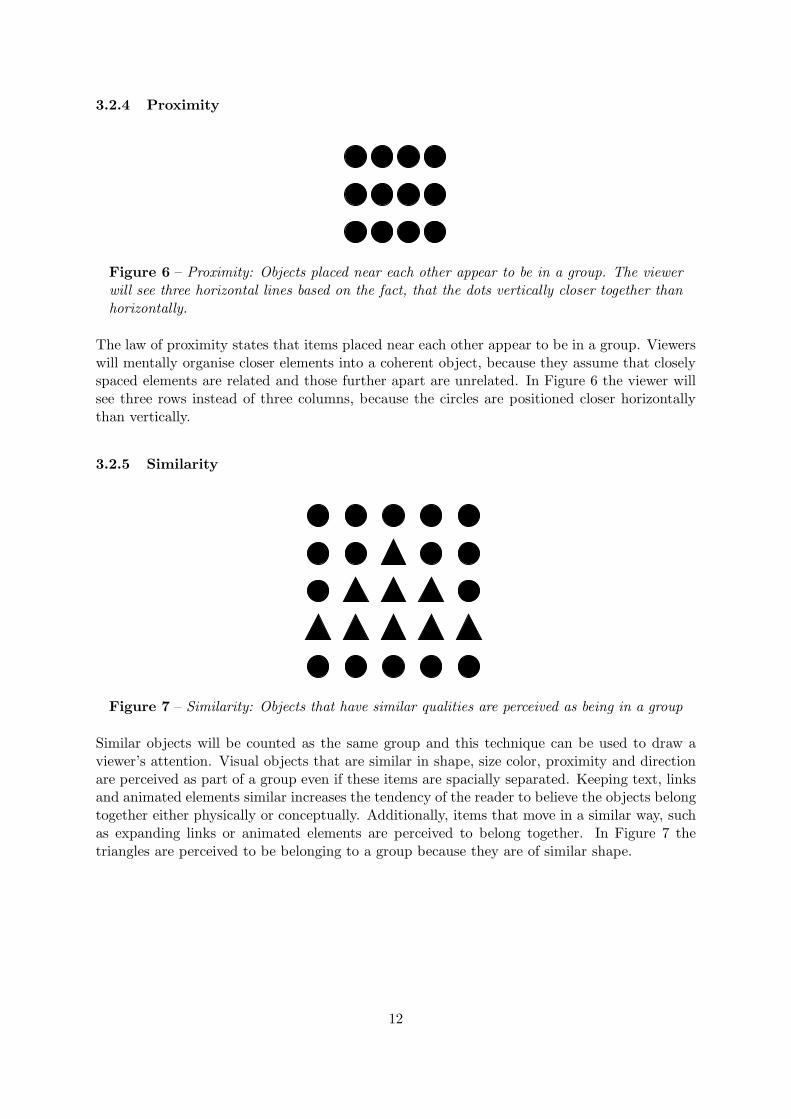
Figure 7 – Similarity: Objects that have similar qualities are perceived as being in a group
Similar objects will be counted as the same group and this technique can be used to draw aviewer’s attention. Visual objects that are similar in shape, size color, proximity and directionare perceived as part of a group even if these items are spacially separated. Keeping text, linksand animated elements similar increases the tendency of the reader to believe the objects belongtogether either physically or conceptually. Additionally, items that move in a similar way, suchas expanding links or animated elements are perceived to belong together. In Figure 7 thetriangles are perceived to be belonging to a group because they are of similar shape.
12

4 Requirements & Use Cases
4.1 Requirements
Requirements stand at the beginning of every software project [24]. They define which problemthe product should solve and which features it should come with. Requirements have thefunction of a contract and help each stakeholder - that is a person who is somehow involvedwith a project - to reach a common understanding of the features of the software. Typicallycustomers have a different sight on a product than developers. Customers often do not knowwhat they want or how things can be realized while developers only have a technical approachto a project and do not know if customers are satisfied.
Stable requirements are very important in the software development process, nevertheless theyoften are subject to change. To adapt to changing requirements agile development methodsare recommended. The agile approach does not follow a strict schedule (like e.g. the WaterfallModel) but is iterating, completing a specified task on each cycle and thus can adapt to changingconditions.
Requirements can be separated in four main groups [25]:
1. Functional Requirements describe required behaviour in terms of required activity,like reactions to input.
2. Nonfunctional Requirements describe quality characteristics of the software, like re-sponse time or ease of use.
3. Design Constraints are technical decisions like the target platform or certain frameworksthat have to be used.
4. Process Constraints describe the methodology of how the system should be build, likean agile approach
Requirements need to be of high quality to actually be helpful to create a successful product.There are eight characteristics requirements should fulfill [25]:
1. Correctness Do the documented requirements conform to the actual understanding ofthe requirements?
2. Consistency Do requirements contradict each other?
3. Unambiguousness Is there no more than one valid interpretation of each requirementfor every reader?
4. Completeness Do the requirement specify the required behaviour for all possible inputsunder all possible constraints?
5. Feasibility Is there a realistic solution for every problem a requirement defines?
6. Relevancy Are all requirements necessary for the product to achieve its goal?
7. Testability Is it possible to tell if a requirement is met or not?
8. Traceability Are the requirements organized and labeled, so that they can be referenced?
The author compiled 19 functional and 5 non-functional requirements, 2 design and 1 processconstraint.
13

There are several possibilities how requirements can be modelled e.g. by Entity-RelationshipDiagrams, class diagrams, state machines or petri nets. The approach in this thesis was tocreate use cases that illustrate the functional requirements. The complete requirements can befound in Appendix B.
4.2 Use Cases
Use cases are a way to specify functional requirements and to document the behaviour of softwaresystems. A use case is a black-box that does not mention anything about implementation orplatform details, but only the system’s reaction to user input. Use cases are text based andwritten in casual language, intended to be easily understandable by human beings.
Alistair Cockburn defines a use case as
a description of the possible sequences of interactions between the system underdiscussion and its external actors, related to a particular goal. [5]
As we see, the definition says that a use case contains a system, actors and some interactionsthat should lead to a goal. The main actor - called primary actor - is the person (or, in somecases, another system) who interacts with the system the use case is describing. The interactionsare called scenario and contain all actions that are needed to allow the primary actor to achievethe goal, but - equally important - also the ones that are not successful in doing so.
Based on the 19 functional requirements, the author created 18 use cases. They are based on atemplate Alistair Cockburn made available on his web site5. The original template containeditems that the author considered unnecessary for the purpose of this project (like Priority orPerformance Target) and created the use cases based on the following elements:
Primary Actor The person that interacts with the system.
Preconditions Certain factors that need to be fulfilled to allow the primary actor to reachthe goal, e.g. there need to be keys present in the database in order to delete them.
Success End Condition A description of the state of the system after the primary actorreached the goal (generally the purpose of the use case, e.g. that the key is in fact removedfrom the database when deleted by the actor).
Failed End Condition Describes the state of the system after the primary actor missedthe goal (e.g. that the key is still present in the database when the user tried to delete thekey).
Main Success Scenario A detailed step-by-step description of the user interacting withthe system that leads to the success end condition, e.g. describing all possibilities the userhas to delete a key.
Extensions Lists all steps of the main scenario that can happen differently, e.g. insteadof successfully creating a new key when pushing the Ok button, an error message pops upthat informs the user that the provided key name is illegal.
Sub-Variations An alternation of a step from the main scenario (e.g. instead of deletinga key by pushing the DEL button on the keyboard, the primary actor instead removes thekey by using the menu).
5http://alistair.cockburn.us/Basic+use+case+template
14
All use cases can be found in Appendix C.
5 Implementation
5.1 Wireframe Model
Alan Cooper tells us in his paper The Perils of Prototyping that “it is easier to break concretethan to change code” [6]. While this statement might or might not be true, it is certainlyadvisable for every programmer to respect the comment’s message: to prototype an applicationbefore beginning to implement it. Following Cooper’s advice, the author created several fullyfeatured wireframe mockup models of Elektra Editor based on the usecases. The interactivemodels were designed with the software Pencil and could be explored by the user. If certainworkflows proved to be unpractical, the design was changed and integrated in the usecases untilthe results were assessed as satisfying. Overall there were four iterations until the model wascompleted.
Figure 8 compares the main view of the final iteration of the model with the main view of thefinished application. The style of the model is deliberately kept simple to signal that it is onlya draft and to allow the viewer to focus on the essential aspects (colors or fancy details couldeasily distract the viewers attention). As we see, the main window of the application looksalmost exactly like the model’s. There are only minor differences like the number and names ofthe menus in the menubar or the design of the meta-area. The finished model was then usedas a template when implementing Elektra Editor.
5.2 Qt
Since Elektra is a C library that offers C++ bindings, the author chose the platform indepen-dent Qt (pronounced cute) framework to implement Elektra Editor. The company behind theframework describes Qt as a
leading cross-platform application and UI development framework for all the majordesktop, embedded and mobile operating systems. Qt uses standard C++ and iswidely used for developing software applications with a GUI and also for developingnon-GUI applications with features such as file handling, database access, XMLparsing, thread management and network support6.
At the moment of this writing, Qt is available in version 5.4.1 and can be downloaded undervarious licenses at the developer’s homepage http://www.qt.io/download/.
Among the most notable features of the framework are the QObject7, which is the base classof all Qt objects, the signal and slot mechanism8 that is used to allow communication betweenQObjects and the meta-object compiler9 moc that translates macros provided by Qt into C++code and hereby extending the language with concepts that do not natively exist in standardC++. To create graphical user interfaces Qt offers three modules: Qt Widgets10 for classic
6https://www.qt.io/about-us/7http://doc.qt.io/qt-5/qobject.html8http://doc.qt.io/qt-5/signalsandslots.html9http://doc.qt.io/qt-5/moc.html#moc
10http://doc.qt.io/qt-5/qtwidgets-index.html
15

(a) Wireframe Model
(b) Elektra Editor
Figure 8 – Comparison Wireframe Model vs. final Application: the main view. On the leftside the user can traverse the hierarchical structure of the configuration. On the right sidethe user can select single keys that are leaves of the tree on the left. On key selection, themetakeys of the selected key appear on the bottom right. On the top right there is a searchbar that allows the user to locate keys based on text input while the top left is the locationof the toolbar buttons.
desktop-style user interfaces, Qt WebKit11 for dynamic web content and Qt Quick12, which isthe newest module and introduces a new declarative language to write GUIs with, Qt ModellingLanguage (QML).
5.3 Qt Quick & QML
Qt Quick and QML were first introduced with the release of Qt 4.7.0 in 2010 [2]. The declarativelanguage QML was created to react to the growing popularity of mobile computing in the
11http://doc.qt.io/qt-5/qtwebkit-index.html12http://doc.qt.io/qt-5/qtquick-index.html
16
last decade that has more and more replaced the classical static desktop environment. Dueto the nature of mobile devices, a strong focus of Qt Quick was on touch based interfaceswhile being compatible to all major desktop and mobile systems. QML is a markup language,designed to quickly create sophisticated user interfaces while being easy to read and write bydevelopers.
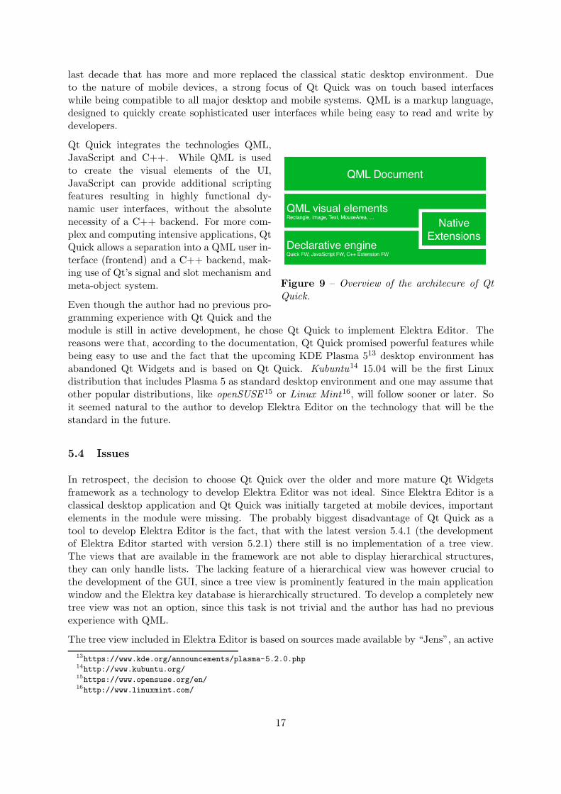
Figure 9 – Overview of the architecure of QtQuick.
Qt Quick integrates the technologies QML,JavaScript and C++. While QML is usedto create the visual elements of the UI,JavaScript can provide additional scriptingfeatures resulting in highly functional dy-namic user interfaces, without the absolutenecessity of a C++ backend. For more com-plex and computing intensive applications, QtQuick allows a separation into a QML user in-terface (frontend) and a C++ backend, mak-ing use of Qt’s signal and slot mechanism andmeta-object system.
Even though the author had no previous pro-gramming experience with Qt Quick and themodule is still in active development, he chose Qt Quick to implement Elektra Editor. Thereasons were that, according to the documentation, Qt Quick promised powerful features whilebeing easy to use and the fact that the upcoming KDE Plasma 513 desktop environment hasabandoned Qt Widgets and is based on Qt Quick. Kubuntu14 15.04 will be the first Linuxdistribution that includes Plasma 5 as standard desktop environment and one may assume thatother popular distributions, like openSUSE 15 or Linux Mint16, will follow sooner or later. Soit seemed natural to the author to develop Elektra Editor on the technology that will be thestandard in the future.
5.4 Issues
In retrospect, the decision to choose Qt Quick over the older and more mature Qt Widgetsframework as a technology to develop Elektra Editor was not ideal. Since Elektra Editor is aclassical desktop application and Qt Quick was initially targeted at mobile devices, importantelements in the module were missing. The probably biggest disadvantage of Qt Quick as atool to develop Elektra Editor is the fact, that with the latest version 5.4.1 (the developmentof Elektra Editor started with version 5.2.1) there still is no implementation of a tree view.The views that are available in the framework are not able to display hierarchical structures,they can only handle lists. The lacking feature of a hierarchical view was however crucial tothe development of the GUI, since a tree view is prominently featured in the main applicationwindow and the Elektra key database is hierarchically structured. To develop a completely newtree view was not an option, since this task is not trivial and the author has had no previousexperience with QML.
The tree view included in Elektra Editor is based on sources made available by “Jens”, an active
13https://www.kde.org/announcements/plasma-5.2.0.php14http://www.kubuntu.org/15https://www.opensuse.org/en/16http://www.linuxmint.com/
17

member of the official Qt forums17. Jens, who seems to be a developer of the Qt framework,contributed the code as reaction to a posting asking for advice to simulate a tree view18. This“hacked” tree view enabled basic functions a developer would expect of a tree view, except, asit turned out, support for keyboard navigation, the possibility to externally extend and collapsetree branches without direct user interaction and a drag and drop functionality.
The tree view Jens posted was only connected to a nested QML ListModel19, a structurenot appropriate for the complex functionality a GUI for Elektra demanded. Due to the factthat Qt Quick only features list views it was not possible to use a QAbstractItemModel20 asC++ backend for the view, as it would have certainly been the case had the application beendeveloped with the Qt Widgets module. The QAbstractItemModel class is specifically designedto manage hierarchical data and assigns each element in the model a unique QModelIndex21.This index allows the programmer to globally reference each item without any ambiguity.
Instead, the backend model for the tree view was created of nested one dimensional QAbstract-ListModels22 that are not intended to be used for hierarchical data. Since a QAbstractList-
Model is derived from a QAbstractItemModel it also assigns a QModelIndex, but this indexis only valid in the specific treebranch and not in the whole tree. In consequence, it requireda lot of additional tweaking to give the model the properties that were required to be usableas a hierarchical tree model and to ensure, that the tree view was properly updated on datachanges.
A possible pitfall of QML that can lead to seemingly mysterious crashes is object ownership.C++ is a language that does not come with a garbage collector, so the programmer has to takecare of every object he created. That means, he has to make sure that each object is properlydestroyed if it is no longer needed. As we have seen earlier, QML is based on JavaScript, alanguage that does come with a garbage collector, so objects that are no longer referenced areautomatically destroyed by the engine. In this context it is important to know, that if a QObjectis returned from an explicit C++ method call QML assumes ownership of the object, unlessthe ownership of the object has explicitly been set to remain with C++23.
In conclusion, the decision to use Qt Quick to implement Elektra Editor complicated andescalated the project. It led to the fact, that the tree view can not be navigated with thekeyboard and that Elektra Editor provides no drag and drop feature. Should Qt Quick includea native treeview in the future, it will be necessary to rewrite the whole C++ backend tointegrate it in the application.
6 Evaluation
6.1 System Usability Scale
To evaluate the usability of the GUI, System Usability Scale (SUS) was chosen. SUS was firstdescribed by Brooke as a “quick and dirty” evaluation method [3]. Brooke stresses that the
17http://qt-project.org/forums/18http://qt-project.org/forums/viewreply/146845/19http://doc.qt.io/qt-5/qml-qtqml-models-listmodel.html20http://doc.qt.io/qt-5/qabstractitemmodel.html21http://doc.qt.io/qt-5/QModelIndex.html22http://doc.qt.io/qt-5/qabstractlistmodel.html23http://doc.qt.io/qt-5/qtqml-cppintegration-data.html
18

usability of a system is a quality that can only be measured by considering its context, purposeand field of application. It would make no sense, so Brooke, to compare the usability of aword processing system with the usability of an industrial process that is meant to producechemicals. The features that qualify a text processor as effective, efficient and satisfactory(ISO 9241-11 definition of usability) as well as its field of use are completely different from asystem that is employed in a chemical plant. Therefore, it is not trivial to compare usabilityacross different systems. SUS was created with the idea to make the comparison of differentapplications possible in spite of the problems described above.
SUS has a number of benefits: it has only ten items (see Table 2), so it is quick to answer andto score, it is non proprietary, so no fees have to be payed to use it and it can be employedon a wide area of applications. The original SUS survey speaks of a system that is underevaluation; by switching the word system to a less abstract expression that better describes theexamined object (like, for example, website or keyboard) it is possible to apply SUS to almostevery application that offers a human interface. In fact, it has been used to evaluate, amongstothers, websites [29], cd players [13], virtual keyboards [15] and safety signs [17].
The result of the survey is a number between 0 and 100. It is important to notice that thisnumber is not expressing a percentage, the score is dimensionless. In order to give this numbera meaning, Bangor et al. [1] tried to map the SUS score to letter grades, common on mostmajor US universities, as well as to adjective ratings and an acceptability range (See Figure10).
Figure 10 – SUS Score Mapping [1]
In a study of the performance of five questionnaires assessing website usability it was foundthat SUS, despite it’s simplicity, “yielded among the most reliable results across sample size”[27]. According to the same study, there are 12 to 14 participants needed to “get reasonablyreliable results”.
There are however also downsides: due to the “quick and dirty” characteristics of the survey,SUS is only able to tell reliably that there are major usability issues with an application, butit is hard to tell, where exactly these problems are and how to address them. SUS is onlysupposed to quickly and reliably determine if major usability issues with a system exist. If theresults of an evaluation indeed suggest that major usability issues are present, there are morespecific examinations required.
6.2 Methodology
The evaluation took place in a single computer laboratory environment located in the ViennaTechnical University. Students of a beginner programming class were invited by E-Mail toparticipate in the evaluation. To increase the attraction of the invitation, the students were
19

Statement English German
S 1 I think that I would like to use thisapplication frequently.
Ich denke, dass ich die Anwendunggerne haufig benutzen wurde.
S 2 I found the application unnecessarilycomplex.
Ich fand die Anwendung unnotig kom-plex.
S 3 I thought the application was easy touse.
Ich fand die Anwendung einfach zu be-nutzen.
S 4 I think that I would need the supportof a technical person to be able to usethis application.
Ich glaube, ich wurde die Hilfe einertechnisch versierten Person benotigen,um die Anwendung benutzen zukonnen.
S 5 I found the various functions in thisapplication were well integrated.
Ich fand, die verschiedenen Funktio-nen in dieser Anwendung waren gutintegriert.
S 6 I thought there was too much incon-sistency in this application.
Ich denke, die Anwendung enthielt zuviele Inkonsistenzen.
S 7 I would imagine that most peoplewould learn to use this applicationvery quickly.
Ich kann mir vorstellen, dass die meis-ten Menschen den Umgang mit dieserAnwendung sehr schnell lernen.
S 8 I found the application very cumber-some to use.
Ich fand die Anwendung sehrumstandlich zu nutzen.
S 9 I felt very confident using the applica-tion.
Ich fuhlte mich bei der Benutzung derAnwendung sehr sicher.
S 10 I needed to learn a lot of things beforeI could get going with this application.
Ich musste eine Menge lernen, bevorich anfangen konnte, die Anwendungzu verwenden.
Table 2 – SUS Questionnaire
promised an extra bonus point on an exam if they would take part in the study. The decision tooffer the bonus point proved to be essential, only one participant was willing to attend withoutany personal benefit.
The study consisted of two parts: participants were supposed to solve tasks with the applicationand then take the SUS questionnaire. To get input besides the evaluation, that, as mentionedin the previous section, can only detect that there are usability problems with the applicationbut cannot tell where these problems are, students were also asked to answer some open ques-tions regarding specific problems they encountered as well as general impressions of the UI. Inorder to know the participants better there also were questions regarding any experience withconfiguration editing software and the GUI development process in general.
Several documents concerning the evaluation existed: an evaluation plan for internal use, thatdescribed the whole planned procedure and formulated the goals that defined whether the resultswould be a failure or success, an instruction sheet handed out to the students that declaredthe purpose of the study and the tasks scheduled to execute and the questionnaire itself (a
20
spreadsheet document) that contained an english and a german version of SUS as well as theother questions that were targeted at the students.
Unfortunately there was an error in the instruction sheet that rooted in the evaluation plan.In the instruction sheet as well as in the evaluation plan it is said, that a grade of 1 meansStrongly Agree and a grade of 5 means Strongly Disagree, when, in fact, it is exactly the otherway around. The same mistake happened on the english version of the questionnaire. Luckilythe german version, which most of the students used, had the correct header, so it is relativelysafe to assume that students were looking at this correct header when grading Elektra Editorand not on the faulty instruction sheet.
6.3 Participants
The participating students where members of a beginner programming class and almost exclu-sively male, which is a typical selection of the Vienna Technical University students of informat-ics. 26 of the 27 participants (approx. 96%) answered the questions that assessed the previousexperience with configuration software and designing graphical user interfaces. 11 of these 26students, or approximately 42%, declared that they had previous experience with configurationmanagement software like Windows Registry, while 13, or exactly 50%, stated that they haddesigned at least one graphical user interface of any kind in the past themselves.
6.4 Goals
The state of the application at the point of the evaluation was nowhere near the supposed finalstate, in fact, it was missing crucial features like undoing/redoing of actions, the possibility toedit search results and it had no keyboard support at all. So the possibilities to create tasksto solve were rather limited and involved locating and editing, deleting and creating keys andmeta-keys, without the option to undo.
Based on Bangor et al. [1] the goals regarding the developed application were set: the abso-lute minimum score to achieve to render the application as success was set to 60. This scorecorresponds to a D on the grade scale and an OK on the adjective scale, while being neitherAcceptable nor Not Acceptable. The minimum preferred score however was set to 71.5 in average,being Good on the adjective ratings, a C on the grade scale and Acceptable on the acceptabilityrange.
6.5 Results
A total of 27 students took the questionnaire. Of these 27 questionnaires eight were not validbecause there were statements either not graded or graded with contradicting scores, like forexample, scoring the same question with 1 as well as 4. Additionally, the remaining validenglish questionnaires were omitted from the evaluation because the header that described themeaning of the scores was incorrect due to a mistake. That left 17 valid questionnaires toevaluate. Details are given in Table 3.
Even though the state of the application at the time of the survey can only be described asunfinished the resulting score was nevertheless above the goals defined before the survey. Theaverage SUS score was 76.47 which is almost 5 points above the preferred score of 71.5 andapproximately 16.5 points above the absolute minimum score of 60. According to the median
21

Participants Total English German
27
7 20
Valid Invalid Valid Invalid
2 5 17 3
Table 3 – SUS Completed Surveys
of 85, 50% of the participants even thought that the application was Excellent on the adjectiverating or a B or better on the grade scale (see Appendix A for complete results).
SUSScore
Participants
0
10
20
30
40
50
60
70
80
90
100
A B C D E F G H I J K L M N O P Q
Figure 11 – SUS Survey Results. The total SUS score for the 17 participants who submitteda completed and valid questionnaire
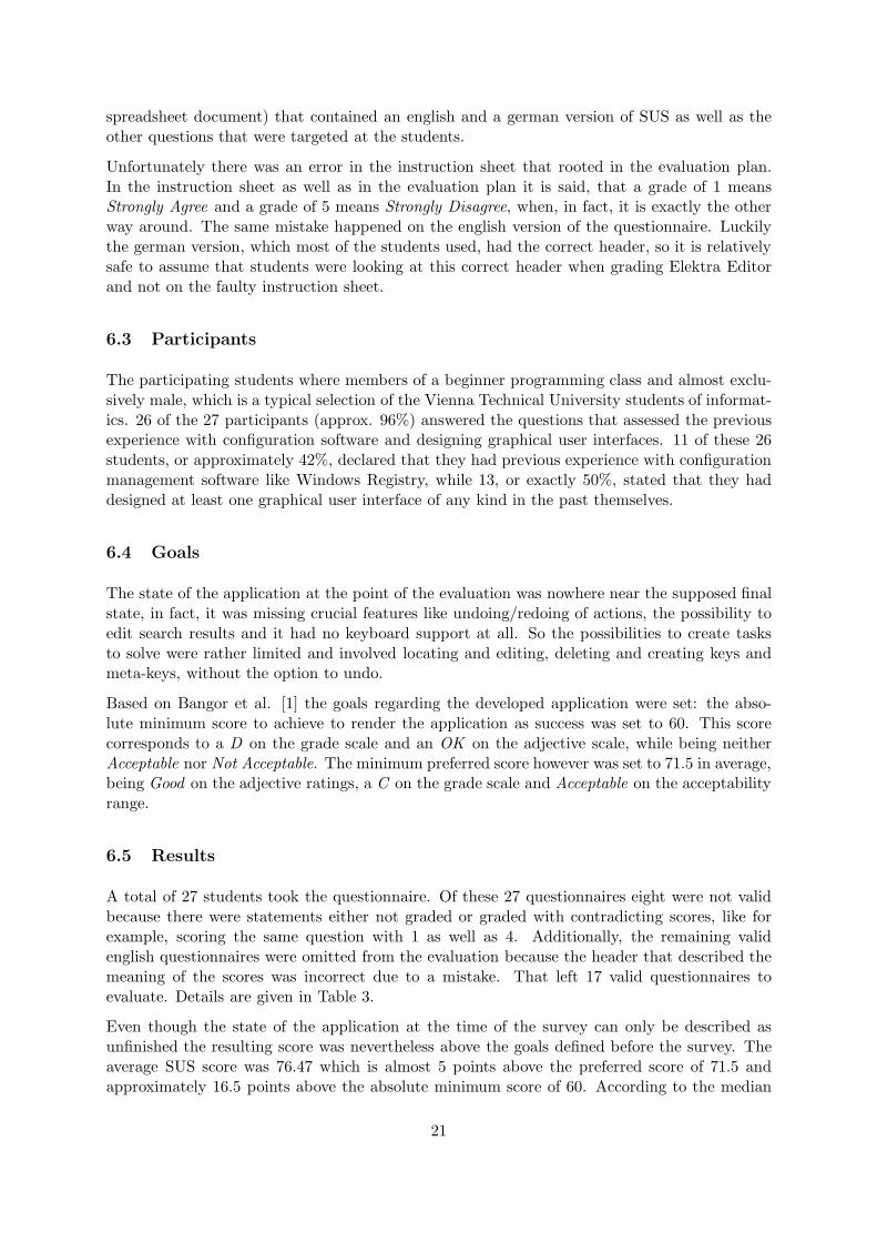
Brooke clearly states that scores for individual items are not meaningful on their own [3]. Withthis limitation in mind it is still interesting to look at the distribution of the grades, as shownin Figure 12.
The most agreement among the participants seems to be on S 4 and S 10 (I think that I wouldneed the support of a technical person to be able to use this application and I needed to learna lot of things before I could get going with this application) where 14 (82%) and 13 (76%)participants strongly disagree with this statement respectively (average 1.53 and 1.65, median 1on both statements). These scores may indicate that the application is well usable for beginnersand first time users, which are among the relevant target group
S 5 caused the most diversity (I found the various functions in this application were well in-tegrated), scoring 3.53 in average and 4 in median, with the highest standard deviation of allstatements. The score and the high deviation might be caused by the unfinished state theapplication was in at the time of the evaluation, still lacking important features.
22
Grade
Statement
1
2
3
4
5
b Outliersrs Pos. phrasedrs Neg. phrased
S 1
b
b
S 2
b
S 3
b
b
b
S 4 S 5
b
S 6
b
S 7
b
S 8
bb
S 9
b
b
bb
S 10
Figure 12 – SUS Distribution. Note that statements 1, 3, 5, 7 and 9 are positive phrasedwhile 2, 4, 6, 8 and 10 are negative phrased in order to avoid response bias by forcingthe respondent to actually read the statement. The ends of the boxes lie at the quartilesQ1 and Q3 and the horizontal line is the statistical median. The whiskers are lines to thefarthest points that are no outliers. An outlier is a point that lies more than 3/2 times theinterquartile range from the end of a box.
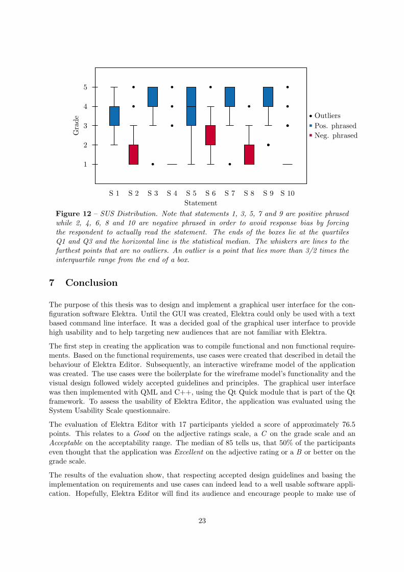
7 Conclusion
The purpose of this thesis was to design and implement a graphical user interface for the con-figuration software Elektra. Until the GUI was created, Elektra could only be used with a textbased command line interface. It was a decided goal of the graphical user interface to providehigh usability and to help targeting new audiences that are not familiar with Elektra.
The first step in creating the application was to compile functional and non functional require-ments. Based on the functional requirements, use cases were created that described in detail thebehaviour of Elektra Editor. Subsequently, an interactive wireframe model of the applicationwas created. The use cases were the boilerplate for the wireframe model’s functionality and thevisual design followed widely accepted guidelines and principles. The graphical user interfacewas then implemented with QML and C++, using the Qt Quick module that is part of the Qtframework. To assess the usability of Elektra Editor, the application was evaluated using theSystem Usability Scale questionnaire.
The evaluation of Elektra Editor with 17 participants yielded a score of approximately 76.5points. This relates to a Good on the adjective ratings scale, a C on the grade scale and anAcceptable on the acceptability range. The median of 85 tells us, that 50% of the participantseven thought that the application was Excellent on the adjective rating or a B or better on thegrade scale.
The results of the evaluation show, that respecting accepted design guidelines and basing theimplementation on requirements and use cases can indeed lead to a well usable software appli-cation. Hopefully, Elektra Editor will find its audience and encourage people to make use of
23

the powerful Elektra library.
While the results of the SUS survey were certainly solid, it must be mentioned again thatElektra Editor was not finished at the time of the evaluation. In fact, important featuresrelevant to usability were missing, like the undo functionality and keyboard support. Whilethe author cannot think of any obvious reason why the SUS score should have been lower,had these features been implemented, stating that the score would have been the same or evenhigher is speculation and could only be told by re-evaluating the application. Since a secondSUS experiment is not scheduled as part of this thesis, the actual System Usability Scale scoreof the final version of Elektra Editor remains unknown.
7.1 Further Work
The main issue that needs to be addressed in Elektra Editor in the future is certainly to switchthe tree view in the frontend with a proper implemented native tree view, should one be availableas part of Qt Quick in one of the upcoming releases. Unfortunately this means, that the C++backend needs to be radically modified as well. At the moment, the backend is based on nestedQAbstractListViews that are not intended to be used as hierarchical data structures. To makeuse of a proper tree view, the model needs to be changed to a QAbstractItemModel. There arecertainly parts and classes of the current code that could be reused in a new implementation, andthis is also true of course for most of the QML frontenend. However, to integrate a new tree viewwould basically mean to completely rewrite the C++ backend and change the communicationof frontend and backend accordingly. The benefits of these changes would be proper keyboardnavigation support, less memory consumption (as there would exist just one model instead ofmany), the possibility to globally reference items, the possibility to implement a drag and dropfunctionality and (presumably) less need to manually ensure that the view properly reflects thechanges in the model, as it is the case at the moment.
24
References
[1] Aaron Bangor, Philip Kortum, and James Miller. “Determining what individual SUSscores mean: Adding an adjective rating scale”. In: Journal of usability studies 4.3 (2009),pp. 114–123.
[2] Jurgen Bocklage-Ryannel and Johan Thelin. Qt5 Cadaques. 2014. url: http://qmlbook.org/.
[3] John Brooke. “SUS-A quick and dirty usability scale”. In: Usability evaluation in industry189 (1996), p. 194.
[4] Dempsey Chang, Laurence Dooley, and Juhani E. Tuovinen. “Gestalt Theory in VisualScreen Design: A New Look at an Old Subject”. In: Proceedings of the Seventh World Con-ference on Computers in Education Conference on Computers in Education: AustralianTopics - Volume 8. CRPIT ’02. Copenhagen, Denmark: Australian Computer Society,Inc., 2002, pp. 5–12. isbn: 0-909925-86-0.
[5] Alistair Cockburn. Writing Effective Use Cases. 1st. Boston, MA, USA: Addison-WesleyLongman Publishing Co., Inc., 2000. isbn: 0201702258.
[6] Alan Cooper. “The perils of prototyping”. In: Visual Basic Programmers Journal (1994).
[7] Design apps for the Windows desktop. 2014. url: http://msdn.microsoft.com/en-us/library/windows/desktop/Aa511258.aspx.
[8] Alan J. Dix et al. Human-Computer Interaction. 2nd. Prentice Hall, 1998. isbn: 0-13-239864-8.
[9] Wilbert O Galitz. The essential guide to user interface design: an introduction to GUIdesign principles and techniques. John Wiley & Sons, 2007.
[10] GNOME Human Interface Guidelines. 2014. url: https://developer.gnome.org/hig-book/stable/.
[11] Kim Goodwin. Designing for the digital age: How to create human-centered products andservices. John Wiley & Sons, 2011. url: http://books.google.at/books?hl=en&lr=&id=yH6Aqr5zKJEC&oi=fnd&pg=PR23&dq=Designing+for+the+Digital+Age+goodwin&
ots=IGFEb1Kklg&sig=WlnnFamF-K-6cbisSqOb2lZbbzY;http://iat.ubalt.edu/cours
es/idia612.085_Fa10/Goodwin_chapter12.pdf.
[12] Lisa Graham. “Gestalt theory in interactive media design”. In: Journal of Humanities &Social Sciences 2.s1 (2008).
[13] Bram Hendriks and Jun Hu. “Redesigning a cd player for intuitive rich interaction”. In:12th International Conference on Human-Computer Interaction, CD Proceddings, Heidel-berg. 2007, pp. 1607–1611.
[14] KDE Human Interface Guidelines. 2014. url: http://techbase.kde.org/Projects/Usability/HIG.
25
[15] Thomas Koltringer and Thomas Grechenig. “Comparing the Immediate Usability of Graf-fiti 2 and Virtual Keyboard”. In: CHI ’04 Extended Abstracts on Human Factors inComputing Systems. CHI EA ’04. Vienna, Austria: ACM, 2004, pp. 1175–1178. isbn:1-58113-703-6. doi: 10.1145/985921.986017.
[16] Sepeedeh Margono and Ben Shneiderman. “A study of file manipulation by novices usingcommands vs, direct manipulation”. In: Sparks of Innovation in Human-computer Inter-action (1993), p. 39. url: http://books.google.at/books?hl=en&lr=&id=G0AdPjbIoVUC&oi=fnd&pg=PA39&dq=a+study+of+file+manipulation+by+novices+shneiderman&
ots=msr8_zzdQX&sig=syyMWrl-U4gBbG- JTQYeEsrbaEA;http://drum.lib.umd.edu/
bitstream/1903/354/2/CS-TR-1775.pdf.
[17] Annie WY Ng, Honour WC Lo, and Alan HS Chan. “Measuring the Usability of SafetySigns: A use of system usability scale (SUS)”. In: Proceedings of the International Multi-Conference of Engineers and Computer Scientists. Vol. 2. 2011.
[18] Jakob Nielsen. “10 Usability Heuristics for User Interface Design”. In: Fremont: NielsenNorman Group.[Consult. 20 maio 2014]. Disponıvel na Internet (1995). url: http://courses.ischool.utexas.edu/rbias/2014/Spring/INF385P/files/10%20Usability%20He
uristics%20for%20User%20Interface%20Design.docx.
[19] Jakob Nielsen. Usability Engineering. San Francisco, CA, USA: Morgan Kaufmann Pub-lishers Inc., 1993. isbn: 0125184050.
[20] Donald A. Norman. The Design of Everyday Things. Basic Books, 2002. isbn: 0465067107.
[21] OS X Human Interface Guidelines. 2014. url: https://developer.apple.com/library/mac/documentation/UserExperience/Conceptual/AppleHIGuidelines/Intro/Intro
.html.
[22] Markus Raab. “A Modular Approach to Configuration Storage”. Diploma Thesis. ViennaUniversity of Technology, 2010.
[23] Matthias Rauterberg. “An empirical comparison of menu-selection (CUI) and desktop(GUI) computer programs carried out by beginners and experts”. In: Behaviour & Infor-mation Technology 11.4 (1992), pp. 227–236. url: http://www.tandfonline.com/doi/abs/10.1080/01449299208924341;http://www.idemployee.id.tue.nl/g.w.m.rauterbe
rg/publications/BIT92paper.pdf.
[24] A. Schatten et al. Best Practice Software-Engineering. Spektrum Akademischer Verlag,2010. isbn: 9783827424877.
[25] J.M.A. Shari Lawrence Pfleeger. Software Engineering: Theory and Practice: Fourth Edi-tion. Pearson Education India. isbn: 9788131762301.
[26] Ben Shneiderman and Catherine Plaisant. Designing the User Interface: Strategies for Ef-fective Human-Computer Interaction (4th Edition). Pearson Addison Wesley, 2004. isbn:0321197860.
[27] Thomas S Tullis and Jacqueline N Stetson. “A comparison of questionnaires for assessingwebsite usability”. In: Usability Professional Association Conference. 2004, pp. 1–12.
26

[28] Graham Wills. “Visualizing Hierarchical Data”. English. In: Encyclopedia of DatabaseSystems. Ed. by LING LIU and M.TAMER OZSU. Springer US, 2009, pp. 3425–3432.isbn: 978-0-387-35544-3. doi: 10.1007/978-0-387-39940-9_1380. url: http://dx.doi.org/10.1007/978-0-387-39940-9_1380.
[29] Moshe Zviran, Chanan Glezer, and Itay Avni. “User satisfaction from commercial websites: The effect of design and use”. In: Information & Management 43.2 (2006), pp. 157–178.
27

Appendices
A SUS Survey Complete Results
Participant S 1 S 2 S 3 S 4 S 5 S 6 S 7 S 8 S 9 S 10 SUS Score
A 3 1 5 1 2 2 4 2 3 1 75.0
B 2 4 3 4 3 2 5 3 2 1 52.5
C 3 1 5 1 5 1 5 1 5 3 90.0
D 5 1 5 1 5 4 5 1 5 1 92.5
E 2 3 4 1 3 3 3 1 4 4 60.0
F 2 3 4 3 3 2 3 2 3 3 55.0
G 3 5 1 5 1 5 1 2 2 5 15.0
H 3 1 5 1 4 2 5 2 4 1 85.0
I 4 2 5 1 2 3 5 1 5 1 82.5
J 4 1 5 1 5 2 5 1 4 1 92.5
K 3 1 5 1 5 1 4 1 5 1 92.5
L 3 1 5 1 4 1 5 1 5 1 92.5
M 5 2 5 1 4 2 5 1 4 1 90.0
N 3 1 4 1 5 2 4 3 5 1 82.5
O 3 2 4 1 1 2 4 4 5 1 67.5
P 5 1 4 1 3 2 5 2 4 1 85.0
Q 5 1 4 1 5 3 4 1 5 1 90.0
Average 3.41 1.82 4.29 1.53 3.53 2.29 4.24 1.71 4.12 1.65 76.47
Median 3 1 5 1 4 2 5 1 4 1 85
Maximum 5 5 5 5 5 5 5 4 5 5 92.5
Minimum 2 1 1 1 1 1 1 1 2 1 15
Rmax−min 3 4 4 4 4 4 4 3 3 4 77,5
σ 1,06 1,24 1,05 1,23 1,42 1,05 1,09 0,92 1,05 1,27 20,86
Table 4 – SUS Survey Complete Results
σ = Standard DeviationRmax−min = Range
28

B Requirements
B.1 Functional Requirements
1. The user should be able to copy keys/array entries within the key database
2. The user should be able to move keys/array entries within the key database
3. The user should be able to remove keys/array entries from the key database
4. The user should be able to create new keys. A key has the following elements:
• name
• value
• meta info
5. The user should be able to create new array entries. An array entry has the followingelements:
• value
• meta info
6. The user should be able to display values of an individual key
7. The user should be able to display meta keys of an individual key. A meta key has thefollowing elements:
• name
• value
8. The user should be able to display info about a plugin
9. The user should be able to import keys from the key database
10. The user should be able to export keys from the key database, including sub trees
11. The user should be able to mount backends
12. The user should be able to unmount backends
13. The user should be able to list mounted backends
14. The user should be able to search for a key by providing the key name or key value
15. The user should be able to undo all changes he did since starting the application
16. The user should be able to (re)load all keys
17. The user should be able to save all keys
18. The user should be able to merge keys
19. The user should be able to display help text by hovering over an item
29

B.2 Non-Functional Requirements
1. The application uses colors that do not limit the user experience for people with colorblindness
2. All functions can be accessed with keyboard shortcuts
3. All errors are communicated to the user
4. The application offers an english or german interface
5. The application scores at least 60 points on the SUS-scale
B.3 Design Constraints
1. The application is realized only with C++/Qt5/QML and thus is portable
2. Quality source code should be ensured by using code review
B.4 Process Constraints
1. The design and implementation process is following an iterative approach
30

C Use Cases
C.1 Copy Key/Array Entry
Use Case #1 Copy Key/Array Entry
Preconditions Keys exist in configuration
Success End Condition Key is copied to new location
Failed End Condition Key is not copied to new location
Primary Actor User of Elektra
Main Success Scenario
Step 1 User traverses to parent of target key in tree structure on left part of screen andselects it with left mouse button
Step 2 User selects desired key with left mouse button on right part of screen
Step 3 User clicks right mouse button to display popup options window
Step 4 User selects option “Copy”
Step 5 User traverses to parent of target key location in tree structure on left part ofscreen and selects it with left mouse button
Step 6 User clicks right mouse button to display popup options window
Step 7 User selects option “Paste”
Extensions
–
Sub-Variations
Step 3 User clicks “Edit” in the menubar with the left mouse button to display optionsdialog
Step 3 User pushes buttons ALT+E on the keyboard to display options dialog
Step 3 User pushes buttons STRG+C on keyboard to copy key
Step 6 User clicks “Edit” in the menubar with the left mouse button to display optionsdialog
Step 6 User pushes buttons ALT+E on the keyboard to display options dialog
Step 6 User pushes buttons STRG+V on keyboard to paste key
31

C.2 Move Key/Array Entry
Use Case #2 Move Key/Array Entry
Preconditions Stored keys exist in configuration
Success End Condition Key is moved from one location to another
Failed End Condition Key is still in the old location
Primary Actor User of Elektra
Main Success Scenario
Step 1 User traverses to parent of target key in tree structure on left part of screen andselects it with left mouse button
Step 2 User selects desired key with left mouse button on right part of screen
Step 3 User clicks right mouse button to display popup options window
Step 4 User selects option “Cut”
Step 5 User traverses to parent of the target key location in tree structure on left partof the screen and selects it with left mouse button
Step 6 User clicks right mouse button to display popup options window
Step 7 User selects option “Paste”
Extensions
–
Sub-Variations
Step 3 User clicks “Edit” in the menubar with the left mouse button to display optionsdialog
Step 3 User pushes buttons ALT+E on the keyboard to display options dialog
Step 3 User pushes buttons STRG+X on keyboard to cut key
Step 6 User clicks “Edit” in the menubar with the left mouse button to display optionsdialog
Step 6 User pushes buttons ALT+E on the keyboard to display options dialog
Step 6 User pushes buttons STRG+V on keyboard to paste key
32

C.3 Remove Key/Array Entry
Use Case #3 Remove Key/Array Entry
Preconditions Stored keys exist in configuration
Success End Condition Key is removed from configuration
Failed End Condition Key is still in configuration
Primary Actor User of Elektra
Main Success Scenario
Step 1 User traverses to parent of target key in tree structure on left part of screen andselects it with left mouse button
Step 2 User selects desired key with left mouse button on right part of screen
Step 3 User clicks right mouse button to display popup options window
Step 4 User selects option “Delete”
Extensions
–
Sub-Variations
Step 3 User clicks “Edit” in the menubar with the left mouse button to display optionsdialog
Step 3 User pushes buttons ALT+E on the keyboard to display options dialog
Step 1 - 7 User pushes buttons “Entf” on keyboard to delete key
Step 6 User clicks “Cancel” button aborting the removal process
33
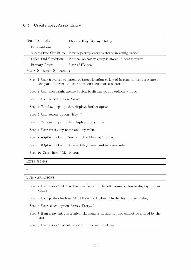
C.4 Create Key/Array Entry
Use Case #4 Create Key/Array Entry
Preconditions -
Success End Condition New key/array entry is stored in configuration
Failed End Condition No new key/array entry is stored in configuration
Primary Actor User of Elektra
Main Success Scenario
Step 1 User traverses to parent of target location of key of interest in tree structure onleft part of screen and selects it with left mouse button
Step 2 User clicks right mouse button to display popup options window
Step 3 User selects option “New”
Step 4 Window pops up that displays further options
Step 5 User selects option “Key...”
Step 6 Window pops up that displays entry mask
Step 7 User enters key name and key value
Step 8 (Optional) User clicks on “New Metakey” button
Step 9 (Optional) User enters metakey name and metakey value
Step 10 User clicks “Ok” button
Extensions
–
Sub-Variations
Step 2 User clicks “Edit” in the menubar with the left mouse button to display optionsdialog
Step 2 User pushes buttons ALT+E on the keyboard to display options dialog
Step 5 User selects option “Array Entry...”
Step 7 If an array entry is created, the name is already set and cannot be altered by theuser
Step 8 User clicks “Cancel” aborting the creation of key
34
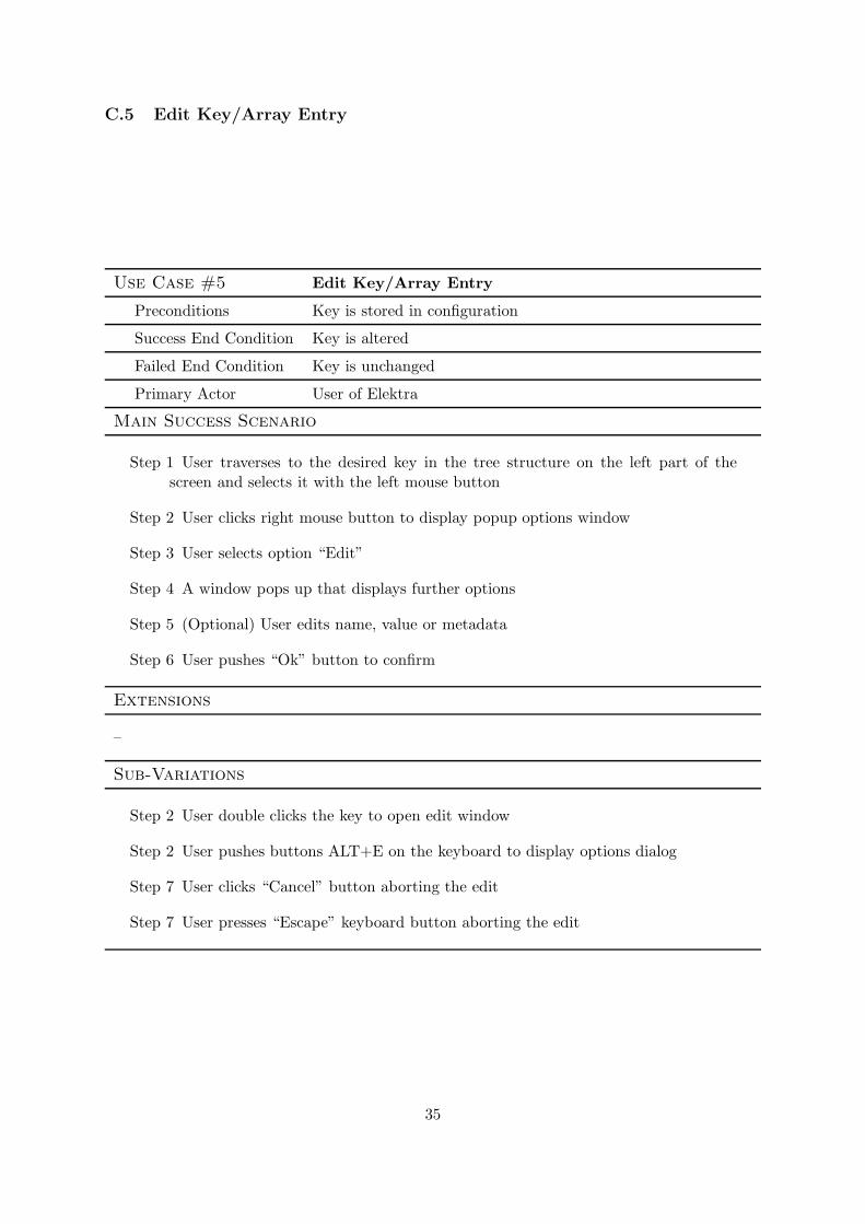
C.5 Edit Key/Array Entry
Use Case #5 Edit Key/Array Entry
Preconditions Key is stored in configuration
Success End Condition Key is altered
Failed End Condition Key is unchanged
Primary Actor User of Elektra
Main Success Scenario
Step 1 User traverses to the desired key in the tree structure on the left part of thescreen and selects it with the left mouse button
Step 2 User clicks right mouse button to display popup options window
Step 3 User selects option “Edit”
Step 4 A window pops up that displays further options
Step 5 (Optional) User edits name, value or metadata
Step 6 User pushes “Ok” button to confirm
Extensions
–
Sub-Variations
Step 2 User double clicks the key to open edit window
Step 2 User pushes buttons ALT+E on the keyboard to display options dialog
Step 7 User clicks “Cancel” button aborting the edit
Step 7 User presses “Escape” keyboard button aborting the edit
35

C.6 Display Value/Metadata of Key/Array Entry
Use Case #6 Display Value/Metadata of Key/Array Entry
Preconditions Keys/array entries are stored in the configuration
Success End Condition Value/metadata of key/array entry is displayed to user
Failed End Condition -
Primary Actor User of Elektra
Main Success Scenario
Step 1 User traverses to parent key of the key of interest in tree structure on left partof screen and selects it with left mouse button
Step 2 Key names and values of keys below the target location are displayed to user
Step 3 User clicks on key of interest
Extensions
–
Sub-Variations
Step 1 User User traverses to key of interest in tree structure on left part of screen
Step 2 User hovers with mouse on a key located in treeview to display value and meta-data
36

C.7 Display Plugin Info
Use Case #7 Display Plugin Info
Preconditions Plugins are available in the configuration
Success End Condition Plugin info is displayed to the user
Failed End Condition -
Primary Actor User of Elektra
Main Success Scenario
Step 1 User selects “Database” in menubar
Step 2 User selects “Show Plugin Info”
Step 3 User selects plugin from dropdown menu
Extensions
–
Sub-Variations
Step 1 User pushed ALT+P button on the keyboard
37
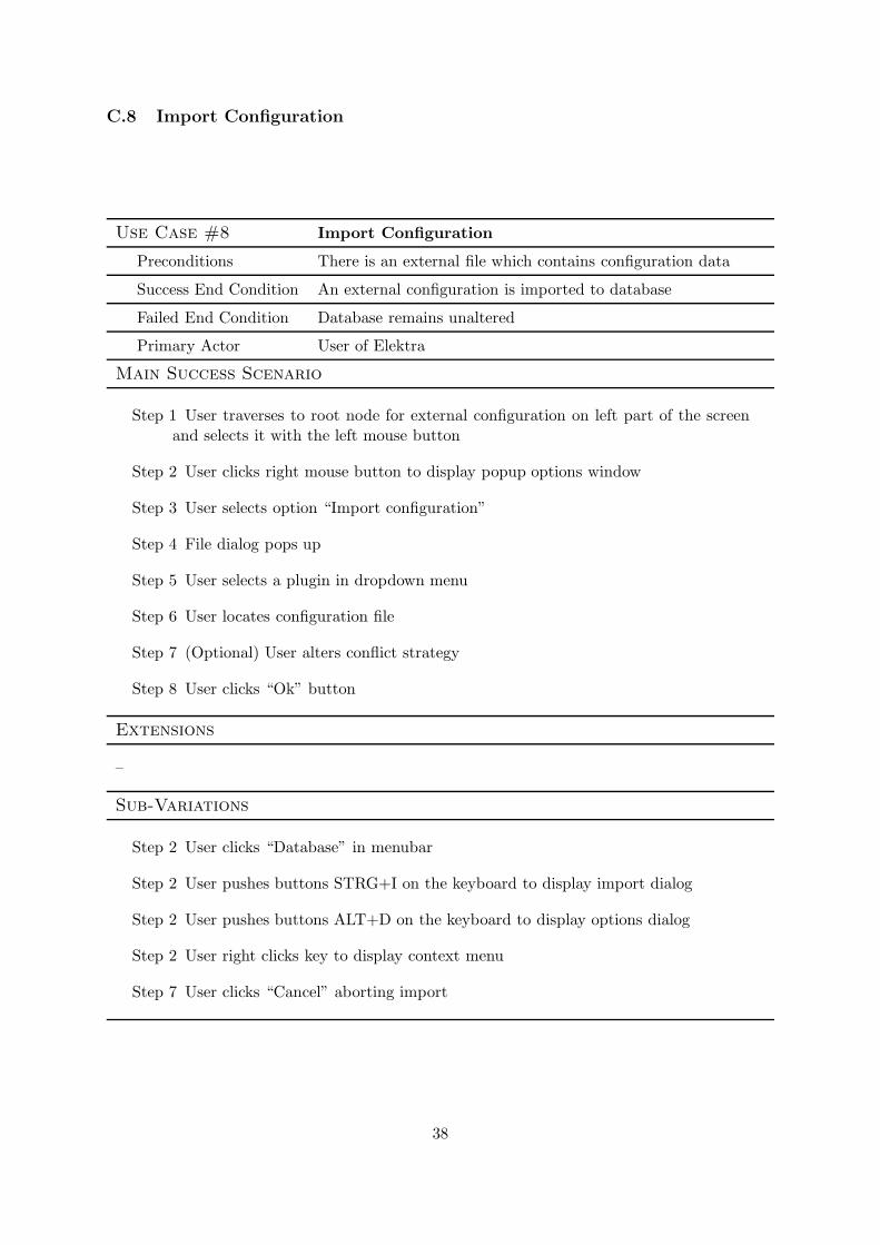
C.8 Import Configuration
Use Case #8 Import Configuration
Preconditions There is an external file which contains configuration data
Success End Condition An external configuration is imported to database
Failed End Condition Database remains unaltered
Primary Actor User of Elektra
Main Success Scenario
Step 1 User traverses to root node for external configuration on left part of the screenand selects it with the left mouse button
Step 2 User clicks right mouse button to display popup options window
Step 3 User selects option “Import configuration”
Step 4 File dialog pops up
Step 5 User selects a plugin in dropdown menu
Step 6 User locates configuration file
Step 7 (Optional) User alters conflict strategy
Step 8 User clicks “Ok” button
Extensions
–
Sub-Variations
Step 2 User clicks “Database” in menubar
Step 2 User pushes buttons STRG+I on the keyboard to display import dialog
Step 2 User pushes buttons ALT+D on the keyboard to display options dialog
Step 2 User right clicks key to display context menu
Step 7 User clicks “Cancel” aborting import
38
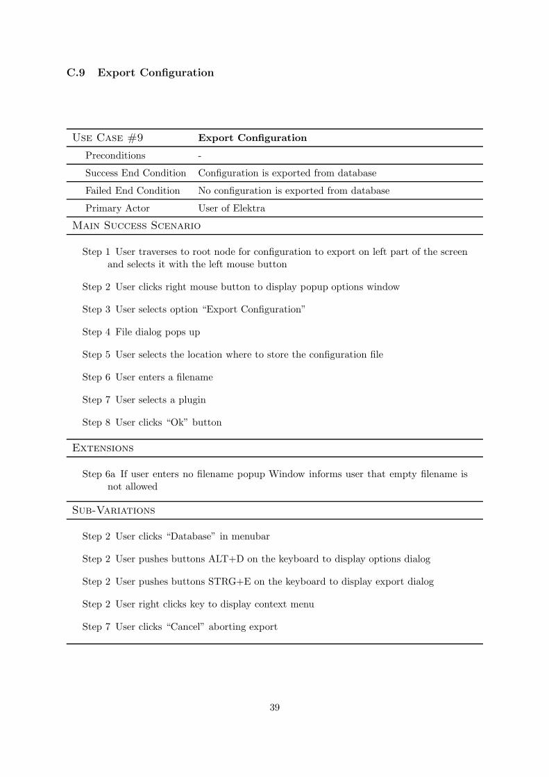
C.9 Export Configuration
Use Case #9 Export Configuration
Preconditions -
Success End Condition Configuration is exported from database
Failed End Condition No configuration is exported from database
Primary Actor User of Elektra
Main Success Scenario
Step 1 User traverses to root node for configuration to export on left part of the screenand selects it with the left mouse button
Step 2 User clicks right mouse button to display popup options window
Step 3 User selects option “Export Configuration”
Step 4 File dialog pops up
Step 5 User selects the location where to store the configuration file
Step 6 User enters a filename
Step 7 User selects a plugin
Step 8 User clicks “Ok” button
Extensions
Step 6a If user enters no filename popup Window informs user that empty filename isnot allowed
Sub-Variations
Step 2 User clicks “Database” in menubar
Step 2 User pushes buttons ALT+D on the keyboard to display options dialog
Step 2 User pushes buttons STRG+E on the keyboard to display export dialog
Step 2 User right clicks key to display context menu
Step 7 User clicks “Cancel” aborting export
39
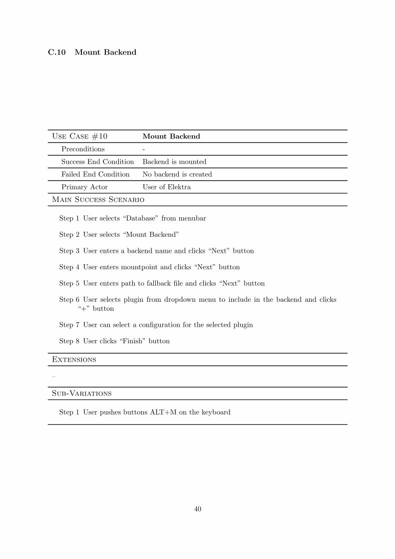
C.10 Mount Backend
Use Case #10 Mount Backend
Preconditions -
Success End Condition Backend is mounted
Failed End Condition No backend is created
Primary Actor User of Elektra
Main Success Scenario
Step 1 User selects “Database” from menubar
Step 2 User selects “Mount Backend”
Step 3 User enters a backend name and clicks “Next” button
Step 4 User enters mountpoint and clicks “Next” button
Step 5 User enters path to fallback file and clicks “Next” button
Step 6 User selects plugin from dropdown menu to include in the backend and clicks“+” button
Step 7 User can select a configuration for the selected plugin
Step 8 User clicks “Finish” button
Extensions
–
Sub-Variations
Step 1 User pushes buttons ALT+M on the keyboard
40

C.11 List/Unmount Backend
Use Case #11 List/Unmount Backend
Preconditions –
Success End Condition Available backends are listed/backend(s) is/are unmounted
Failed End Condition Backend(s) is/are not unmounted
Primary Actor User of Elektra
Main Success Scenario
Step 1 User selects “Database” from menubar
Step 2 User selects “Unmount Backend”
Step 3 List of mounted backends is displayed
Step 4 User selects mountpoint in the list and pushes “Unmount” button
Extensions
–
Sub-Variations
Step 3 If there are no backends available an according message is shown to the user
41

C.12 Find Key
Use Case #12 Find Key
Preconditions -
Success End Condition Desired keys are displayed in the bottom part of the window
Failed End Condition No keys are displayed to the user
Primary Actor User of Elektra
Main Success Scenario
Step 1 User enters search term in search bar
Step 2 User hits “Enter” on the keyboard
Step 3 List of found keys is displayed in the bottom region of the screen. A key will befound if either name, value or any metakey name or metakey value contains thesearch term.
Extensions
–
Sub-Variations
Step 3 If there are no keys in the configuration that match the search terms an accordingmessage is shown to the user
42
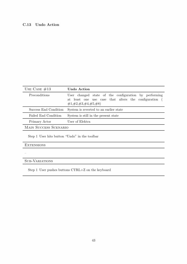
C.13 Undo Action
Use Case #13 Undo Action
Preconditions User changed state of the configuration by performingat least one use case that alters the configuration (#1,#2,#3,#4,#5,#8)
Success End Condition System is reverted to an earlier state
Failed End Condition System is still in the present state
Primary Actor User of Elektra
Main Success Scenario
Step 1 User hits button “Undo” in the toolbar
Extensions
–
Sub-Variations
Step 1 User pushes buttons CTRL+Z on the keyboard
43

C.14 Undo All Action
Use Case #14 Undo All Action
Preconditions User changed state of the configuration by performingat least two use cases that alter the configuration (#1,#2,#3,#4,#5,#8)
Success End Condition System is reverted to the state of the last “Synchronize” action
Failed End Condition System is still in the present state
Primary Actor User of Elektra
Main Success Scenario
Step 1 User hits button “Undo All” in the toolbar
Extensions
–
Sub-Variations
Step 1 User hits button “Undo All” in the toolbar
44

C.15 Synchronize Configuration
Use Case #15 Synchronize Configuration
Preconditions -
Success End Condition Configuration is stored permanently in database
Failed End Condition Configuration is not stored permanently
Primary Actor User of Elektra
Main Success Scenario
Step 1 User clicks “Database” in the menubar with the left mouse button to displayoptions dialog
Step 2 User clicks option “Synchronize”
Extensions
–
Sub-Variations
Step 1 User pushes F5
Step 1 User hits button “Synchronize” in the toolbar
45
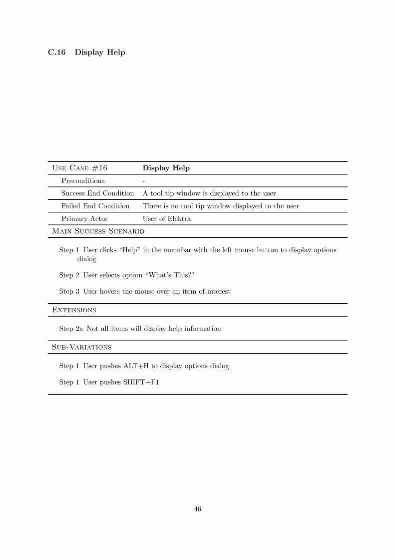
C.16 Display Help
Use Case #16 Display Help
Preconditions -
Success End Condition A tool tip window is displayed to the user
Failed End Condition There is no tool tip window displayed to the user
Primary Actor User of Elektra
Main Success Scenario
Step 1 User clicks “Help” in the menubar with the left mouse button to display optionsdialog
Step 2 User selects option “What’s This?”
Step 3 User hovers the mouse over an item of interest
Extensions
Step 2a Not all items will display help information
Sub-Variations
Step 1 User pushes ALT+H to display options dialog
Step 1 User pushes SHIFT+F1
46

C.17 Quit Application
Use Case #17 Quit Application
Preconditions Application is opened
Success End Condition Application is closed
Failed End Condition Application is opened
Primary Actor User of Elektra
Main Success Scenario
Step 1 User closes application by clicking on close button
Step 2 (Optional) If configuration is in an altered and unsaved state, a dialog pops upthat requires the user to choose between saving or discarding the changes
Extensions
–
Sub-Variations
Step 1 User clicks “Database” in the menubar with the left mouse button to displayoptions dialog
Step 2 User selects “Exit”
47