Design and function of CVC rolls as a flatness actuator in ...525175/FULLTEXT01.pdf · CVC rolls as...
40
Design and function of CVC rolls as a flatness actuator in a cold rolling mill Design och funktion av CVC-valsar som planhetsställdon i ett kallvalsverk Jonas Johannesson 12-02-24 Examensarbete Bearbetningsteknik KTH/MSE--12/08-- SE+CER/EX
Transcript of Design and function of CVC rolls as a flatness actuator in ...525175/FULLTEXT01.pdf · CVC rolls as...

Design and function of CVC rolls as a flatness actuator in a cold rolling mill Design och funktion av CVC-valsar som planhetsställdon i ett kallvalsverk
Jonas Johannesson 12-02-24
Examensarbete Bearbetningsteknik KTH/MSE--12/08--SE+CER/EX


DEGREE PROJECT
Metals working engineering
Programme Reg number Extent
Materials design and engineering, 270 ECTS KTH/MSE--12/08--SE+CER/EX 30 ECTS Name of student Year-Month-Day
Jonas Johannesson 2012-02-24 Supervisor Examiner
Göran Engberg Bill Bergman Company Supervisor at the Company
AB Sandvik Materials Technology Fredrik Sandberg Title
Design and function of CVC rolls as a flatness actuator in a cold rolling mill
Keywords
Flatness, actuators, CVC, cluster mill, cold rolling, strip
Summary
When cold rolling thin steel strips with high tensile strength, reversible cluster mills are used.
The customer’s demands are high on the products flatness, which is controlled by the
different flatness actuators that the mill is equipped with. The objective of this thesis was to
find an optimal CVC shape on the shifting inner second intermediate roll in the 20-high
cluster mill KV96 at Sandvik Materials Technology in Sandviken. The project consisted of a
theoretical calculation of the roll shape that can give the desired change of the strips flatness
and practical development and testing of these rolls in the mill.
The results showed that the flatness of the strips can be altered with up to 30 I-units at the
edges and 20 I-units in the center with the use of an inner second intermediate roll of the CVC
type as this study has concluded.
In this work, three CVC shapes was developed using the calculation software Cluster. The
rolls was then ground and verified in the mill.


EXAMENSARBETE, D-nivå
Bearbetningsteknik
Program Reg nr Omfattning
Materialdesign, 270 hp KTH/MSE--12/08--SE+CER/EX 30 hp Namn Datum
Jonas Johannesson 2012-02-24 Handledare Examinator
Göran Engberg Bill Bergman
Företag Kontaktperson vid företaget
AB Sandvik Materials Technology Fredrik Sandberg
Titel
Design och funktion av CVC-valsar som planhetsställdon i ett kallvalsverk
Nyckelord
Planhet, ställdon, CVC, mångvalsarsverk, kallvalsning, band
Sammanfattning
Vid kallvalsning av tunna band med hög hållfasthet används reversibla mångvalsarsverk.
Kundkraven är höga på produkternas planhet, vilken styrs av de planhetsställdon verket är
utrustat med. Målsättningen med detta examensarbete var att finna en optimal CVC-form på
den förskjutningsbara inre mellanvalsen i 20-valsarsverket KV96 vid Sandvik Materials
Technology AB i Sandviken. Projektet har bestått av att teoretiskt beräkna den valsform som
kan ge den önskade förändringen i planhetsmätarbilden samt att praktiskt ta fram och prova
dessa valsar i verket.
Resultaten visar att man kan påverka planheten på banden med upp till 30 I-enheter i kanten
och 20 I-enheter i mitten med användandet av en inre mellanvals av CVC-typ som denna
studie kommit fram till.
I det här arbetet utvecklades, med hjälp av beräkningsprogrammet Cluster, tre CVC-
valsgeometrier som sedan slipades fram och verifierades i valsverket.


Preface This Master Thesis is the concluding part of the M.Sc. Material Science and Engineering
education at Dalarna University in Borlänge, Sweden.
The work was performed at Sandvik Materials Technology in Sandviken, Sweden, during 20
weeks in the autumn and winter of 2011/2012. Supervisor from Sandvik was Fredrik
Sandberg and from Högskolan Dalarna Göran Engberg.
I would like to thank all persons who have provided help during this thesis work. A special
thank goes however to Lars Carlborg, Fredrik Sandberg, Lars Wikström and the mill
operators for valuable discussions.
Sandviken, February 24th
2012.
Jonas Johannesson


Table of content
1. Introduction .......................................................................................................................... 1
1.1 Background ...................................................................................................................... 1
1.2 Objective .......................................................................................................................... 1
1.3 Workflow ......................................................................................................................... 1
1.4 Boundaries ........................................................................................................................ 1
2. Process description ............................................................................................................... 2
2.1 KV96 ................................................................................................................................ 2
2.2 Process flow ..................................................................................................................... 4
3. Theory ................................................................................................................................... 5
3.1. Rolling ............................................................................................................................. 5
3.1.1 Hot rolling ................................................................................................................. 5
3.1.2 Cold rolling ............................................................................................................... 6
3.2 Flatness ............................................................................................................................. 6
3.2.1 Flatness errors ........................................................................................................... 7
3.2.2 Flatness measuring roll .............................................................................................. 8
3.2.3 Residual stresses ........................................................................................................ 8
3.3 CVC Rolls ........................................................................................................................ 9
3.3.1 Function of CVC rolls ............................................................................................... 9
3.3.2 Variants to CVC ...................................................................................................... 10
3.4 Other flatness actuators .................................................................................................. 10
3.5 Cluster ............................................................................................................................ 13
4. Trials and results ................................................................................................................ 16
4.1 Step tests ......................................................................................................................... 16
4.2 Calculations in Cluster ................................................................................................... 17
4.3 CVC grinding trials ........................................................................................................ 18
4.3.1 Trial one – CVC with diameter difference of 0.22 mm .......................................... 19
4.3.2 Trial two – CVC with diameter difference of 0.35 mm .......................................... 20
4.3.3 Trial three – CVC with diameter difference of 0.47 mm ........................................ 22
5. Discussion ............................................................................................................................ 24
6. Conclusions ......................................................................................................................... 25
7. Proposals for future work .................................................................................................. 26
References ............................................................................................................................... 27
Appendix ................................................................................................................................. 28


1
1. Introduction
During cold rolling of thin strips at Sandvik Materials Technology, 20-high cluster mills are
used to satisfy the strict requirements on flatness- and thickness tolerances that exist. This
project addresses one of these 20-high mills, KV96, that uses no other flatness actuators than
tapered first intermediate rolls and tilting of the upper mill housing.
1.1 Background This cold rolling mill, KV96, are mostly used for rolling thin (<1 mm) martensitic chromium-
steels.
As the name suggests, this mill was built in 1996 by Sundwig and has three main built-in
flatness actuators: Tilting of the upper cluster of rolls, shifting of the tapered first intermediate
rolls and the shifting of the inner second intermediate roll that is supposed to be in a CVC
(Continuous Variable Crown) shape. Some attempts to grind this inner second intermediate
roll into CVC shape has been done but without success or documentary.
1.2 Objective The aim with this thesis was to find the optimal shape on the inner second intermediate roll
and in combination with the tapered first intermediate rolls and tilting be able to improve the
flatness of the strips.
1.3 Workflow Literature study of flatness actuators and rolls of CVC-type.
Theoretical attempts with help of a simulation program from Swerea Mefos, Cluster.
Trials with different CVC shapes on the inner second intermediate rolls.
Evaluation of the grindings both with respect to rolling wear on this roll and adjacent
rolls and of course the flatness of the strip.
FEM (Finite Element Analysis) of the process. Primarily to discover locally high
pressures on the CVC roll.
1.4 Boundaries The main aim was to evaluate whether the flatness can be affected with a CVC-shaped roll as
the inner second intermediate rolls or not. No work has been done on the shape on the tapered
first intermediate roll. Also incoming crown off the strip are of great importance when it
comes to retrieve a good flatness after cold rolling. Neither this has been taken into
consideration of any significance.
2
2. Process description
The following headings explain the process route of the martensitic chromium steel’s product
account and the cold rolling process in KV96.
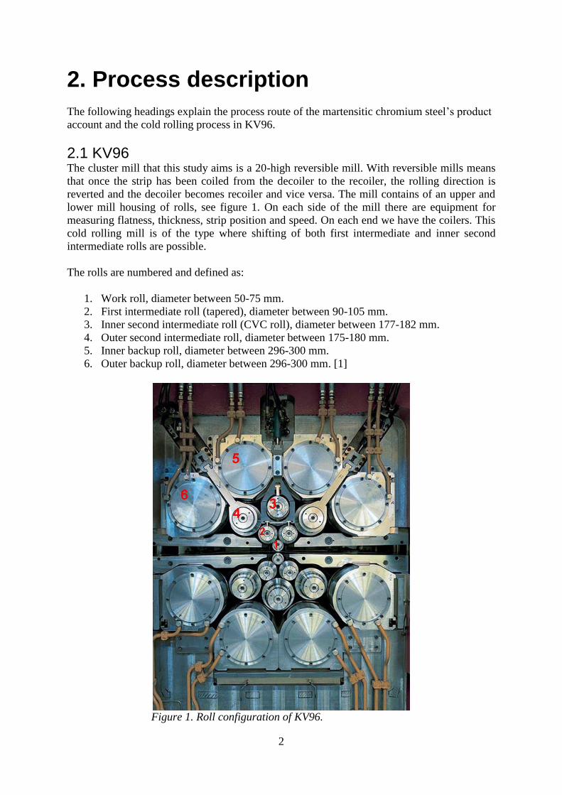
2.1 KV96 The cluster mill that this study aims is a 20-high reversible mill. With reversible mills means
that once the strip has been coiled from the decoiler to the recoiler, the rolling direction is
reverted and the decoiler becomes recoiler and vice versa. The mill contains of an upper and
lower mill housing of rolls, see figure 1. On each side of the mill there are equipment for
measuring flatness, thickness, strip position and speed. On each end we have the coilers. This
cold rolling mill is of the type where shifting of both first intermediate and inner second
intermediate rolls are possible.
The rolls are numbered and defined as:
1. Work roll, diameter between 50-75 mm.
2. First intermediate roll (tapered), diameter between 90-105 mm.
3. Inner second intermediate roll (CVC roll), diameter between 177-182 mm.
4. Outer second intermediate roll, diameter between 175-180 mm.
5. Inner backup roll, diameter between 296-300 mm.
6. Outer backup roll, diameter between 296-300 mm. [1]
Figure 1. Roll configuration of KV96.

3
In this mill the most common type of rolled material is martensitic chromium steel for razor
blades. Outgoing thickness is around 0.10 mm. When the coil arrives to KV96 it has been hot
rolled, cold rolled, intermediate annealed and in most cases grinded on the surface [2].
Flatness measuring – the flatness measuring roll
On the exit side of the mill the strip is bent over a segmented roll, the flatness measuring roll.
This roll measures the force on each segment and in this way the flatness of the strip can be
decided. Figure 2 shows a principal sketch of a flatness measuring roll.
Figure 2. Schematic sketch of a strip divided into fibers and tensioned over
a flatness measuring roll with its measuring zones dotted in the drawing.
With known tension along the strip and the angle on which the strip encloses the roll, the
force on the roll is calculated. This force results in a pressure between the strip and the
flatness measuring rolls segment and is then translated into a flatness unit, often given as an I-
unit. One I-unit is defined by
(1)
where L is the original length and L is the change in length. If, for example, a strip with long
edges is tensioned over the flatness measuring roll, the stress along the strip on the edges will
be lower. This means that the resulting force on that segment where the edge of the strip are
in contact with the flatness measuring roll also will be lower. In this way, the flatness over the
strip can be recognized as seen in figure 3 [1, 2, 3]

4
Figure 3. Long edge strip over a flatness measuring roll.
2.2 Process flow Before the strip reaches the intermediate rolling at KV96 it has first been hot rolled in the
roughing- and Steckel mill. After the hot process the coil is annealed and pickled before any
cold deformation. The first step in the cold process line is pre-rolling in a tandem mill and
after this the strip is annealed once again until it is time for the intermediate rolling. In
addition, the strips are grinded to remove oxides and other surface defects. The intermediate
rolling is a continuous process and the thickness is reduced for each pass. Finally, there is
another annealing before the finishing rolling. Before the strips are delivered to the customer,
they are slitted lengthwise according to the customer’s desired widths. The buyer then
hardens, grinds and punches the strips to improve the hardness and shape of the edges and to
obtain correct dimensions.
The steel is a martensitic stainless chromium steel for razor blades. These steels have a high
deformation resistance. Therefore these kinds of cluster mills are used for the intermediate
rolling because of the high rolling pressures that are needed. Also, the work rolls diameters
are small of the same reason. If same pressure was to be obtained with thicker work rolls the
rolling forces had to be much higher. An advantage with small roll forces is that very good
thickness tolerances can be attained. [2, 3, 4]
5
3. Theory
A literature study regarding following topics have been conducted via databases like
Metadex, Sandvik’s library, personal conversations and previous degree projects that dealt
with the subject.
3.1. Rolling To directly from molten steel produce steel coils is unusual. The steel must often be
processed, where rolling is a central process. Rolling is when a piece of steel is deformed
between two rotating rolls. The process has two main purposes;
1) to plastically deform and change the shape of the work piece (billet, bloom, slab,
strip…)
2) to change the mechanical properties
3.1.1 Hot rolling
Hot rolling is a type of hot deformation, which means that the deformation takes place when
T≥0.5·Tm (half the melting temperature for the work piece). Hot rolling is typically between
0.6·Tm and 0.8·Tm. In hot rolling recrystallization can occur. The grains in the strip can
recrystallize during deformation and this is referred to as dynamic recrystallization. It can also
occur immediately after the deformation, static recrystallization. In some cases the work piece
has to be recrystallized separately from the hot rolling mill [5, 6].
The hot rolling’s prime task is to reduce the thickness of the material, increasing its length so
the strip can be coiled and to break down the microstructure from the casting. Hot rolling is
thus the part of the process chain where the largest deformation takes place. Before rolling the
slab, bloom or billet has a length of about ten meters and after the final cold rolling the strip,
rod or wire can be several kilometers long.
Hot rolling can be performed in several ways. If rolling come about in only one direction in
several successive pair of rolls it is named continuous. If the rolling direction can be changed
and the work piece passes through the same pair of rolls multiple times it is called a reversible
process.
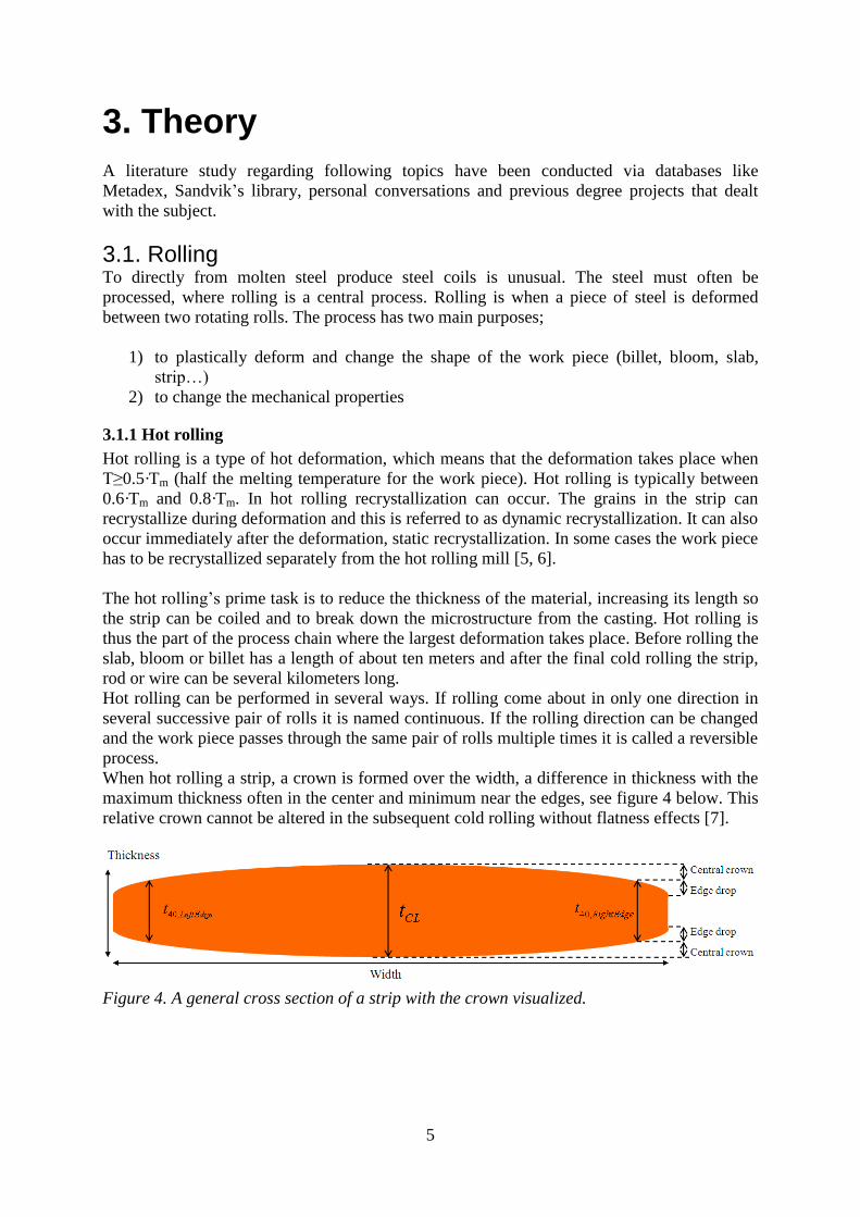
When hot rolling a strip, a crown is formed over the width, a difference in thickness with the
maximum thickness often in the center and minimum near the edges, see figure 4 below. This
relative crown cannot be altered in the subsequent cold rolling without flatness effects [7].
Figure 4. A general cross section of a strip with the crown visualized.

6
The relative crown and wedge are measured a certain distance from the edge due to the edge
drop. In many cases 40 mm from the edge - hence the labeling t-, W- and C40. The crown and
wedge are calculated with the equations [7]:
(2)
(3)
3.1.2 Cold rolling
This type of rolling is processed at room temperature and the material therefore cannot be
recrystallized [5]. Cold rolling is done partly to get the strip thinner, but also to alter the
mechanical properties because the material is deformation hardened during this type of plastic
deformation. The strip will not be wider since transverse flux is almost nonexistent [3]. If the
total reduction is high, annealing between rolling operations may be needed so that the
material is easier to further deform [5].
3.2 Flatness To understand what flatness is, one could imagine a strip divided into fibers and longitudinal
sections (see figure 5). For an absolutely flat strip, these fibers should turn out to be exactly
the same length. Flatness can be described as a comparison between the length difference
between the longest and shortest fiber, see equation 1 [4].
Figure 5. Strip divided into fibers where the outer fibers are longer, long edge strip.
Flatness may also be described by a method that divides the height of the wave with the
wavelength as seen in figure 6 and equation 1 [7].
Figure 6. Waviness of strip with introduced variables for describing flatness in I-units.
Since these differences usually are very small, the values must be multiplied by a factor of 105
to obtain more manageable values.
(1)
L = Current fiber length (when long edge strip, the edge fiber)
L0 = Shortest fiber length (when long edge strip, the center fiber)

7
The flatness is measured in the cold rolling mills as described in section 2.1.
The conclusion is that you want a value as near zero as possible to obtain a flat product.
Depending on the flatness errors after the final rolling and the customer’s specifications
regarding width and flatness, some material may be scrapped. One way to improve the
flatness after rolling is by tension leveling. [4, 5, 6]
3.2.1 Flatness errors
Flatness errors are usually divided into two types – caused by rolling or by coiling. The
coiling related ones are called coil-set and cross bow, see figure 7 [4]. In both cases the error
occurs because of a length difference between the inner and outer surface.
Coil-set is a curvature along the coil where the outer surface becomes slightly longer as the
strip is coiled. This phenomenon is more significant for the first reeled part where the
curvature radius is tighter and/or if the inner diameter is small.
Crossbow can occur if the strip has a crown, described in section 3.1.1. When coiling, this
thickness variation will contribute to that more material is collected where the strip is as its
thickest. This then gives a curvature across the strip. As more material is collected for each
revolution, crossbow will be most evident at the outmost laps [4].
The rolling induced flatness errors can reveal itself as bucklings in the center, well into the
strip (quarter bucklings) or waves at the edges of the strip, see figure 8 [7].
The different cases of rolling induced flatness errors depend on the stress state in the strip. In
cold rolling, one often strives to keep the edges a little longer than the center. This is because
the tension that is applied whilst rolling and a small defect on the edge can lead to a crack
initiation and propagation across the strip and there will be a strip break. If the edges are kept
a little longer, the strip will not be as sensitive to these kinds of defects. Of course this leads
to a flatness error but before final rolling the edges are slitted and hopefully defect free so that
the edges can be kept as long as, or near, the rest of the longitudinal fibers [8].
The crown, which is left from the hot rolling, makes that the fiber(s) that were originally
thicker will now be longer during cold rolling, assumed that the relative reduction is not
constant across the width. This thus also gives a contribution to the flatness deviation [9].
Figure 7. Cross-Bow and Coil Set.
Figure 8. Buckled (long center) and long edge strip respectively.

8
3.2.2 Flatness measuring roll
The flatness is measured by a certain type of segmented roll, which for KV96 is described in
section 2.1. If a strip fiber is shorter than another the pressure will be higher on that zone and
the flatness across the strip can be revealed. Illustrations of three different flatness errors are
illustrated in figure 9 a-c below.
For example, in 9 a) the flatness picture are sketched for a long center strip. It is therefore
tensions at the edges and compressive stresses in the center of the strip.
The flatness measuring roll is both a flatness controlling and a feedback governing unit for the
flatness actuators. [1, 10]
Figure 9 a-c. Long center, quarter buckled and long edge strip respectively and
a schematic sketch of its tension state.
3.2.3 Residual stresses
Residual stresses have a close relationship with the flatness errors. They also arise as a
consequence of the length differences between the projected fibers along the strip. This means
that some fibers would like to adopt an extended form whilst others want to become shorter.
Between these fibers tensions are formed. The difference against the flatness errors is that the
residual stresses are not seen visually. They are also very difficult to measure, although there
are methods for doing so.

9
When the residual stresses are released they can change the shape and properties of the
material, which can make them a major problem later in the production line. A common
example is if a strip is slitted up in narrower parts. These slitted up parts of the mother coil are
different in length and will also have lateral curvature, following as a consequence of released
residual stresses.
Because many customers want to shape and process the strip additionally after the purchase it
is important to maintain control over the residual stresses [4, 6].
3.3 CVC Rolls CVC rolls are most commonly used in hot rolling but in some cases used in cold rolling mills.
The shapes are often of a third-order function or a sinus function (called Smart Crown) [11,
12]. Figure 10 shows a schematic sketch of a CVC roll pair designed with a third-order
function.
Figure 10. A CVC roll pair designed with a third-order function.
3.3.1 Function of CVC rolls
As seen in figures below, shifting of the third-order CVC rolls changes the gap between the
rolls and gives a parabolic effect from a second order function. While shifting the CVC rolls
as for the case in KV96 from -45/+45 to +45/-45 mm, a negative or positive effect can be
obtained.
Figure 11. Shifting of CVC rolls and corresponding parabolic shaped flatness effect.
10
As seen in figure 11, the shifting of the CVC rolls corresponds to an effect of a pure second
order function. This effect can be altered depending on how much the rolls are shifted. If the
rolls are in origin position, there will be no flatness effect at all.
3.3.2 Variants to CVC
Smart Crown is another conventional type of roll shape used in the same way as CVC. The
Smart Crown shape can be described as a sum of sinusoidal and a linear function (Sine
contour, Mathematically Adjusted and Reshaped by Tilting) and gives a cosine-shaped roll
gap contour, whereas it becomes parabolic for CVC rolls [13].
3.4 Other flatness actuators For flatness control and regulation other type of actuators are used in cold rolling mills for
different effects depending on what is desirable.
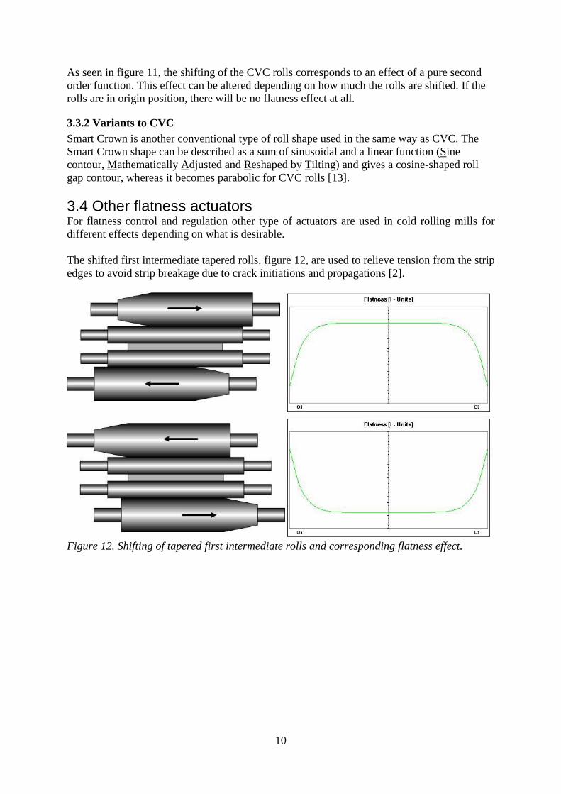
The shifted first intermediate tapered rolls, figure 12, are used to relieve tension from the strip
edges to avoid strip breakage due to crack initiations and propagations [2].
Figure 12. Shifting of tapered first intermediate rolls and corresponding flatness effect.
11
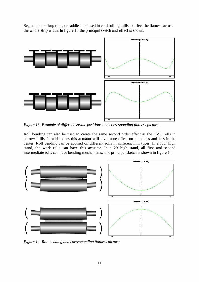
Segmented backup rolls, or saddles, are used in cold rolling mills to affect the flatness across
the whole strip width. In figure 13 the principal sketch and effect is shown.
Figure 13. Example of different saddle positions and corresponding flatness picture.
Roll bending can also be used to create the same second order effect as the CVC rolls in
narrow mills. In wider ones this actuator will give more effect on the edges and less in the
center. Roll bending can be applied on different rolls in different mill types. In a four high
stand, the work rolls can have this actuator. In a 20 high stand, all first and second
intermediate rolls can have bending mechanisms. The principal sketch is shown in figure 14.
Figure 14. Roll bending and corresponding flatness picture.
12
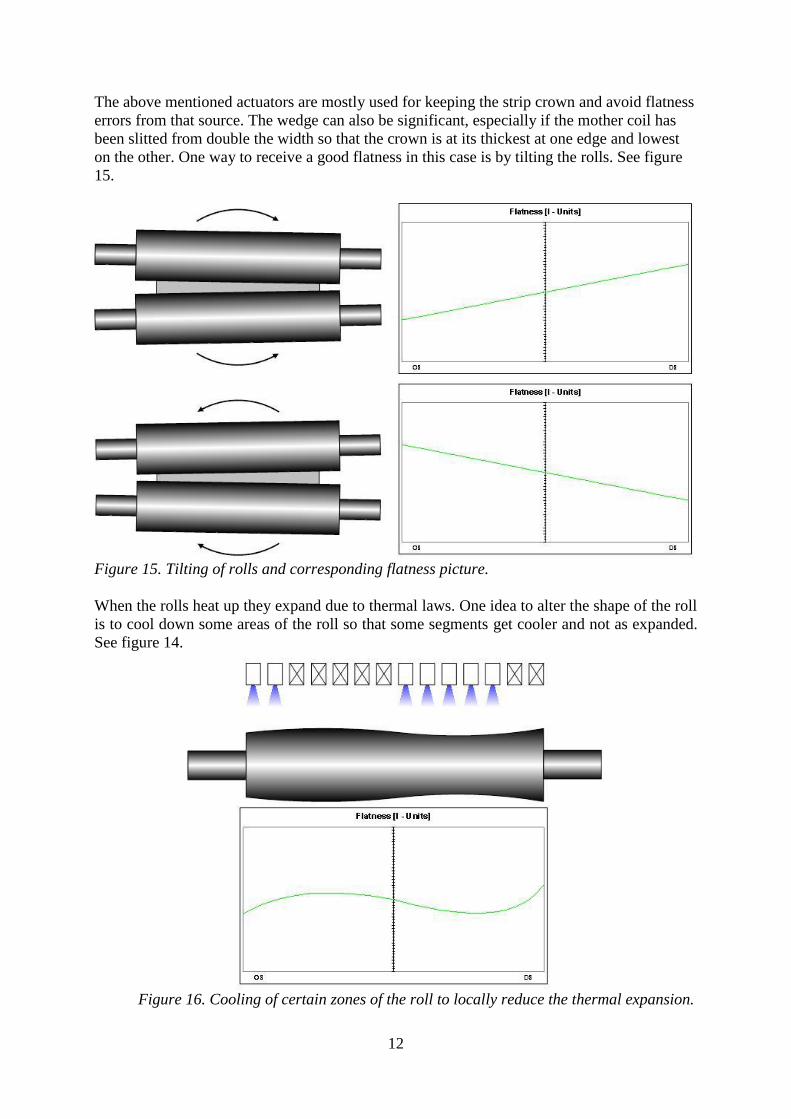
The above mentioned actuators are mostly used for keeping the strip crown and avoid flatness
errors from that source. The wedge can also be significant, especially if the mother coil has
been slitted from double the width so that the crown is at its thickest at one edge and lowest
on the other. One way to receive a good flatness in this case is by tilting the rolls. See figure
15.
Figure 15. Tilting of rolls and corresponding flatness picture.
When the rolls heat up they expand due to thermal laws. One idea to alter the shape of the roll
is to cool down some areas of the roll so that some segments get cooler and not as expanded.
See figure 14.
Figure 16. Cooling of certain zones of the roll to locally reduce the thermal expansion.

13
3.5 Cluster Cluster is a program from Swerea Mefos and is designed for calculations of the profile and
flatness of strips rolled in 20-high cluster mills. Originally this model was derived for a 20-
high mill in Sheffield [14]. Cluster is based on a slab analysis-force method where the both
the mill housing and the strip is segmented across the rolling direction [15]. Furthermore the
model is based on bending and flattening of the roll cluster. Different equations are generated
by geometric compatibility conditions at the interfaces between the various bodies and by
mechanical force equilibrium in both horizontal and vertical direction. These equations are
then solved iteratively.
The assumptions made in the use of the program were as follows [14, 15]:
The mill was symmetrical around the work rolls center line.
Transverse flux of the strip was negligible.
Roll bending due to shear stresses in the rolls were neglected.
So called kiss rolling was ignored. Kiss rolling occurs when thin strips are being rolled
with such high roll pressure and bending moments that the work rolls comes into
contact with each other outside the strip edges.
Four basic calculations are done at execution of the program code [14, 15]:
Calculation of roll bending based on beam theory.
Calculation of roll flattening and pressure distribution between rolls in the cluster.
Calculation of roll flattening and pressure distribution in the roll gap.
Calculation of the outgoing strip profile and residual stress distribution.
The program considers the mills specification such as profiles, diameters, positions and
Young’s modulus of all rolls. Strip material can also be defined with deformation hardening
curve and other material data. Different rolling forces, shifting of rolls and tension can be
defined for each pass [16].
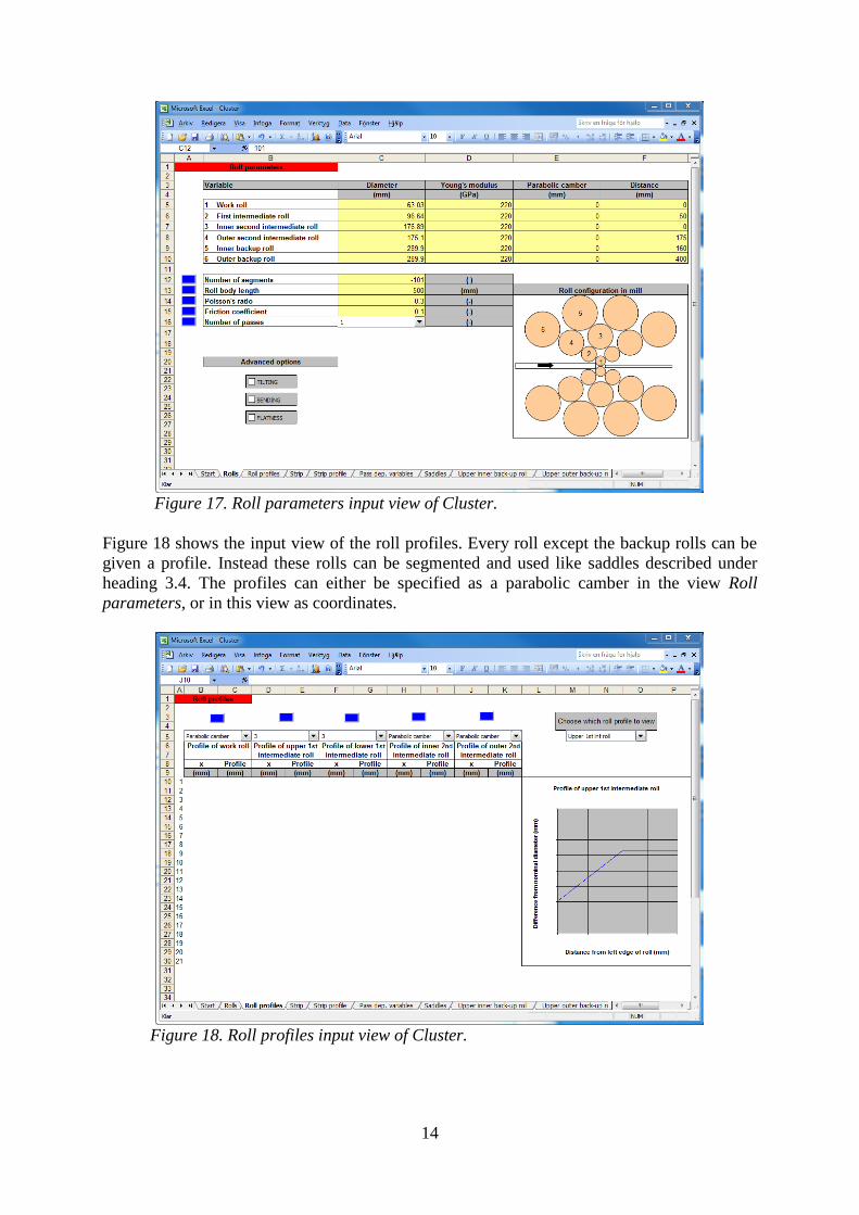
Figure 17 shows the roll parameters input view. Diameter of all rolls, Young’s modulus,
distance from center axis and parabolic camber can be specified. If a parabolic camber is
defined at this stage in mm, the program simply adjusts a second order function and gives the
roll the desired diameter difference from edge to center.
Number of segments inputs the number of calculation segments along the roll. If this value is
specified as a negative number, the calculations are divided in segments across the strip
instead.
Here is an opportunity to also input the number of passes. In this way, the whole rolling
process can be simulated.
14
Figure 17. Roll parameters input view of Cluster.
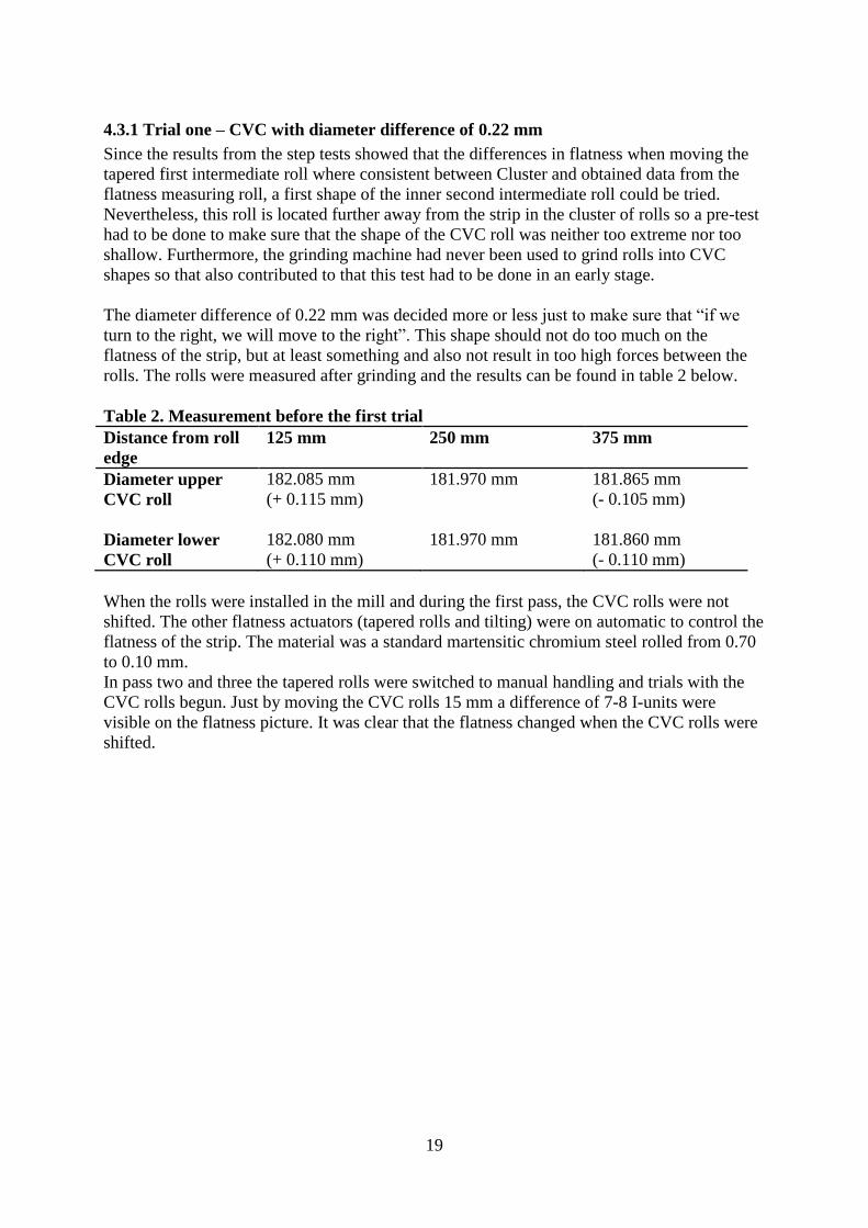
Figure 18 shows the input view of the roll profiles. Every roll except the backup rolls can be
given a profile. Instead these rolls can be segmented and used like saddles described under
heading 3.4. The profiles can either be specified as a parabolic camber in the view Roll
parameters, or in this view as coordinates.
Figure 18. Roll profiles input view of Cluster.

15
Also the strip can be given a certain profile and other parameters. In figure 19 the input view
of the strips parameters are seen. Deformation hardening curve, parabolic crown and other
relevant strip data can be input.
Figure 19. Strip parameters input view.
Cluster was used to predict the flatness change with different type of grindings on the CVC
roll and different shiftings of these. Also the pressure distribution between rolls was of
interest. As will be described in forthcoming heading, Cluster exaggerates the flatness and
residual stress distribution when doing a calculation. The difference between flatness values
from two calculations in which a flatness actuator, for example the CVC roll, are shifted will
give results that represent what you actually expect from the same shifting in KV96.

16
4. Trials and results
The trials and results that follow are divided into the five elements that the project consisted
of:
4.1 Step tests
4.2 Calculations in Cluster
4.3 Trial one – CVC with diameter difference of 0.22 mm
4.4 Trial two – CVC with diameter difference of 0.35 mm
4.5 Trial three – CVC with diameter difference of 0.42 mm
4.1 Step tests To evaluate and ensure Cluster’s ability of accuracy regarding the flatness depending on
corresponding flatness actuator had to be done. Cluster exaggerates the absolute effect of
every flatness actuator but with step tests both in the mill and in Cluster with same conditions
the relation between the program’s results and what the signal from the flatness measuring
roll shows could be done.
The trial setup was to first let every flatness actuator be set on automatic flatness control, then
shut the automatic off and shift the tapered first intermediate rolls in steps and read the
changes in I-units near the edges of what the flatness measuring roll gave.
Same thing was then done in Cluster and the results were consistent, see figure 20.
Figure 20. Changes in I-units with different relative shiftings of first
intermediate tapered rolls.

17
4.2 Calculations in Cluster It was indicated from step test one that the even though Cluster exaggerates the absolute
values of the flatness, the differences in I-units are comparable between Cluster and values
obtained from the step tests at the mill.
When trying to decide the shape of the third order CVC roll profile, or actually the difference
between the local minimum- and maximum points of the roll it was clear that, according to
Cluster, the growth was decreasing. See figure 21 below.
Figure 21. Graph showing declining growth of the flatness difference with more extreme
grindings on the CVC roll.
mm
I-units

18
4.3 CVC grinding trials As mentioned earlier the shape was decided to follow a third order function because of the
desired crowning effect of a second order function. For example, the function that describes a
CVC roll with 1 mm difference between minimum and maximum diameter is:
Where:
And the corresponding graph is shown in figure 22 below.
Figure 22. Principal graph showing the grinding curvature of a CVC roll with 1 mm
difference between minimum and maximum diameter.
The rolls can each be shifted 45 mm. This will give a corresponding crowning effect, see
figure 11, which reaches its maximum when one roll is shifted 45 mm at one side and the
other roll 45 mm at the other direction. These crowning translations are for each and every
trial done is converted in Table 1.
Table 1. Relations between different grindings and corresponding crowning effects
Difference between
minimum and
maximum
diameter
0.22 mm
0.35 mm
0.47 mm
Corresponding
maximum
crowning effect
that can be
obtained per roll
0.08 mm
0.13 mm
0.17 mm
Corresponding
total maximum
crowning effect
that can be
obtained
0.16 mm
0.25 mm
0.34 mm
19
4.3.1 Trial one – CVC with diameter difference of 0.22 mm
Since the results from the step tests showed that the differences in flatness when moving the
tapered first intermediate roll where consistent between Cluster and obtained data from the
flatness measuring roll, a first shape of the inner second intermediate roll could be tried.
Nevertheless, this roll is located further away from the strip in the cluster of rolls so a pre-test
had to be done to make sure that the shape of the CVC roll was neither too extreme nor too
shallow. Furthermore, the grinding machine had never been used to grind rolls into CVC
shapes so that also contributed to that this test had to be done in an early stage.
The diameter difference of 0.22 mm was decided more or less just to make sure that “if we
turn to the right, we will move to the right”. This shape should not do too much on the
flatness of the strip, but at least something and also not result in too high forces between the
rolls. The rolls were measured after grinding and the results can be found in table 2 below.
Table 2. Measurement before the first trial
Distance from roll
edge
125 mm 250 mm 375 mm
Diameter upper
CVC roll
182.085 mm
(+ 0.115 mm)
181.970 mm
181.865 mm
(- 0.105 mm)
Diameter lower
CVC roll
182.080 mm
(+ 0.110 mm)
181.970 mm
181.860 mm
(- 0.110 mm)
When the rolls were installed in the mill and during the first pass, the CVC rolls were not
shifted. The other flatness actuators (tapered rolls and tilting) were on automatic to control the
flatness of the strip. The material was a standard martensitic chromium steel rolled from 0.70
to 0.10 mm.
In pass two and three the tapered rolls were switched to manual handling and trials with the
CVC rolls begun. Just by moving the CVC rolls 15 mm a difference of 7-8 I-units were
visible on the flatness picture. It was clear that the flatness changed when the CVC rolls were
shifted.

20
4.3.2 Trial two – CVC with diameter difference of 0.35 mm
The aim was initially to almost double the previous diameter difference to 0.47 mm and also
be near the area in Figure 21 of what seems most effective. When the rolls were measured
after grinding, the difference between maximum and minimum diameter was only 0.35 mm,
see table 3. The grinding disc used was probably too wide to achieve this diameter difference.
However, the shape itself was fine and these pair of rolls was tried anyway.
Table 3. Measurement before the second trial
Distance from roll
edge
125 mm 250 mm 375 mm
Diameter upper
CVC roll
182.115 mm
(+ 0.170 mm)
181.945 mm
181.765 mm
(- 0.180 mm)
Diameter lower
CVC roll
182.120 mm
(+ 0.175 mm)
181.945 mm
181.770 mm
(- 0.175 mm)
In this trial an austenitic annealed test coil was designated of type EN 4310.
This trial begun in the same way as the previous one, pass one was rolled as usual with the
CVC rolls in origin position and with all other automatic flatness control turned on. In the
following passes the position was altered from +45/-45 to -45/+45 mm and the automatic on
the tapered rolls and tilting were shut off. Results from the flatness measuring roll in pass
three, strip thickness 0.40 mm, showed in figure 23.
Figure 23. Flatness in I-units with different positions of the CVC rolls in step test two. Pass
three, strip thickness 0.40 mm.
Shifting the upper CVC roll +45 (and the lower -45) mm will make a negative parabolic
crowning effect; the center of the strip will be shorter and the edges longer. If the CVC roll is
shifted the other way, -45/+45 mm we will get shorter center and longer edge fibers.
Note that since the strip covers the measuring zones of the flatness measuring roll uneven on
each side, the flatness picture looks a bit warped. However, this is compensated for in the
flatness controlling systems. This phenomenon is seen in both figure 23 and 25 and is only an
esthetical inaccuracy [4].

21
The green line in the figure on the previous page is the flatness state when the CVC rolls are
held in its origin position. The blue and red lines are corresponding flatness measurements
from the most extreme positionings, 45 mm on each roll. The difference between the
blue/green and red/green lines will tell how much the flatness can be affected on each shifting
direction in comparison with no effect. This is illustrated in figure 24 where it is seen that the
total flatness difference at the edges are about 25 I-units and in the center 15 I-units.
Figure 24. Graph showing maximum positive/negative crowning effects obtained from these
CVC rolls used in trial two.
Even though the operators did not use the shifting of the CVC rolls continuously they were
left in the mill for three weeks. When they were changed during an ordinary maintenance
stop, they were measured and the results showed that the profile and shape was exactly the
same as before the trial, see table 3 and Appendix. Also one set of tapered first intermediate
rolls were measured to search for any unusual wear after about one week in the mill together
with these CVC rolls. No wear other than normal was seen [17].

22
4.3.3 Trial three – CVC with diameter difference of 0.47 mm
With a new grinding disc, the diameter difference of 0.47 mm was achieved on the CVC rolls.
See table 4.
Table 4. Measurement before the third trial
Distance from roll
edge
125 mm 250 mm 375 mm
Diameter upper
CVC roll
182.140 mm
(+ 0.240 mm)
181.900 mm
181.670 mm
(- 0.230 mm)
Diameter lower
CVC roll
182.135 mm
(+ 0.235 mm)
181.900
181.665 mm
(- 0.235 mm)
They were tried on the same coil as in trial two; the thickness was now 0.16 mm.
Once again the trial was executed the same way. In pass one, all automatic flatness actuators
was switched on just to tune in the positions of the tapered first intermediate rolls and tilting.
In pass two the tapered rolls and tilting was held at the positions that seemed stable in pass
one and the CVC rolls positions was altered from +45/-45 to -45/+45 mm. Results from the
flatness measurings in pass two, strip thickness 0.16 mm, showed in figure 25 below.
Figure 25. Flatness in I-units with different positions of the CVC rolls in step test three. Pass
two, strip thickness 0.16 mm.
23
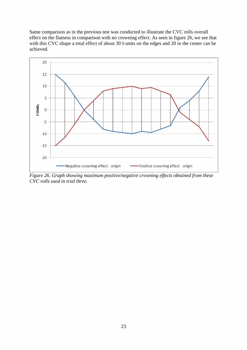
Same comparison as in the previous test was conducted to illustrate the CVC rolls overall
effect on the flatness in comparison with no crowning effect. As seen in figure 26, we see that
with this CVC shape a total effect of about 30 I-units on the edges and 20 in the center can be
achieved.
Figure 26. Graph showing maximum positive/negative crowning effects obtained from these
CVC rolls used in trial three.

24
5. Discussion
Cluster is a powerful and fairly accurate tool for determine the flatness differences between,
for example, two different roll types or grindings. The step tests that has been done indicates
that the difference in results between two type of tests if every other parameter is kept steady
can be of substantial accuracy. Since the software does not consider edge drop, incoming
flatness etcetera one should not rely on the absolute values obtained from Cluster.
From the start there was supposed to be a finite element analysis (FEM) done on the cluster
mill with the CVC roll to see how locally high pressures there can be between the rolls and
also theoretical boundaries of what is possible to bend the first intermediate and tapered rolls.
However, the resolution of the FEM analysis software was not good enough to see any effects
from the relatively small diamteter changes of the CVC roll. The force distribution from
Cluster had to be considered reliable enough. Nevertheless, since the program amplifies the
flatness, it is easy to make the assumption that this data also is corrupt. Of the same reason,
comparisons of force distribution of all tried CVC shapes and cylindrical inner second
intermediate rolls were made. The force distribution was distorted and locally higher when
calculations were made on CVC rolls with greater diameter difference, but only a few percent.
According to the force component drawing from Sundwig the force on the inner second
intermediate roll is only 15 % of the total rolling force. With this in mind and the fact that the
tapered first intermediate rolls absorbs 50 % of the rolling force and that there are theories of
locally grind a convex part on these rolls, the pressures along the CVC roll should not result
in any additional damages of significance on the bearings or the roll itself.
Since the FEM analysis did not provide any results a number of parameters still indicate that
the force and pressure between rolls are manageable:
The results from Cluster.
Nothing out of the ordinary happened in the mill during the weeks when the CVC rolls
were tried.
Since the force on the CVC roll is only about 15 % of the rolling force there should
not be any extreme locally pressures that would jeopardize the durability of the
bearings.
As the CVC-shaped roll has an alternate diameter, whilst rolling the peripheral velocity will
also be different from the parts where the diameter is different. In comparison with forward
slip and also the tapered first intermediate roll that has a higher peripheral velocity and higher
force applied, this effect is ignored.
The designated test coil in trials two and three had a relatively long center compared to a
“normal” strip. Therefore, the assumption that the center can be even shorter on a strip with a
more “normal” incoming flatness can be made.
As seen in figure 24 and 26 the point where the curves meet can be altered with a different
starting point of the third order functions “period”. If the rolls are ground in a way where the
maximums are close to the edges of the roll the effect will be more unsymmetrical in
positive/negative aspect. As they are used in these trials, with a whole “period”, the effect will
be symmetric positive/negative as seen in figure 24 and 26.

25
6. Conclusions
The CVC shapes of the inner second intermediate roll treated in this thesis affects the
flatness of the strips with up to 30 I-units near the edges and 20 I-units in the center.
Since the crowning effect from the CVC roll can be both positive and negative, the
conditions are better for achieving a good flatness on strips with both positive and
negative crown.
Cluster seems to be a good tool for determining the flatness differences between for
example a cylindrical and CVC-shaped inner second intermediate roll.
It seems as more extreme CVC grindings on the inner second intermediate rolls are of
no use. The desired effect is achieved somewhere near 0.47 mm difference between
maximum and minimum diameter according to Cluster. In addition, there will be
harder to grind these shapes without grinding marks.
The shape of the CVC roll can be refined with a Smart Crown profile in order to
optimize the effect further.

26
7. Proposals for future work
During this work additional issues was discovered that for the moment are left unanswered
but are of interest for the future.
The automatic shifting needs tuning if these kind of intermediate rolls are to be
implemented.
Fine tuning of the roll profile to a Smart Crown shape to receive maximum effect of
the actuator.
The relation between the CVC roll and the tapered roll needs investigation in order to
get them to work together over the width of the strip in an optimal way.
Today the work rolls are cylindrical in KV96. An investigation on whether a parabolic
camber on the work rolls influences the different flatness actuators should be done.
Development on the set point curve depending on incoming profile, desired outgoing
flatness and what the flatness actuator can affect would be ideally.

27
References
1. Funktionsbeskrivning, Kallvalsverk 96, Överordnad styrning AB, Sandvik steel, Uhlander, L.
Larsen, T. ABB Automations and Drives, 2005.
2. Wikström, X Lars, Process Developer Wire, AB Sandvik Materials Technology, +46 (0)26-
26 05 47, [email protected], personal conversations 2011-09-12 – 2012-02-15.
3. Valsning av band, Hansson, L. Högskolan Dalarna, Sweden, 2003.
4. Carlborg, Lars, Senior Technical Adviser, AB Sandvik Materials Technology, +46 (0)26-26
39 85, [email protected], personal conversations 2011-09-12 – 2012-02-15.
5. Mikro och nanostrukturer i materialdesign, Hillert, M. Ågren, J. Borgenstam, A.
Institutionen för Materialvetenskap, KTH, Sweden, 2005.
6. Investigation and analysis of tension leveling of stainless steel strips, Johannesson, J.
Mattsson, R. No. E 3806 MT, Högskolan Dalarna, 2009.
7. Metal forming science and practice, Lenard John G. ISBN 0-08-044024-X 343-353, 2002.
8. Sträckriktning – en litteraturstudie, Nilsson, A. Mefos, Reg. number: MEF03079K, 2003.
9. Everything you need to know about flatteners and levelers for coil processing—Part 1,
Theis, E. www.thefabricator.com, 2011-12-15
10. Funktionsbeskrivning, Kallvalsverk 96, Hjälputrustning, AB Sandvik steel, Uhlander, L.
Larsen, T. ABB Automations and Drives, 2005.
11. Experience gained on the 5-stand cold rolling mill at SSAB with a 6-high stand using CVC
technology, Högberg, R. SSAB Domnarvet, Borlänge, Sweden, 1990.
12. A design of a third-order CVC roll profile, Lu, C. Tieu, A. K. Jiang, Z. Journal of Materials
Processing Technology 125-126, pages 645-648, 2002.
13. Smart Crown and CVC Technology – An Overview, Dr. Finstermann, G. VAI Linz, Austria,
2002.
14. Static model for Sendzimir cold-rolling mill, G. W. D. M. Gunawardene, M. J. Grimble, A.
Thomson. Metals Technology, Vol. 8, no. 7, pages 274-283, July 1981.
15. Development of simulation program for improved flatness and profile control in 20-high
cold rolling mills, O. Wiklund, METEC Congress 94. 2nd
European Continuous Casting
Conference. 6th
International Rolling Conference, Vol. 2, pages 402-406, Düsseldorf,
Germany, June 20-22, 1994.
16. Cluster – Användarmanual, Levén, J. Mefos, Reg. Number: BTF95028, 1995.
17. Alsterlind, Bertil. Technical Support Rolling Tools, AB Sandvik Materials Technology, +46
(0)26-26 34 49, [email protected], personal conversations 2011-09-12 – 2012-
02-15.

28
Appendix
The measurements from trial two and three, after the rolls have been in the mill for three and
two weeks respectively, are shown in figures below.
Figure 27. Shape and diameter difference of upper CVC roll consistent from before trial two.
Figure 28. Shape and diameter difference of lower CVC roll consistent from before trial two.

29
Figure 29. Shape and diameter difference of upper CVC roll consistent from before trial
three.
Figure 30. Shape and diameter difference of lower CVC roll consistent from before trial
three.

30
Högskolan Dalarna 791 88 Borlänge Tel 023-77 80 00 Rapport ISRN KTH/MSE--12/08--SE+CER/EX