DESIGN AND FABRICATION TRANSPARENT TROLLEY TOOLBOX ...
24
DESIGN AND FABRICATION TRANSPARENT TROLLEY TOOLBOX MOHD FIRDAUS BIN AIIMAD SANI A report submitted in partial fulfillment of the requirements for the award of the Diploma of Mechanical Engineering Faculty of Mechanical Engineering University Malaysia Pahang (NOVEMBER2007 l•_,.. j
Transcript of DESIGN AND FABRICATION TRANSPARENT TROLLEY TOOLBOX ...

DESIGN AND FABRICATION TRANSPARENT TROLLEY TOOLBOX
MOHD FIRDAUS BIN AIIMAD SANI
A report submitted in partial fulfillment of the requirements
for the award of the
Diploma of Mechanical Engineering
Faculty of Mechanical Engineering
University Malaysia Pahang
(NOVEMBER2007
l•_,.. j
ABSTRACT
This project is about designing and fabricating the toolbox that can store and
keep the laboratory equipment It also has, portability and easy to see from outside of
the toolbox. Another purposes this toolbox give the user the easy to see inside the
toolbox with more directly. Numerous methods and process involve in this project
for instance joining using welding process. The process to cut the sheet metal follows
on their required dimension by using Turret Punch Machine. Besides that, the cutting
laser Machine was use to cut the prospect. After all the process had been done, this
Transparent Trolley Toolbox project will help us to understand the fabrication and
designing process that involved in this project.
vi

ABSTRAK
Projek mi adalah mengenai merekabentuk dan mencipta tempat untuk
menyimpan peralatan-peralatan bengkel yang mudah alih seth mudah dilihat dan
luarnya. Tujuan lain bekas peralatan mi dibuat adalah untuk memberi kemudahan
kepada pengguna untuk melihat apa yang terdapat dalam bekas peralatan itu dengan
secara langsung. Kebanyakan cara dan proses yang terlibat dalam proses
penyambungan bagi projek mi adalah menggunakan proses kimpalan. Manakala
proses untuk mernotong kepingan besi mengikut ukuran yang dikehendaki adalab
dengan menggunakan mesin "Turret Punch". Selain itu proses untuk memotong
kepingan plastic lutsinar pula adalah dengan menggunakan mesin pemotongan laser.
Setelah kesemua proses yang terlibat di dalam projek mi telah selesai, projek ini
dapat membantu kita mengenal dan memahami setiap proses yang tenlibat dalam
pembuatan bekas peralatan mi.
VII
TABLE OF CONTENTS
CHAPTER TITLE PAGE
PROJECT TITLE i
SUPERVISOR'S DECLARATION
AUTHOR DECLARATION
DEDICATION iv
ACKNOWLEDGEMENTS
ABSTRACT vi
TABLE OF CONTENTS vii
LIST OF FIGURES xi
LIST OF TABLES xiii
LIST OFAPPENDICES xiv
1 INTRODUCTION
1.1 Project Synopsis 1
12 Problem Statement 1
1.3 Project Objectives 2
1.4 Project Scopes 2
1.5 Project Background 3
1.6 Project Schedule 3
viii
ix
2
LITERATURE REVIEW
2.1 Introduction 5
2.2 Product review 6
2.2.1 Craftsman 4 Drawer 6
2.2.2 Draper 5 Drawer Roller Cabinet 6
2.2.3 Sealey AP4362 Topchest 7
2.3 Basic Parts 8
2.4 Machining Process 9
2.4.1 Punching Process 9
2.4.2 Welding Process 10
2.4.3 Bending Process 12
3 METHODOLOGY
3.1 Introduction 14
3.2 Project flow chart 14
3.3 Design 17
3.4 Drawing 18
3.5 Sketching Drawing Selection 18
3.5.1 Concept Selection 18
3.5.2 Concept Generation and Evaluation 21
3.5.3 Conclusion of Selected Design 23
3.6 Fabrication process 23
3.7 Process involved 24
3.8 Project procedures 25
3.8.1 Equipments and Machines 25
3.8.2 Raw Materials 25
3.8.3 Process Procedures 27
x
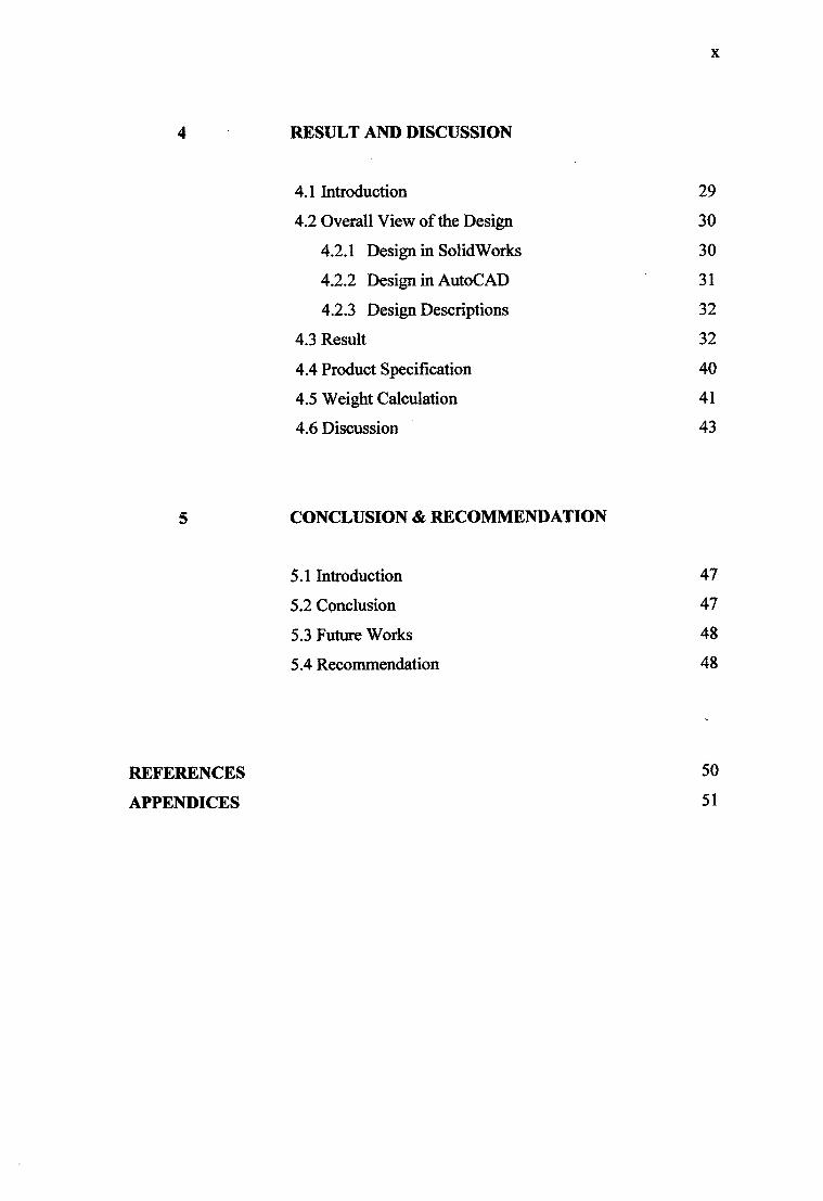
4 RESULT AND DISCUSSION
4.1 Introduction 29
4.2 Overall View of the Design 30
4.2.1 Design in SolidWorks 30
4.2.2 Design in AutoCAD 31
4.2.3 Design Descriptions 32
4.3 Result 32
4.4 Product Specification 40
4.5 Weight Calculation 41
4.6 Discussion 43
5 CONCLUSION & RECOMMENDATION
5.1 Introduction 47
5.2 Conclusion 47
5.3 Future Works 48
5.4 Recommendation 48
REFERENCES 50
APPENDICES 51

LIST OF FIGURES
FIGURE NO. TITLE PAGE
2.1 Craftsman 4 Drawer Roll Away Tool Box 6
Garage Storage
2.2 Draper 5 Drawer Roller Cabinet 7
2.3 Sealey AP4362 Topchest 6 Drawer 2 Shelf Red 8
2.4 Punching Process 9
2.5 MIG Welding 11
2.6 A GMAW wire feed unit 11
2.7 TrumaBend V85S Machine 13
3.1 Project Flow Chart 15
3.2 Concept A (Datum concept) 19
3.3 Concept B 19
3.4 Concept C 20
3.5 Concept 21
4.1 Framework of Transparent Trolley Toolbox 30
4.2 Transparent Trolley Toolbox 30
4.3 AutoCAl) design to cutting sheet metal 31
4.4 Measuring Process 33
4.5 Cutting Process 33
4.6 Welding Process 34
4.7 Converting Process 34
4.8 Punching Process 35
4.9 Bending Process 35
4.10 Cutting Laser Process 36
4.11 Drilling and Riveting Process 37
xi
xli
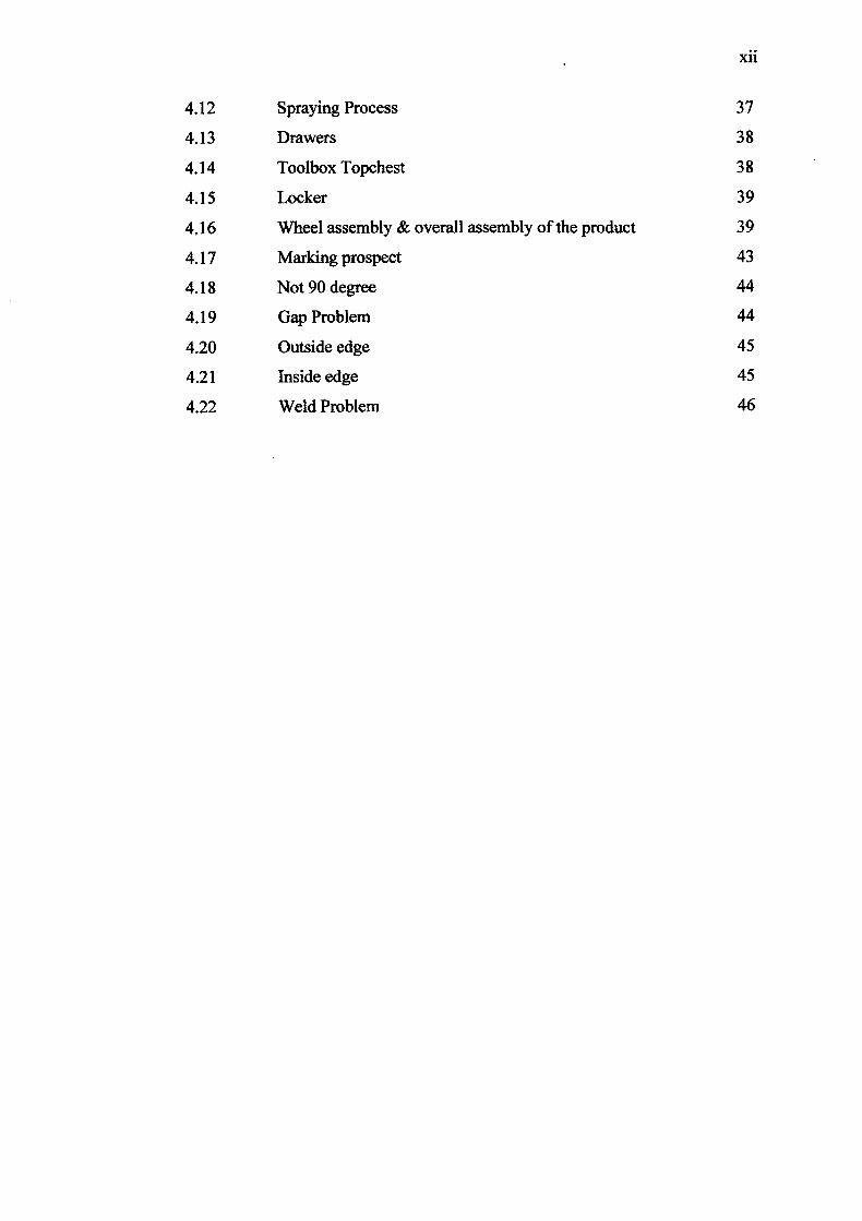
4.12 Spraying Process 37
4.13 Drawers 38
4.14 Toolbox Topchest 38
4.15 Locker 39
4.16 Wheel assembly & overall assembly of the product 39
4.17 Marking prospect 43
4.18 Not 90 degree 44
4.19 Gap Problem 44
4.20 Outside edge 45
4.21 Inside edge 45
4.22 Weld Problem 46

LIST OF TABLES
TABLE NO. TITLE PAGE
1.1 Project Schedule 4
3.1 Concept Generation and Evaluation 22
3.2 Transparent Trolley Toolbox Process 24
3.3 Material specifications 26
4.1 Product Specification 40
xlii

LIST OF APPENDICES
APPENDIX TITLE PAGE
A SolidWorks drawing part by part 51
B Prospect part by part
C Toolbox assembly 71
xiv
CHAPTER 1
INTRODUCTION
1.1 Project Synopsis
This project is about development of transparent trolley toolbox. It will show
the differences of the toolbox at the current market product with the transparent
trolley toolbox. In this semester (Semester 1 07/08), to complete this task, the CNC
(Computer Numerical Control) Turret Punching and CNC Bending Machine need to
be run perfectly. As the Diploma final year project allocates the duration of one
semester, and the project must finish and achieve the target. This project also to
make sure the student have knowledge and skills to operate the machine and know
how to use their understanding to overcome the problem that have occur.
1.2 Problem Statement
Generally, the sheet metal toolbox is high mass than the plastic toolbox [1].
So by combining the sheet metal and plastic toolbox became one trolley toolbox that
will call as name the transparent toolbox. This transparent toolbox has less mass than
the sheet metal toolbox. The other toolbox also difficult to see directly inside of the
toolbox because the obstacle from the sheet metal wall. However, the metal known
for being high strength than plastic, so one should balance its disadvantages against
the need to withstand abuse and support the weight of many tools.

2
1.3 Project Objectives
This project is to make the toolbox that has commonly in market normally is
sheet metal to become the transparent at the certain side. The toolbox is combination
of sheet metal and prospect plastic. This project is apply the lesson and
knowledgeable that we learn before. It can practice the skill and solving the problem
using academic study. This project also, to enhance a student skill and ability to work
individually. It also gives me, an experience and knowledge. The project is aimed to
improve productivity or yield. It is a continuous improvement activity of toolbox. So
the objectives of this project are:
i. To design and development transparent toolbox.
ii. To store and to keep the laboratory equipment.
iii. To setting up and running CNC Turret Punching and CNC Bending
Machine.
iv. The transparent toolbox allows people to see whatever equipment inside
the toolbox.
1.4 Project Scopes
This project is aim to improve the transparent toolbox being something
difference than has at the market nowadays. This product has their specification and
feature. The scopes of the product are:-
i. Design and develop transparent toolbox.
ii. This toolbox has four drawers. The first one is top drawer. Another three
is front drawer which is has different sizes.
iii. This toolbox is safe because there are no sharp edges.
iv. There is wheel that can make it moves everywhere.
V. This toolbox dimension is 750 x450x850 [length (L) x width (W) x height
(H)] in millimeter (mm).

3
13 Project Background
A toolbox, also known as a tool chest, varies with the craft of the owner. The
purpose of the toolbox is to organize, carry, and protect the owner's tools used for
trade, hobby [1]. Most of the toolbox at the market product consist of sheet metal
with different sizes and feature. But no one consist with transparent plastic that make
easier to see inside the toolbox. Sometimes, the worker find it difficult to find any
tool and equipment and according this transparent toolbox it also will make easier to
find any tool and equipments. It also portable because it has wheel that make it
moves everywhere.
1.6 Project Schedule
The project is the schedule planning for making the Transparent Trolley
Toolbox. It was start from week I until week 14. The first activity is to search the
information related to the toolbox whether in internet or the references book. The
following activities were proceeding with the activities that showed in Table 1.1.
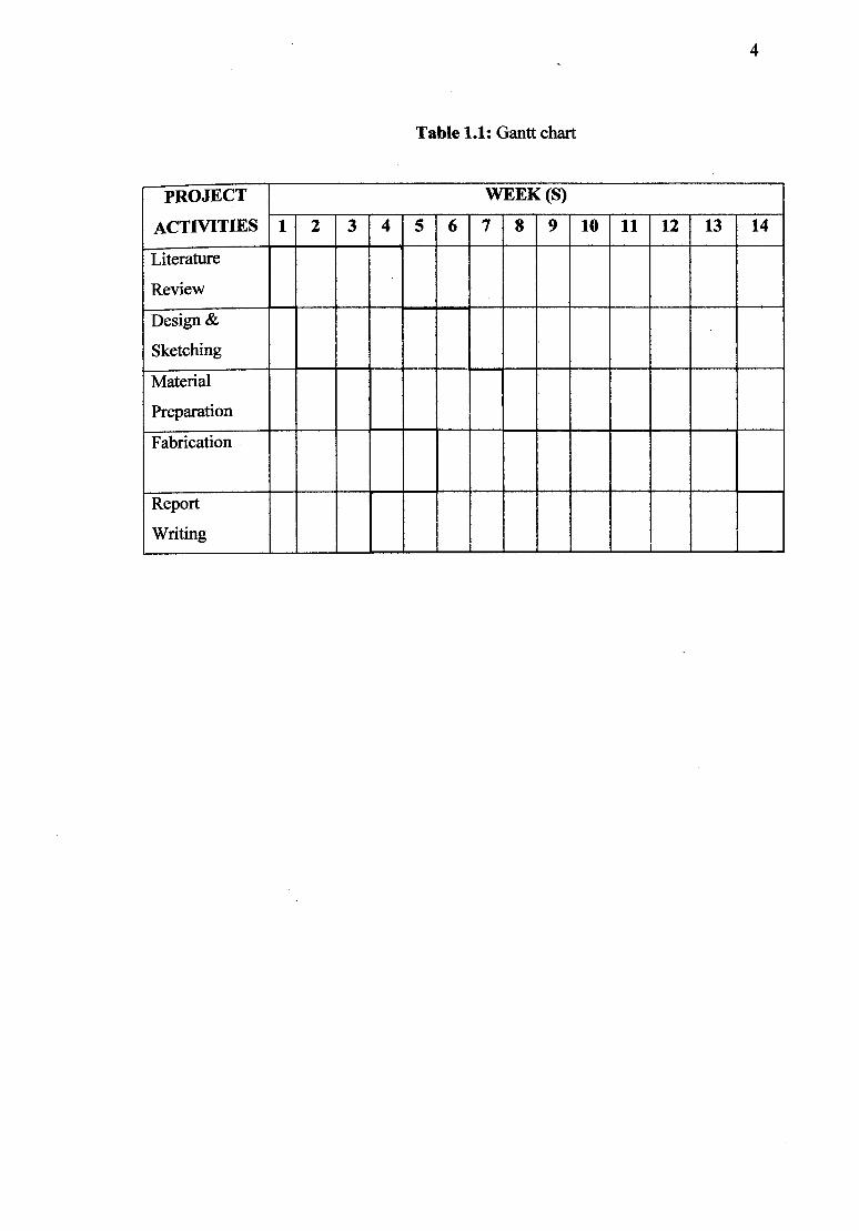
Table 1.1: Gantt chart
PROJECT WEEK (S)
ACTIVITIES 1 2 3 4 5 1 6 7 8 9 10 11 12 13 14
Literature
Review
Design &
Sketching
Material
Preparation
Fabrication
Report
Writing
CHAPTER 2
LITERATURE STUDY
2.1 Introduction
The transparent toolboxes also know as the transparent trolley toolbox
because it functions is to use a trolley vehicle to go from one place to another. The
basic of this toolbox is because of their post or their framework. The post is made
same as the trolley because of that it calls the transparent trolley toolbox. This
toolbox use the trolley as their basic component so that it can accommodate and
allowed man to store whether their small or heavy items. This transparent trolley
toolbox will help man to do their work without use much force to move the toolbox
although have heavy load. This transparent toolbox is making especially foruse in
laboratory or workshop that has security escort that very tight and strong. It is
because this toolbox make by transparent plastic at the certain side and it easy to
crack and wreak. It also made the toolbox container easy to steal by someone. That
why this toolbox mostly will be in workshop and laboratory. In this chapter, it will
show the few toolboxes in market as their comparison.
2.2 Product review
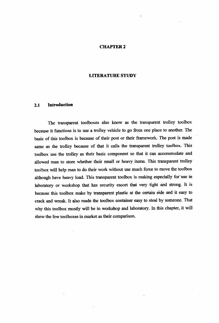
2.2.1 Craftsman 4 Drawer Roll Away Tool Box Garage Storage
This item is dents on the right side, back side and a few dents on the front.
There are some scratches and scuffs here and there. The dent's are only cosmetic
flaws and does not affect the functions of this box. The lock and drawers are fully
functional. This product comes with 1 key, top rubber material and the paperwork. It
is does not include the 2nd key or the retail box. Shell and drawers have black baked
enamel finish with platinum molded plastic handles, full-extension drawers,
compound-action drawer slides, internal locking system with I over molded
reversible key, a top rubber material with the Craftsman logo and 10x5 mm swivel
casters. The toolbox dimension is 675W x 457D x 800H mm with casters. The
product was showed in Figure 2.1. [2]
Figure 2.1: Craftsman 4 Drawer Roll Away Tool Box Garage Storage [2]
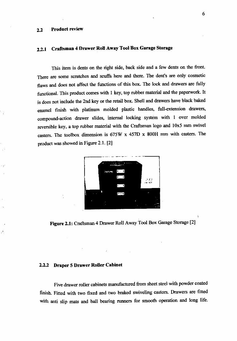
2.2.2 Draper 5 Drawer Roller Cabinet
Five drawer roller cabinets manufactured from sheet steel with powder coated
finish. Fitted with two fixed and two braked swiveling castors. Drawers are fitted
with anti slip mats and ball bearing runners for smooth operation and long life.
7
Secure integral locking system supplied with two keys. Carton packed on pallet. The
configuration of this toolbox is 3 full width drawers with dimension 551 mm x 403
n x 75 mm and has 2 full width drawers with dimension 551 mm x 403 mm x 155
mm. This Draper 5 Drawer Roller Cabinet was showed in Figure 2.2. [3]
Figure 2.2: Draper 5 Drawer Roller Cabinet [3]
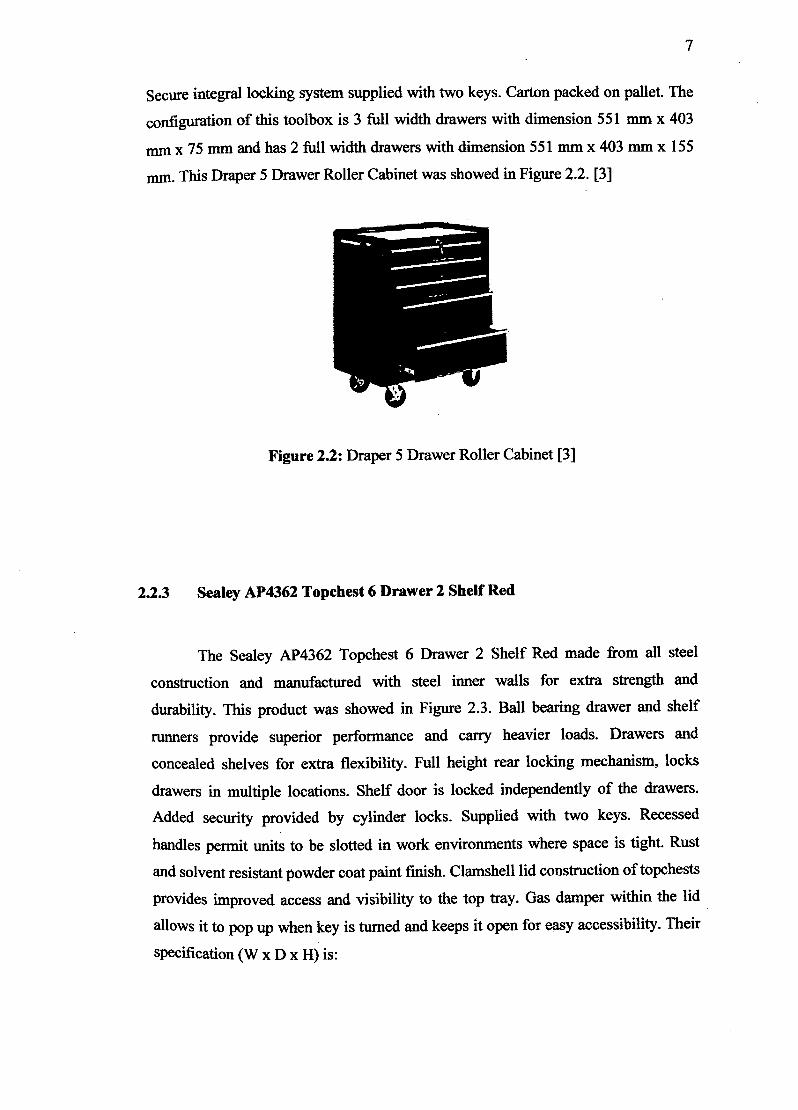
2.2.3 Sealey AP4362 Topchest 6 Drawer 2 Shelf Red
The Sealey AP4362 Topchest 6 Drawer 2 Shelf Red made from all steel
construction and manufactured with steel inner walls for extra strength and
durability. This product was showed in Figure 2.3. Ball bearing drawer and shelf
runners provide superior performance and carry heavier loads. Drawers and
concealed shelves for extra flexibility. Full height rear locking mechanism, locks
drawers in multiple locations. Shelf door is locked independently of the drawers.
Added security provided by cylinder locks. Supplied with two keys. Recessed
handles permit units to be slotted in work environments where space is tight. Rust
and solvent resistant powder coat paint finish. Clamshell lid construction of topchests
Provides improved access and visibility to the top tray. Gas damper within the lid
allows it to pop up when key is turned and keeps it open for easy accessibility. Their
specification (W x D x H) is:
8
Overall size : 1045 x 450 x 530mm
Small Drawer (x4) 540 x 420 x 50mm
Medium drawer (x2) 540 x 420 x 90mm
Shelf (x2) 300 x 370 x 50mm [4]
Figure 2.3: Sealey AP4362 Topehest 6 Drawer 2 Shelf R [4]
2.3 Basic Parts
i. Body For workshop use that requires full strength of body. Normally, the frame
or body was made by using sheet metal. Body of trolley toolbox usually
consists of drawer with variation of sizes.
ii. Handle
Generally, all the trolley must have handled to provide less effort while
using the trolley due to heavy loading. But the designs for each trolley
toolbox is different from one another depend on the manufacturers.
iii. Wheel
Normally made from high quality rubber. The wheel can join together
with the screws and nut with steel frame to ensure strength.
2.4 Machining Process
2.4.1 Punching Process
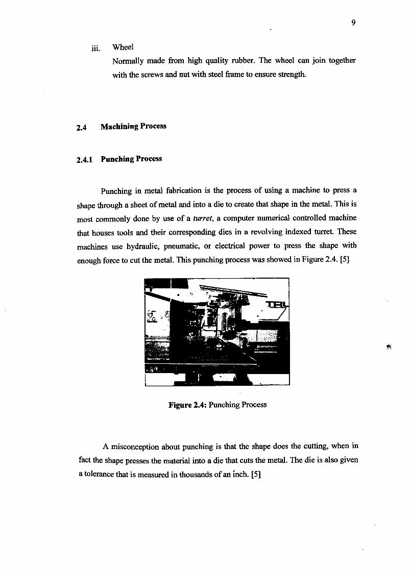
Punching in metal fabrication is the process of using a machine to press a
shape through a sheet of metal and into a die to create that shape in the metal. This is
most commonly done by use of a turret, a computer numerical controlled machine
that houses tools and their corresponding dies in a revolving indexed turret. These
machines use hydraulic, pneumatic, or electrical power to press the shape with
enough force to cut the metal. This punching process was showed in Figure 2.4. [5]
Figure 2.4: Punching Process
A misconception about punching is that the shape does the cutting, when in
fact the shape presses the material into a die that cuts the metal. The die is also given
a tolerance that is measured in thousands of an inch. [5]
10
• Punching can be better understand as pressing the material against a die with
a huge force, this force pushes the material into the die and shears off the waste
material. The turret punch machine specifications that have in mechanical laboratory
are:
Model
Type
Fuse
Power Supply
Connected load
Control voltage
Max. Punch capacity
Trumpf Trumatic 2020R
Tc 2020R
3 x 40A
415 V/SOHz
22kVA
24VDC
l8OkN
2.4.2 Welding Process
Welding is a fabrication process that joins materials, usually metals or
thermoplastics. This is often done by melting the steels and adding a filler material to
form a pool of molten material (the weld puddle) that cools to become a strong joint,
with pressure sometimes used in conjunction with heat, or by itself, to produce the
weld.
2.4.2.1 Introduction of GMAW
Gas metal arc welding (GMAW), sometimes referred to by its subtypes metal
inert gas (MIG) welding or metal active gas (MAG) welding, is a semi-automatic or
automatic arc welding process in which a continuous and consumable wire electrode

I and a shielding gas are fed through a welding gun. A constant voltage, direct current
power source is most commonly used with GMAW, but constant current systems, as
well as alternating current, can be used. The MIG welding was showed in Figure 2.5.
[6]
Figure 2.5: MIG Welding
2.4.2.2 Equipment of MIG Welding
To perform gas metal arc welding, the basic necessary equipment is a
welding gun, a wire feed unit, a welding power supply, an electrode wire, and a
shielding gas supply. The Figure 2.6 below showed the GMAW wire feed unit. [6]
Figure 2.6: A GMAW wire feed unit

12
2.4.23 The Advantages and disadvantages of MIG Welding
The advantages of MIG welding are it can produce high productivity of
product. It is because based on this machine the consumer no need to stop their work
to change rods or chip and brush the weld frequently. MIG welding also easy to learn
and makes great-looking welds. It also can weld various types of material such as
stainless steel, mild steel, and aluminums. This welding process also can be weld in
all positions. For their disadvantages, this MIG weld needs a lot of cost money that
consumable such as tips and nozzles. The welding is not worth a dang on paint, rust,
or dirty surfaces. This welding also not good for thick steel, because it does not get
the proper penetration. It also make the surface of the material was damaged because
their heat not suitable for the thick surfaces. [6]
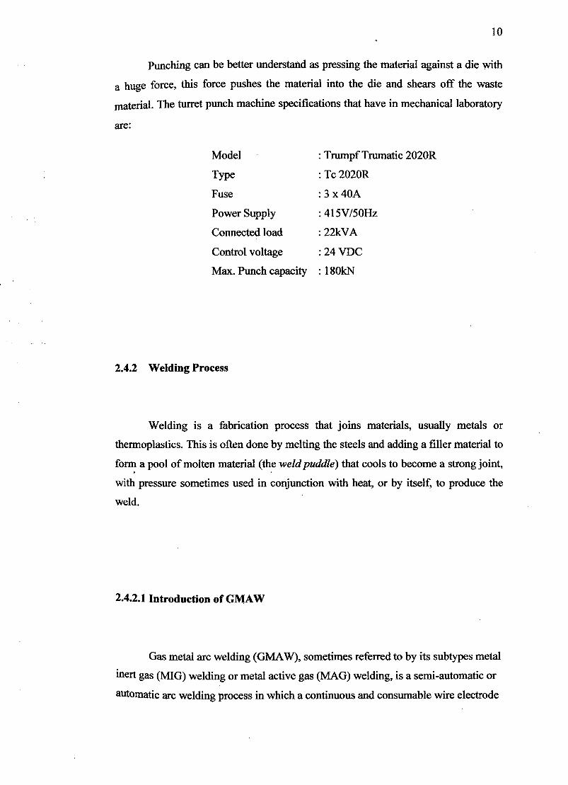
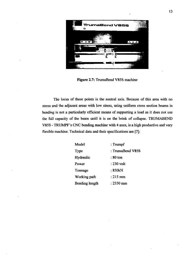
2.4.3 Bending Process
The bending (also known as flexure) characterizes the behavior of a structural
element subjected to a lateral load. A structural element subjected to bending is
known as a beam. A closet rod sagging under the weight beam is being compressed
while the material at the bottom is being stretched. There are three notable internal
forces caused by lateral loads shear parallel to the lateral loading, compression along
the top of the beam, and tension along the bottom of the beam. These last two forces
form a couple or moment as they are equal in magnitude and opposite in direction.
This bending moment produces the sagging deformation characteristic of
compression members experiencing bending. The compressive and tensile forces
induce stresses on the beam. The maximum compressive stress is found at the
uppermost edge of the beam while the maximum tensile stress is located at the lower
edge of the beam. Since the stresses between these two opposing maxima vary
linearly, there therefore exists a point on the linear path between them where there is
no bending stress. The machine was showed ' in Figure 2.7. [7]
13
Figure 2.7: TrumaBend V85S machine
The locus of these points is the neutral axis. Because of this area with no
stress and the adjacent areas with low stress, using uniform cross section beams in
bending is not a particularly efficient means of supporting a load as it does not use
the full capacity of the beam until it is on the brink of collapse. TRUMABEND
V85S - TRUMPF's CNC bending machine with 4 axes, is a high productive and very
flexible machine. Technical data and their specifications are [7]:
Model : Trumpf
Type : TrumaBend V85S
Hydraulic : 80 ton
Power : 230 volt
Tonnage : 850kN
Working path : 215 mm
Bending length : 2550 mm

[Q 10 W1 V DCAL
METHODOLOGY
3.1 Introduction
Project methodology is a body of practices, procedures and rules used by
those who work in a discipline or engage in an inquiry and a set of working methods.
This chapter will be discussed about methods and machining that will be use to make
the transparent trolley toolbox. All the methods that will be explained in this chapter
are very important procedure to ensure it follow the entire project schedule so that it
will be move smoothly. Effective methods will give clear view on how to do this
project. These methods will be guidance in so that it will be finish at the right time as
the planning. Whole process will be explained in this chapter also. So it will give
general view of what are the steps should be taken.
3.2 Project flow chart
In fabrication of the transparent trolley toolbox there is a planning of the
overall progress to assure the project can be finish follow on schedule.
For the diagram as shown Figure 3.1, the project starts with study and
gathers some information about the literature review and research related to the title.
This consist a review of the concept of trolley toolbox that have in market nowadays.
These tasks have been done through research on the internet, books and others
sources.