Design and Fabrication of Milling Vise Attachment on Lathe ...
9
© 2020 University College TATI (UC TATI). All rights reserved. Design and Fabrication of Milling Vise Attachment on Lathe Machine A. Muhammad Aziq Aznil 1 , A.A. Kamarul Adnan 1 1 Faculty of Engineering Technology, Manufacturing Engineering of the UCTATI, 24200 Kemaman, MALAYSIA. * Corresponding author: [email protected] KEYWORDS ABSTRACT Attachment Cost Design Fabricate Lathe Machine Milling Milling is a process performed with a machine in which the cutters rotate to remove the material from the work piece present in the direction of the angle with the tool axis. A lathe is a machine tool that rotates a work piece about an axis of rotation to perform various operations. By adding an attachment to a lathe machine, common milling operation such as plain milling, end milling and slotting can be performed. Having both milling and lathe machine can be highly cost in terms of machine cost and maintenance cost of the machines. It also took a large area to place the machine. The aim of the project is to improve the design of a machine that capable to perform the process of milling for the purpose of small and medium industries. The objectives of this project are to design an attachment on lathe machine to perform milling operation, to fabricate the milling attachment on lathe machine and to study the performance of the milling attachment on the lathe machine. Data collection is performed through software engineering. Personnel can assess and evaluate the process involve in more detail. It can be concluded that this milling attachment requires attaching and detaching easily. The cost of this attachment is less than to have both milling and lathe machine. 1.0 INTRODUCTION Milling is a process performed with a machine in which the cutters rotate to remove the material from the work piece present in the direction of the angle with the tool axis. Milling machine can perform common operations like plain milling, end-milling, slotting, turning, facing, fillet making, chamfering, drilling, gear cutting and slot cutting. A study will design and fabricate a vise attachment on a lathe machine to operate as a milling machine. In terms of the system cost and repair cost of the equipment, having both milling and lathe equipment can be extremely costly. A wide area was also required to position the computer in a tiny workshop. By attaching an attachment to a lathe machine to allow it to perform operations that can be performed by milling machines, this issue can be solved. Received 20 October 2020; received in revised form 20 November 2020; accepted 25 November 2020. International Journal of Synergy in Engineering and Technology Vol.1 No.2 (2020) 107-115
Transcript of Design and Fabrication of Milling Vise Attachment on Lathe ...

© 2020 University College TATI (UC TATI). All rights reserved.
Design and Fabrication of Milling Vise Attachment on Lathe Machine A. Muhammad Aziq Aznil 1, A.A. Kamarul Adnan 1
1 Faculty of Engineering Technology, Manufacturing Engineering of the UCTATI, 24200 Kemaman, MALAYSIA. *Corresponding author: [email protected] KEYWORDS ABSTRACT
Attachment Cost Design Fabricate Lathe Machine Milling
Milling is a process performed with a machine in which the cutters rotate to remove the material from the work piece present in the direction of the angle with the tool axis. A lathe is a machine tool that rotates a work piece about an axis of rotation to perform various operations. By adding an attachment to a lathe machine, common milling operation such as plain milling, end milling and slotting can be performed. Having both milling and lathe machine can be highly cost in terms of machine cost and maintenance cost of the machines. It also took a large area to place the machine. The aim of the project is to improve the design of a machine that capable to perform the process of milling for the purpose of small and medium industries. The objectives of this project are to design an attachment on lathe machine to perform milling operation, to fabricate the milling attachment on lathe machine and to study the performance of the milling attachment on the lathe machine. Data collection is performed through software engineering. Personnel can assess and evaluate the process involve in more detail. It can be concluded that this milling attachment requires attaching and detaching easily. The cost of this attachment is less than to have both milling and lathe machine.
1.0 INTRODUCTION Milling is a process performed with a machine in which the cutters rotate to remove the material from the work piece present in the direction of the angle with the tool axis. Milling machine can perform common operations like plain milling, end-milling, slotting, turning, facing, fillet making, chamfering, drilling, gear cutting and slot cutting. A study will design and fabricate a vise attachment on a lathe machine to operate as a milling machine.
In terms of the system cost and repair cost of the equipment, having both milling and lathe equipment can be extremely costly. A wide area was also required to position the computer in a tiny workshop. By attaching an attachment to a lathe machine to allow it to perform operations that can be performed by milling machines, this issue can be solved.
Received 20 October 2020; received in revised form 20 November 2020; accepted 25 November 2020.
International Journal of Synergy in Engineering and Technology Vol.1 No.2 (2020) 107-115

The project aims to develop the design of a machine capable of performing the milling process for small and medium-sized industries. The aims of this project are to design an attachment on the lathe machine to perform the milling operation, to produce the lathe machine's milling attachment, and to research the lathe machine's milling attachment efficiency. Design and manufacture of an attachment system on the lathe machine and this attachment system applicable to traditional lathe machines are the scope of research of this project.
The design of the milling attachment will be done by using Autodesk Inventor 2019 software. This software enables us to view the assembled and dissembled part of the attachment part. The milling attachment will be assembled on the lathe machine. The performance of the attachment will be tested during milling operation perform on the lathe machine. In design concept area, we will find the best position for the milling attachment to be attached to the lathe machine. The milling attachment will be produced to test it functionality. The milling attachment will be build using existing parts and machining new parts. The existing parts will be from scrap or from buying new one. 2.0 METHODOLOGY
The concept and design for the product was gathered from the brainstorming and research process. During the research process, observation on current skill was made. The milling attachment need to be attached on the lathe machine. Thus, various aspects need to be considered for the positioning of the attachment which are easy to attach and detach the milling attachment and the movement of axis for the milling attachment. Thus, the positioning of the milling attachment is decided to be on top of the cross slide of the lathe machine. This will enable the attachment to move on three axis; x, y and z. The carriage of the lathe machine will move as x axis. The cross slide of the lathe machine will move as y axis. The compound rest attached on the milling attachment will move as z axis.
Figure 1: Design using Autodesk Inventor Software.
© 2020 University College TATI (UC TATI). All rights reserved. 108
International Journal of Synergy in Engineering and Technology Vol.1 No.2 (2020) 107-115

CRITERIA
1 2 3
PAST DESIGN A
PAST DESIGN B
NEW DESIGN
EASY TO OPERATE + ++ ++
FAST OPERATION + ++ ++
CHANGEABILITY + + ++
MAINTAINANCE COST 0 0 0
USER FRIENDLY + ++ ++
SAFETY + + +
TOTAL MARKS 5 8 9
RANK 3 2 1
MARKS DESCRIPTION
++ EXCELLENT
+ GOOD
0 MEDIUM
- BAD
-- WORST
Table1:DesignSelectionTable.
Table2:DesignMarksDistribution.
© 2020 University College TATI (UC TATI). All rights reserved. 109
International Journal of Synergy in Engineering and Technology Vol.1 No.2 (2020) 107-115
Material that will be used in this project is DF3 tool steel. DF-3 general purpose oil-hardening tool steel is a versatile manganese-chromium-tungsten steel suitable for a wide variety of cold-work applications. Its main characteristics include:
i. Good machinability ii. Good dimensional stability in hardening iii. A good combination of high surface hardness and toughness after hardening and
tempering. These characteristics combine to give a steel suitable for the manufacture of tooling with good tool-life and high production economy.
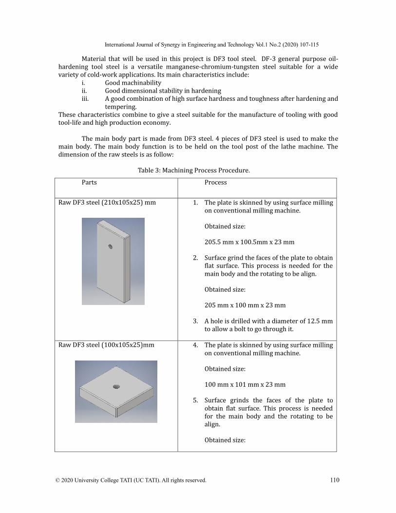
The main body part is made from DF3 steel. 4 pieces of DF3 steel is used to make the main body. The main body function is to be held on the tool post of the lathe machine. The dimension of the raw steels is as follow:
Parts Process
Raw DF3 steel (210x105x25) mm
1. The plate is skinned by using surface milling on conventional milling machine.
Obtained size:
205.5 mm x 100.5mm x 23 mm
2. Surface grind the faces of the plate to obtain flat surface. This process is needed for the main body and the rotating to be align.
Obtained size:
205 mm x 100 mm x 23 mm
3. A hole is drilled with a diameter of 12.5 mm to allow a bolt to go through it.
Raw DF3 steel (100x105x25)mm
4. The plate is skinned by using surface milling on conventional milling machine.
Obtained size:
100 mm x 101 mm x 23 mm
5. Surface grinds the faces of the plate to obtain flat surface. This process is needed for the main body and the rotating to be align.
Obtained size:
Table3:MachiningProcessProcedure.
© 2020 University College TATI (UC TATI). All rights reserved. 110
International Journal of Synergy in Engineering and Technology Vol.1 No.2 (2020) 107-115
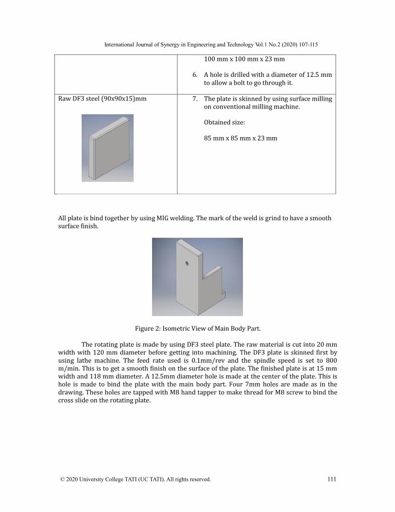
100 mm x 100 mm x 23 mm
6. A hole is drilled with a diameter of 12.5 mm to allow a bolt to go through it.
Raw DF3 steel (90x90x15)mm
7. The plate is skinned by using surface milling on conventional milling machine.
Obtained size:
85 mm x 85 mm x 23 mm
All plate is bind together by using MIG welding. The mark of the weld is grind to have a smooth surface finish.
Figure 2: Isometric View of Main Body Part.
The rotating plate is made by using DF3 steel plate. The raw material is cut into 20 mm width with 120 mm diameter before getting into machining. The DF3 plate is skinned first by using lathe machine. The feed rate used is 0.1mm/rev and the spindle speed is set to 800 m/min. This is to get a smooth finish on the surface of the plate. The finished plate is at 15 mm width and 118 mm diameter. A 12.5mm diameter hole is made at the center of the plate. This is hole is made to bind the plate with the main body part. Four 7mm holes are made as in the drawing. These holes are tapped with M8 hand tapper to make thread for M8 screw to bind the cross slide on the rotating plate.
© 2020 University College TATI (UC TATI). All rights reserved. 111
International Journal of Synergy in Engineering and Technology Vol.1 No.2 (2020) 107-115

Figure 3: Isometric View of Rotating Plate Part.
Figure 4: Exploded View of Full Assembly.
The performance of milling attachment on lathe machine was tested for its accuracy and precision to perform milling operation same as an actual milling machine. Analysis was collected based on observation on the error margin and differences in measurement during machining and the table will provide as shown as figure below. The feed rate and spindle speed will remain constant.
The first method used is by using end milling operation. Three size of end mill which are diameter 4 mm, 6 mm and 8 mm. Each size of end mill undergo three reading taken for both
© 2020 University College TATI (UC TATI). All rights reserved. 112
International Journal of Synergy in Engineering and Technology Vol.1 No.2 (2020) 107-115

conventional milling machine and milling vise attachment. The parameter for each run is constant. The three reading is to find the average of each size. Error is calculated by finding the percentage of difference between the reading of conventional milling machine and the milling vise attachment to the conventional milling machine reading. The result is measured by digital vernier calliper.
The second method used is by using drilling operation. Three size of drill bit which are diameter 6 mm, 8 mm and 12 mm. Each size of drill bit undergo three reading taken for both conventional milling machine and milling vise attachment. The parameter for each run is constant. The three reading is to find the average of each size. Error is calculated by finding the percentage of difference between the reading of conventional milling machine and the milling vise attachment to the conventional milling machine reading. The result is measure by using digital vernier calliper.
The third method used is by using surface milling operation. Three depth of cut in a single feed which are 1mm, 2mm and 3mm. Each depth of cut undergo three reading taken for both conventional milling machine and milling vise attachment. The parameter for each run is constant. The three reading is to find the average of each size. Error is calculated by finding the percentage of difference between the reading of conventional milling machine and the milling vise attachment to the conventional milling machine reading.
3.0 RESULTS AND DISCUSSION
This fabricate was created according to the objective, problem statement, idea and the design of selection. This experiment is to measure the error margin between milling machine and milling attachment on lathe machine. After that, the result will be collected by the method of cut on work piece that was taken from 3 parameter of cut (Length, Radius, and Depth). The experiment that has a good progress and did not any problem and all the data was recorded.
a) b)
c) d) Figure 5: a) Isometric view of full assembly, b) Front view of full assembly, c) Side view of full
assembly, d) Top view of full assembly.
© 2020 University College TATI (UC TATI). All rights reserved. 113
International Journal of Synergy in Engineering and Technology Vol.1 No.2 (2020) 107-115

Method 1: End Milling
Diameter 4mm Diameter 6mm Diameter 8mm
Error: 0.1594% 0.0598% 0.0933%
Method 2: Drilling
Diameter 6mm Diameter 8mm Diameter 12mm
Error: 0.1702% 0.0749% 0.119%
Method 3: Surface Milling
Depth 1mm Depth 2mm Depth 3mm
Error: 0.0998% 0.0249% 0.0066%
From Table 4, the percentage of difference between actual milling machine and milling vise attachment is low which less than 1%. The difference of the measurement can be caused by several elements such as machine capability and vibration during machining. However, the low percentage of difference proves that the milling vise attachment is useable, and it is up to the skill of the machinist to obtain the correct measurement.
4.0 CONCLUSION As the conclusion for design and fabrication of milling attachment on lathe machine, in this modern world the cost for maintenance and having various machine in a workshop will cost much. So, a new machine has been designed, fabricated and named as “QCDC Milling Attachment”.
By comparing with many types of existing methods, includes traditional, manual, and automatic, it can be concluded that this milling attachment requires to attach and detach easily, and the cost of this attachment are less than to have both milling and lathe machine. This is importance to give towards user friendly in operation, decrease the cost of maintenance and the objective of this project will be achieved after the project completed.
The difference of the reading is also low which less than 1%. Thus, this attachment is valid to be used for basic milling operation. Lastly, the operation of this attachment can be used to perform small scale milling operation on lathe machine and depends on the skill of user. The objectives of the study are achieved.
Table4:SummaryofResult.
© 2020 University College TATI (UC TATI). All rights reserved. 114
International Journal of Synergy in Engineering and Technology Vol.1 No.2 (2020) 107-115
Finally, as for the recommendations there are a few recommendations for the future research, which are:
i. Introducing a motorized attachment to ease up user to move the axis of the attachment.
ii. Design and fabricate new axis for the tools in the future that can make the tools more flexible depending the size of the work piece itself.
ACKNOWLEDGEMENT
The authors gratefully acknowledge the support of the lecturers from the Faculty of Engineering Technology of the UCTATI. REFERENCES Allan Lee,Alison Legood, David Hughes,Amy Wei Tian, Alexander Newman & Caroline Knight
Leadership, creativity and innovation: a meta-analytic review, 2019. Brighthub Engineering, What is a Lathe Machine? History, Parts, and Operation,. 2018. Edison, H., Ali, N.B., & Torkar, R., Towards innovation measurement in the software industry,
2014. Haan, E. R., Selecting and using a bench vise, 2011. Madsen, David A., Engineering Drawing & Design, 2012. Merriam-Webster, Innovation ,2016. Mihaela Diaconu, Technological Innovation: Concept, Process, Typology and Implications in the
Economy, 2011. Serope Kalpakjian, Steven Schmid, Manufacturing Processes for Engineering Materials, 2008. Stephen P. Radzevic, Dudley's Handbook of Practical Gear Design and Manufacture, 2012.
© 2020 University College TATI (UC TATI). All rights reserved. 115
International Journal of Synergy in Engineering and Technology Vol.1 No.2 (2020) 107-115


![Milling Operations in the Lathe [Workshop Practice Series 05] - T. Cain (Argus, 1984) WW](https://static.fdocuments.in/doc/165x107/547ef624b4af9f7e468b481c/milling-operations-in-the-lathe-workshop-practice-series-05-t-cain-argus-1984-ww.jpg)