Design and Fabrication of a Ring-Stiffened Graphite … LIBRARY KAFB, NM NASA Contractor Report 3026...
80
- NASA Contractor Report 3026 Design and Fabrication of a Ring-Stiffened Graphite-Epoxy Corrugated Cylindrical Shell Read Johnson, Jr. CONTRACT NASl-14547 AUGUST 1978 IWEA ’ :_ .’ . . ^ L’ :. https://ntrs.nasa.gov/search.jsp?R=19780023522 2018-07-01T20:03:34+00:00Z
Transcript of Design and Fabrication of a Ring-Stiffened Graphite … LIBRARY KAFB, NM NASA Contractor Report 3026...

-
NASA Contractor Report 3026
Design and Fabrication of a Ring-Stiffened Graphite-Epoxy Corrugated Cylindrical Shell
Read Johnson, Jr.
CONTRACT NASl-14547 AUGUST 1978
IWEA ’
:_ .’ . . ^
L’ :.
https://ntrs.nasa.gov/search.jsp?R=19780023522 2018-07-01T20:03:34+00:00Z

-
TECH LIBRARY KAFB, NM
NASA Contractor Report 3026
Design and Fabrication of a Ring-Stiffened Graphite-Epoxy Corrugated Cylindrical Shell
Read Johnson, Jr. McDowell Doughzs Astronautics Company Huntington Beach, California
Prepared for Langley Research Center under Contract NASl-14547
National Aeronautics and Space Administration
Scientific and Technical Information Office
1978


CONTENTS
Section 1
Section 2
Section 3
Section 4
Section 5
Section 6
INTRODUCTION AND SUMMARY . . . . . . 1
TEST CYLINDER DESIGN AND ANALYSIS . . . . . . . . . . . . . . . . . 5
. 2.1 Design Approach ........... 7 2.2 Shell Buckling Analysis and Ring-
Stiffener Design ........... 13 2.3 Detailed Design of Shell ....... 16 2.4 Design Development Tests ...... 18
SUBELEMENT TEST PANELS. . . . . . . . 29
3. 1 Panel Designs ............ 29 3. 2 Panel Fabrication and Non-
destructive Tests. .......... 32 3. 3 Panel Test Results .......... 44
CYLINDER TOOLING AND FABRICATION. . . . . . . . . . . . . . . . 55
4. 1 Full-Size Panel Fabrication . . . . . 55 4.2 Ring-Stiffener Fabrication - . . . . l 60 4. 3 Assembly Jig. . . . . . . . . . . . . 61 4. 4 Cylinder Assembly . . . . . . . . . . 63
CYLINDER COST AND WEIGHT ANALYSIS . . . . . . . . . . . . . . . . . . 69
5. 1 Cost Analysis. ............ 69 5.2 Weight Analysis ........... 70
CONCLUSIONS. . . . . . . . . . . . . . . . 73
REFERENCES. . . . . . . . . . . . . . . . 75
iii

Section 1
INTRODUCTION AND SUMMARY
The objectives of the program reported here are to advance lightweight
composite shell design technology and evaluate appropriate design and
analysis procedures For lightweight composite shells that must satisfy
buckling requirements. To accomplish those objectives, the primary
effort was to design and fabricate a graphite-epoxy cylindrical shell 3. 05m
(10 ft) in diameter by 3. 05m (10 ft) long for evaluation in shell bending
tests to be conducted by the Structures and Dynamics Division of the NASA
Langely Research Center. Through such tests, the use of advanced composite
materials will be evaluated for structural applications in future space
missions such as those that involve spacecraft and structural assemblies to
be used in geosynchronous missions. Spacecraft for such missions will
require ultralightweight structures to achieve maximum payloads. Of equal
importance is the requirement to provide designs that are cost-competitive
with current structural approaches. For space structures that must resist
buckling under compression or shell bending loads, composite materials offer
an attractive approach for providing lightweight, low-cost structural com-
ponents for future spacecraft. In recognition of the potential weight savings
available through structural applications of graphite-epoxy materials, an
earlier test program (Reference 1) was undertaken by the NASA to provide a
technology base for flat, stiffened graphite-epoxy compression panels and to
evaluate their effectiveness in reducing structural weight. The panels used
in the earlier test program were designed using an advanced version of the
analytical methods developed in Reference 2. Other tests were conducted with
stiffened graphite-epoxy shear panels. The encouraging results achieved in
prior efforts led to establishment of the current program to develop and
evaluate appropriate design and analysis procedures for lightweight composite
shells that must satisfy buckling requirements. The work conducted under this
program is part of an overall effort by the NASA to evaluate advanced com-
posite materials with which to achieve more efficient shell structures for
application in future spacecraft.

The program described here was conducted over a total time span of 18
months, the test cylinder being delivered at the end of 18 months. In the
initial portion of the program, the cylinder design was used as a basis to
design and fabricate three types of subsize test panels; those panels were
then tested in compression at the Langley Research Center to verify critical
design features of the cylinder. During that portion of the program, tests
were also conducted by MDAC to further define material properties, to verify
the attachment joint that introduces the bending moment loads into the cylin-
der at each end, and to confirm the stiffness properties of the selected stiffen-
ing ring cross section, Eight subsize panels were fabricated and tested in
compression, four panels being 0. 61m (24 in.) long by 0.46m i18 in.) wide,
two being 0. 91m (36 in.) long and 0. 46m (18 in.) wide, and the final two
being 2. 54m (100 in.) long and 0. 94m (37 in.) wide. All test panels were
designed with the full-size corrugation cross section of the shell wall. The
0.61m panels were used to evaluate local buckling of the corrugation ele-
ments, and the 0.91m panels were designed to evaluate the shell wall joint
areas and the attachment joints at the cylinder ends. The 2.54m panels .were
tested in compression to determine the buckling characteristics of panels
approximating the length of the cylinder and to evaluate the ring stiffener
attachment to the corrugated wall. Tests of the 0.61m panels resulted in
increasing the thickness of the corrugation crowns by one ply of material, a
change that resulted in satisfactory local buckling behavior in the shell wall.
No other changes were required as a result of the subsize panel tests. The
fabricated shell wall panels had an average weight of 0.0156 kg/m‘ (0.37
lbm/ft’), a weight that was computed to be approximately 23% lower than a
comparable aluminum design.
Specific secondary objectives of the program included evaluations of weight,
strength, production methods, and production costs of a lightweight graphite-
epoxy cylindrical shell simulating the size and load-carrying ability of shell
structures projected for future spacecraft. Weight, production methods,
and production costs are evaluated hereinj test results of the full-size
cylinder will be reported separately in a NASA document.
2

The program was managed by Read Johnson, Jr., under the direction of
Dr. J. F. Gabribotti, Chief Technology Engineer, Structures and Materials.
Major contributions were made to the program by V. L. Freeman and
J. K. Donahoe, of Non-Metallic Materials, Structures and Materials. Others
who contributed significantly are M. H. Schneider, Jr. and S. J. Kong, of
Structures, Structures and Materials, and Dr. C. D. Babcock, of the
California Institute of Technology.
Use of commercial products or names of manufacturers in this report does
not constitute official endorsement of such products or manufacturers, either
expressed or implied, by the National Aeronautics and Space Administration.

Section 2
TEST CYLINDER DESIGN AND ANALYSIS
The cylindrical shell wall configuration was selected by NASA based upon
extensive composite shell analysis efforts and correlation of composite flat
panel test results with analytically predicted panel failures (Reference 1 and
2). Figure 1 summarizes the comparisons between aluminum and graphite-
epoxy panels tested in compression and the theoretically predicted perform-
mance by plotting the weight parameter W/AL as a function of the load para-
meter N,/ L. The lower weight achieved by graphite-epoxy panels at equiva-
lent loadings for a given panel size is clearly shown in Figure 1.
A majority of the test panels described in Reference 1 were made from
Thorn’el 300/5208 graphite-epoxy prepreg material, thus providing extensive
data for that material. In addition, extensive coupon tests conducted by the
Douglas Aircraft Company (DAC) provided a comprehensive material data
base for T300/5208 tape material. For those reasons, T300/5208 was
chosen as the material for the shell wall and stiffening rings.
The selected shell wall incorporates an open-corrugation design stiffened
with external circumferential rings. While the basic shell wall corrugation
dimensions and laminate orientations were determined from NASA studies
and tests, the overall design approach and joint designs, the design of load-
introduction rings at the shell ends, and attachment of the ring stiffeners to
the shell wall were parts of the design effort conducted by MDAC. Similarly,
the cross-sectional stiffness characteristics of the ring stiffeners were de-
fined from NASA shell studies; however, the specific ring- stiffener cross
section was designed by MDAC.
5

500
100
A=BL / :. : : . . ,,::‘:“,”
,I NACA ALUMINUM DATA \
5
_ . EXPERIMENTAL -GRAPHITE-EPOXY HAT STIFFENED
. DESIGN:
0 A-l [k45 WEB1 A A-2 [+52 WEB] b A4 [FABRIC WEB1
2 n -. A-5 13 B-2 l S-1 [OPEN CORRUGATION]
1o-5 ’ I I 1 I fIllI I I I I11111 I I 0 ,111,
10 2 5 100 2 5 1,000 2 5 10,000
. :?jjj’ ‘ALUMINUM,’
1 I I I 11111l 1 III ! I I I Ill11
105 lo6 107 lo*
NJL (N/rn2)
Figure 1. Comparison of Structural Efficiencies of GraphiteEpoxy and Aluminum Compression Panels
6

2.1 DESIGN APPROACH
The shell selected for this program was designed to sustain a pure bending
moment of 1.150.x lo6 N-m (10.18 x lo6 in . -lb), resulting in a maximum
load intensity in the shell wall of 1, 576 N/cm (900 lb/in.). Preliminary
shell analyses were conducted with the aid of computer codes to establish
the corrugated wall geometry and define the required laminate construction.
The principal computer programs used to establish the optimum wall con-
figuration were BOSOR (Reference 3) and VIPASA (Reference 4), the former
program being used to predict overall shell failure modes and the latter being
used to predict local buckling modes as a function of load intensity and wall
configuration. The BUCLAP program (Reference 5) was also used by MDAC
as a further analytical method to evaluate local buckling of the shell wall
elements. Shell design requirements, including dimensional tolerances, are
summarized in Table 1. The shell configuration is shown in Figure 2.
The overall design of the shell with a 3. 05m (10 ft) diameter consists of an
open corrugated wall of 84 corrugations stiffened with four external rings
spaced at 0. 61m (24 in. ) intervals. The total length of the cylindrical shell
is 3. 15m (124 in. ), including the NASA-furnished steel loading rings, which
serve as connecting Lnterfaces with the test heads that apply the bending
moment to the shell. The 84 open corrugations running the length of the
cylinder have a pitch of 11. 400 cm (4.488 in. ) and a crown, or flat, width of
3. 650 cm (1. 437 in. ). The basic material used for the cylinder wall and
rings was Thornel 300/5208 graphite-epoxy prepeg, the material being
obtained in a tape form 30. 48 cm (12 in. ) wide. The tape layup for the wall
consists of four plies of symmetric *45-deg fibers with five plies of zero-
degree reinforcing longitudinals sandwiched in the center of the t45 plies, at - each crown. The zero plies at each crown provide maximum stiffness at the
outer surfaces of the corrugation, thus giving the wall cross section a higher
bending stiffness than could be achieved with a single sheet of isotropic
material. The use of the zero plies in the cylinder wall is an excellent
example of the selective stiffness and strength available in composite designs
that are not readily available in metallic designs which use isotropic sheet
materials.
The external stiffening rings have a closed hat cross section designed to be
fabricated in two parts. The hat portion of the ring stiffener consists of
7

Table 1
TEST CYLINDER DESIGN REQUIREMENTS
Design Area
Shell Wall and Ring- Stiffener Material
Shell Wall Design Load
Ring-Stiffener Design Loads and Bending Stiffness Requirement
Dimensional and Weight Tolerances
Design Requirement or Specification
l Thornel 300/5208 graphite-epoxy prepreg tape
M = 1.150 x 10⁶ N-m (10. 18 x 106 in. -lb) Maximum wall load = +l, 576 N/cm
(+_900 lb/in. )
Required EIR = 69.7 N-m2 (2. 43 x lo4 lb-in.2
Detail A - Loads at Ring Attachment Points
= *31. 1N (f7 lb) = +l,334N (_+300lb) = *3,55BN (*BOO lb) = *7.9N-m (*70 in.-lb)
l Shell wall local thickness shall not exceed f5% deviation from design value.
l Ring inner radius: to. 25 cm (f0. 10 in.)
l Shell total weight: _t5% of calculated value based on design dimensions and material property.
8

r-l STEEL BOLTS INSTALLED WITH
TYPICAL VIEWC /
SECTION E-E GRAPHITE-EPOXY (+45t GRAPHITE-EPOXY
143/5208 E-GLASS (3 PLIES) GRAPHITE-EPOXY b45)
GRAPHITE-EPOXY
/
STEEL TEST
AL AD
INSTALLED WET ADHESIVE
SECT’oND-D +- (124.001,-y s,,F, , RP, ,,.F VIEW B
ALUMINI ATTACH TNG/
STIFFENER RING FRAME
-..--- -. -.-- THREE EQUAL SP
/CORRUGATED SHELL
\ ALUMINUM ATTACH RINGS
‘ACES, I
STEEL LOADING RING FRAME sPLlcE
NOTE: DIMENSIONS GIVEN IN cm (IN.1
THREE EQUAL SPAcEsw
Figure 2. Configuration of 3.05m (10 Ft.) Diameter GraphiteEpoxy Corrugated Cylindrical Shell

four symmetric plies of f45-deg fibers, while the separately made base
strip consists of a [t45, 02, r45 ] layup. After being cured, the two parts
are adhesively bonded together. Aluminum adapter rings are located at
each end of the shell to join the graphite-epoxy corrugated wall to the steel
loading rings.
To simplify assembly of the shell and assure meeting the required fabrication
tolerances (Table 1) on the cylinder diameter, the construction approach
chosen was to make the shell wall in three segments, each segment being
laid up and cured on a flat corrugated mold and subsequently wrapped to
the correct cylindrical shape on assembly. The flexibility of the thin corru-
gations, combined with the relatively large cylinder radius, permitted the
use of such an approach and thus reduced the tooling costs for the initial
layup and curing steps in manufacturing the wall segments. The three longi-
tudinal seams where the panels were joined to each other permitted circum-
ferential adjustments of the panels during assembly which, in turn, allowed
achievement of a h.0. 254-cm (*to. 10 in. ) ‘radius tolerance in the finished cylin-
der. For the same basic reasons, the four external stiffening rings were
each made up of three 120-deg segments joined with a splice cap where the
segments meet. Segmenting the rings permitted minor adjustments on
assembly, thereby providing an accurate mating of the rings with the shell
wall.
Initial design of the shell was based upon an established material property
data base for various tape laminate constructions. Basic material property
data for T300/5208 monolayer (undirectional) tape construction are presented
in Tables 2, 3, and 4. Test data were also available for multidirectional
laminate constructions, but none of the laminate orientations in the data base
were identical to those designed for the crown areas of the shell wall panels.
The latter layup [*45, 05, 7451, was not included in the existing test data,
and thus additional test data were generated as required during initial test
phases of the program. A summary of the material coupon test data generated
in this program is presented in Section 2. 4. 3. Strength, elastic modulus,
Poisson’s ratio, density, and laminate thickness characteristics were availa-
ble from the data base for typical laminate orientations of T300/5208 material.
10
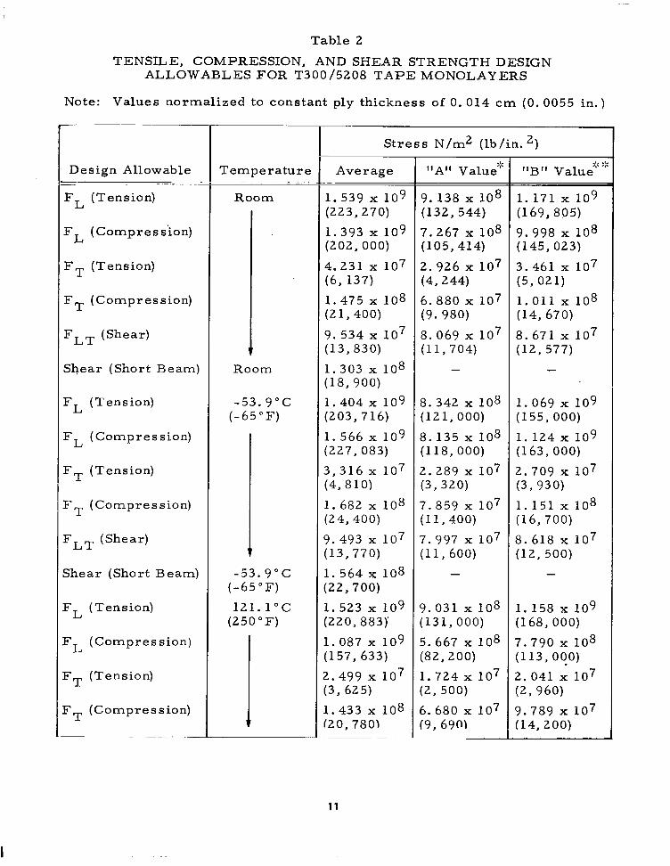
Table 2
TENSILE, COMPRESSION, AND SHEAR STRENGTH DESIGN ALLOWABLES FOR T300/5208 TAPE MONOLAYERS
Note: Values normalized to constant ply thickness of 0. 014 cm (0. 0055 in.)
Design Allowable - FL (Tension)
FL (Compress’ion)
FT (Tension)
FT (Compression)
FLT (Shear)
Shear (Short Beam)
FL (Tension)
FL (Compression)
FT (Tension)
FT (Compression)
FLT (Shear)
Shear (Short Beam)
FL (Tension)
FL (C ompression)
FT (Tension)
FT (Compression)
Temperature
Room
v Room
-53.9”C (-65°F)
-53.9”C (-65°F)
121.1”C (250°F)
Stress N/m2 (lb/in. 2, 1 Average
1.539 x 10⁹ (223,270)
1.393 x 10⁹ (202,000)
4.231 x 10⁷ (6, 137)
1.475 x 10⁸ (21,400)
9.534 x 10⁷ (13, 830)
1.303 x 10⁸ (18, 900)
1.404 x 10⁹ (203,716)
1.566 x 10⁹ (227, 083)
3,316 x lo7 (4,810)
1. 682 x 108 (24, 400)
3.493 x 10⁷ (13,770)
1. 564 x 108 :22,700)
I. 523 x 109 :220, 883)
1.087 x 10⁹ (157, 633)
t.499 x 107 :3, 625)
1.433 x 10⁸ ‘20, 780)
11
9.138 x lo8 (132, 544)
7.267 x 10⁸ (105,414)
2.926 x lo7 (4,244)
6.880 x 10⁷ (9.980)
8.069 x lo7 (11,704)
-
8.342 x 10⁸ (121,000)
8.135 x 10⁸ (118, 000)
2.289 x 10⁷ (3,320)
7.859 x lo7 (11,400)
7.997 x 10⁷ (11, 600)
-
3.031 x 10⁸ (131,000)
5.667 x 10⁸ (82,200)
1.724 x lo7 (2, 500)
6.680 x 10⁷ (9, 690)
::: “B” Value
:::
1.171 x 10⁹ (169,805)
9.998 x lo8 (145, 023)
3.461 x lo7 (5,021)
1.011 x 10⁸ (14, 670)
8. 671 x lo7 (12,577)
1.069 x 10⁹ (155,000)
1.124 x 10⁹ (163, 000)
2.709 x 10⁷ (3,930)
1.151 x 10⁸ (16,700)
8.618 x 10⁷ (12,500)
-
1.158 x 10⁹ (168,000)
7.790 x 10⁸ (113, oqo)
2.041 x 10⁷ (2, 960)
3.789 x lo7 (14,200)

Table 2 (Concluded)
TENSILE, COMPRESSION, AND SHEAR STRENGTH DESIGN ALLOWABLES FOR T300/5208 TAPE MONOLAYERS
(Note: Values normalized to constant ply thickness of 0. 014 cm (0. 0055 in.)
I Design Allowable
FLT (Shear)
Shear ‘(Short Beam)
Stress N/m2 (lb/in. 2,
9: Temperature Average “A” Value’
:;: :;: “B” Value
121.1 c (250 F) 6.308 x lo7 5.336 x lo7 5.736 x lo7 (9,150) (7,740) (8,320)
121.1 “C 7.997 x 10⁷ - - (250°F) (11, 600)
>:“A” value: A statistical value where 99% or greater of the samples will achieve such a strength with a 95% confidence level.
:$IIBfI value- . A statistical value where 90% or greater of the samples will achieve such a strength with a 95% confidence level.
Table 3
DESIGN VALUES FOR ELASTIC MODULUS
Note: (1) Values normalized to constant ply thickness = 0. 014 cm (0. 0055 in.) (2) T300 /5208 monolaver construction.
I== Temperature
Room
-53.9”C (-65°F)
12l.l”C (250°F)
T Tension Compression
EL EL
14.68 x lOlo 13.10 x lOlo (21.3 x 10⁶) (19.0 x 10⁶)
Tension
ET
1.09 x 1o1O (1.58 x lo6
14.89 x lOlo 14.27 x lOlo 1.21 x 10¹⁰ (21. 6 x 10⁶) 20.7 x 10⁶) (1.76 x 10⁶)
15.03 x lOlo 9.38 x 101’ (21.8 x 10⁶) (13.6 x 10⁶)
0.75 x 10¹⁰ (1.09 x 10⁶)
Modulus N/m2 (lb/in. 2,
Compression Shear
ET GLT
1
1.30 x lOlO (1.89 x 10⁶)
1.22 x 10¹⁰ (1.77 x 10⁶)
0.79 x 10¹⁰ (1.15 x 10⁶)
0.64 x lOlo (0.93 x 10⁶)
0.81 x 10⁶ (1.17 x 10⁶)
0.56 x lOlo (0.84 x 10⁶)
12

Table 4
DESIGN VALUES OF FAILURE STRAIN AND POISSON’S RATIO (T300/5208 monolayer construction)
Failure Strain
90-Deg Zero-Deg Direction Direction Poisson’s Ratio, pLT
Temperature Tension Compression Tension Tension Compression
Room 0.011 0.0086 0.0036 0.377 0.380
-53.9”C 0.0093 0.0078 0.002 1 0.386 0.373 (-65°F)
12l.l”C 0.0099 0.0097 0.0032 0.379 0.400 (250” F)
Subelement panel tests, described in Section 3, produced only one modifica-
tion to the original shell wall design. Four plies of reinforcing zero-degree
plies were originally used in the corrugation crowns, that number being
increased to five plies after initial compression tests with the first two
0.6 lm long panels. Thickness measurements of the first two test panels
showed the average cured ply thickness to be lower than the average thick-
ness derived from the data base, thus resulting in local buckling at lower
load intensities than the design goal of 1, 576 N/cm. The five plies of longi-
tudinals resulted in a computed cylinder weight increase of approximately
5% when compared to the original design. No other changes were required
in the original cylinder design.
The overall design approach thus used a shell wall made of three flat panels
that were formed to the required cylindrical shape on assembly and joined at
three longitudinal seams. Similarly, the four ring stiffeners were each made
in three segments and joined with splice caps during assembly. The selected
approach was chosen to simplify fabrication, lower costs, and permit achieve-
ment of required cylinder tolerances.
2.2 SHELL BUCKLING ANALYSIS AND RING-STIFFENER DESIGN
A primary objective of the design effort was to achieve a test cylinder that
would fail in general instability buckling. To achieve this goal, the corru-
gated shell wall configuration was designed to provide adequate margins of
13

I
safety in local element buckling and shell buckling between rings. Simul-
taneously, the spacing and stiffness characteristics of the stiffening rings
were adjusted to allow a minimum design margin in the general instability
buckling mode of failure.
Results of analytical failure predictions, summarized in Figure 3, show the
effects of variations in ring bending stiffness on the load intensity that causes
general instability failure in the shell. Load intensities that cause local
buckling of corrugation elements and buckling between rings are unaffected
by ring stiffness and are therefore shown as constant values. As shown in
Figure 3, the load causing failure by general instability increases with
increasing ring stiffness until another failure mode’becomes critical. The
design ring bending stiffness parameter, EIR, was chosen as 69.7 N-m2
(2.43 x lo4 lb-in. 2, t o meet the design load intensity of 1, 576 N/cm with a
small margin of safety, A closed hat section (Figure 2) was selected for the
ring-stiffener cross section to provide adequate torsional stiffness as well
as the desired bending stiffness.
L L E 6 RING BENDING STIFFNESS, EIR x 1O-4 (LBF-IN21
L I I I I I I 30 40 50 60 70 a0 90
RING BENDING STIFFNESS, EIR (N-m2)
Figure 3. Summary of Critical Shell Compressive Lotid as a Function of Ring Bending Stiffness
14

Primary criteria for sizing the intermediate ring stiffeners were: (1) the
bending stiffness of the ring cross section would meet the value of EIR
determined in NASA preliminary studies, and (2) the extensional and torsional
stiffness characteristics would meet or exceed the preliminary study values.
Ring stiffness properties defined in preliminary analyses were:
EIR = 69.7 N-m2 (2.43 x lo4 lb-in.2)
EAR = 19.4 x lo5 N (4.37 x IO5 lb)
GJR = 44. 5 N-m2 (1.55 x lo4 lb-in.2)
The selected design for the intermediate ring stiffeners, shown in Figure 4,
consists of a hat section adhesively bonded to a base plate. The closed
section is required to meet the torsional stiffness requirements defined in
preliminary design studies.
NOTE: 1. ALL MATERIAL T300/5208 PREPREG TAPE
2. DIMENSIONS GIVEN IN cm (IN.)
I- 5.72 (2.25)
-I
t
:iz 2,
I
t 0.0623 (0.0324)
.4 PLIES 145 DEG. 0.055 cm 10.022 IN.) THICK
-2 PLIES ZERO-DEGREE, 0.026 cm (0.0104 IN.) THICK
A4 PLIES *45 DEG. 0.056 cm (0.022 IN.) THICK
Figun 4. RinqStiffmar Cross So&on
15

Also, the ring stiffeners were designed to meet the attachment loads as shown
in Table 1. Other criteria considered in designing the ring stiffeners were:
(1) the design would minimize the possibility of warping or the introduction
of severe residual strains during cure, and (2) the design would lend itself to
ease of fabrication with low cost and minimum weight. Positive margins of
safety were computed for all design load conditions for the ring stiffeners,
and those calculations were subsequently substantiated in tests of the
2.54m (100 in. ) panels.
The use of clips to attach the rings to the inner corrugation crowns was
considered in initial design studies. However , previous tests (Reference 6)
have shown such attachments do not increase the cylinder’s resistance to
general instability buckling. Thus, ring-to-shell attachment clips posed the
disadvantages of increased weight and cost without providing any significant
increase in shell strength. For those reasons, the simple attachment of
the stiffening rings at points where the rings mate with the external corru-
gation crowns was chosen.
2.3 DETAILED DESIGN OF SHELL
Special design attention was required for joints in three areas of the cylinder.
The first such area, attachment of the cylinder ends to the steel test rings,
required a joint with sufficient strength to satisfactorily introduce the loads
into the shell wall and sufficient stiffness to prevent local buckling of the
graphite-epoxy corrugated shell from stress concentrations near the attach-
ment areas. A bolted joint design (Figure 2) was selected that used three
aluminum rings made from stretch-formed extruded angles. Each ring was
made in three 120-deg segments which were joined together on assembly.
The two rings that mated with the corrugated wall had scalloped fingers to
pick up the corrugation crowns with two shear bolts at each crown position.
The scalloped fingers on the aluminum rings permitted access to the bolts
from both sides of the joint because the inner and outer corrugation crowns
form an alternating pattern around the circumference of the wall. Stepped
graphite-epoxy doublers reinforced the corrugation crowns near the shell
ends to provide added stiffness and to give adequate strength at the bolt
16
attachment area. The attachment design featured close-tolerance bolts of
0. 953-cm (0. 375 in.) diameter, placed in attachment holes that were match-
drilled and reamed on assembly.
A second area requiring special design attention was found in the longitudinal
joints along the length of the shell wall where the three corrugated panels were
joined to form the completed cylindrical shell. The joint area was required
to have adequate strength and also elongation (EA) stiffness characteristics
equal to the basic wall, so that buckling characteristics of the wall remained
constant. An overlapping joint was designed in which two crowns were over-
lapped, adhesively bonded, and riveted with blind rivets. To maintain stiff-
ness equal to other corrugation crowns, the five plies of reinforcing T300/
5208 zero-degree strips were replaced with three 143/5208 glass cloth strips
having significantly lower modulus. Thus, the thicker area at the overlapping
joint was offset by low-modulus reinforcing strips to maintain constant EA
characteristics.
Criteria for sizing the splice were (1) the extensional stiffness of the splice
would not exceed the value for the shell wall but would match the stiffness of
the shell wall as closely as possible, (2) the riveted connections would not
result in local interfastener buckling, (3) the splice method would not
affect the straightness of the shell wall, and (4) local buckling of the spliced
segment would equal or exceed that for the shell wall.
Several combinations of materials and plies were considered in the prelimi-
nary design, and the selected combination was one that replaced the five
T300/5200 zero-degree plies with three plies of E-glass longitudinals (see
Figure 5). The splice area extensional stiffness obtained with such a design
was one that most nearly matched the basic shell wall extensional stiffness.
Because local buckling is a function of both local stiffness and local wall
thickness, the local buckling allowable in the splice area was significantly
higher than that of the basic corrugation crown due to the approximately equal
stiffness characteristics combined with the greater thickness in the splice
area.
17

I
I 3 a*n em EG LASS - .- - - -. .
- (‘1 AR7 Ih . . .._. ..J.J--- I
3 PLIES,
/- 0.076 cm IO.030 IN.)
14315206 E-GLASS (3 PLIES)
*45DEG PLIES 4 PLIES, 0.056 cm (0.022 IN. THICK)
VIEW A
Figure 5. Shell Wall Longitudinal Splice Design
A third area requiring special attention was the attachment of the external
stiffening rings to the shell wall. Design loads for the ring attachments were
developed based on computed buckling patterns of the shell. The ring attach-
ment was designed to use blind rivets and an adhesive bond at each position
where the rings cross the external crown areas: the design was subsequently
proven satisfactory in compression tests of two 2. 54m (100 in. ) test panels.
From initial design studies, the weight of the basic corrugated shell wall was
computed to be 0. 0143 kg/m2 (0. 34 lbm/ft2). With allowance for joints and
ring stiffeners, the shell wall weight was estimated as 0. 0156 kg/m2
(0. 37 lbm/ft’). To compare those weights with shell wall weights of aluminum
cylindrical shells, Figure 6 was plotted to show the weight parameter, W/AR,
as a function of the shell load intensity parameter, N,/R. For the shell
loading of interest (1576 N/ cm) and a shell radius of 1. 524m (60 in.), the
graphite-epoxy corrugated shell shows a weight saving of approximately 23%
over a similar aluminum shell.
2.4 DESIGN DEVELOPMENT TESTS
Development tests were conducted with sample parts or coupons for three
purposes: (1) to verify the design characteristics of the attachment area at
the cylinder ends, (2) to confirm the stiffness characteristics of the stiffening
ring design, and (3) to determine the tensile, flexure, and compression char-
acteristics of samples made with the same layup as that used in the corrugation
crown areas. 18

10-3 1y------- 1
_ LEGEND 0 ALUMINUM SKIN/STRINGER. RINGS
- 0 CORRUGATED ALUMINUM, INTERNAL RINGS A CORRUGATED ALUMINUM. EXTERNAL RINGS
0 CORRUGATEDGRAPHITE-EPOXY, EXTERNAL RINGS (ANALYSIS) -
20
10
a
6
1
0.8 0.6
0.4
-
- ALUMINUM CORRUGATED CYLINDER, EXTERNAL
-
: t 10-6 1 1 I I I I I I 1 1 2 2 4 4 6 6 a a 10 10 20 20 40 40 60 60 80 80 100 100
NJR (L6F/IN.21 NJR (L6F/IN.21
I._. 1 I._. 1 IA II IA II I I I I I I I I I I 106 106 106 106 10’ 10’
N,/R (N/n?) N,/R (N/n?)
Figure 6. Structural Efficiencies of Cylindrical Shells in Compression
2. 4. 1 Cylinder End Attachment Tests
A typical bolted joint sample used in tests to evaluate the attachment of the
adapter rings to the cylinder ends is shown in Figure 7. The maximum design
load required to be introduced at each corrugation crown is 8,985N (2,020 lbf),
based on a maximum bending load intensity of 1, 576 N/cm (900 lbf/in) along the
circumference of the cylinder and a crown spacing of 5.70 cm. Three bolted
joint samples with four zero-degree reinforcing plies were initially tested in
tension, two having both bolts in place at each end and one having one bolt
removed at one end of the sample. Test results, presented in Table 5,
show the reinforced corrugation samples sustained tension loads of 2. 291 x
104N (5,150 lbf) and 2.202 x 10⁴N (4,950 lbf) when both bolts were used. With
only one bolt acting, the load at failure was 1. 913 x 104N (4, 300 lbf). Thus,
more than twice the design load of 8, 985 N was carried with only one bolt
acting, indicatiilg a substantial margin of safety. Two additional samples
were tested after changing from four to five reinforcing plies in the crowns.
19

-,_.-----.,-.. - _. .._...__ ..-.--.--_-.-- --... .--.- -..-- --.. .-. -..-..-. .._._.. ----._-- I
Figure 7. Bolted Joint Test Sample Simulating Shell End Attachment
With the additional reinforcing ply, the fourth and fifth test samples failed at
2. 313 x 104N (5, 200 lbf) and 2. 580 x 104N (5, 800 lbf), respectively. Thus, ‘a
high margin of safety in tension loading was demonstrated by the bolted joint
samples simulating the adapter ring attachment to the cylinder wall.
Figures 8 and 9 show typical failures in the bolted joint samples. Figure 8
shows the failure in sample 1 (Table 5) in which tensile failure of the rein-
forced graphite-epoxy area at the inner bolt hole was the mode of failure.
The bearing stress failure of sample 2 (Table 5) is shown in Figure 9, where
the sample was tested with only the outer bolt in place at one end of the
sample.
2.4.2 Ring-Stiffener Tests
Ring-stiffener tests were conducted to evaluate ring bending stiffness as a
function of stiffener depth. Such tests were deemed necessary because of the
significant change in cylinder general instability failure load that occurs with
changes in the ring-stiffener bending stiffness, EIR (Figure 3). Four simu-
lated ring- stiffener segments of three diffenz nt depths were fabricated for
20

Table 5
BOLTED JOINT TEST RESULT,!
1 r Failure Load
Failure Stress Test Sample Failure Location and Type
q -
Inner Bolt Hole, Tension Failure No. 1
(All bolts in position)
3. 23x108N/m2" (46, 900 psi)
22,910 N (5,150 lb)
Outer Bolt Hole, Bearing Failure 7. 67x1 08N/m2 (111,200 psi)
No. 2 (One bolt
removed)
19,130N (4,300 lb) Bolt Removed
No. 3 (All bolts in
position) 5. 52x198N/m2 (80, 000 psi)
22,020N (4,950 lb)
Center Area, Tension Failure at End of Doublers
0. 652x108N/m2 (9,455 psi) (shear)
Tensile Shear Failure at Bolt Holes No. 4
(All bolts in position)
23,130N (5,200 lb)
Tensile Shear Failure at Bolt Holes
No. 5 (All bolts in Position) I I 0. 727x108N/m2
(10,545 psi) (shear)
25,800N (5, 800 lb)
Net area stress at bolt hole. I J

Figure 8. Tensile Failure at Inner Bolt Hole
Figure 9. Bearing Failure at Bolt Hole
22

the bending tests, each segment being 0. 61m (24 in. ) long. Two hats were
designed to a depth to provide the nominally required EIB of 69.7 N-m2
(2.43 x lo4 lb-in2). A third was designed to a depth computed to give a
55% increase in the EIR value; the fourth section was computed to decrease
the nominal EIB value by 40%.
The hat portions of the ring-stiffener test samples were laid up and cured
as a continuous sheet and then cut into separate stiffeners after being bonded
to the separately made base plate. Bonding was accomplished with EA-9309
epoxy adhesive, the parts being held together under vacuum-bag pressure for
24 hours. Figure 10 shows the cured hat portions of the simulated stiffener
segments after their removal from the male aluminum torjl used for layup
and cure. Figure 11 shows three of the simulated stiffeners ready for testing.
A four-point loading system was used to apply bending moments to each
stiffener and deflections were measured as a function of load. The slope of
the deflection versus load curve was then used to determine the effective I+
Figure 10. RinpStiffenrr Hat Test Samples Removed from Mold
23

Figure 11. RintStiffener Test Samples
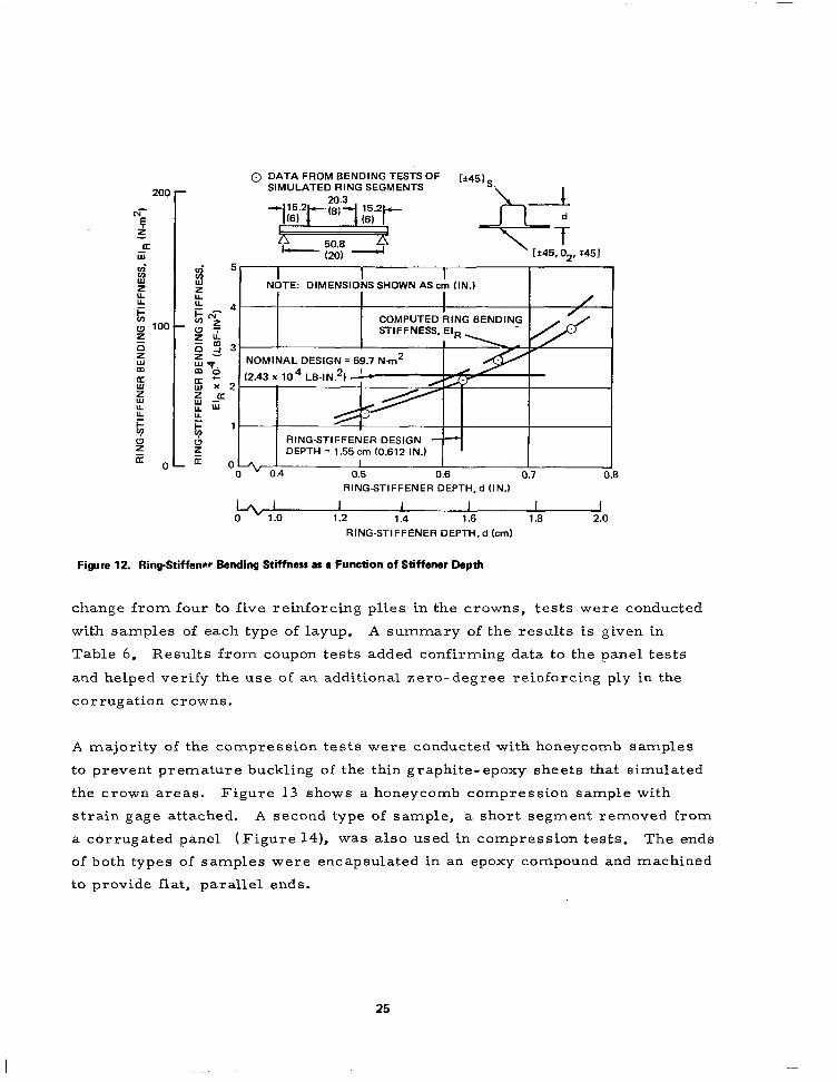
for each test ring segment. Figure 12 shows results of the ring-stiffener
bending tests and indicates satisfactory bending stiffness characteristics {or
stiffeners with a nominal design depth of 1. 55 cm (0. 612 in.)
2. 4. 3 Material Property Tests
Because initial design and analysis of the cylinder was based upon data
obtained from monolayer (unidirectional) T300 /5208 samples, tests of samples
having the actual layup of the corrugation cr.own areas were conducted to
provide coupon test data to supplement the panel test results. Tests were
conducted to determine typical tensile strength and Young’s modulus, flexural
strength and modulus values, and elastic modulus under compressive loading.
A portion of the samples were taken from extra crown areas at the sides of
the 0.61m test panels, the mold for those panels having been made with suffi-
cient width to accommodate an extra crown layup at both sides of the panel.
A majority of the tensile and flexure specimens were obtained from panel
trim material, with some being made from flat sheets laid up and cured
using the same process as that used to fabricate the panels. Because of the
24
0 DATA FROM BENDING TESTS OF SIMULATED RING SEGMENTS
STIFFNESS, El
DEPTH = 1.55 cm (0.612 IN.1 I
s 0.4 I I I I
0.5 0.6 0.1 0.8
I 1 .o
RINGSTIFFENER DEPTH.d (IN.)
I I I I I 1.2 1.4 1.6 1.8 2.0
RING-STIFFENER DEPTH,d km)
Figure 12. RingStiffenrr Bending Stiffness as (I Function of Stiffener Depth
change from four to five reinforcing plies in the crowns, tests were conducted
with samples of each type of layup. A summary of the results is given in
Table 6. Results from coupon tests added confirming data to the panel tests
and helped verify the use of an additional zero-degree reinforcing ply in the
corrugation crowns.
A majority of the compression tests were conducted with honeycomb samples
to prevent premature buckling of the thin graphite-epoxy sheets that simulated
the crown areas. Figure 13 shows a honeycomb compression sample with
strain gage attached. A second type of sample, a short segment removed from
a corrugated panel (F g i ure 14), was also used in compression tests. The ends
of both types of samples were encapsulated in an epoxy compound and machined
to provide flat, parallel ends.
25
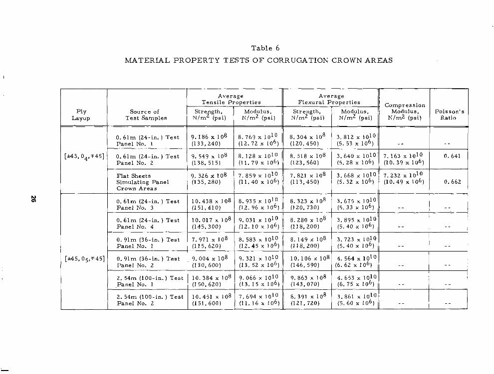
Table 6
MATERIAL PROPERTY TESTS OF CORRUGATION CROWN AREAS
Source of
0. 6lm (24-in. ) Test 10.017 x 10
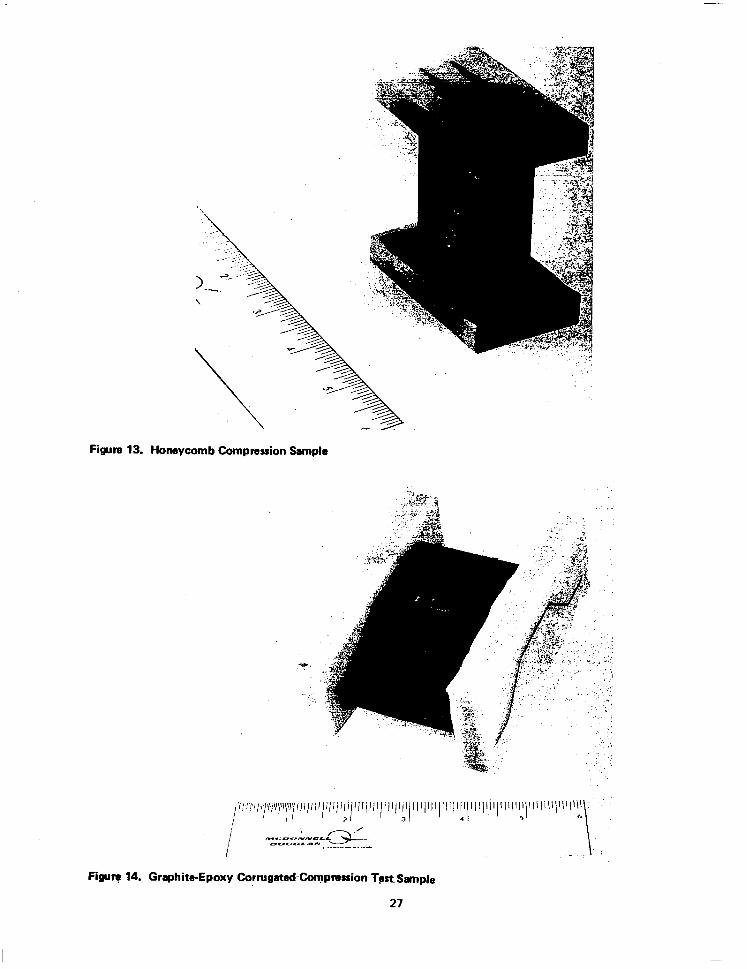
Figure 13. Honeycomb Compression Sample

.__. ..-... .-
Section 3
SUBELEMENT TEST PANELS
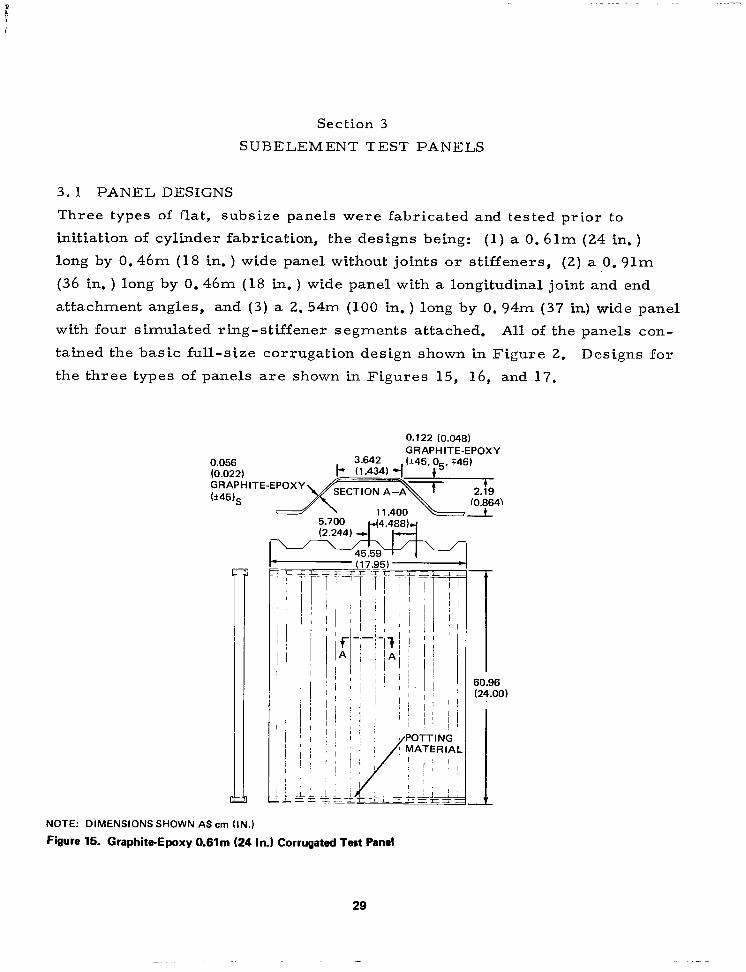
3.1 PANEL DESIGNS
Three types of flat, subsize panels were fabricated and tested prior to
initiation of cylinder fabrication, the designs being: (1) a 0.61m (24 in. )
long by 0.46m (18 in. ) wide panel without joints or stiffeners, (2) a 0. 91m
(36 in. ) long by 0.46m (18 in. ) wide panel with a longitudinal joint and end
attachment angles, and (3) a 2. 54m (100 in. ) long by 0. 94m (37 in) wide panel
with four simulated ring-stiffener segments attached. All of the panels con-
tained the basic full-size corrugation design shown in Figure 2. Designs for
the three types of panels are shown in Figures 15, 16, and 17.
0.122 (0.048) GRAPHITE-EPOXY
0.056 (0.022)
NOTE: DIMENSIONS SHOWN AS cm (IN.)
Figure 15. Graphite-Epoxy 0.61m (24 In.) Corrugated Test Panel

11.400 (4.488)
t 3.642 (1.434)
GRAPHITE-EPOXY b451,
14315208 E-G LASS,
GRAPHITE-EPOXY 120 GLASS CLOTH
NAS 1738 RIVET WITH SEALAN
SECTION B-B SECTION A-A
NOTE: DIMENSIONS SHOWN AS CM (IN.1
91.44 (36;O
Figure 16. GraphiteEpoxy 0.91m (36-In.) Test Panel

SIMULATED CORRUGATED PANEL
SECTION B-B
RING T T--
I:-----zrIi - 1---- - -- -
‘I-- --t .A- -__ ~- -_-
II--II ~- I--
4 1 ? i------- +4--- ___- --- ,--~, - -~ --- _- - --- II-.- - __ --__ ~- --A- ---
--~ I-~ -~ - - -- -- - 11
- --- t + + + +
I-1 - - -+I+ -- -- -- - --
I I I 60.96 60.96
(14.00) (24.001 (24.00)
~~~~ i
+
,~
POTTING MATERIAL
SECTION A-A (ti5)s
NOTE: DIMENSIONS SHOWN AS CM (IN.1
Figun 17. GraphiteEpoxy 2.54m (1~In.) Long Test Panel
The smallest type of test panel (Figure 15) was 0.61m long with a width of
0.46m. The panel was designed to provide an assessment of the local buck-
ling capability of the basic shell wall corrugation configuration.
The second type of test panel (Figure 16), 0.91m by 0.46m, was designed to
evaluate the longitudinal joint areas where the three corrugated panels are
spliced to form the cylinder and to test the end attach areas where the bend-
ing moment is introduced into the shell wall.
A third type of test panel, shown in Figure 17, was 2. 54m (100 in. ) long and
0. 94m (37 in. ) wide. It was designed to evaluate the ring-stiffener attach-
ment to the corrugated wall and to determine buckling characteristics of a
panel approximating the full length of the cylinder.
3.2 PANEL FABRICATION AND NONDESTRUCTIVE TESTS
All test panels, as well as the full-size cylinder panels, were laid up and
cured on flat aluminum molds machined to the proper corrugated cross-
sectional configuration. All of the subsize test panels were sufficiently small
in panel width that allowance for tool expansion was not required in designing
the molds. However, the full-size cylinder panels with a nominal width of
3. 23m (127 in. ) required allowance for thermal expansion of the aluminum
mold at the cure temperature of 177°C (350”F), and the corrugated cross
section was therefore adjusted to a slightly smaller corrugation pitch dimen-
sion than the finished part. All panels were made with excess length and
then trimmed to size after cure, a procedure that eliminated the necessity
of tool dimension changes for expansion along the length of the corrugations.
To reduce costs, a single mold was used to fabricate both the 0. 61m panels
and the 0. 91m test panels. The mold for those two panels was machined
from 6061 aluminum plate. However, the mold for the 2. 54m (100 in. ) long
test panels and the mold for the full-size panels were machined from cast
aluminum plates. This approach was taken to avoid welded seams in the full-
size mold or, alternately, the possible expense of a special run of overwidth
606 1 aluminum plate material.
32
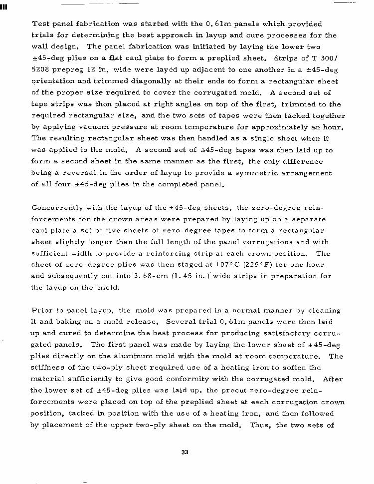
Test panel fabrication was started with the 0.61m panels which provided
trials for determining the best approach in layup and cure processes for the
wall design. The panel fabrication was initiated by laying the lower two
-+45-deg plies on a flat caul plate to form a preplied sheet. Strips of T 300/
5208 prepreg 12 in. wide were layed up adjacent to one another in a &45-deg
orientation and trimmed diagonally at their ends to form a rectangular sheet
of the proper size required to cover the corrugated mold. A second set of
tape strips was then placed at right angles on top of the first, trimmed to the
required rectangular s ize, and the two sets of tapes were then tacked, together
by applying vacuum pressure at room temperature for approximately an hour.
The resulting rectangular sheet was then handled as a single sheet when it
was applied to the mold. A second set of &45-deg tapes was then laid up to
form a second sheet in the same manner as the first, the only difference
being a reversal in the order of layup to provide a symmetric arrangement
of all four &45-deg plies in the completed panel.
Concurrently with the layup of the *45-deg sheets, the zero-degree rein-
forcements for the crown areas were prepared by laying up on a separate
caul plate a set of five sheets of zero-degree tapes to form a rectangular
sheet slightly longer than the full length of the panel corrugations and with
sufficient width to provide a reinforcing strip at each crown position. The
sheet of zero-degree plies was then staged at 107°C (225°F) for one hour
and subsequently cut into 3. 68-cm (1. 45 in. )‘wide strips in preparation for
the layup on the mold.
Prior to panel layup, the mold was prepared in a normal manner by cleaning
it and baking on a mold release, Several trial 0. 61m panels were then laid
up and cured to determine the best process for producing satisfactory corru-
gated panels. The first panel was made by laying the lower sheet of %45-deg
plies directly on the aluminum mold with the mold at room temperature. The
stiffness of the two-ply sheet required use of a heating iron to soften the
material sufficiently to give good conformity with the corrugated mold. After
the lower set of &45-deg plies was laid up, the precut zero-degree rein-
forcements were placed on top of the preplied sheet at each corrugation crown
position, tacked in position with the use of a heating iron, and then followed
by placement of the upper two-ply sheet on the mold. Thus, the two sets of
33

&45-deg sheets provided continuity throughout the corrugated panel and sand-
wiched the zero-degree reinforcements at the crown areas. The internal
location of the zero plies provided a superior design arrangement ,compared
to externally located reinforcements since the latter arrangement often leads
to separation of the zero plies under compression loads. After the graphite-
epoxy material was in place, a layer of porous Armalon was used as a sepa-
rator and one layer of Mochburg was used as a bleeder. For the 0.61m
panels, nylon film bagging was used and the parts were autoclave-cured at
177oC (350°F) for 3 hours at 6. 894 x lo5 N/m2 (100 psi) pressure.
The initial process was generally satisfactory but produced resin-rich areas
at the corners of the lower corrugation crowns located in the “valleys” on
the mold. Subsequent tests of a panel with resin-rich areas indicated that
structural performance was not impaired by such areas: however, a process
change was made to reduce the excess resin in local areas. The resin- rich
areas were largely eliminated by using thinner bleeder material and placing
one layer of bleeder between the mold and the graphite-epoxy plies as well
as one layer on top of the layup. To provide satisfactory adherence of the
bleeder to the mold, a volatile noncontaminating light adhesive was sprayed
on the mold surface. The same procedure was used to tack the Armalon
separator to the bleeder.
The basic panel layup that was developed during fabrication trials with the
0.6lm panels and used throughout the remainder of the program consisted of
(1) a thin layer of bleeder placed on the mold, (2) a sheet of porous Armalon
on top of the bleeder, (3) a lower sheet of &45-deg plies, (4) strips of zero-
degree reinforcing plies at each corrugation crown, (5) a top sheet of &45-
deg plies, (6) a second sheet of porous Armalon, and (7) an upper layer of
bleeder. A cured 0. 61m panel is shown in Figure 18 with the aluminum mold,
The cured 0.61m panels were trimmed to the proper width and each end was
then potted in an aluminum-filled epoxy compound to stabilize the ends and
prevent local failure when the panels were tested in axial compression. The
potted ends of the panels were then machined to provide flat, parallel sur-
faces that were perpendicular to the longitudinal axis of the panels to be mated
with the loading surfaces of the test machine.
34

Figure 18. Corrugated Test Panel and Aluminum Mold
Prior to layup and cure of the 0. 91m long panels, the aluminum mold was
reworked to incorporate local cavities for panel end doublers and one crown
area of the mold was remilled to provide for an overlap type panel-to-panel
joint which was planned for the full size cylinder. Also, a reusable silicone
rubber autoclave bag was prepared to evaluate such a concept for the full-
size cylinder. The cured bag is shown in Figures 19 and 20. Use of the
silicone rubber bag was entirely successful in fabricating the 0. 91m panels,
and that type of bag was therefore selected for use in making the full-size
panels.
The 0.91m long panels were laid up and cured using the same basic tech-
nique as developed with the 0.61m panels. To provide evaluation of the end
attachment areas, doublers made from T300/5208 bidirectional woven cloth
were placed at the ends of each corrugation crown and cocured with the basic
panels. Two thicknesses of cloth were used on both sides of each corruga-
tion crown at the panel ends (Figure 16). Ln addition, the cured panel was
cut longitudinally into two pieces and then rejoined with a riveted and adhe-
35

Figure 19. Silicone Rubber Bag on Corrugated Mold
Figure 20. Rubber Bag Being Removed from Mold
36
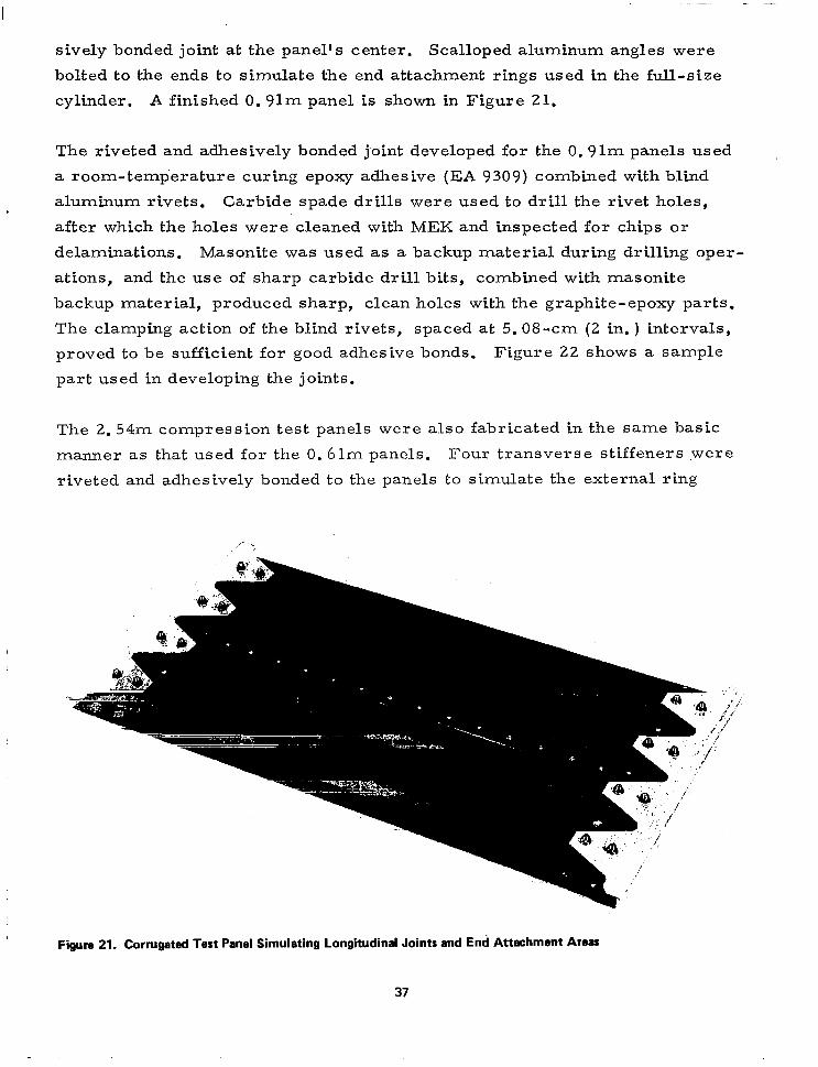
sively bonded joint at the panel’s center. Scalloped aluminum angles were
bolted to the ends to simulate the end attachment rings used in the full-size
cylinder. A finished 0.91m panel is shown in Figure 21.
The riveted and adhesively bonded joint developed for the 0. 91m panels used
a room-temperature curing epoxy adhesive (EA 9309) combined with blind
aluminum rivets. Carbide spade drills were used to drill the rivet holes,
after which the holes were cleaned with MEK and inspected for chips or
delaminations. Masonite was used as a backup material during drilling oper-
ations, and the use of sharp carbide drill bits, combined with masonite
backup material, produced sharp, clean holes with the graphite-epoxy parts.
The clamping action of the blind rivets, spaced at 5.08-cm (2 in, ) intervals,
proved to be sufficient for good adhesive bonds. Figure 22 shows a sample
part used in developing the joints.
The 2. 54m compression test panels were also fabricated in the same basic
manner as that used for the 0.61m panels. Four transverse stiffeners .were
riveted and adhesively bonded to the panels to simulate the external ring
Figure 21. Corrugated Test Panel Simulating Longitudind Joints and Enh Attachment Areas
37

\
Figure 22. Segment of Bonded and Riveted Longitudinal Joint Sample
stiffeners attached to the full-size cylinder. As with the 0. 61m panels, the
ends of the 2.54m panels were encased with an aluminum-filled epoxy com-
pound and machined to provide flat surfaces that mated with the loading heads
in the test machine. Figure 23 shows a completed 2.54m test panel.
The basic process developed in fabricating the 0.61m panels was used for
layup and cure of all subsequent test panels and the full-size cylinder panels.
Because of their substantial masses and consequent large heat sink effects,
the molds for the 2. 54m test panels and the full-size cylinder panels pre-
vented effective use of small heating irons to warm the &45-d&g preplied
sheets of graphite-epoxy, To provide the necessary heat and the resulting
pliability in the graphite-epoxy sheets, the larger molds were heated directly
with hot air to approximately 37.8OC (lOOoF). That procedure proved suc-
cessful in heating the graphite-epoxy plies sufficiently to permit good con-
formity of the rt45-deg sheets to the mold contour. Also, the bleeder mate-
rial was changed to a 120-style fabric for the larger panels in order to obtain
better conformity to the molds.
38

Figure 23. Subelement Test Panel 2.54m (100 In.) Long
Nondestructi;ve tests using ultrasonic C-scan techniques were conducted to
evaluate the subelement panels for internal defects. A sample corrugation
10. 26 cm (4 in. ) long was constructed and scanned ultrasonically initially to
detect flaws. None were detected and the sample was purposely defected to
provide a baseline C-scan chart to compare with those generated by scanning
the corrugated test panels. The test setup is shown in Figure 24, in which
the part was placed on a clear plastic reflector plate immersed in a tank of
water. Crown areas were inspected by passing sound waves at 5 MHz through
the panel crowns with the waves being reflected from the plastic plate back
through the crown. A flat ~-MHZ Automation Industries type SIL transducer
0. 953 cm (0. 375 in. ) in diameter was used. After scanning the panel in one
position, it was inverted to check the remaining crown areas. C-scan traces
of the small, purposely defected panel are shown in Figure 25, and the defec-
tive area is noted.
A typical chart from scanning the crown areas of a 0.61m panel is shown in
Figure 26. All of the panels tested by ultrasonic C-scan techniques were
39

I I TRANSDUCER
GRAPHITE-EPOXY
I, t
CORRUGATED SOUND PATH PANEL
7 “\ PLASTIC REFLECTOR PLATE BOTTOM OF TANK
Figure 24. Ultrasonic CScan Test Arrangement
judged to have no delaminations or significant internal defects. Small anom-
alies in the C-scan charts were judged from experience with similar compo-
site parts to be caused by local variations in fiber spacing or resin content
within the panel layup. The latter estimate was substantiated by photomicro-
graphs made of samples taken from a panel trim area. The photomicro-
graphs, shown in Figure 27, showed a minimum void content and indicated
no delaminations in resin areas between the &45-deg plies and between the
inner 45-deg ply and the zero-degree plies. No distinct separation of the
zero-degree plies could be detected because of the nesting effect that occurs
when they are laid up. Some areas between the +45-deg plies had higher -
resin content than others, and thus tended to confirm the assessment from
C-scan tests that small anomalies were caused by some non-uniformity in
resin throughout the layup. The differences in resin content observed in the
photomicrographs of the samples examined were normal for the type of lami- .’ . nate construction used.
40

/ UNDAMAGED CROWN
I DELAMINATED AREA
~~
-. Y : --= s z = -z --- - --A= - =r
-. -2z 1= -. c= =
-= - T=T - = - =
!
-- WI
- _ -7 - --
GE- -.
-. = --. -- C-z = c - -- - =- -z = m =---z-z= =- = -- I- -- = -- -- =- --
z I- = T= = L = = = = = =. = = = ZZ = Z = = = = = = - = - 5 = = = = = - Z===
-- z- -- E -
- =r -. - =
= - Z
-- --
- -=
= .- .- - = .-- =
e-E ZP -= C -z -- - = E .-Z
--E - f=
.- -- .--h--Z --- .- .=-= -.-- -
E r -- -= C z =
.‘-zz= .BZ
e-z Z z*- - -77
-GOOD I DEFECTIVE
1 / HOLD DOWN BARS
Figun 25. Ultrasonic C-Scm Truer of Puq~dy Dam@ Corrwtd SrmPl@

.- i - ---. --. ..- _ ..-.. - .-.-. - ..__. I

A. VIEW OF SECTION PARALLEL TO ZERO-DEGREE Fl6ERS
8. VIEW OF SECTION NORMAL TO ZERO-DEGREE FIBERS
Both the ultasonic C-scan tests and the photomicrographic evaluations indi-
ca ted that no significant imperfections were evident in the test panels.
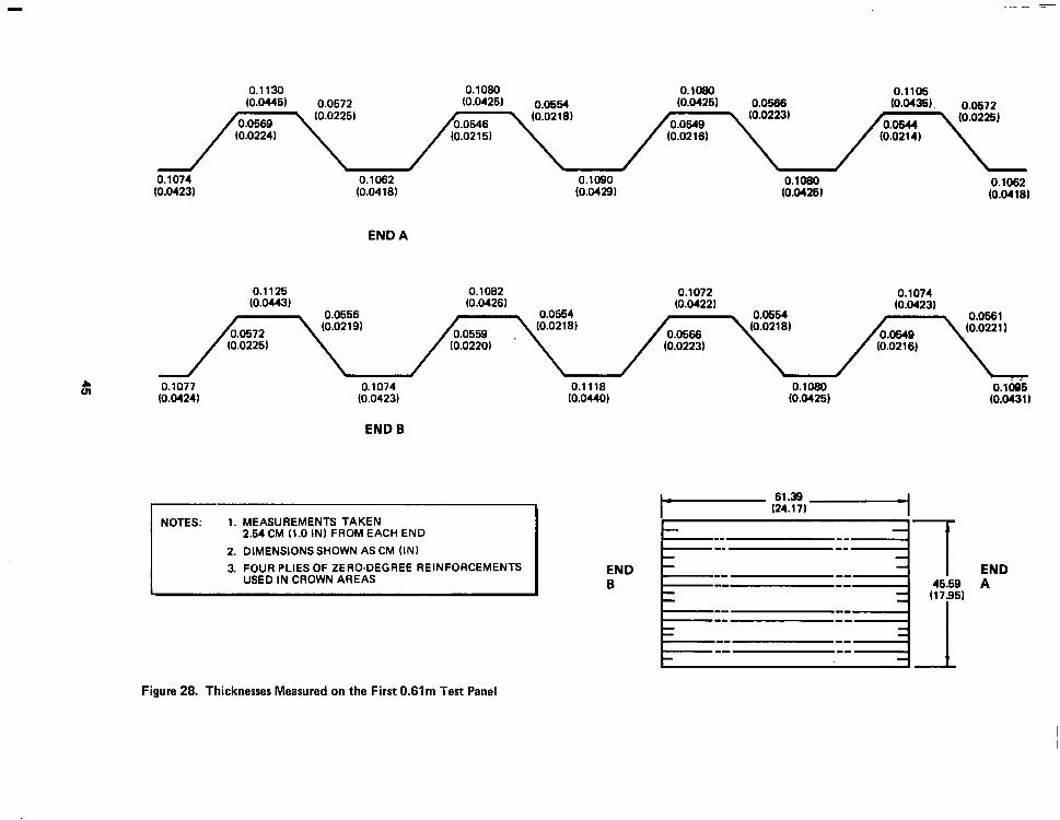
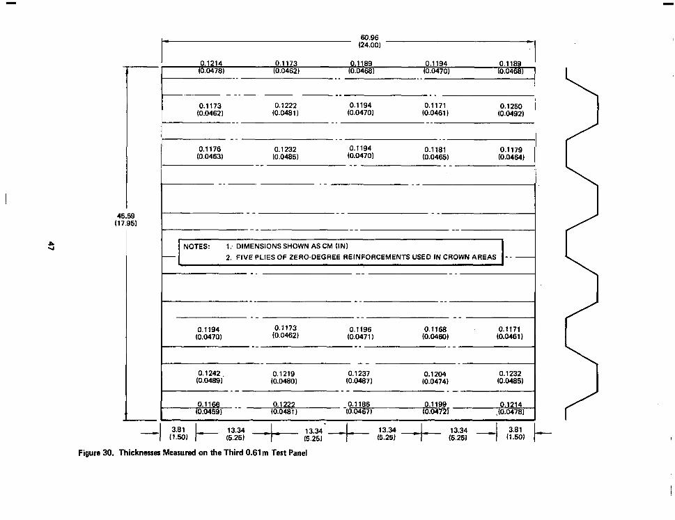
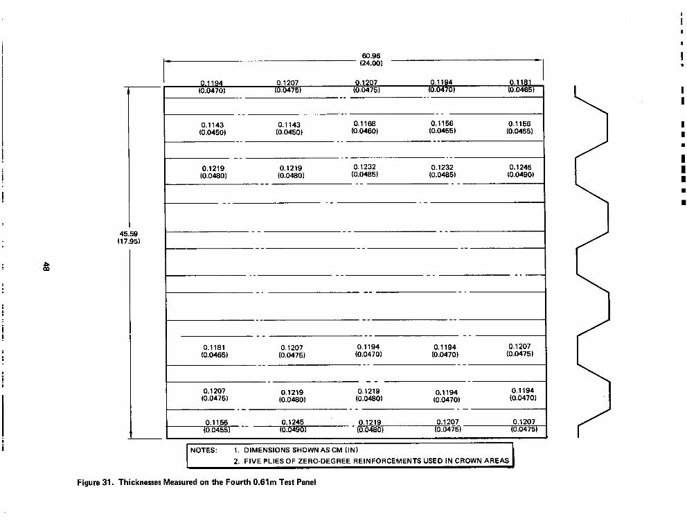
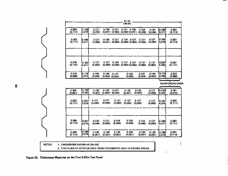
Thickness measurements were also made at a number of points on the test
panels, and such measurements were used in correlating results from local
buckling tests with analytical predictions. Panel test results are described
in the following subsection, and Figures 28 through’35 present thicknesses of
the subelement test panels.
3.3 PANEL TEST RESULTS
Compression tests were conducted with four 0. 61m panels to evaluate local
buckling characteristics of the corrugation and correlate test results with
the preliminary analysis. Initial tests, conducted with two panels using four
zero-degree reinforcement plies in the corrugation crowns, indicated local
buckling occurred in the crowns at load intensities approximately 20% lower
than the design value of 1, 576 N/cm (900 lb/in. ). Evaluation of the initial
test results showed that a reduction in the cured laminate minimum thickness
was the primary cause for reduced buckling values observed in initial tests.
Measurements of the eight-ply crown thicknesses in a number of areas indi-
cated values in the actual panel below the nominal 0. 112-cm (0. 044 in. ) thick-
ness used in preliminary analyses, The low thicknesses at the crowns proved
to be critical in local buckling because those areas support approximately
90% of the axial compression load as a result of having the zero-degree rein-
forcements located there. The effect of corrugation crown minimum thick-
ness on local buckling loads is shown in Figure 36, from which it can be seen
that a 7% decrease in minimum crown wall thickness from the nominal design
of 0. 112 cm (0.044 in. ) to 0. 104 cm (0.041 in. ) can produce approximately a
200/O change in the predicted critical local buckling load. A contributing cause
for the lower-than-expected thicknesses in the crown areas was the apparent
nesting effect that occurred when the four plies of tape were laid together and
staged in a unidirectional layup. Photomicrographs of sections cut from
sample panels revealed this effect. The photomicrographs showed no distinct
resin boundaries between layers of zero plies in contrast to easily distin-
guished resin layers between the &45-deg plies that were oriented perpendic-
44
0.1130 0.1080 O.loml 0.1105 (0.04461 0.0672 (0.0425) 0.0554 (0.0426) 0.0566 (O.o436J, 0.0572
0.1074 0.1062 (0.0423~ (0.0418)
END A
0.1125 0.1082 0.1072 (0.0443) (0.0426) (0.0422)
0.1074 (0.0423)
8 0.1077 0.1074 0.1118 0.1080 0.1095 (0.0424) (0.0423) (0.0440) (0.0426) (0.0431 I
END B
t i t
Figure 28. Thicknesses Measured on the First 0.61m Test Panel

45.59 (17.95,
60.96
pE% -- 0.1072 O.lOiS 0.1036 (0.0422) (0.0412) (0.0408,
t-
-- _- _-
I-- -- --
I 1. DIMENSIONS SHOWN AS CM (IN)
2. FIVE PLIES OF ZERO-DEGREE REINFORCEMENTS USED IN CROWN AREAS \
._ -- -- -_ -
I-- -- -_
I--- __ __ -- -- 0.1067 0.1072 o.l-bii4 0.1067 0.1041
(0.0420) (0.0422) (0.0415) (0.0420) (0.0410)
I-- _- -- o.iii8 0.1087 - 0.1062
(0.04401 (0.0428) (0.0418)
I-- -- -- O.l06z_- 0.1016
(0.0418) (0.0400)
Figure 29. Thicknesses Measured on the Second 0.61m Test Panel
0.1214 -1
0.1173 0.1189 0.1194 0.1189 (0.0478) (0.0462) (0.0468) (0.0470) (0.0468) I
I -_ __ --I I- -- -_ --
/I I
0.1173 0.1222 0.1194 0.1171 0.1250 (0.0462) (0.0481) (0.0470) (0.0461 J (0.0492)
II-- __ -- I
t,,s -- (0:0463)
0.1232 -- 0.1194 (0.0485) (0.0470)
/r-- -- ---/ r -_ . - --I 45.59
(17.95) y--- -- --
e 60.96 (24.00)
w
‘I-- -- _- I NOTES: 1: DIMENSIONS SHOWN AS CM (IN)
2. FIVE PLIES OF ZERO-DEGREE REINFORCEMENTS USED IN CROWN AREAS
I-- -- --I -- -- --
-- -- -- 0.1194 0.1173 0.1168 0.1171
(0.0470) (0.0462) 0.1196
(0.0471) (0.0460, (0.0461) -- -- --
--
0.1242. 0.1219 0.1237 0.1204 0.1232 (0.0488, (0.0480, (0.0487) (0.0474) (0.0485)
_- -- _-
0.1222 0.1186 0.1199 (0.0481) -to.04671
Figure 30. Thicknesses Measured on the Third 0.61m Test Panel
45.59 (17.95)
60.96 - (24.00) -
0.1194 0.1207 0.1207 0.1194 01 81 (0.0470) (0.0475) to.04751 (0.0470) (0:0:65,
-- -_ __
-- ._- __ 0.1143 0.1143 0.1168 0.1156 0.1156
(0.0450) (0.0450) (0.0460) to.04551 (0.0455) -- __ --
-_ _- __ 0.1219 0.1219 0.1232 0.1232 0.1245
(0.0480) (0.048OJ to.04851 (0.0485) (0.0490, -- -- --
-_ .- _-
-- -- --
._ -- -- -_ -
-_ -- -_
0.1181 0.1207 0.1194 0.1194 0.1207 (0.0465) (0.0475) (0.0470) (0.0470) to.04751
-- -- --
-- 0.1207 0.1219 0.1219 0.1194 0.1194
(0.0475) (0.0480, (0.0480) (0.0470) (0.0470) _- _- --
0.1156 0.1245 0.1219 0.1207 0.1207 (0.0455) - - (0.0490) - (0.0480, (0.04m (0.0475)
I NOTES: 1. DIMENSIONS SHOWN AS CM (IN)
2. FIVE PLIES OF ZERO-DEGREE REINFORCEMENTS USED IN CROWN AREAS I
-?
Figure 31. Thicknesses Measured on the Fourth 0.61m Test Panel
1 0.284 0.198 0.127 0.130 0.127 0.127 0.130 0.124 0.124 0.195 0.287
(0.112) 0.078 --- ’
(0.050) (0.051) (0.050) (O.OsoJ (0.051) (O.MO) (0.049) 0.077 (0.113)
-- -- I-
1 I 0.130 0.127 0.124 0.127 0.127 ii::::, f%?i ii:& (0.051) (0.050) (0.049) (0.050) (0.050) (::i&
0.279 10.18Oi 0.127 0.127 0.124 0.127 0.127 0.127 0.127 10.203! 0.282 (0.110) (0.071 j (0.050) (0.0501 (0.049) (0.0501 (0.050) (0.050~ (0.05Oj !O.rxJO~ (0.111)
I
REINFORCED ENDS
. 0.205
(0.081) joow/ 0.152 0.132 0.132 0.127 0.130
(0.052) (0.052) (O.OsoJ (0.051) (;I; 0.132 0.127 /;,,/ 0.150 0.191
(O.OsoJ (0.075) 0.282 10.2011 0.127 0.127 0.127 0.127
(0.111) (0.079j (0.050) (0.050) (0.050) (0.050) (0:05a 0.127 IO.1911 0.282
(O.OWJ (0.075) m.111 J
I 10.2011 0.124 0.127 0.124 0.124 0.124 10.079j (0.049) ~0.050) (0.0491 (0.0481
0.127 ;O.lsSi 0.282 (0.0491 (0.050~ (0.0771 (0.111 I
I I
I-J--~-- -- 1-L I E% I 0.198t 0.130
0.078l (0.051) (:::?I, k%it 0.130
(0.051) 0.130 0.130 lo.198l 0.287
(0.061) (0.051) (0.0781 (0.113)
NOTES: 1. DIMENSIONS SHOWN AS CM.(IN)
2. FIVE PLIES OF ZERO-DEGREE REINFORCEMENTS USED IN CROWN AREAS I
Figure 32. Thicknesses Measured on the First 0.91m Test Panel

I-(:=) - 0.295 0.203 0.135 0.135 0.127 0.127 0.221 0.297
(0.116) (O.oBO) (0.053) (0.053) (0.050) (0.050~.(0.082) (0.1171
I I -- -- -_ .~
--’
0.272 0.191 0.124 0.127 0.127 0.130. 0.203 0.295 (0.107) co.07;r q3.049) (0.050) (0.050) (0.05j) (Q.080) (0.116)
I CO.,;;, 0.12;
- -_ I I
0.282 0.919 0.130 ai27 6.201 0.292 (0.111) (0.076) (0.050) (0.050) (0.051 J (0.050) (0.079) (0.115)
-- -- - __’ /
- I
I
/ I I 1
I I I
I i _- -_ -- ---
I , ’ I I ’ - - -_ -- -4 I I
I I
! I I !
I
- 0.2oi o.ii7 0.124 -_ - I I
0.292 0.124 -0.127 0.196 0.287 (0.115) (0.079) (0.050) (0.049) (0.049, ~0.~) hJ.077) (0.113)
1 i -- -- -_ -7 0.297 0.2& 0.124 0.127 0.127 0.127 0.193 0.272
(0.117) (0.081) to.0491 (0.050) (0.050, (o.oSN to.076) (0.107) I
I I
0.295 0.13ci- -- -..-i-. 1
0.198 0.127 0.127 0.127 0.196 0.282 (0.116) (0.076) (0.051) (O.O!iOJ (O.OSOJ (O.ow) (0.077) IO.1 11)
NOTES: 1. DIMENSIONS SHOWN AS CM (IN)
2. FIVE PLIES OF ZERO-DEGREE REINFORCEMENTS USED IN CROWN AREAS
Figure 33. Thicknesses Measured on the Second 0.91m Test Panel

(0.047) to.0471 (O.ow (0.048) (0.048) (0.048) (0.048) (0.048, 10.050) (0.048, -_ ._ _- --
0.127 0.122 0.127 0.122 0.122 0.127 0.127 0.124 0.127 0.127 (0.050, (0.048) (0.050) (0.048) (O.CU8) (0.050) (0.050) (0.049) 10.050) (0.050)
-- -_ -. -. 0.124 0.124 0.127 0.124 0.130 0.127 0.130 0.127 0.127 0.132
- - (0.049) - (0.05oi . (0.04QJ (0.049) (0.050) (0.051) (0.05 1) (O.Oiii (0.050) (0.052)
0.122 0.124 0.122 0.122 0.124 0.124 0.122 0.124 0.124 0.122 __ _ _ __ _ _
(0.048J (0.049, (0.048) (0.048J (0.049) (0.049, (0.048J (0.049J (0.049, (0.048J _ _ -. -_ -_
0.127 0.124 0.127 0.124 0.124 0.127 0.124 0.127 0.127 0.130 (0.050) 0.940, (0.050) (0.049, (0.049, (0.050) (0.0491 (O.OWJ (0.050, (0.051)
0.119 0.127 0.127 0.122 0.124 0.130 0.124 0.124 0.130 0.124
NOTES. 1. DIMENSIONS SHOWN AS CM (IN)
2. FIVE PLIES OF ZERO-DEGREE REINFORCEMENTS USED IN CROWN AREAS I
Figure 34. Thicknesses Measured on the First 2.54m Test Panel
93.98 (37.00)
-

0.132 0.130 0.130 0.130 0.130 0.130 (0.052) (0.051 J (0.051 J to.0511 (0.051) (0.051)
-1 -_ . . 0.130 0.130
(0.051) 0.127 (0.050)
(0.051 J __ --
-_ - _ -- _. 0.130 0.124 --0.130
(0.051) 0.124 (0.049)
0.130 (0.051) __ (0.049) __ (0.051) __
to.0511
I I 0.127 0.130 0.130 0.127 0.130 0.127 0.130 0.130 0.130 0.132
(0.050) (0.051) (0.051) (0.050) (0.051 J (0.050) (0.051 J (0.051 J (0.051 J (0.052) l- NOTES: 1. DIMENSIONS SHOWN AS CM (IN1
2. FIVE PLIES OF ZERO-DEGREE REINFORCEMENTS USED IN CROWN AREAS
94.06 (37.03)
Figure 35. Thicknesses Measured on the Second 2.54m Test Panel

$ 2,406
z
” 2.200
9 s 2,ooo
9 E w” 1,800 E
5 ; 1,600
5 F E 1,400
i
$ 1,200
I! ? v) 1,000
I-
1 .ooo
PLIES IN CROWNS IANALYSIS)
800
600
PLIES IN CROWNS (ANALYSISI
I I I I
1, 0.040 0.042 0.044 0.046 0.048 0.050 CORRUGATION CROWN THICKNESS, tc (IN.)
I I I 0.10 0.11 0.12 0.13
CORRUGATION CROWN THICKNESS. tc km)
Figure 36. Critical Locd Buckling Load AS a Function of Corrugation Crown Thicknesr
ularly to one another. Figure 37 shows a sample photomicrograph of a sec-
tion cut normal to the longitudinal axis of the panel.
As a result of the initial tests with the 0.61m panels, the corrugation crown
layup was modified to include five zero-degree plies for reinforcement in
place of the original four plies. Other steps taken to provide sufficient thick-
ness in the crown areas included a reduction in staging time for the zero-
degree plies from 1 hour to 30 minutes and an increase in width of the rein-
forcing plies from 3. 68 cm (1. 45 in. ) to 3. 73 cm (1. 47 in. ). The total accom-
panying cylinder weight increase was approximately 5%.
I
53

200x
B, HIGHER MAGNIFICATION OF 245’ PLIES AND PORTION OF ZERO-DEGREE PLIES; LOOKING INTO ENDS OF ZERO-DEGREE PLIES
Figure 37. Photomicrographs of Trim Sample Taken from 0.61-m (24-Inch) Test Panel Showing Nesting of Zero-Degree Plies.
54

Section 4
CYLINDER TOOLING AND FABRICATION
Fabrication of the cylinder was divided into two basic areas of work: (1)
fabrication of the graphite-epoxy corrugated wall panels and ring stiffeners,
and (2) construction of the assembly jig, including the aluminum adapter
angles .
4.1 FULL-SIZE PANEL FABRICATION
Full-size panels for the cylinder were fabricated on a large aluminum mold
with overall dimensions of 3. 35 by 3. 56m (132 by 140 in. ). A solid cast
aluminum slab, 7. 62 cm (3 in. ) thick was machined to provide the corrugated
shape with allowance being made in the corrugation pitch spacing for thermal
expansion during cure. A welded aluminum reinforcing frame was bolted
to the rear of the mold to provide stiffness for handling during panel fabrica-
tion. To provide access during panel layup, the mold was provided with a
pivot support at its center and mounted on trunnions that permitted rotation
of the mold. Figure 38 shows the rear side of the mold with the reinforcing
frame and pivot. Layout of the*45-deg preplied sheets was accomplished
on an aluminum caul sheet using 0. 305m (12 in, ) wide tape as shown in
Figure 39, the overall size of the graphite-epoxy sheets being 3. 30 by 3. 94m
(130 by 155 in. ). The sheets were vacuum-consolidated at room temperature
prior to layup. For the zero-degree reinforcement, a five-ply panel was
laid up 3. 30m (130 in. ) in length and 2. 54m (100 in. ) wide. The layup was
consolidated under vacuum at a temperature of 107OC (2250F) for 30 min.
Strips 3. 73 cm (1. 47 in. ) wide were trimmed from the preform. Two preform
strips, each consisting of 3 plies of Style 143 glass epoxy, were prepared for
the panel edges in the same manner as the zero-degree preform strips.
Orientation of the warp yarns in this cloth was in the 3. 30m (130 in. ) dimen-
s ion. Graphite-epoxy doublers were cut from bidirectional cloth using dinking
dies for layup at the panel ends at each crown position.
55

Figure 39. Rear Side of Full-Size Panel Mold Showing Reinforcing Frame, Pivot Tube, and Support Trunni ions
Figure 39. Preplying a ?45-DON Sh*it
56

-- -~ - - I
After the layup surface of the mold had been treated with Frecote 33 mold
release, a single ply of 120 glass bleeder and a ply of TX- 1040 (Armalon)
permeable release cloth were installed as described in Section 3. Stepped,
two-ply graphite-epoxy cloth doublers were then pressed into all crown
areas at the panel ends which required doublers. The capability to rotate
the mold at its center, combined with the provision for raised stands, pro-
vided the technicians with good access to the entire mold surface and
facilitated the layup operation. When the preplied sheet was ready for layup
on the mold, the mold was heated to approximately 37. 8°C (100 OF) by the
application of heated air against the rear of the mold. Layup of the preplied
*45-deg sheet is shown in Figure 40, where use of teflon-coated aluminum
bars assisted in holding the sheet to the mold contour as layup progressed
across the mold. After contouring the lower sheet of *45-deg plies to the
mold, precut strips of zero-degree reinforcements 3. 73 cm (1. 47 in. ) wide
were placed at each crown position and the glass-epoxy strips were laid up
at the panel edges. Following that operation, the second*45-deg sheet was
contoured to the mold. Reinforcing end doublers were positioned on the
upper surface at each crown position, and a single ply of Armalon release *
film and one ply of 120 glass cloth bleeder were contoured and tacked to
the layup. Figure 41 shows the panel after placement of the 120 glass bleeder
cloth on top of the layup; Figure 42 shows the layup with the rubber vacuum
bag in place. Curing of the panels was done at the Rohr Aircraft Co. facility
at Riverside, California. The steps in the cure schedule were: (1) drawing
a minimum of 63.5 cm (25 in. ) Hg vacuum, (2) applying 1.034 x lo5 N/m2
(15 lbf/in. 2, autoclave pressure, (3) heating the part to 87.7oC (190°F),
(4) increasing autoclave pressure to 6.894 x 10⁵ N/m2 (100 lbf/in. 2, and
venting the bag, (5) heating the part to 177°C (350°F) and holding for 3 hr at
that temperature, and (6) cooling under pressure. After curing operations,
each panel was trimmed and prepared for installation in the assembly jig.
A completed panel is shown in Figure 43. A summary of the average thick-
nesses measured on the completed full size panels is presented in Table 7.
Strength values obtained from samples removed from the edges of the full .
size panels are shown in Table 8.
57

Figure 40. Contouring the Bottom +45-Oeg Preplied Sheet to the Mold
Figure 41. Full-Size Corrugated Panel Layup
58

lr
c \
Figure 42. Completed Panel Leyup with Silicone Rubber Beg in Place
Figure 43. Completed Full-Size Panel
59
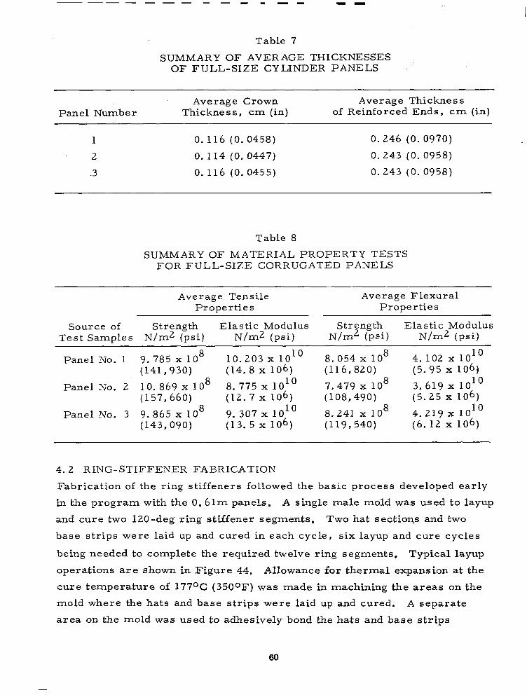
Table 7
SUMMARY OF AVERAGE THICKNESSES OF FULL-S1Z.E CYLINDER PANELS
Panel Number
1
2
.3
Average Crown Average Thickness Thickness, cm (in) of Reinforced Ends, cm (in)
0.116 (0.0458) 0.246 (0. 0970)
0.114 (0. 0447) 0.243 (0. 0958)
0. 116 (0. 0455) 0.243 (0. 0958)
Table 8
SUMMARY OF MATERIAL PROPERTY TESTS FOR FULL-SIZE CORRUGATED PANELS
Average Tensile Average Flexural Properties Properties
Source of Strength Elastic Modulus Strength Elastic Modulus Test Samples N/m2 (psi) N/m2 (psi) N/m2 (psi) N/m2 (psi)
Panel No. 1 9. 785 x 10 8 10.203 x lOlo 8.054 x lo8 4. 102 x 101’ (141,930) (14. 8 x 10⁶) (116,820) (5.95 x 10⁶)
Panel No. 2 10. 869 x lo8 8. 775 x lOlo 7.479 x lo8 3.619 x lOlo (157,660) (12.7 x 10⁶) (108,490) (5.25 x 10⁶)
Panel No. 3 9.865 x lo8 9.307 x 1o1O 8.241 x lo8 4.219 x io1O
(143,090) (13.5 x 10⁶) (119,540) (6.12 x 10⁶)
4.2 RING-STIFFENER FABRICATION
Fabrication of the ring stiffeners followed the basic process developed early
in the program with the 0.61m panels. A single male mold was used to layup
and cure two 120-deg ring stiffener segments. Two hat sections and two
base strips were laid up and cured in each cycle, six layup and cure cycles
being needed to complete the required twelve ring segments. Typical layup
operations are shown in Figure 44. Allowance for thermal expansion at the
cure temperature of 177OC (3500F) was made in machining the areas on the
mold where the hats and base strips were laid up and cured. A separate
area on the mold was used to adhesively bond the hats and base strips
60

Figure 44. Layup of Ring-Stiffener Seqnents
together, that area being machined to the required finish radius for the ring
stiffeners. The separate area was used because bonding was accomplished
at room temperature in contrast to the individual part cure at 177OC (350OF).
As a final step in completing the ring segments, the bonded parts were
trimmed to size. Hat-section splice segments were laid up and cured on a
separate small mold.
4.3 ASSEMBLY JIG
The NASA-furnished steel test rings were made an integral part of the
assembly jig so that the graphite-epoxy cylinder was constructed between
the two test rings. Three vertical steel I-beams with projecting angles
formed supports for the steel end rings (Figure 45). The jig was thus
arranged to assemble the corrugated panels vertically between the test rings
with the longitudinal axis of the cylinder in a vertical position. Vertical
aluminum posts were located on the inside of the cylindrical shell to provide
backup for the wall panel joints, and internal frames were located at each
61

Figure 46. View of Assembly Jig Showing Vertical Support Posts, Steel Test Rirrgs, and Internal Frames
62
ring stiffener position to provide forms for the corrugated panels and backup
when assembling the ring stiffeners to the shell wall.
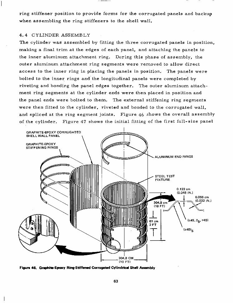
4.4 CYLINDER ASSEMBLY
The cylinder was assembled by fitting the three corrugated panels in position,
making a final trim at the edges of each panel, and attaching the panels to
the inner aluminum attachment ring. During this phase of assembly, the
outer aluminum attachment ring segments were removed to allow direct
access to the inner ring in placing the panels in position. The panels were
bolted to the inner rings and the longitudinal panels were completed by
riveting and bonding the panel edges together. The outer aluminum attach-
ment ring segments at the cylinder ends were then placed in position and
the panel ends were bolted to them. The external stiffening ring segments
were then fitted to the cylinder, riveted and bonded to the corrugated wall,
and spliced at the ring segment joints. Figure 46 shows the overall assembly
of the cylinder. Figure 47 shows the initial fitting of the first full-size panel
GRAPHITE-EPOXY CORRUGATED I
SHELL WALL PANEL
GRAPHITE-EPOXY STIFFENING RINGS
ALUMINUM END RINGS
Figun 46. Graphite-Epacy RinpStiffmod Camugated Cylindrical Shdl AssamMy
63

Figure 47. Init/al Corrugated Panel Positioned in Assembly Jig
64

I -
in the assembly jig. Plastic straps were used to hold the panel in position
while it was being adjusted to match the end rings and determination of final
edge trim requirements was being made.
The flexibility of the corrugated panels in a radial direction is easily seen
in Figure 48, in which a full-size panel is being removed from a storage
unit in preparation for placement in the assembly jig. The thin-walled
corrugations were easily flexed with no damage to the panels. Figure 49
shows a view of the internal side of the cylinder wall with the corrugated
forms providing a backup for the panels at each ring-stiffener position.
Detailed views of the internal and external attachment rings and one of the
steel test rings are presented in Figures 50 and 51. The completed cylinder
is shown in Figure 52.
65

Figure 49. Cornrgated Panel Flexibility Ourbrg Removal from Storage Unit
Figure 49. View of Internal Side of Cyclinder Wall

Figur ‘0 50. II nternal View of Cylinder End, Shciwing Aluminum Attachmbnt Rings and Steel Test Ring
Figul 51. E ixtemal View of Cylinder End, Showing Aluminum Attachment Ring Semen- and Steel Ts nt Ring
67
I
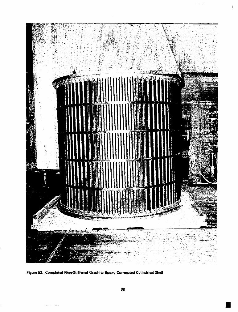
Figure 52. Completed Ring-Stiffened Graphite-Epoxy Corrugated Cylindrical Shell
66

Section 5
CYLIrjDER COST AND WEIGHT ANALYSIS
Cost and weight analyses were conducted as a part of the program to assess
those important aspects of the use of advanced composites in large, lightly
loaded shell structures. Cost projections for producing 100 units were
developed based upon fabrication efforts during the program. The projections
were then’modified to account for learning curve effects plus more
sophisticated tooling as appropriate for 100 units. Weight estimates were
developed initially and updated as nec,essary. Actual weights of the finished
components were obtained during and after assembly of the cylinder for
comparison with computed weights.
5. 1. COST ANALYSIS
A cost analysis for production of 100 units was conducted to determine the
projected cost for production quantities of a graphite-epoxy cylindrical shell
structure. The fabrication approach assumed for the cost study was basically
the same as used in this program: however, tooling modifications were
assumed as required for quantity production, and more extensive use of
tooling aids was assumed for operations such as trimming the panel edges
and ring stiffeners. A material cost of $44 per kg ($20/lb) was assumed for
the T300/5208 graphite-epoxy prepreg tape.
Production of the 100 units was assumed to occur over a 5-year period with
all costs based on January 1978 dollars and an assumed production rate of
20 units per year. Profit or fee was not included in the estimated cost of the
100 units. To account for improvement in production performance as the
program progresses, a 90% learning curve was used for all recurring costs.
Tooling and manufacturing improvements assumed for large- scale production
were:
1. Permanent tooling would be provided for manufacture of the
aluminum adapter and load-introduction rings.
69

2. A second mold for panel layup and cure would be provided to sustain
the production rate of 20 cylinders per year based on a 5-day,
Z-shift work week.
3. The main assembly fixture would be a complete entity and include
locating, positioning and holding attachments for the panels and
hat sections. A permanent assembly fixture would be fabricated
for the program.
4. The rubber vacuum bag used in panel curing operations would be a
purchased item, carried in stock in sufficient quantity to accom-
modate the anticipated life span of each bag (12 units or 36 panels).
5. The main panel layup operation would be optimized by using fixtures
to support the *45-deg preplies and by providing platforms for
improved access and reduced layup time.
6. Permanent trim fixtures would be provided for panel and ring-
stiffener trimming.
Using the above assumptions, a total cost for production of 100 units was
projected to be $6, 217, 000.
Past studies of cylindrical shells in which cost comparisons of aluminum
and advanced composite structures of the same basic shell have been made
show a moderate cost saving for the composite structure when the number of
parts can be reduced significantly over the aluminum counterpart.
5.2 WEIGHT ANALYSIS
A summary of the computed weights of the ring-stiffened graphite-epoxy
corrugated shell, the aluminum rings, and the steel test rings are presented
in Table 9. Calculated weights for the graphite-epoxy components were
based upon a material density of 152. 5 kg/m3 (0. 055 lbm/in. 3) for the
finished parts. Individual graphite-epoxy components were weighed prior
to assembly of the shell for comparison with the computed weights shown
in Table 9. Some elements, such as end reinforcing doublers on the cor-
rugated panels, were cocured with the panels and thus could not be weighed
separately. Consequently, comparisons were made where possible by
summing computed weights of individual elements shown in Table 9 and
comparing those sums with the actual part weights. Such comparisons are
70
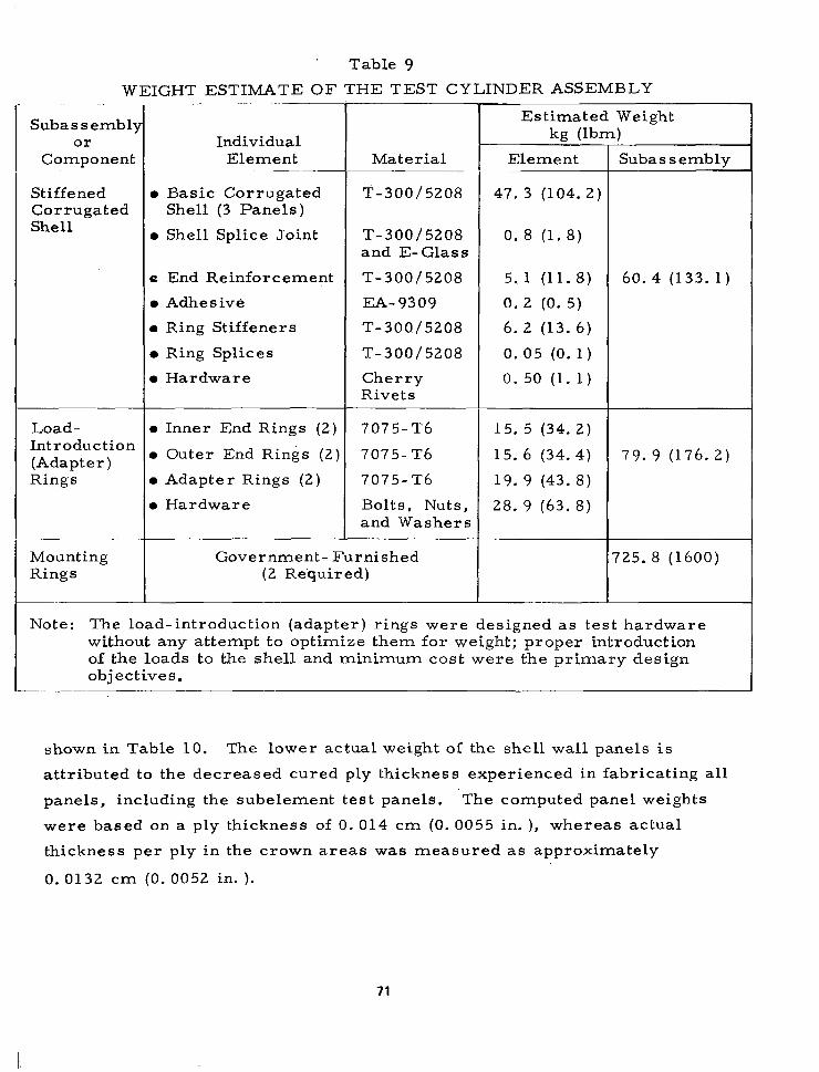
Table 9
WEIGHT ESTIMATE OF THE TEST CYLINDER ASSEMBLY
Subassembl) or
Component
Stiffened Corrugated Shell
Load- Introduction (Adapter) Rings
Mounting Rings
Individual Element
l Basic Corrugated Shell (3 Panels)
l Shell Splice Joint
e End Reinforcement
l Adhesive
l Ring Stiffeners
l Ring Splices
l Hardware
l Inner End Rings (2)
l Outer End Rings (2)
l Adapter Rings (2)
l Hardware
Material
T-300/5208
T-300/5208 and E- Glass
T-300/5208
EA-9309
T-300/5208
T-300/5208
Cherry Rivets
7075-T6
7075- T6
7075- T6
Bolts, Nuts, and Washers
Government- Furnished (2 Required)
Estimated Weight kn (lbm) -
Element
47. 3 (104.2)
0. 8 (1. 8)
5. 1 (11.8)
0. 2 (0. 5)
6. 2 (13. 6)
0. 05 (0. 1)
0.50 (1.1)
15. 5 (34. 2)
15. 6 (34. 4)
19. 9 (43. 8)
28. 9 (63. 8)
Subas s emblv
60. 4 (133. 1)
79. 9 (176. 2)
725. 8 (1600)
Note: The load-introduction (adapter) rings were designed as test hardware without any attempt to optimize them for weight; proper introduction of the loads to the shell and minimum cost were the primary design objectives.
__-
shown in Table 10. The lower actual weight of the shell wall panels is
attributed to the decreased cured ply thickness experienced in fabricating all
panels, including the subelement test panels. ‘The computed panel weights
were based on a ply thickness of 0.014 cm (0. 0055 in. ), whereas actual
thickness per ply in the crown areas was measured as approximately
0. 0132 cm (0. 0052 in. ).
71
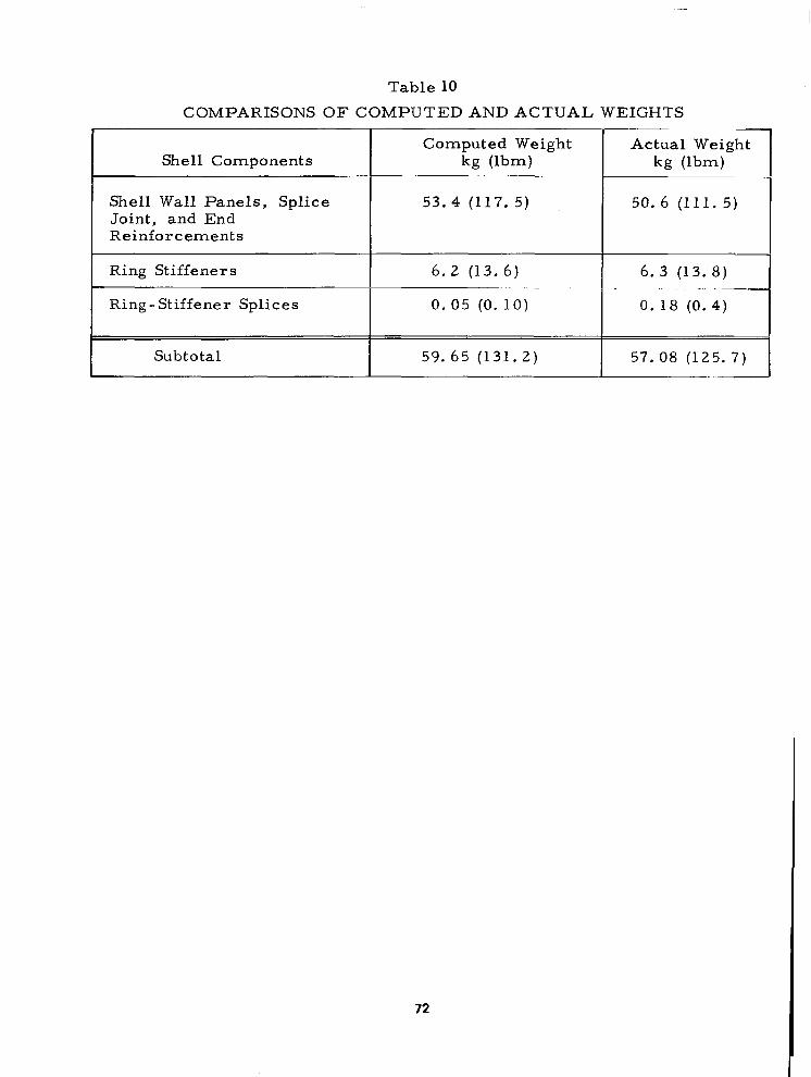
Table 10
COMPARISONS OF COMPUTED AND ACTUAL WEIGHTS
Shell Components
Shell Wall Panels, Splice Joint, and End Reinforcements
Computed Weight Actual Weight kg Ubm) kg (lbm)
53.4 (117. 5) 50. 6 (111. 5)
Ring Stiffeners 6. 2 (13. 6) 6. 3 (13. 8) -_
Ring-Stiffener Splices 0.05 (0.10) 0. 18 (0. 4)
Subtotal 59. 65 (131.2) 57. 08 (125. 7)
72

Section 6
CONCLUSIONS
A graphite-epoxy cylinder 3. 05m (10 ft) in diameter and 3. 05m (10 ft) long
was designed and fabricated by using T300/5208 as the basic material for
the’corrugated wall and the external stiffening rings. To ease assembly and
to maintain good dimensional control of the cylinder, the shell wall was made
in three 120-deg segments, as were each of the four stiffening rings. Pre-
liminary compression tests conducted with subsize test panels having the
full-scale corrugation cross section provided design data required to refine
the shell wall design.
The fabrication techniques developed in building the subsize corrugated test
panels were successfully applied to the full-size cylinder wall panels, each
of the three panels having dimensions of approximately 3. 23 by 3. OOm
(127 by 118 in. ). Fabrication of the 3. 05m (10 ft ) diameter graphite-epoxy
cylinder demonstrated the feasibility of using lightweight advanced composites
in lightly loaded full-size space vehicle structures. A 230/O weight saving
was achieved in the T300/5208 graphite-epoxy test cylinder when compared
to an aluminum cylinder of the same basic design.
The following conclusions resulted from the work conducted in this program:
1. The flexibility of an open-corrugation design for a cylindrical shell
wall permits a simplified manufacturing approach whereby flat
corrugated panels may be laid up, cured, and subsequently
wrapped to shape upon assembly.
2. Compression tests with flat panels of the open-corrugation con-
figuration showed the ability to sustain the design load of 1576 N/cm
(900 lb/in. ) without local buckling when a layup of [*45,05, $451 was
used in the crowns.
3. Aluminum tooling provided adequate dimensional stability for curing
the T300/5208 tape prepreg parts at 177°C (350°F).
4. Actual weights of graphite-epoxy components were accurately pre-
dicted by preliminary analyses.
73


REFERENCES
1. Williams, Jerry G. , and Mikulas, Martin M. , Jr. Analytical and Experimental Study of Structurally Efficient Composite Hat-Stiffened Panels Loaded in Axial Compression. ASME/AIAA/SAE 16th Structures, Structural Dynamics, and Materials Conference, Denver, Colorado, May 1975, AIAA Paper No. 75-754.
2. Agarwall, B. L. , and Davis, R. C. Minimum-Weight Designs for Hat- Stiffened Composite Panels Under Uniaxial Compression. NASA TN D-7779, 1974.
3. Bushnell, David. Stress, Stability, and Vibration of Complex Branched Shells of Revolution: Analyst’s and User’s Manual for BOSOR 4. NASA CR-21 16, 1972.
4. Anderson, M. S., Hennesy, K. W., and Heard. W. L. Addendum to User’s Guide to VIPASA. NASA TMX-73914, May 1976.
5. Viswanathan, A. V., Tamekuni, M., and Baker, L. L. Elastic Stability of Laminated, Flat and Curved, Long Rectangular Plates Subjected to Combined Inplane Loads. NASA CR-2330, June 1974.
6. Peterson, J. P., and Anderson, J. K. Bending Tests of Large-Diameter Ring-Stiffened Corrugated Cylinders. NASA TN D-3336, 1966.
75

1. Report No. 2. Government Accession No. 3. Recipient’s Catalog No.
NASA CR-3026 4. Title and Subtitle 5. Repxt Date
Design and Fabrication of a Ring-Stiffened Graphite-Epoxy - August 1978.
Corrugated Cylindrical Shell 6. Performing Organization Code
-_--
7. Author(s) 8. Performing Orqaruzation Report No.
Read Johnson, Jr. MDC.G7330
10. Work Unit No.
9. Performing Organization Name and Address
McDonnell Douglas Astronautics Company 5301 Bolsa Avenue Huntington Beach, CA 92647
12. Sponsoring Agency Name and Address
National Aeronautics and Space Administration Washington, D. C. 20546
._ 1 13. Type of Report and Period Covered
I5 Supplementary Notes
Langley Technical Monitor: Randall C. Davis Final Report
16. Abstract The work conducted from 30 July 1976 through 31 January 1978 in a program to design and fabricate a graphite-epoxy cylindrical shell 3.05111 (10 ft) in diameter by 3.05 (10 ft) long is described. Design and fabrication of subelement test panels that represent key portions of the cylinder are also described, as are supporting tests of coupons, sample joints, and stiffening ring elements. The cylindrical shell is a - ring-stiffened, open corrugation design that uses T300/5208 graphite-epoxy tape as the basic material for the shell wall and stiffening rings. The test cylinder, which is to be tested at the NASA Langley Research Center, is designed to withstand bending loads producing the relatively low maximum load intensity in the shell wall of 1,576 N/cm (900 lb/in). The resulting she 1 wall weight, including stiffening rings and fasteners, is 0.0156 kg/m2 (0.37 lb/ft h ). The shell weight achieved in the graphite-epoxy cylinder represents a weight saving of approximately 23%, compared to a comparable aluminum shell. A unique fabrication approach was used in which the cylinder wall was built in three flat segments, which were then wrapped to the cylin- drical shape. Such an approach, made possible by the flexibility of the thin corrugated wall in a radial direction, proved to be a simple approach to building the test cylinder. Based on tooling and fabrication methods in this program, the projected costs of a production run of 100 units are reported.
17. Key Words (Suggested by Author(s)) 18. Distribution Statement
Cylinder, corrugation, graphite/epoxy, composite, stiffened, lightweight,rings, shell, fabrication.
Distribution is unlimited
Subject Category 39 -- _
19. Security Classif. (of this report) 20. Security Classif. (of this page) 21. No. of Pages 22. Price’
Unclassified Unclassified 76 $6.00
* For sale by the National Technical Information Service, Springfield. Virginia 22161 NASA-Langley, 1978
![THE DESIGN, FABRICATION, HYDROSTATIC TEST, … design, fabrication, hydrostatic test, and failure analysis of a 610 mm i.d. as-4/apc-2 ring-stiffened [90n/0] pressure hull model mark](https://static.fdocuments.in/doc/165x107/5b072ea67f8b9a5c308dff46/the-design-fabrication-hydrostatic-test-design-fabrication-hydrostatic-test.jpg)


![Fabrication of isotropic bulk graphite using artificial graphite …142-145]-09.pdf · 2014-04-29 · 2.1. Raw materials and preparation The raw powder used in the present study was](https://static.fdocuments.in/doc/165x107/5e35bf8b7ae30b73af2cd2ea/fabrication-of-isotropic-bulk-graphite-using-artificial-graphite-142-145-09pdf.jpg)