Design and experimental testing of the bundled glass...
19
Delft University of Technology Design and experimental testing of the bundled glass column Oikonomopoulou, Faidra; van den Broek, E.A.M.; Bristogianni, Telesilla; Nijsse, Rob; Veer, Fred DOI 10.1007/s40940-017-0041-x Publication date 2017 Document Version Publisher's PDF, also known as Version of record Published in Glass Structures and Engineering Citation (APA) Oikonomopoulou, F., van den Broek, E. A. M., Bristogianni, T., Nijsse, R., & Veer, F. A. (2017). Design and experimental testing of the bundled glass column. Glass Structures and Engineering, 1-18. DOI: 10.1007/s40940-017-0041-x Important note To cite this publication, please use the final published version (if applicable). Please check the document version above. Copyright Other than for strictly personal use, it is not permitted to download, forward or distribute the text or part of it, without the consent of the author(s) and/or copyright holder(s), unless the work is under an open content license such as Creative Commons. Takedown policy Please contact us and provide details if you believe this document breaches copyrights. We will remove access to the work immediately and investigate your claim. This work is downloaded from Delft University of Technology. For technical reasons the number of authors shown on this cover page is limited to a maximum of 10.
Transcript of Design and experimental testing of the bundled glass...

Delft University of Technology
Design and experimental testing of the bundled glass column
Oikonomopoulou, Faidra; van den Broek, E.A.M.; Bristogianni, Telesilla; Nijsse, Rob; Veer, Fred
DOI10.1007/s40940-017-0041-xPublication date2017Document VersionPublisher's PDF, also known as Version of recordPublished inGlass Structures and Engineering
Citation (APA)Oikonomopoulou, F., van den Broek, E. A. M., Bristogianni, T., Nijsse, R., & Veer, F. A. (2017). Design andexperimental testing of the bundled glass column. Glass Structures and Engineering, 1-18. DOI:10.1007/s40940-017-0041-x
Important noteTo cite this publication, please use the final published version (if applicable).Please check the document version above.
CopyrightOther than for strictly personal use, it is not permitted to download, forward or distribute the text or part of it, without the consentof the author(s) and/or copyright holder(s), unless the work is under an open content license such as Creative Commons.
Takedown policyPlease contact us and provide details if you believe this document breaches copyrights.We will remove access to the work immediately and investigate your claim.
This work is downloaded from Delft University of Technology.For technical reasons the number of authors shown on this cover page is limited to a maximum of 10.
Glass Struct. Eng.DOI 10.1007/s40940-017-0041-x
S.I . : GLASS PERFORMANCE PAPER
Design and experimental testing of the bundled glass column
F. Oikonomopoulou · E. A. M. van den Broek ·T. Bristogianni · F. A. Veer · R. Nijsse
Received: 15 February 2017 / Accepted: 10 April 2017© The Author(s) 2017. This article is an open access publication
Abstract Glass columns are a promising solution fortransparent structural members, capable of transferringthe compressive loads in a building while allowing forlight and space continuity. Several different types of all-glass columns have been explored in the past, neverthe-less, they are seldom applied in construction. Reasonsinclude complications in fabrication, lack of adequatestrength data but foremost the decreased safety due tothe inherent brittleness of glass. This work presents theengineering steps towards the realization of the bundledglass column, from its fabricationmethod to the experi-mental testing of series of prototypes in several lengths.Composed of multiple adhesively bonded standardizedextruded borosilicate rods, this column can be manu-factured relatively easily, achieving a high visual resultand sufficient load-bearing capacity. Initially, compres-sive testing is conducted on series of small-scale proto-types to evaluate the degree of coupling of the rods andthe influence of spliced joints along the length of theindividual components. Based on the findings, proto-types on a scale relevant to buildings are produced and
F. Oikonomopoulou (B) · E. A. M. van den Broek ·F. A. Veer · R. NijsseDepartment of Architectural Engineering + Technology,Faculty of Architecture and the Built Environment, DelftUniversity of Technology, 2628 BL Delft, The Netherlandse-mail: [email protected]
T. Bristogianni · R. NijsseDepartment of Structural Engineering, Faculty ofCivil Engineer-ing and Geosciences, Delft University of Technology, 2628 CNDelft, The Netherlands
experimentally tested. Finally, prototypes with post-tensioning are also tested in compression andevaluated,in an attempt to transform the sudden, brittle mode offailure into ductile. The results demonstrate that thedesigned bundled column can perform monolithicallyunder loading and has sufficient load-carrying capacityto be considered a structural element. Post-tensioningof the column can contribute to a consistent failurebut further development is necessary so that sufficientcooperation between the glass and the steel tendon isachieved.
Keywords Structural glass · Bundled column ·Glass columns · Extruded glass profiles · Glass rods ·Adhesive joints
1 Introduction
1.1 The potential of all glass columns
Large, column-free spaces have long fascinated archi-tects worldwide as they allow for unobstructed viewsand space and light continuity.Nevertheless, the absenceof columns in a building is often linked with expensiveand complex structural solutions. Transparent columns,made of glass, could be a promising answer to thisconflict between architecture and structural engineer-ing. Revealed only by the play of light and of reflec-tions, free-standing glass columns would disrupt theopenness of a space the least while forming structural
123

F. Oikonomopoulou et al.
Fig. 1 The five differenttypes of all glass columns asdescribed by Nijsse and tenBrincke (2014)
members capable of transferring vertical loads. Indeed,glass’s characteristic properties of transparency, dura-bility and of a compressive strength up to 1000N/mm2
(Saint Gobain 2016), exceeding that of wood, concreteand even steel (Granta Design Limited 2015), renderit the most suitable candidate for realizing diaphanouscompressive members. Nevertheless, despite the con-tinuously ascending use of glass in structural com-ponents such as beams, portals, shear walls and self-carrying façades over the last decades, free-standingglass columns are still in a very early stage of develop-ment. This can be attributed to the insufficient knowl-edge regarding their structural behaviour and load car-rying capacity under exceptional loading conditions(Kalamar et al. 2016).
1.2 Previous examples of all glass columns
To the knowledge of the authors, at present, glass pro-file columns of a cruciform (X) cross-section are theonly type of free-standing glass columns applied inbuildings. The first realized example, built in 1994 inSt-Germain-en-Laye in France, comprises eight 3.2mhigh cruciform glass columns that support a glass patio.The cruciform profile was selected due to its increasedresistance to buckling (Schittich et al. 2007). The sametypology of columns was later followed at the Dan-foss Headquarters in Denmark, where twelve 5.5mhigh cruciform columns support the reception build-ing (Petersen and Bagger 2009). The inclusion of thecolumns was only possible after performing 1:1 scaleloading tests in which the components demonstrated
the ability to carry much higher compressive forcesthan required. Specifically, the columns applied in theSt-Germain-en-Laye office could withstand a forceequal to approximately 6 times the calculated maxi-mum load (Nijsse 2003). A series of structural exper-iments on a full-scale specimen for the Danfoss head-quarters proved that even after the column is severelydamaged from hard impact under loading, it can stillcarry an axial load greater than twice the expectedmax-imum force (Petersen and Bagger 2009). Thus, in bothexamples, the tested columns present a safety factor>2. Still, due to the unpredictable and sudden fail-ure of glass, in both cases, the roof is designed withsufficient redundancy to redistribute the forces in caseone or more glass columns fail in a complete way(Petersen and Bagger 2009; Nijsse 2003). These twocase studies exhibit both the potential and the engineer-ing constraints of all glass columns. Despite havingmore than adequate load-bearing capacity, the appli-cation of glass columns in buildings is linked withincreased safety factors compared to standard mate-rials, as well as with the design of alternative loadpaths to compensate for the lack of a built-in safetysystem.
Beside these two examples, other configurations offree-standing glass columns have, at present, only beenexplored within research context and tested in lengthstypically restricted to 1.5m. Exploring the possibilities,(Nijsse and ten Brincke 2014) introduce the followingfive design concepts of free-standing all-glass columns,illustrated in Fig.1: profile, layered tubular, stacked,cast, and bundled. Table 1 summarizes the geometrical
123

Design and experimental testing of the bundled glass column
Table 1 Geometrical and mechanical properties of characteristic examples of the five types of free-standing columns as stated inliterature
Columntype
Configuration Cross-section(mm)
d ofindividualelements(mm)
Numberofglasslayers (–)
L (mm) F∗failure
in axialloading(kN)
σfailure(MPa)
Application
X-profilea One continuouslaminated panel andone split in twobonded with a clearsilicone
449×449 12 3 5500 575k 18.53 DanfossOffice
X-profileb One continuouslaminated panel andone split in twobonded with a hardadhesive
400×400 10/15/10 3 3300 430 16.06 St-Germain-en-Laye
H-profilec Single 8mm panesbonded withHercuseal polymer
116×100 8 1 1000 212–255 88.4–106.6 Academicresearch
Tubulard 1 borosilicate tube Ø150 5 1 4100 221 97.3 Academicresearch
Layeredtubulare
2 coaxial borosilicateglass tubes laminatedtogether bylow-shrinkage clearresin
Øout:120Øint:95
5 2 1500 137–196 40.6–57.9 Academicresearch
Stackedf 50 horizontally stackedfloat panels bondedtogether by SilverTape8502
100×100 12 50 hori-zontally
615 525 52.5 Academicresearch
Castg 10 solid cast glassblocks bondedtogether byDelo-Photobond 4468
105×105 65 10 hori-zontally
650 1412 128.0 Academicresearch
Bundledh 3 hollow tubes bondedtogether by a lowmodulus structuralsilicone
3 j Ø24 2.5 3 1500 13.37 26.4 Academicresearch
Bundledi 7 rods of Ø30mmbonded together by aclear UV-curingadhesive
Approx. Ø90 30 7 1600 Not tested Not tested Engineeringconcept
Geometrical and mechanical data provided for a Petersen and Bagger (2009), b Schittich et al. (2007) c Ouwerkerk (2011), d Achenbachand Jung (2003), e Nieuwenhuijzen et al. (2005), f,g Felekou (2016), h Kamarudin et al. (2016), i Nijsse (2003)j All values provided here concern the force at total failure of specimens tested in compression. Typically testing was performed on oneor two specimens, so the derived experimental data cannot be considered statisticalk The prototype failed at this value after having been subjected to soft and hard impact while loaded to the calculated serviceabilitylimit state axial load of 190kN
and mechanical properties of characteristic samples ofthe five column types described in this section.
Alternative configurations of profile columns, i.e.H, T, X and square profiles, and their compressivebehaviour have been explored experimentally, numer-
ically and analytically by Ouwerkerk (2011), Aielloet al. (2011), Campione and Rondello (2014), Overendet al. (2005) and Kalamar et al. (2016). The findingsdemonstrate that the 3-dimensional geometry of suchglass columns results in an increased structural resis-
123
F. Oikonomopoulou et al.
tance and stiffness. Most importantly, they manifestthat the adhesive connections between the glass ele-ments are of crucial importance to the overall perfor-mance. Research and experimental work has been con-ducted on tubular columns by Achenbach and Jung(2003), Overend et al. (2005), Nieuwenhuijzen et al.(2005) and Veer and Pastunink (1999). Actually, glasstubes have been previously structurally applied but notin the form of columns, with the most characteris-tic examples being tensegrity structures by the Uni-versity of Stuttgart (Achenbach et al. 2002) and theglass atrium façade of the Tower Place office build-ing in London (Doenitz et al. 2003). In the latter, theapprox. 40 glass tubes that transfer the wind forcesto the primary load-bearing system, consist of a coretube laminated to a split tube functioning as an externalprotecting shell and have a built-in steel cable system.In contrast, the developed column by Nieuwenhuijzenet al. (2005) and Veer and Pastunink (1999) consistsof two concentric glass tubes, laminated together bya clear low-shrinkage resin, aiming on utilizing struc-turally the entire glass composition. This productionprocess, however, involved several practical implica-tions due the adhesive’s shrinkage and the dimensionalintolerances of the glass tubes. A horizontally stacked,translucent, column made of float glass panels bondedtogether by an adhesive film has been explored by VanHeugten (2013) and Felekou (2016). Cast and bun-dled glass columns are until now the least exploredoptions. In theory, cast glass columns could form theideal solution for transparent load-bearing components.Through casting,monolithic, entirely transparent struc-tural glass members of the desired form and cross-section could be materialized. However, casting glassin such large volumes requires a precise and excessivelytime-consuming cooling process that renders the man-ufacturing of storey-high glass columns cost- and time-inefficient. This can be well illustrated by the “Oppo-sites of white” cast sculptures by artistRoni Horn. Eachdrum-shaped sculpture, 50.8cm high by 142cm diam-eter, required 4months of controlled annealing to pre-vent the generation of residual stresses (Kroller-MullerMuseum 2007). The even larger glass mirror ofHale-1telescope, following a honeycomb structure and mea-suring 5m in diameter and 0.66m in thickness, required10months of annealing (Corning Museum of Glass2011). To overcome the practical limitations involved,the concept of a dry-assembly column consisting ofinterlocking, vertically stacked, cast glass units of max.
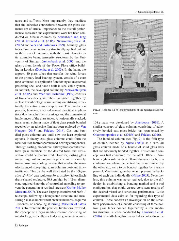
Fig. 2 Realized 1.5m long prototypes of the bundled glass col-umn
10kg mass was developed by Akerboom (2016). Asimilar concept of glass columns consisting of adhe-sively bonded cast glass bricks has been tested byOikonomopoulou et al. (2015b) and Felekou (2016).
The bundled column (see Fig. 2) is the fifth typeof column, defined by Nijsse (2003) as a safe, allglass column made of a bundle of solid glass barsthat are adhesively bonded together. This column con-cept was first conceived for the ABT Office in Arn-hem: 7 glass solid rods of 30mm diameter each, in aconfiguration where the central one is surrounded bythe other six, were to be bonded together by a trans-parent UV-activated glue that would prevent the buck-ling of each bar individually (Nijsse 2003). Neverthe-less, this column was never realized, due to the dif-ficulty in establishing a bonding method and a rodconfiguration that could ensure consistent results ofthe desired visual and structural performance. Littleexperimental data exist so far regarding this type ofcolumn. These concern an investigation on the struc-tural performance of a bundle consisting of three hol-low glass tubes bonded together by a low modu-lus structural silicone conducted by Kamarudin et al.(2016). Nevertheless, this research does not address the
123

Design and experimental testing of the bundled glass column
Fig. 3 Left CONTURAX® and DURAN® profiles. Right Concluded configuration of the bundled glass column
attained optical result when bonding the tubes with thismethod.
1.3 Realizing the bundled glass column
This paper presents the research and experimental test-ing and discusses the feasibility of the fifth type of glasscolumns, the bundled. This alternative has not beenexplored in depth until now even though it presentsgreat prospects in terms of fabrication, visual resultand structural performance. In this work, a productionmethod for constructing bundled glass columns on ascale relevant to buildings is first described, analysingthe practical limitations and proposed solutions. Fol-lowing, series of prototypes in different scales aremadeand tested in compression and the results are discussedin terms of structural performance. Lastly, in an attemptto introduce a more gradual and visible buckling fail-ure the concept of post-tensioning is introduced to full-scale specimens and experimentally evaluated. Basedon the findings, suggestions are made for further engi-neering the bundled column.
2 Design concept and production considerations
The concept of the bundled column is simple. Multipleglass bars are bonded together by a colourless adhe-sive, forming a composite yet integral cross-section. Interms of visual performance, the bundled glass columnis transparent, yet not invisible. The curved geome-try of the rods generates playful distortions and light
reflections, subtly revealing the existence of the col-umn (Oikonomopoulou et al. 2016). The column’sload-carrying capacity is enhanced by the symmetri-cal cross-section of both the rods and the compos-ite shape. Solid rods of a circular cross-section fromthe DURAN® series by Schott are selected due totheir inherent resistance in buckling and torsion. Theseare standardized, extruded borosilicate glass rod pro-files, 1500mm in length, with diameters ranging from3(±0.14) to 30(±0.80)mm (SCHOTT 2012). To cre-ate a symmetrical bundle, a configuration comprisingseven extruded profiles, a central one surrounded bysix external ones, is further examined. Initially, differ-ent fabrication methods comprising seven rods of iden-tical circular cross-section were explored. Such a rodarrangement proved incapable of guarantying a con-sistent visual and structural result, due to its inabilityto account for the standard diameter deviation of therods and the visible distortions caused by the adhe-sive lines (Oikonomopoulou et al. 2016). A new con-figuration was proposed, consisting of a central hol-low star-shaped CONTURAX® profile and six exter-nal DURAN® rods with a diameter corresponding tothe convex of the flutes of the central star profile. TheCONTURAX® profile is commercially only availablewith a 17(±2.00)mm inner and 30(±2.00)mm exter-nal diameter (SCHOTTAG2013). Tomatch the centralprofile’s curvature, the six externalDURAN® rods havea diameter of 22(±0.45)mm (see Fig. 3). The construc-tion of several prototypes proved that thematching cur-vature between the surface of the rods and the flutes ofthe central profile allows for consistent bonding stripes
123

F. Oikonomopoulou et al.
of a high visual result, despite the tolerances in the sizeof the individual components (Oikonomopoulou et al.2016).
The adhesive connection between adjacent glasscomponents plays a key role in the overall structuralperformance of glass columns (Kalamar et al. 2016).Thus, the degree of mechanical collaboration betweenthe rods is highly dependent on the applied adhe-sive. The higher the bonding strength, the more theadjacent elements couple, preventing individual buck-ling. Delo Photobond 4468, a one-component, clear,UV-curing acrylate, was selected for bonding the ele-ments together due to its colourless nature, similarrefraction index to glass, fast application and verygoodmechanical properties (Delo Industrial Adhesives2014). The specific adhesive was also applied in theconstruction of the Crystal Houses façade in Amster-dam (Oikonomopoulou et al. 2017). 4-point bendingexperiments on glass beams consisting of adhesivelybonded solid glass bricks by Oikonomopoulou et al.(2015a) demonstrated the monolithic behaviour of theglass-adhesive assembly under loading.
3 Fabrication of the prototypes: materials andmethods
3.1 Overview of specimens
Based on the proposedmanufacturingmethod, series ofspecimens in different scales are made and experimen-tally tested in compression. Figure 4 shows an illustra-tion of the series of prototypes and Table 2 summarizestheir geometrical characteristics and boundary condi-tions.
Compression testing is initially carried out on seriesof small prototypes [A1 and A2] to evaluate the degreeof coupling between the rods when bonded with theselected adhesive, as well as the influence of splicedconnections along the length of the rods. For this pur-pose, the results of these series will be discussed sep-arately in Sect. 4, since they are used as the basis forthe fabrication of longer specimens. Following, seriesof specimens in a scale relevant to buildings [B1 andB2] are tested in compression until failure and theresults are discussed in terms of load-carrying capac-ity and failure behaviour. Finally, a series of proto-types with an introduced axial post-tensioned steel ten-don [C1] is built and tested in compression with the
Fig. 4 Illustration of all specimen series tested in compression
aim of attaining a more gradual and visible bucklingfailure.
3.2 Production method of the glass bundle
Based on the findings of Sect. 2, each specimen con-sists of a central hollow star-shaped CONTURAX®borosilicate glass profile with 17(±2.00)mm inner and30(±2.00)mm external diameter adhesively bonded to6 borosilicate DURAX® rods of Ø 22(±0.45)mm,which form the external bundle (see Fig. 5).
The rods are bonded one by one in a horizontal posi-tion to the flutes of the central profile along their length,in a strip approx. 8mmwide, byDelo Photobond 4468adhesive. The latter is fully cured during a minimumof 40s using 60mW/cm2 UVA intensity (Delo Indus-trial Adhesives 2014). An illustration of the bondingmethod can be seen in Fig. 6.
All glass profiles used are properly annealed inSchott’s premises. Each profile is carefully cut to sizeusing a diamond blade saw and its ends are manuallyground. Once the profiles are bonded together and thebundle is formed, the top and bottom surfaces are man-ually ground again carefully to remove any protrusionsdue to misalignment or difference in length of the indi-vidual rods and to obtain a flat surface perpendicular tothe axis.
123

Design and experimental testing of the bundled glass column
Table 2 Overview of the specimens’ characteristics
Specimenseries
Glass bundlecomposition
Least secondmoment of areaI (mm4)
Length(mm)
Endconditions
Splicedlamination
Post-tensioning No. ofspecimens
A1 6× Ø22 rods +1× star-shape
643170 500 Clamped No No 3
A2 3× Ø22 rods 126464 470 Clamped Yes No 12
B1 6× Ø22 rods +1× star-shape
643170 1500 Clamped No No 3
B2 6× Ø22 rods +1× star-shape
643170 2400 Pinned Yes No 3
C1 6× Ø22 rods +1× star-shape
643170 2400 Pinned Yes Yes 3
Fig. 5 The bundled column cross-section
3.3 End connections of specimens
3.3.1 Clamped connections of specimen series A1, A2
and B1
Specimens A1, A2 and B1 are tested while establishingclamped connections in the testing machine, as such:
At both ends of the bonded glass bundle two milledaluminium caps are mounted to form the top and bot-tom bases (see Fig. 7). The caps, besides stabilizingthe bundle, prevent direct contact between the glassand the steel surface of the testing machine. Prior tomounting, a soft, 1mm thick sheet of lead is placedinside each aluminium head (see Fig. 7). This yieldinginterlayer allows for the even distribution of the appliedcompression load, preventing peak stress concentra-tions due to possible unevenness in the glass’ contactsurface. The connection between the aluminium cap,coated with the inlayed lead, and the glass bundle isrealized by a clear adhesive. In specific, once the col-umn is aligned to be in the centre of the aluminiumhead, a two-component clear polyurethane is carefullymixed and poured in between the glass and aluminiumat the ground base to create a rigid head. Crystal Clear®
200 resin is chosen due to its water and UV- resistanceand negligible shrinkage (SMOOTH-ON 2016). Thisresin is left to cure for a minimum of 16h. Then thecolumn is flipped and the other side is treated the sameway.
Fig. 6 Schematic illustration of the bonding method applied tothe glass bundle. From left to right The rods are individuallybonded to the flutes of the central profile in a horizontal posi-
tion and cured by a UV-lamp travelling back and forth along itslength. The process is repeated for each rod until the bundle iscomplete
123

F. Oikonomopoulou et al.
Fig. 7 The aluminium cap with the inlayed lead sheet and asection of the glass bundle
3.3.2 Pinned connections of specimen series B2
In specimen series B2 the same aluminium cap connec-tions are applied, yet an addition is made to the detailso that the columns are tested in a pinned configuration.Specifically, a steel cap with a milled convex and a cor-respondinghalf-sphere steel component is placedunderthe base aluminium cap (see Fig. 8). For the top connec-tion the same detail is applied above the top aluminium
cap, by an identical steel cap welded to the steel sur-face of the testing machine (see Fig. 8). Prior to testing,the complete specimen is stabilized by restraining theheight of the column through carefully adjusting themachine’s top pressing plate so that contact is made.The force introduced before the experiment starts isnegligible.
3.3.3 Pinned connections of specimen series C1 andapplication of the post-tensioning
The production process for the C1, post-tensioned vari-ant of 2400mm length, is identical to the B2 series ofprototypes with the exception of the post-tensioningtendon and the use of steel top and bottom caps. Thehollow core of the central star-shaped CONTURAX®
borosilicate glass profile, of 17(±2.00)mm diameter,is used to accommodate the post-tensioning tendon.To account for the ±2.00mm production tolerance inthe inner diameter of this profile, a standardized M12threaded rod is used as tendon with PVC tubing, of16mm outer and 13.6mm inner diameter, around it, toprevent direct contact between the steel and the glass(see Fig. 9). Due to the inevitable production tolerancesof the CONTURAX® profile, the PVC-coated tendon
Fig. 8 Top (left) andbottom (right) pinnedconnections of theexperimental set-up of theB2 specimen series
Fig. 9 Left Position of thesteel tendon and PVC tubeat the post-tensionedspecimens. Right The steelcap detail
123

Design and experimental testing of the bundled glass column
Fig. 10 Illustration of the post-tensioned glass column head detail
is not in direct contact with the glass, but as close toglass as possible using stock materials.
Pre-stress applied to a tendon is dependent on thetype of steel. Although material properties vary, anapproximate estimate of proof strength is 85–90%of itsyield strength (Shigley and Mitchell 1993). Using 8.8bolt quality steel the torque value that can be safelyapplied is 80(±10)Nm, which translates to roughly35kN of axial force.1 The post-tensioning is appliedusing a Stahlwille 730/10 torque wrench with corre-sponding square drive which allows for a maximumtorque application of 100Nm.
In contrast to all previous specimens, the post-tensioned columns heads aremade of the same8.8 qual-ity steel as the post-tensioning tendon, nut and washer(see Fig. 9) for better cooperation of the components.The bottom steel cap has an axial hole with a femaleM12 thread in which the post-tensioned tendon can befixed. The top steel cap has a 13mm hole to allow freepassage of the tendon, which is tightened with a M12washer and nut using the torquewrench (see Fig. 10). Inthese steel heads a 1mm thick layer of lead is again usedas intermediary to prevent direct contact between the
1 A M12 of 8.8 quality steel has a tensile strength of approxi-mately 62.8kN. To bewithin a safemargin, the pre-stress appliedto the tendon was decided to be approx. 55% of this strength.Quality 8.8 bolt steel was chosen for this research as the use oflower quality steel, and consequently a lower amount of appliedpre-stress, would make the monitoring of the expected effectmore difficult. The use of 8.8 steel results as well into an appliedpre-stress lower than the critical buckling force. Thus, in caseof accidental damage of the column, the latter would not buckleunder the pre-stress applied alone.
glass column and the steel heads. The same pinned con-nection details between steel caps and testing machineare applied, as described in the B2 specimens.
4 Testing of A1 and A2 series: initial evaluation ofthe coupling degree between the rods and theinfluence of spliced connections
Prior to the production of longer specimens it wasessential to evaluate the degree of coupling betweenthe rods when bonded with the selected adhesive, aswell as the influence of spliced connections necessaryfor the fabrication of prototypes exceeding the stan-dardized rod length of 1500mm. Therefore, two seriesof small scale prototypes, namely A1 and A2, weremade and tested under compression to evaluate each ofthe two parameters respectively. These tests and theirresults are presented below.
Fig. 11 Experimental set-up of A1 specimens
123

F. Oikonomopoulou et al.
Table 3 Dimensions and failure stress values of the A1 specimen series
Specimen Length (mm) Composition of the bundle Surface area (mm2) Failure load (kN) Nominal compressivefailure stress (MPa)
1 500 6× Ø20 rods + 1× star-shape 2156 1009.9 468
2 500 6× Ø22 rods + 1× star-shape 2552 1320.2 517
3 500 6× Ø 22 rods + 1× star-shape 2552 1320.0 517
4.1 Testing of A1 series: evaluation of the degree ofcoupling of the rods
To examine the degree of coupling between the individ-ual rods, compression tests were conducted at the A1
series of prototypes of 500mm length. The experimen-tal set-up can be seen in Fig. 11. Table 3 summarizesthe dimensions, failure load and corresponding nomi-nal compressive stress of the three tested specimens.
All specimens failed in a sudden and complete wayat a consistent compressive stress of approximately500MPa. The high failure stress indicates that, owingto the lead sheet insert, edge flaws and unevenness onthe length of the individual glass rods have a minorinfluence, if any at all, to the total load-carrying capac-ity. Most importantly, the consistency and magnitudeof the failure stress values suggest that either the com-pressive strength of glass2 or the compressive shearstrength of the adhesive have been reached. In eithercase, it is safe to assume that the high shear stiffness ofthe selected adhesive enables the bundle to behave as asingle monolithic unit under a compressive force lessthan 1000kN.
4.2 Testing of A2 series: evaluation of the influence ofspliced connections
According to SCHOTTAG (2017), themaximumman-ufacturing length in extruded profiles is 10m, sufficientfor realizing even three-storey high columns. Never-theless, in practice, Schott’s extruded profiles are stan-dardized up to 1500mm length. Communication with
2 Assuming a complete collaboration between glass and adhe-sive and clamped connections, based on Euler’s formula forbuckling the theoretical critical buckling force would be approx.3800kN. This in turn, corresponds to a compressive stress ofapprox. 1500MPa, a value higher than the stated compressivestrength of glass. Hence, it is assumed that the specimens failunder compression.
the manufacturer suggested that longer profiles can beproduced only for orders exceeding 500U. Due to costrestrictions such an order was not possible. Hence, toproduce specimens applicable in abuilding scale, a con-figuration similar to the splice-lamination principlewasapplied. Specifically, the column is segmented so thatthe connection points spiral up along its height. In thisway, the generation of weaker zones is minimized. Tooptimize the material use of the standardized 1500mmrods, every split point of the spiral, splice-lamination isin 250mm absolute height distance from the split pointof the adjacent rod. An illustration of this scheme isgiven in Fig. 12.
The influence of three alternative connection types,each 2mm thick, to the column’s carrying capacity isfurther evaluated by the experimental testing of theA2 series of prototypes: an empty gap, a gap filledwithDelo Photobond 4494 adhesive and an aluminiumring connection. Delo Photobond 4494 is opted dueto its compatibility with Delo Photobond 4468, itsgoodmechanical properties (Delo Industrial Adhesives2016), medium viscosity and ability to form a 2mmthick joint.3 Aluminium (bonded with Delo Photobond4468 to the glass surfaces) is chosen due to its compa-rable to glass, yet slightly lower, Young’s Modulus.A series of three 470mm high specimens consistingeach of 3 adhesively bonded rods of Ø 22(±0.45)mm,where one is interrupted in the middle (see Fig. 13)are made for each connection type and tested until fail-ure in a displacement controlled hydraulic compressionmachine with a 1mm/min rate of loading. The resultsof each series, summarized in Fig. 14, are compared
3 Oikonomopoulou et al. (2017) states thatDelo Photobond 4468reaches its optimum bond strength when applied in a layer 0.2–0.3mm thick. In this case, the 2mm thickness of the joint requiresa thicker adhesive that can still guarantee a good collaborationbetween the glass components. Delo Photobond 4494, of thesame adhesive family, achieves a relatively lower strength bondbetween glass components, yet can be applied in the requiredthickness.
123
Design and experimental testing of the bundled glass column
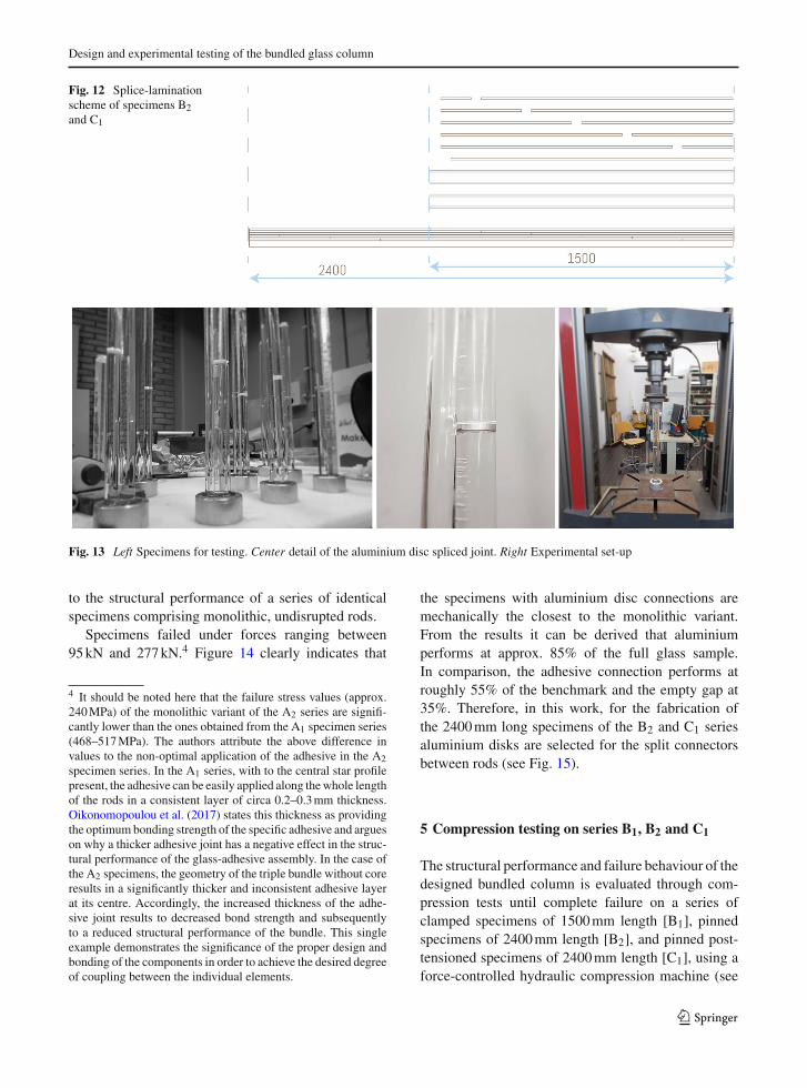
Fig. 12 Splice-laminationscheme of specimens B2and C1
Fig. 13 Left Specimens for testing. Center detail of the aluminium disc spliced joint. Right Experimental set-up
to the structural performance of a series of identicalspecimens comprising monolithic, undisrupted rods.
Specimens failed under forces ranging between95kN and 277kN.4 Figure 14 clearly indicates that
4 It should be noted here that the failure stress values (approx.240MPa) of the monolithic variant of the A2 series are signifi-cantly lower than the ones obtained from the A1 specimen series(468–517MPa). The authors attribute the above difference invalues to the non-optimal application of the adhesive in the A2specimen series. In the A1 series, with to the central star profilepresent, the adhesive can be easily applied along thewhole lengthof the rods in a consistent layer of circa 0.2–0.3mm thickness.Oikonomopoulou et al. (2017) states this thickness as providingthe optimumbonding strength of the specific adhesive and argueson why a thicker adhesive joint has a negative effect in the struc-tural performance of the glass-adhesive assembly. In the case ofthe A2 specimens, the geometry of the triple bundle without coreresults in a significantly thicker and inconsistent adhesive layerat its centre. Accordingly, the increased thickness of the adhe-sive joint results to decreased bond strength and subsequentlyto a reduced structural performance of the bundle. This singleexample demonstrates the significance of the proper design andbonding of the components in order to achieve the desired degreeof coupling between the individual elements.
the specimens with aluminium disc connections aremechanically the closest to the monolithic variant.From the results it can be derived that aluminiumperforms at approx. 85% of the full glass sample.In comparison, the adhesive connection performs atroughly 55% of the benchmark and the empty gap at35%. Therefore, in this work, for the fabrication ofthe 2400mm long specimens of the B2 and C1 seriesaluminium disks are selected for the split connectorsbetween rods (see Fig. 15).
5 Compression testing on series B1, B2 and C1
The structural performance and failure behaviour of thedesigned bundled column is evaluated through com-pression tests until complete failure on a series ofclamped specimens of 1500mm length [B1], pinnedspecimens of 2400mm length [B2], and pinned post-tensioned specimens of 2400mm length [C1], using aforce-controlled hydraulic compression machine (see
123

F. Oikonomopoulou et al.
Fig. 14 Carrying capacityof the A2 specimens withalternative connectiontypes: Empty: 1–3,Adhesive connection: 4–6,Aluminium connection:7–9, Monolithic rods:10–12
Fig. 15 Right Prototypes ofthe B2series using thespliced lamination principlein a spiral configuration,seen on the left
Fig. 16). There are three identical specimens for eachseries. The production of the prototypes has been thor-oughly described in Sect. 3.
In the case of the B1 specimens, the available stan-dardized 1500mm length of the rods allows for a con-tinuous bundle, sparing the necessity of splicing rods.The top and bottom aluminium caps are in direct con-tact with the steel surface of the testing machine andthus are expected to behave as clamped connections.
The longer specimens of the B2 and C1series consistof the same rod configuration as the B1 prototypes, yetthey follow a spiral, splice-lamination scheme. Basedon the findings of the testing described in Sect. 4.2,
2mm thick aluminium disks bonded with Delo Photo-bond 4468 to the rods form the split connectors.
The B2 and C1 specimens are tested in compressionin a set-up with pinned top and bottom supports. Forsafety reasons, during testing, all specimens are sur-rounded by a wooden safety cage with a polycarbonatewindow.
6 Discussion of the experimental results
The results of the compression tests in B1, B2 and C1
specimen series are summarized in Table 4.
123
Design and experimental testing of the bundled glass column
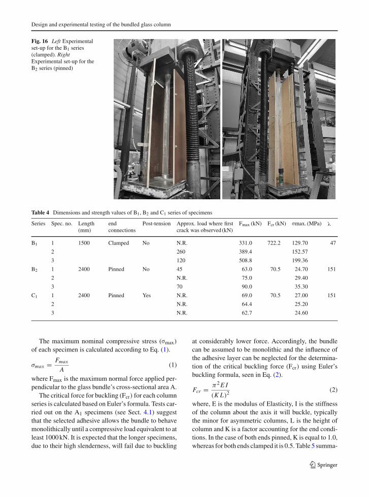
Fig. 16 Left Experimentalset-up for the B1 series(clamped). RightExperimental set-up for theB2 series (pinned)
Table 4 Dimensions and strength values of B1, B2 and C1 series of specimens
Series Spec. no. Length(mm)
endconnections
Post-tension Approx. load where firstcrack was observed (kN)
Fmax (kN) Fcr (kN) σmax. (MPa) λ
B1 1 1500 Clamped No N.R. 331.0 722.2 129.70 47
2 260 389.4 152.57
3 120 508.8 199.36
B2 1 2400 Pinned No 45 63.0 70.5 24.70 151
2 N.R. 75.0 29.40
3 70 90.0 35.30
C1 1 2400 Pinned Yes N.R. 69.0 70.5 27.00 151
2 N.R. 64.4 25.20
3 N.R. 62.7 24.60
The maximum nominal compressive stress (σmax)
of each specimen is calculated according to Eq. (1).
σmax = Fmax
A(1)
where Fmax is the maximum normal force applied per-pendicular to the glass bundle’s cross-sectional area A.
The critical force for buckling (Fcr) for each columnseries is calculated based on Euler’s formula. Tests car-ried out on the A1 specimens (see Sect. 4.1) suggestthat the selected adhesive allows the bundle to behavemonolithically until a compressive load equivalent to atleast 1000kN. It is expected that the longer specimens,due to their high slenderness, will fail due to buckling
at considerably lower force. Accordingly, the bundlecan be assumed to be monolithic and the influence ofthe adhesive layer can be neglected for the determina-tion of the critical buckling force (Fcr) using Euler’sbuckling formula, seen in Eq. (2).
Fcr = π2E I
(K L)2(2)
where, E is the modulus of Elasticity, I is the stiffnessof the column about the axis it will buckle, typicallythe minor for asymmetric columns, L is the height ofcolumn and K is a factor accounting for the end condi-tions. In the case of both ends pinned, K is equal to 1.0,whereas for both ends clamped it is 0.5. Table 5 summa-
123
F. Oikonomopoulou et al.
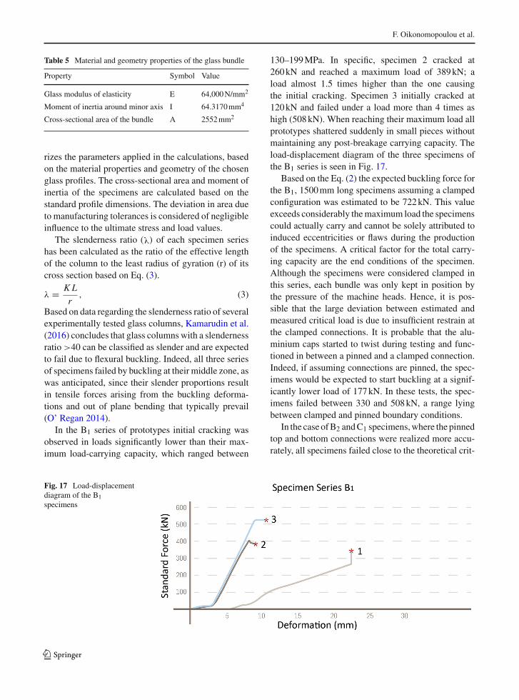
Table 5 Material and geometry properties of the glass bundle
Property Symbol Value
Glass modulus of elasticity E 64,000N/mm2
Moment of inertia around minor axis I 64.3170mm4
Cross-sectional area of the bundle A 2552mm2
rizes the parameters applied in the calculations, basedon the material properties and geometry of the chosenglass profiles. The cross-sectional area and moment ofinertia of the specimens are calculated based on thestandard profile dimensions. The deviation in area dueto manufacturing tolerances is considered of negligibleinfluence to the ultimate stress and load values.
The slenderness ratio (λ) of each specimen serieshas been calculated as the ratio of the effective lengthof the column to the least radius of gyration (r) of itscross section based on Eq. (3).
λ = K L
r, (3)
Based on data regarding the slenderness ratio of severalexperimentally tested glass columns, Kamarudin et al.(2016) concludes that glass columnswith a slendernessratio >40 can be classified as slender and are expectedto fail due to flexural buckling. Indeed, all three seriesof specimens failed by buckling at their middle zone, aswas anticipated, since their slender proportions resultin tensile forces arising from the buckling deforma-tions and out of plane bending that typically prevail(O’ Regan 2014).
In the B1 series of prototypes initial cracking wasobserved in loads significantly lower than their max-imum load-carrying capacity, which ranged between
130–199MPa. In specific, specimen 2 cracked at260kN and reached a maximum load of 389kN; aload almost 1.5 times higher than the one causingthe initial cracking. Specimen 3 initially cracked at120kN and failed under a load more than 4 times ashigh (508kN). When reaching their maximum load allprototypes shattered suddenly in small pieces withoutmaintaining any post-breakage carrying capacity. Theload-displacement diagram of the three specimens ofthe B1 series is seen in Fig. 17.
Based on the Eq. (2) the expected buckling force forthe B1, 1500mm long specimens assuming a clampedconfiguration was estimated to be 722kN. This valueexceeds considerably themaximum load the specimenscould actually carry and cannot be solely attributed toinduced eccentricities or flaws during the productionof the specimens. A critical factor for the total carry-ing capacity are the end conditions of the specimen.Although the specimens were considered clamped inthis series, each bundle was only kept in position bythe pressure of the machine heads. Hence, it is pos-sible that the large deviation between estimated andmeasured critical load is due to insufficient restrain atthe clamped connections. It is probable that the alu-minium caps started to twist during testing and func-tioned in between a pinned and a clamped connection.Indeed, if assuming connections are pinned, the spec-imens would be expected to start buckling at a signif-icantly lower load of 177kN. In these tests, the spec-imens failed between 330 and 508kN, a range lyingbetween clamped and pinned boundary conditions.
In the case ofB2 andC1 specimens,where the pinnedtop and bottom connections were realized more accu-rately, all specimens failed close to the theoretical crit-
Fig. 17 Load-displacementdiagram of the B1specimens
123
Design and experimental testing of the bundled glass column
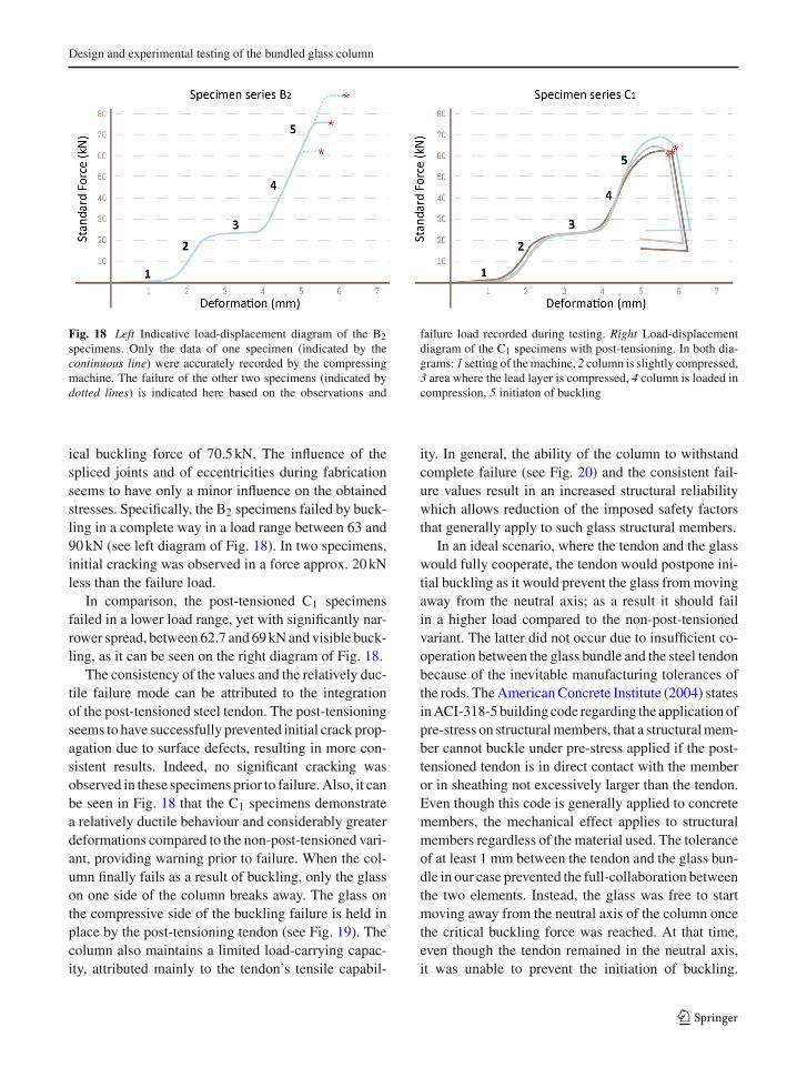
Fig. 18 Left Indicative load-displacement diagram of the B2specimens. Only the data of one specimen (indicated by thecontinuous line) were accurately recorded by the compressingmachine. The failure of the other two specimens (indicated bydotted lines) is indicated here based on the observations and
failure load recorded during testing. Right Load-displacementdiagram of the C1 specimens with post-tensioning. In both dia-grams: 1 setting of themachine, 2 column is slightly compressed,3 area where the lead layer is compressed, 4 column is loaded incompression, 5 initiaton of buckling
ical buckling force of 70.5kN. The influence of thespliced joints and of eccentricities during fabricationseems to have only a minor influence on the obtainedstresses. Specifically, the B2 specimens failed by buck-ling in a complete way in a load range between 63 and90kN (see left diagram of Fig. 18). In two specimens,initial cracking was observed in a force approx. 20kNless than the failure load.
In comparison, the post-tensioned C1 specimensfailed in a lower load range, yet with significantly nar-rower spread, between 62.7 and 69kNand visible buck-ling, as it can be seen on the right diagram of Fig. 18.
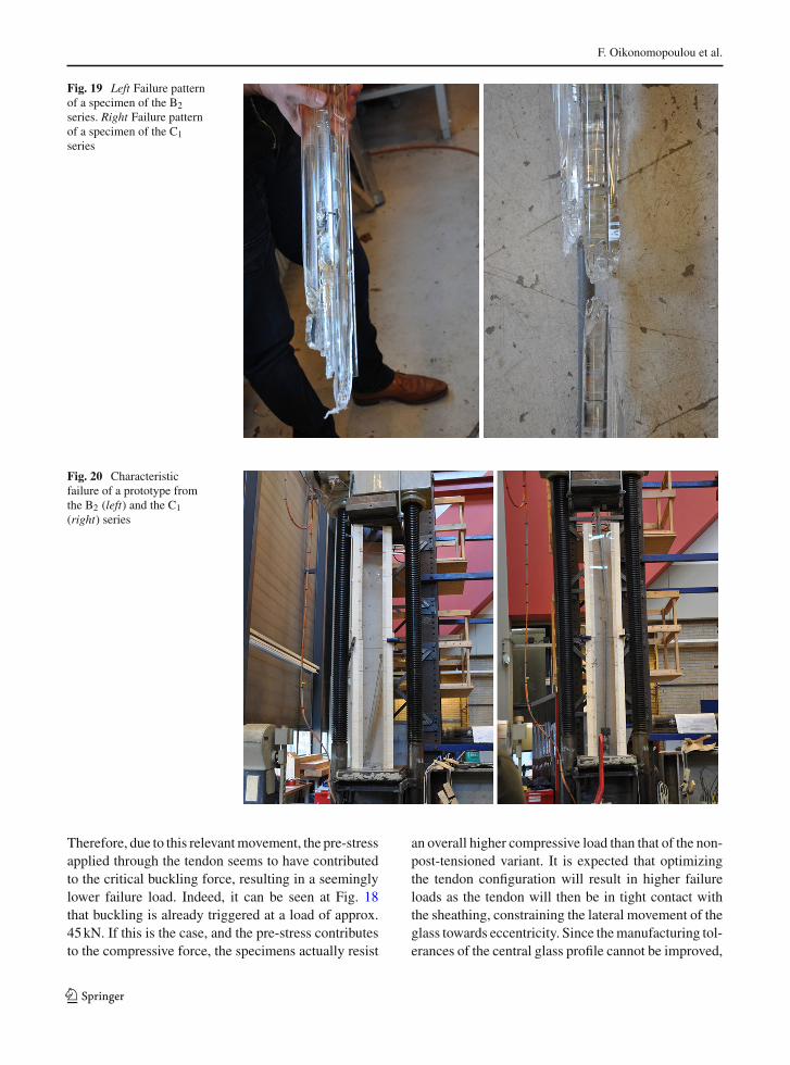
The consistency of the values and the relatively duc-tile failure mode can be attributed to the integrationof the post-tensioned steel tendon. The post-tensioningseems to have successfully prevented initial crack prop-agation due to surface defects, resulting in more con-sistent results. Indeed, no significant cracking wasobserved in these specimens prior to failure.Also, it canbe seen in Fig. 18 that the C1 specimens demonstratea relatively ductile behaviour and considerably greaterdeformations compared to the non-post-tensioned vari-ant, providing warning prior to failure. When the col-umn finally fails as a result of buckling, only the glasson one side of the column breaks away. The glass onthe compressive side of the buckling failure is held inplace by the post-tensioning tendon (see Fig. 19). Thecolumn also maintains a limited load-carrying capac-ity, attributed mainly to the tendon’s tensile capabil-
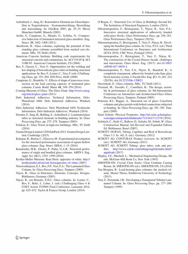
ity. In general, the ability of the column to withstandcomplete failure (see Fig. 20) and the consistent fail-ure values result in an increased structural reliabilitywhich allows reduction of the imposed safety factorsthat generally apply to such glass structural members.
In an ideal scenario, where the tendon and the glasswould fully cooperate, the tendon would postpone ini-tial buckling as it would prevent the glass frommovingaway from the neutral axis; as a result it should failin a higher load compared to the non-post-tensionedvariant. The latter did not occur due to insufficient co-operation between the glass bundle and the steel tendonbecause of the inevitable manufacturing tolerances ofthe rods. TheAmericanConcrete Institute (2004) statesinACI-318-5building code regarding the applicationofpre-stress on structuralmembers, that a structuralmem-ber cannot buckle under pre-stress applied if the post-tensioned tendon is in direct contact with the memberor in sheathing not excessively larger than the tendon.Even though this code is generally applied to concretemembers, the mechanical effect applies to structuralmembers regardless of the material used. The toleranceof at least 1 mm between the tendon and the glass bun-dle in our case prevented the full-collaboration betweenthe two elements. Instead, the glass was free to startmoving away from the neutral axis of the column oncethe critical buckling force was reached. At that time,even though the tendon remained in the neutral axis,it was unable to prevent the initiation of buckling.
123
F. Oikonomopoulou et al.
Fig. 19 Left Failure patternof a specimen of the B2series. Right Failure patternof a specimen of the C1series
Fig. 20 Characteristicfailure of a prototype fromthe B2 (left) and the C1(right) series
Therefore, due to this relevantmovement, the pre-stressapplied through the tendon seems to have contributedto the critical buckling force, resulting in a seeminglylower failure load. Indeed, it can be seen at Fig. 18that buckling is already triggered at a load of approx.45kN. If this is the case, and the pre-stress contributesto the compressive force, the specimens actually resist
an overall higher compressive load than that of the non-post-tensioned variant. It is expected that optimizingthe tendon configuration will result in higher failureloads as the tendon will then be in tight contact withthe sheathing, constraining the lateral movement of theglass towards eccentricity. Since themanufacturing tol-erances of the central glass profile cannot be improved,
123

Design and experimental testing of the bundled glass column
the application of a heat shrink plastic tube of sufficientstiffness prior to the assembly and post-tensioning ona tendon of the closest diameter to the glass profilehole can significantly contribute to the cooperation ofthe different components of the column. In this way,the overall tolerance between the glass and the plastic-coated tendon can be confined to a few decimals of amillimetre.
7 Conclusions and discussion
A completely transparent, bundled glass column hasbeen developed and physically tested towards the eval-uation of its feasibility. The results indicate that thebundled glass column can be an elegant solution ofsufficient compressive strength in the search of a trans-parent, load-bearing component.
The experimental data from the compressive test-ing of small-scale specimens suggest that the describedbundled column behaves monolithically under loadingwhen the selected adhesive is applied. The consistenthigh failure stresses of these specimens indicate that thesoft lead interlayer can eliminate the effect of inducedimperfections in the contact surface as well.
The latter also highlights the importance of properdetailing of the column’s top and bottom connec-tions for the estimation of the corresponding ultimatestresses. The load-carrying capacity of the specimenseries B2 andC1 using accurately designed pinned con-nections proved to be within close proximity of theexpected theoretical critical buckling force, assuminga monolithic glass bundle. In comparison, the carry-ing capacity of the B1 specimens that were clampedto the machine only by friction resulted in a criticalforce corresponding to a column configuration betweena clamped and pinned situation.
Fluctuations of the load, variability of the mate-rial properties, eccentricities caused during produc-tion and uncertainties regarding the analytical mod-els all contribute to lowering the probability of flaw-less behaviour. Still, the effect of the spliced jointsusing aluminium discs seems to have little influenceon the final results. The performance could be furtherenhanced by applying monolithic rods of the desiredlength, or by forming longer members by weldingthe borosilicate rods together. Experimental testing ofwelded borosilicate rods by Bos et al. (2008) suggeststhat the reliability of glass welds is comparable to that
of the main material and that the presence of a welddoes not influence the specimen’s strength.
Apart from the A1 and A2 series that were restrictedto lengths of max. 500mm, all other tested speci-mens failed by buckling. Specimens of the B2 and C1
series (2400mm long) failed in load values close to theexpected critical force byEuler’s formula. TheC1 spec-imens, where post-tensioning was applied, presented amore consistent failure and a narrow load spread. Yet,post-tensioning of the column requires a very precise fitof the tendon to the glass component to increase the car-rying capacity of the specimens. Still, the consistent andvisible buckling failure, as well as the improved post-breakage behaviour of the column can greatly reducethe imposed safety factors. In this direction, the steeltendon can also be designed and engineered to providean alternative, built-in load path that can reduce theconsequences of failure.
Further work will focus on the development of thetop and bottom connections as well as on increasingthe safety of the column. For this, the effect of post-tensioning will be further explored and a series ofexperiments will be conducted to explore in detail thecolumn’s performance.
The presented glass column design will be firstapplied in the truss elements of a temporary pedestrian14m long bridge at the TU Delft campus.
Acknowledgements Theauthors gratefully acknowledgeKeesBaardolf for his technical assistance and remarkable insight inthe manufacturing of the prototypes, Dr. ir. Christian Louterfor his valuable feedback and Fred Schilperoort for operatingthe hydraylic machines used to carry out the experiments. Theauthors also express their gratitude to Spyros Oikonomopoulosfor his valuable engineering feedback.
Compliance with ethical standards
Conflicts of interest On behalf of all authors, the correspondingauthor states that there is no conflict of interest.
Open Access This article is distributed under the terms ofthe Creative Commons Attribution 4.0 International License(http://creativecommons.org/licenses/by/4.0/), which permitsunrestricted use, distribution, and reproduction in any medium,provided you give appropriate credit to the original author(s) andthe source, provide a link to the Creative Commons license, andindicate if changes were made.
References
Achenbach, J., Behling, S., Doenitz, F.: Konstruktive Elementenaus Glasrohrprofilen. Glas Archit. Tech. 5, 5–10 (2002)
123
F. Oikonomopoulou et al.
Achenbach, J., Jung, H.: Konstruktive Element aus Glasrohrpro-filen in Tragstrukturen - Systementwicklung, Herstellungand Anwendung. In: GlasKon 2003, pp. 29–34. MesseMunchen GmbH, Munich (2003)
Aiello, S., Campione, G., Minafo, G., Scibilia, N.: Compres-sive behaviour of laminated structural glass members. Eng.Struct. 33, 3402–3408 (2011)
Akerboom, R.: Glass columns, exploring the potential of freestanding glass columns assembled from stacked cast ele-ments. MSc, TU Delft (2016)
American Concrete Institute: Building code requirements forstructural concrete and commentary. In: ACI 318-05 &ACI318R-05. American Concrete Institute, US (2004)
Bos, F., Giezen, C., Veer, F.: Opportunities for the welding andhot-shaping of borosilicate glass tubes in building structuralapplications. In: Bos, F., Louter, C., Veer, F. (eds.) Challeng-ing Glass, pp. 193–204. IOS Press, Delft (2008)
Campione, G., Rondello, V.: Effects of shape of transverse cross-section on the load carrying capacity of laminated glasscolumns. Constr. Build. Mater. 61, 349–359 (2014)
Corning Museum of Glass: The Glass Giant. http://www.cmog.org/article/glass-giant (2011)
Delo Industrial Adhesives: Technical Information. Delo-Photobond 4468. Delo Industrial Adhesives, Windach(2014)
Delo Industrial Adhesives: Delo Photobond 4494 TechnischeInformation. Delo Industrial Adhesives, Windach (2016)
Doenitz, F., Jung,H.,Behling, S.,Achenbach, J.: Laminated glasstubes as structural elements in building industry. In: GlassProcessing Days, pp. 275–278. Tampere (2003)
Felekou, E.: Glass Tower in high-rise buildings. MSc, TU Delft(2016)
GrantaDesignLimited: CESEduPack 2015.GrantaDesignLim-ited, Cambridge (2015)
Kalamar,R., Bedon,C., Eliasova,M.: Experimental investigationfor the structural performance assessment of square hollowglass columns. Eng. Struct. 113(4), 1–15 (2016)
Kamarudin, M.K., Disney, P., Parke, G.A.R.: Structural perfor-mance of single and bundled glass columns. ARPN J. Eng.Appl. Sci. 11(3), 1593–1599 (2016)
Kroller-Muller Museum: Roni Horn: opposites of white. http://krollermuller.nl/en/roni-hornopposites-of-white (2007)
Nieuwenhuijzen, E.J., Bos, F.P., Veer, F.A.: The LaminatedGlassColumn. In: Glass Processing Days, Tampere (2005)
Nijsse, R.: Glass in Structures: Elements, Concepts, Designs.Birkhauser, Germany (2003)
Nijsse, R., ten Brincke, E.H.J.: Glass columns. In: Louter, C.,Bos, F., Belis, J., Lebet, J. (eds.) Challenging Glass 4 &COST Action TU0905 Final Conference, Lausanne 2014,pp. 625–632. Taylor & Francis Group, London (2014)
O’Regan, C.: Structural Use of Glass in Buildings Second Ed.The Institution of Structural Engineers, London (2014)
Oikonomopoulou, F., Bristogianni, T., Nijsse, R., Veer, F.A.:Innovative structural applications of adhesively bondedsolid glass blocks. Glass Performance Days, pp. 256–261.Glass Performance Days, Tampere (2015a)
Oikonomopoulou, F., Bristogianni, T., Veer, F., Nijsse, R.: Devel-oping the bundled glass column. In: Cruz, P.J.S. (ed.) ThirdInternational Conference on Structures and Architecture(ICSA 2016). CRC Press, Portugal (2016)
Oikonomopoulou, F., Bristogianni, T., Veer, F., Nijsse, R.:The construction of the Crystal Houses facade: challengesand innovations. Glass Struct. Eng. (2017). doi:10.1007/s40940-017-0039-4
Oikonomopoulou, F., Veer, F.A., Nijsse, R., Baardolf, K.: Acompletely transparent, adhesively bonded soda-lime glassblockmasonry system. J. FacadeDes. Eng. 2(3–4), 201–222(2015b). doi:10.3233/fde-150021
Ouwerkerk, E.: Glass columns. MSc, TU Delft (2011)Overend, M., Vassallo, C., Camillieri, K.: The design, assem-
bly & performance of glass columns. In: 9th InternationalConference on Automotive and Architectural Glass (GlassProcessing Days), Tampere, Finland (2005)
Petersen, R.I., Bagger, A.: Structural use of glass: Cruciformcolumns and glass portalswith bolted connections subjectedto bending. In: Glass Processing Days, pp. 381–385. Tam-pere (2009)
Saint Gobain: Physical Properties. http://uk.saint-gobainglass.com/appcommportalchilddetails/713/442/711/378 (2016)
Schittich,C., Staib,G.,Balkow,D., Schuler,M., Sobek,W.:GlassConstruction Manual 2nd Revised and Expanded EditionEd. Birkhauser, Basel (2007)
SCHOTT: DURAN, Tubing, Capillary and Rod of BorosilicateGlass 3.3. In: AG, S. (ed.). Germany (2012)
SCHOTT AG: CONTURAX Product overview. In: SCHOTT(ed.). SCHOTT AG, Germany (2013)
SCHOTT AG: SCHOTT Tubing: glass tubes, rods and pro-files. http://www.schott.com/tubing/english/index.html?appid=ph (2017)
Shigley, J.E., Mitchell, L.: Mechanical Engineering Design, 4thedn. McGraw-Hill Book Co, New York (1993)
SMOOTH-ON: Crystal Clear Series: Clear Urethane CastingResins. In: SMOOTH-ON (ed.). SMOOTH-ON, US (2016)
Van Heugten, R.: Load-bearing glass columns: the stacked col-umn. Master Thesis, Eindhoven University of Technology(2013)
Veer, F., Pastunink, J.R.: Developing a Transparent Tubular Lam-inated Column. In: Glass Processing Days, pp. 277–280.Tampere (1999)
123