Design and evaluation of a cantilever beam-type prosthetic foot for ...
97
Design and Evaluation of a Cantilever Beam-Type Prosthetic Foot for Indian Persons with Amputations by M Kathryn M. Olesnavage B.S. Mechanical Engineering Massachusetts Institute of Technology, 2012 Submitted to the Department of Mechanical Engineering ASSACHUSETTS INSTrflJTE OF TECHNOLOGY AUG 15 2014 Li RARI ES AqCH$Eg in partial fulfillment of the requirements for the degree of Master of Science in Mechanical Engineering at the MASSACHUSETTS INSTITUTE OF TECHNOLOGY June 2014 @ Massachusetts Institute of Technology 2014. All rights reserved. Signature redacted A uthor .................... ..... Department of Mechanical Engineering May 9, 2014 Certified by............... Signature redacted e Amos G. Winter, V Assistant Professor of Mechanical Engineering Z Thesi& Supervisor Signature redacted A ccepted by ................... ........... David E. Hardt Professor of Mechanical Engineering Graduate Officer 0
Transcript of Design and evaluation of a cantilever beam-type prosthetic foot for ...

Design and Evaluation of a Cantilever Beam-Type
Prosthetic Foot for Indian Persons with Amputations
by M
Kathryn M. Olesnavage
B.S. Mechanical EngineeringMassachusetts Institute of Technology, 2012
Submitted to the Department of Mechanical Engineering
ASSACHUSETTS INSTrflJTEOF TECHNOLOGY
AUG 15 2014
Li RARI ES
AqCH$Eg
in partial fulfillment of the requirements for the degree of
Master of Science in Mechanical Engineering
at the
MASSACHUSETTS INSTITUTE OF TECHNOLOGY
June 2014
@ Massachusetts Institute of Technology 2014. All rights reserved.
Signature redactedA uthor .................... .....
Department of Mechanical EngineeringMay 9, 2014
Certified by............... Signature redactede Amos G. Winter, V
Assistant Professor of Mechanical EngineeringZ Thesi& Supervisor
Signature redactedA ccepted by ................... ...........
David E. HardtProfessor of Mechanical Engineering
Graduate Officer
0


Design and Evaluation of a Cantilever Beam-Type Prosthetic
Foot for Indian Persons with Amputations
by
Kathryn M. Olesnavage
Submitted to the Department of Mechanical Engineeringon May 9, 2014, in partial fulfillment of the
requirements for the degree ofMaster of Science in Mechanical Engineering
Abstract
The goal of this work is to design a low cost, high performance prosthetic foot in col-laboration with Bhagwan Mahaveer Viklang Sahayata Samiti (BMVSS), in Jaipur,India. In order to be adopted, the foot must cost less than $10 USD, be mass-manufacturable, and meet or exceed the performance of the Jaipur Foot, BMVSS'current prosthetic foot. This thesis investigates different metrics that are used todesign and evaluate prosthetic feet and presents an analysis and evaluation of a solidankle, cantilever beam - type prosthetic foot.
Methods of comparing prosthetic feet in industry and in academia are discussed us-ing a review of literature. These comparisons can be categorized into mechanical,metabolic, subjective, and gait analysis comparisons. The mechanical parameters arethe most useful for designing a new prosthetic foot, as they are readily translated intoengineering design requirements; however, these are the furthest removed from theperformance of the foot. On the other end of the spectrum are metabolic and subjec-tive parameters, which are useful in evaluating prosthetic feet because the objectivesof minimizing energy expenditure and earning user approval are clear. Somewherebetween these is gait analysis. The literature review reveals that not enough infor-mation is available to bridge these categories, that is, there is no consensus on howany particular mechanical parameter affects the subjective ranking of a prostheticfoot. Two mechanical parameters emerge as necessary, but not sufficient: the roll-over shape and the energy storage and return capacity of a prosthetic foot.
A simple model of a solid ankle, cantilever beam - type prosthetic foot is analyzedin the context of these two parameters. By applying beam bending theory and pub-lished gait analysis data, it is found that an unconstrained cantilever beam maximizesenergy storage and return, but does not replicate a physiological roll-over shape wellregardless of bending stiffness. Finite element analysis is used to find the roll-overshape and energy storage capacity from the same model when a mechanical constraintis added to prevent over deflection. The results show that for very compliant beams,
3

the roll-over shape is nearly identical to the physiological rollover shape, but the en-ergy storage capacity is low. For stiff beams, the opposite is true. Thus there is atrade-off between roll-over shape and energy storage capacity for cantilever beam -type feet that fit this model. Further information is required to determine the relativeimportance of each of these parameters before an optimal bending stiffness can befound.
A proof-of-concept prototype was built according to this model and tested in In-dia at BMVSS. It was found that another parameter - perception of stability, whichis perhaps dependent on the rate of forward progression of the center of pressure -is equally important as, if not more than, the other parameters investigated here.Perception of stability increased with bending stiffness. The prototype foot receivedmixed feedback and has potential to be further refined. However, the solid anklemodel is inappropriate for persons living in India, as it does not allow enough truedorsiflexion to permit squatting, an important activity that is done many times aday in the target demographic. Future work will use a similar method to design andoptimize a prosthetic foot with a rotational ankle joint to allow this motion.
Thesis Supervisor: Amos G. Winter, VTitle: Assistant Professor of Mechanical Engineering
4

Acknowledgments
I would like to thank the following people, all of whom were instrumental in the
completion of this thesis:
* My family, for their love and support
" Prof. Amos Winter, for pushing me to achieve things I thought impossible and
for giving me the freedom to pursue my own interests
* Mr. Mehta, Dr. Mathur, Dr. Pooja Mukul, Rajendra and Jitendra at BMVSS,
for taking the time out of their busy schedules to facilitate this project
" Namita Sharma, for her help translating and for making me feel at home in
India
" Paul Suresh, for making sure I didn't miss out on a single opportunity to try
new food and for never giving up in his quest to teach me to speak Hindi
* My labmates, for always being there for me as sounding boards and for never
failing to have my back
" My friends and roommates, for never letting me go too long without laughing
* Dr. Rob Stoner, Prof. Charlie Fine, Dr. Nevan Hanumara, Dr.
Vaishnav and the Tata Center for making this work possible
9 All of the people I have met and interacted with in India, at BMVSS and
elsewhere
I am also greatly appreciative to the following programs, without whom this work
would not have been possible:
Ida M Green Fellowship
Tata Center for Technology and Design
MIT India Innovation Fund
5
Chintan

6

Contents
1 Introduction
1.1 Typical Human Gait and Biomechanics . . . . . . . . . . . . . . . . .
1.2 Preliminary Interactions with People Using Jaipur Limbs . . . . . . .
1.3 Design Requirements for New Prosthetic Foot . . . . . . . . . . . . .
1.4 Outline of Thesis . . . . . . . . . . . . . . . . . . . . . . . . . . . . .
2 Evaluating and Measuring Prosthetic Foot Performance
2.1 Introduction . . . . . . . . . . . . . . . . . . . . . . . . . . . . . . . .
2.2 Prosthetic Foot Comparisons In Industry . . . . . . . . . . . . . . . .
2.2.1 American Orthotic and Prosthetic Association Prosthetic Foot
P roject . . . . . . . . . . . . . . . . . . . .
2.2.2 ISO 22675 . . . . . . . . . . . . . . . . . .
2.3 Prosthetic Foot Comparisons in Academia . . . .
2.3.1 M ethod . . . . . . . . . . . . . . . . . . .
2.3.2 Results and Discussion . . . . . . . . . . .
2.4 D iscussion . . . . . . . . . . . . . . . . . . . . . .
2.5 Conclusion . . . . . . . . . . . . . . . . . . . . . .
3 Theoretical Considerations for a Mechanically
tilever Beam - Type Foot
3.1 Introduction . . . . . . . . . . . . . . . . . . . . .
3.2 Unconstrained Cantilever Beam Model . . . . . .
3.3 Constrained Cantilever Beam . . . . . . . . . . .
. . . . . . . . . . . 32
. . . . . . . . . . . 34
. . . . . . . . . . . 35
. . . . . . . . . . . 35
. . . . . . . . . . . 36
. . . . . . .. . . . . 48
. . . . . . . . . . . 5 1
Constrained Can-
59
59
65
68
7
13
15
20
24
24
31
31
32

3.3.1 Finite Element M odel . . . . . . . . . . . . . . . . . . . . . . 70
3.3.2 M ethod . . . . . . . . . . . . . . . . . . . . . . . . . . . . . . 70
3.3.3 Results. . . . . . . . . . . . . . . . . . . . . . . . . . . . . . . 76
3.4 Discussion . . . . . . . . . . . . . . . . . . . . . . . . . . . . . . . . . 77
3.5 Prototype Testing . . . . . . . . . . . . . . . . . . . . . . . . . . . . . 83
3.5.1 M ethod . . . . . . . . . . . . . . . . . . . . . . . . . . . . . . 84
3.5.2 Results and Discussion . . . . . . . . . . . . . . . . . . . . . . 85
3.6 Conclusion . . . . . . . . . . . . . . . . . . . . . . . . . . . . . . . . . 86
4 Conclusion 95
8

List of Figures
1-1 Internal Cross-Section of a Jaipur Foot . . . . . . . . . . . . . . . . . 14
1-2 Anatomical Reference Planes . . . . . . . . . . . . . . . . . . . . . . . 16
1-3 Ankle Plantar and Dorsiflexion . . . . . . . . . . . . . . . . . . . . . 17
1-4 Ankle/Foot Anatomical Terms of Location . . . . . . . . . . . . . . . 18
1-5 Power Output at Ankle During Typical Gait Cycle . . . . . . . . . . 20
1-6 The roll-over shape of a foot . . . . . . . . . . . . . . . . . . . . . . . 21
1-7 Semi-structured interview responses for ease and importance of various
activities . . . . . . . . . . . . . . . . . . . . . . . . . . . . . . . . . . 23
3-1 Transition from gait analysis parameters to beam bending parameters 65
3-2 Hypothetical force versus displacement curve for cantilever beam . . . 67
3-3 Analytical roll-over shapes for unconstrained cantilever beams with
uniform cross-section for various bending stiffnesses . . . . . . . . . . 68
3-4 Force versus displacement curves for cantilever beams that are too
compliant, too stiff, and ideal . . . . . . . . . . . . . . . . . . . . . . 69
3-5 FE model of constrained cantilever beam foot . . . . . . . . . . . . . 71
3-6 Calculating roll-over shape from FEA results . . . . . . . . . . . . . . 73
3-7 Roll-over shape results from FEA of constrained cantilever beams of
various bending stiffnesses . . . . . . . . . . . . . . . . . . . . . . . . 76
3-8 Force versus deflection curves resulting from FEA of constrained can-
tilever beams of various bending stiffnesses . . . . . . . . . . . . . . . 78
3-9 Trade-off between roll-over shape and energy storage capacity for con-
strained cantilever beams of various bending stiffnesses . . . . . . . . 79
9

3-10 Implications for energy storage capacity for hypothetical foot that en-
gages second cantilever beam in late stance . . . . . . . . . . . . . . . 82
3-11 Subject taking a step with the proof-of-concept prototype prosthetic
foot at BMVSS headquarters in Jaipur . . . . . . . . . . . . . . . . . 86
10

List of Tables
1.1 Phases of Gait Cycle [18] . . . . . . . . . . . . . . . . . . . . . . . . . 18
1.2 Demographic information for semi-structured interview participants . 22
1.3 Design requirements for prosthetic foot . . . . . . . . . . . . . . . . . 25
2.1 Search criteria used in Compendex Database and Inspec Database . . 36
2.2 Description of metrics, test setup and feet investigated in mechanical
foot comparison studies . . . . . . . . . . . . . . . . . . . . . . . . . . 38
2.3 Outcomes of studies using mechanical metrics to compare prosthetic feet 39
2.4 Descriptions and outcomes of studies using subjective comparisons of
prosthetic feet . . . . . . . . . . . . . . . . . . . . . . . . . . . . . . . 42
2.5 Descriptions of studies using metabolic parameters to compare pros-
thetic feet . . . . . . . . . . . . . . . . . . . . . . . . . . . . . . . . . 42
2.6 Outcomes of studies using metabolic parameters to compare prosthetic
feet . . . . . . . . . . . . . . . . . . . . . . . . . . . . . . . . . . . . . 4 3
2.7 Outcomes of studies using gait analysis to compare prosthetic feet . . 46
3.1 Example of effects of material choice on cantilever beam for range of
bending stiffnesses investigated herein . . . . . . . . . . . . . . . . . . 80
11

12
Chapter 1
Introduction
Bhagwan Mahaveer Viklang Sahayata Samiti (BMVSS), an NGO headquartered in
Jaipur, India, is the largest organization serving persons with disabilities in the world
[3]. Since its inception in 1975, BMVSS has fitted and/or distributed more than 1.3
million prosthetic limbs. In 2013, they provided over 24,000 limbs. The organization
is sustained entirely through donations and government subsidies - all of the limbs
and other assistive devices are supplied free of charge to people in need. This ser-
vice is much needed; according to a report by the Indian Ministry of Statistics and
Programme Implementation, published in 2003, 1,008 out of every 100,000 people
in India have a locomotor disability, and 77 out of every 1,000 of those locomotor
disabilities are due to loss of limb [15]. Based on these survey results, 0.08% of the
population, or nearly 960,000 people are missing some part of a lower limb [4]. The
global prosthetics market as a whole is expected to reach US$23.5 billion by 2017 [6].
The most widely known product from BMVSS is a prosthetic foot called the Jaipur
Foot - in fact, the organization itself is commonly referred to as Jaipur Foot. The
foot was developed in Jaipur in 1968 in response to the SACH foot - or Solid Ankle,
Cushioned Heel foot - failing to suit the specific needs of Indian persons with am-
putations [21]. Unlike the SACH foot, which has a rigid keel, or internal structure,
the Jaipur Foot allows users to squat, sit cross-legged, walk through mud and over
rough terrain. The Jaipur Foot also mimics the appearance of a biological foot and
13

Figure 1-1: Internal Cross-Section of a Jaipur Foot
is designed to be used either barefoot or with shoes.
The Jaipur Foot is handmade from wood and several types of rubber, as shown
in Figure 1-1. Skilled technicians carve an ankle block from wood and a heel, fore-
foot, and toes from microcelluar rubber compounds. The heel, forefoot, and toes are
each coated in a vulcanizing cement, then wrapped with tire cord - a fiber-reinforced
rubber tape. Next, the ankle block, heel, forefoot, and toes are assembled using the
tire cord in a pattern mimicking the internal structure of a biological foot. The entire
foot is then wrapped in a skin-colored rubber, enclosed in a mold and pressurized in
an autoclave. Once removed, it is ready to be fixed to the rest of the prosthetic limb
and used. The foot costs approximately $5-$10 to fabricate.
In addition to being inexpensive and suitable for the needs of Indian persons with
amputations, the Jaipur foot is widely regarded as a relatively high performance pros-
thetic foot. A study that compared the Jaipur foot to the SACH foot and the Seattle
foot, a commercially available energy storing foot, using ground reaction forces found
that the Jaipur foot allowed the most natural gait and enabled users to most closely
replicated typical walkingf1]. In another study, the roll-over shape, or path of center
14

of pressure along the bottom of the foot (see Section 1.1 for more detailed description
of roll-over shape), was measured for eleven types of prosthetic feet used across the
developing world; of these, only the Jaipur Foot exhibited a circular roll-over shape,
which is closest to the physiological shape, albeit the radius was smaller, which is
likely due to increased dorsiflexion to allow squatting[19].
In 2002, BMVSS began working with the Indian Space Research Organization (ISRO)
to design a polyurethane (PU) version of the Jaipur Foot [8]. The resulting foot would
be lighter weight and mass-manufacturable, which is more efficient in terms of both
time and money, and would allow for more consistent quality. Several PU prototypes
have been made in collaboration with Dow Chemical, but none have matched the
durability of the original rubber Jaipur Foot.
The goal of this work is to design a mass-manufacturable prosthetic foot that performs
as well as, if not better than, the Jaipur Foot. In order to meet these difficult con-
straints, it is necessary that we fully understand the governing behavior of prosthetic
feet as well as the social factors that determine the design requirements.
1.1 Typical Human Gait and Biomechanics
Before any further discussion, several terms and parameters related to typical human
biomechanics must be defined. Throughout the course of this thesis, the adjective
"typical" will be used to describe anything pertaining to a person without amputation
or other impairment, e.g. typical gait.
Biomechanical Terms
The three planes which are most commonly used to describe anatomical motions are
the sagittal, coronal, and transverse planes, as shown in Figure 1-2. For the ankle
joint, the primary motion during flat ground walking occurs in the sagittal plane.
This motion is called dorsiflexion when the toes lift up toward the knee, and plantar
15

flexion when the toes point down away from the knee, as shown in Figure 1-3. The
reference axes and the anatomical terms of location for a foot-ankle system are shown
in Figure 1-4.
Sagittal PlaneCt naI PImno
Transverse Plane
KZZJ
Body Plames
Figure 1-2: Anatomical Reference Planes [20]
Typical Gait Cycle
The gait cycle covers one stride, or one complete sequence from the time one heel
makes contact with the ground to the next time that same heel makes contact with
the ground. There are many ways to break this cycle up into different phases. The
simplest division is stance phase and swing phase. Stance phase occurs when the foot
is in contact with the ground; the rest of the gait cycle is swing phase. Note that
when one foot is in swing phase, the contralateral foot is always in stance phase. Each
leg is in stance phase for about 60% of the gait cycle, and in swing phase the other
40%. This means that there is a period in time when both feet are in stance phase.
This is called double limb support, as opposed to single limb support. The gait cycle
16

Dorsiflexion
Plantar flexion
Figure 1-3: Ankle Plantar and Dorsiflexion[16]
is further broken down by Perry into eight different phases, described in Table 1.1.
Palmer and Gates provide a different set of phases to describe the same events: con-
trolled plantar flexion, controlled dorsiflexion, powered plantar flexion, and swing
phase [17, 5]. The definitions for these come from plotting the angle versus torque
curve for the ankle, which can be broken up into these four segments. In each of these
segments, the ankle exhibits a particular behavior, as described by the names of the
phases. These are very useful in designing powered prosthetic foot-ankle systems, as
sensors can be used to detect which of these phases the prosthesis is in at any given
time and alter the output of the ankle according [2]. In passive prostheses, these
phases are less useful, as the behavior of the prosthesis cannot be altered during gait.
Most passive prostheses focus only on mimicking the behavior of the ankle during
17

ial
Plantar
Figure 1-4: Ankle/Foot Anatomical Terms of Location
Table 1.1: Phases of Gait Cycle [181
Phase Functional PercentageTask of Gait
Cycle
Initial Double Initial Contact Weight 0% to 2%Limb Stance Loading Response Acceptance 2% to 12%
Single Limb Mid Stance Single Limb 12% to 31%Stance Phase Support Terminal Stance Support 31% to 50%
Terminal Pre-Swing 50% to 62%Double Limb
Support Swing Limb
Initial Swing Advancement 62% to 75%
Swing Phase Swing Mid Swing 75% to 87%Terminal Swing 87% to 100%
controlled plantar flexion and controlled dorsiflexion.
Two events that occur during the gait cycle that will be used frequently in this
work are heel strike and toe-off. Heel strike refers to the instant that the heel hits the
ground, and is usually the start of what is considered the gait cycle. Toe-off occurs
when the toe of the foot leaves the ground; this marks the transition from stance
phase to swing phase.
18

Ankle Power During Gait
A parameter that will be frequently discussed in prosthetic foot design is the energy
storage and return capacity of a prosthetic foot. In order to investigate the function
of this property, the mechanical energy provided by a biological ankle must be un-
derstood. A plot of the power output at the ankle during the gait cycle is shown in
Figure 1-5. The ankle does more positive work than negative work over the course of
the gait cycle, and therefore is a net generator. During early and mid stance, the ankle
absorbs energy. At push-off, there is a large burst of power that aids in transitioning
to the contralateral foot. During swing phase, the biological ankle does a negligible
amount of work in positioning the foot in preparation for heel strike. For the typical
gait cycle measured and published by Winter, the ankle did 26.3 J of positive work
and 4.9 J of negative work over the step for a subject of body mass 56.7 kg [23]. This
and all other gait data used in this thesis comes from Winter's Biomechanics and
Motor Control of Human Movement.
Roll-over Shape
Another recurrent parameter in prosthetic foot design is the roll-over shape. The roll-
over shape is defined as the path of the center of pressure along the bottom of a foot
from the time the heel hits the ground (heel strike) until heel strike on the opposite
foot. This path is then rotated from the lab reference frame into the ankle-knee based
reference frame, as shown in Figure 1-6. The concept of a roll-over shape builds on
pre-existing rocker or rigid cam models of prosthetic feet [7, 11, 22, 18, 12, 10, 9, 13].
The resulting shape is roughly circular with a radius of 0.3 times the leg length [13].
19

10 20 30 40 50 60 70 80 90 100Percentage of Gait Cycle
3ff
Stance Phase Swing Phase
Figure 1-5: Power output at ankle during typical gait cycle as measured by Winterfor a person of body mass 56.7 kg [23]. Green area represents positive work, red arearepresents negative work. The ankle did 26.3 J of positive work and 4.9 J of negativework during the gait cycle shown here.
1.2 Preliminary Interactions with People Using Jaipur
Limbs
In January 2012, 19 people were interviewed with the help of a translator as they
waited to receive limbs at BMVSS in Jaipur, India. Each participant provided in-
formed consent verbally in accordance with a COUHES approved protocol. The
participants were all persons with unilateral amputations. Demographic information
about the participants is provided in Table 1.2.
Given a list of activities, each subject was asked whether they were able to per-
form each activity with no difficulty, with some difficulty, or with great difficulty
20
300 -
250-
200-
150-
100-
50 -
C,
0
0CL
-50'0
'I I
0

* - Center of Pressure
Figure 1-6: Illustration of obtaining the roll-over shape of a foot. The roll-over shapeof a foot is defined as the path of the center of pressure along the foot from heelstrike to opposite foot heel strike, rotated from (a) the laboratory reference frame to(b) the ankle-knee reference frame. The roll-over shape (c) comes from following thiscenter of pressure through an entire step, and is shown here in red. The data used tocreate these plots comes from Winter's Biomechanics and Motor Control of HumanMovement [23].
and whether each activity was very important, somewhat important, or not at all
important. Thus the ease and importance of each activity was ranked from 0 (great
difficulty / not at all important) to 2 (no difficulty/ very important). The average ease
and importance ratings across all 19 subjects are given in Figure 1-7. The activities
are displayed starting with the easiest activity at the top down to the most difficult at
the bottom. The number of subjects that provided responses to the questions about
the ease of each activity are provided in the activity description, as some people did
not do all of the activities and thus could not answer.
21
a)
b)
c)

Table 1.2: Demographic information for semi-structured interview participants
19 participants, each with unilateral transtibial amputationand experience using Jaipur Limb
Age in Years Average: 32.8Standard Deviation: 15.2
Gender 18 Male, 1 Female
Reason for Amputation 17 Trauma, 1 Sepsis,1 Cancer
Years Using Prosthesis Average: 9.1Standard Deviation: 7.0
Urban/Rural Residence 5 Urban, 14 Rural
The general order of the activities is as could be expected; activities such as walking
indoors and walking outdoors on flat terrain were ranked easier than running, walking
in wet mud or water, and walking up or down hills. The importance of most activities
is less than or equal to the ease of those same activities, which suggests that these
activities did not present any issue for the persons using the Jaipur Foot. However,
a few of these activities, namely standing for long periods of time, carrying heavy
objects, sitting cross-legged and squatting, were ranked as important and difficult.
Upon further investigation and discussion with the Jaipur Foot users, most of these
are due to problems with the prosthesis as a whole, and cannot be addressed by a new
foot alone. Sitting cross-legged, squatting, and standing for long periods of time were
difficult primarily due to discomfort caused by the socket. A new foot does however
provide an opportunity to address difficulties in carrying heavy objects. Subjects
reported that carrying heavy objects - particularly uphill - is difficult as the foot gets
"stuck". It seems to the author that under the increased load, the foot dorsiflexes
more than preferred. As a result, the user must first unload the prosthetic limb by
lifting it straight up before he can proceed to move forward. It should be noted that
the Jaipur Foot provides a greater degree of dorsiflexion than many feet in order to
allow users to squat, so there may be a trade-off between the stiffness required to
carry heavy objects and the compliance required to squat.
Other activities participants reported doing without difficulty included caring for
22

Use public transportation (n=19)
Walk indoors (n=1 8)
Walk on soft mud or sand (n=18)
Drive a motorcycle (n=1 1)Walk outdoors on flat terrain (n=18)
Ride a bicycle (n=17)
Do household chores (n=1 1)
Go up/down stairs (n=19)
Swim (n=5)
Walk long distances (>1km) (n=18)
Walk on rough or uneven terrain (n=18)
Drive a car (n=6)
Stand for long periods of time (n=19)
Walk up/down hills (n=16)
Carry heavy objects (n=1 8)
Sit cross-legged (n=18)Squat (n=19)
Walk in wet mud/water (n=16)
Run (n=16)Ease of ActivityImportance of Activity
I I I I I I I J0 0.2 0.4 0.6 0.8 1 1.2 1.4 1.6 1.8 2
Average response on scale from 0 (difficult/unimportant) to 2 (easy/important)
Figure 1-7: Semi-structured interview responses for ease and importance of various
activities. Perception of ease of activities is generally as expected. Three activitiesstand out as being difficult and important: standing for long periods of time, sittingcross-legged, and squatting, and carrying heavy objects. While all of these presentpotential areas for improvement, standing for long periods of time, sitting cross-legged, and squatting were perceived as difficult due to socket discomfort rather thanthe prosthetic foot technology. A stiffer foot could improve users abilities to carryheavy objects, but this is in opposition to the increased ankle dorsiflexion requiredfor squatting.
children, playing cricket, and watering wheat plants in a field. Additional activities
that participants stated they would like to be able to do included running in races,
climbing electrical poles to return to a job held prior to amputation, driving an rick-
shaw, and general farming.
The majority of the complaints participants had were about the socket - several
complained of poor fit, pistoning, and discomfort, sweating, and chaffing due to the
fully enclosed socket in India's hot, humid environment. These subjects were at the
23

BMVSS facility in order to be fit with a new prosthesis, so it is possible that these
socket issues were mostly due to the subjects' residual limbs changing size and/or
shape since their last visit to the facility. The only areas for improvement suggested
by subjects about the foot were that it is slippery in muddy or wet conditions, and
that they wish it lasted longer. The Jaipur Foot lasts comparably long to feet used
in the western world, but it is the least durable of the components that make up a
prosthesis. Thus, most of the time when Jaipur Foot users return to BMVSS to get
a new limb, it is because the previous foot broke. Increasing the durability of the
foot would let the people using the Jaipur Foot go longer between limbs, which would
require fewer trips to BMVSS, which can take days. People have been known to lose
their jobs when taking time off to travel to BMVSS and receive a new limb, decrease
the frequency of these trips by increasing prosthetic foot durability will result in a
huge improvement.
1.3 Design Requirements for New Prosthetic Foot
Based on interaction with the leadership team at Jaipur Foot, interviews with per-
sons using Jaipur limbs, and a review of literature, a set of design requirements has
been elucidated in order for a new prosthetic foot to be a viable product. The design
requirements are as listed in Table 1.3 below. Several of these will be elaborated in
the body of this thesis.
1.4 Outline of Thesis
This thesis describes the work that lead to the design and testing of a preliminary
prototype. A literature review was used to determine what metrics can be used to
design and evaluate prosthetic feet. The literature review suggested that two metrics
are required to achieve symmetric and efficient gait: the roll-over shape and energy
24

Table 1.3: Design requirements for prosthetic foot
Requirement Measurable Parameter Explanation
Mass-Manufacturable Binary Improves consistency while decreasing cost and time requiredto produce each foot.
Durable Lasts 3 - 5 years in the field Requires patients to travel to BMVSS less frequently, whichin turn increases number of patients BMVSS can fit.
Light Weight < 0.8 kg Increases comfort, decreases energy required for walking [141.
Compatible with Global Passes ISO 22675 Provides assurance to potential BMVSS investors.Standards
Compatible with Global Can be attached via radial Allows organizations from across the world to adopt the JaipurProstheses wood screws, a center bolt, or Foot without changing their preferred socket technology.
a standard pyramid adapter
Allow Squatting > 30 0 dorsiflexion Permits users to use squat toilets, sit to eat, etc.
Biological Appearance Must fit in envelope of a Mitigates social stigma associated with disabilitiestypical foot; must have foam
cosmesis
Weather Proof Entire foot should be encased Allows foot to be submerged in water, used in rain, etc., inin a durable foam-like material accordance with needs of subjects.
High Performance Meets or exceeds Jaipur Foot Discussed in Chapter 2in terms of metabolic cost and
subjective ranking
storage and return. A simple model of a cantilever beam-type prosthetic foot was
created. The roll-over shape and energy storage and return capacity of such a foot
were calculated using beam bending theory and FEA. A prototype was built and
tested at BMVSS in Jaipur, India. An outline of the thesis is as follows:
Chapter 2: Evaluating and measuring prosthetic foot performance
Methods of quantifying differences between prosthetic feet, both in industry
and in academia, were reviewed in order to determine what metrics are useful
for a) designing and b) evaluating a prosthetic foot. Various categories of
types of measurements that can be made with prosthetic feet are described;
the merits and limitations of each are discussed. The implications of this
literature review for prosthetic foot designers are presented.
Chapter 3: Analysis and testing of a cantilever beam-type foot A
prosthetic foot is modeled simply as a cantilever beam fixed beneath a solid
ankle. Using published gait data and beam bending theory, the roll-over shape
of this foot is found over a range of beam bending stiffnesses. This reveals
that a rigid constraint is necessary to mimic a physiological roll-over shape. A
constraint is added to the model. Finite element analysis is used to
approximate the roll-over shape and energy storage capacity for this model;
trends emerge for each of these as the bending stiffness is varied. A
25

proof-of-concept prototype foot is built based on these models and tested in
the gait lab in BMVSS in Jaipur. Gait data and subjective feedback are
discussed.
Chapter 5: Conclusion The important results from the preceding chapters are
discussed. Future work is recommended based on the results found herein.
26

Bibliography
[1] A. P. Arya, A. Lees, H. Nirula, and L. Klenerman. A biomechanical comparison
of the SACH, Seattle and Jaipur feet using ground reaction forces. Prosthetics
and Orthotics International, 19:37-45, 1995.
[2] S. K. Au, H. Herr, J. Weber, and E. C. Martinez-Villalpando. Powered ankle-foot
prosthesis for the improvement of amputee ambulation. Conference proceedings
: ... Annual International Conference of the IEEE Engineering in Medicine and
Biology Society. IEEE Engineering in Medicine and Biology Society. Conference,
2007:3020-6, Jan. 2007.
[3] Bhagwan Mahaveer Viklang Sahayata Samiti. Jaipurfoot.org. http: //www.
jaipurfoot.org.
[4] CIA. The world factbook. http: //www. cia. gov/library/publicat ions/
the-world-f actbook/geos/in. html.
[5] D. H. Gates. Characterizing ankle function during stair ascent, descent, and
level walking for ankle prosthesis and orthosis design. Master's thesis, Boston
University, 2004.
[6] Global Industry Analysts Inc. Orthopedic prosthetics - a global strategic business
report. Technical report, Research and Markets, March 2012.
[7] A. H. Hansen, D. S. Childress, and E. H. Knox. Prosthetic foot rollaARover
shapes with implications for alignment of transaARtibial prostheses. Prosthetics
and Orthotics International, 24(3):205-215, Jan. 2000.
27

[8] Hindu Business Line Bureau. Rocket science for lighter 'jaipur foot'. www.
thehindubusinessline.in.
[9] M.-S. Ju. The modeling and simulation of constrained dynamical systems - with
application to human gait. PhD thesis, Case Western Reserve University, USA,
1986.
[10] M.-S. Ju and J. M. Mansour. Simulation of the double limb support phase of
human gait. Journal of Biomechanical Engineering, 110(3):223-9, Aug. 1988.
[11] E. H. Knox. The role of prosthetic feet in walking. PhD thesis, Northwestern
University, 1996.
[12] H. Koopman. The three-dimensional analysis and prediction of human walking.
PhD thesis, University of Twente, The Netherlands, 1989.
[131 T. McGeer. Passive Dynamic Walking. The International Journal of Robotics
Research, 9(2):62-82, Apr. 1990.
[14] Y. S. Narang. Identification of design requirements for a high-performance, low-
cost, passive prosthetic knee through user analysis and dynamic simulation. Mas-
ter's thesis, Massachusetts Institute of Technology, 2013.
[15] National Sample Survey Organization. Disabled Persons in India. Technical
Report 485, Ministry of Statistics and Programme Implementation, Government
of India, New Delhi, India, 2003.
[16] OpenStax College. Anatomy & physiology. Connexions Web Site. http: //cnx.
org/content/co111496/1.6/, June 19 2013.
[17] M. Palmer. Sagittal plane characterization of normal human ankle function
across a range of walking gait speeds. Master's thesis, Massachusetts Institute
of Technology, 2002.
[18] J. Perry and J. M. Burnfield. Gait Analysis: Normal and Pathological Function.
Slack Incorporated, second edition edition, 2010.
28

[19] M. Sam, A. H. Hansen, and D. S. Childress. Characterisation of prosthetic
feet used in low-ARincome countries. Prosthetics and Orthotics International,
28(2):132-140, Jan. 2004.
[20] SEER Training Modules. Anatomy & physiology. U.S. National Institutes
of Health, National Cancer Institute http://training.seer.cancer.gov/
anatomy/body/terminology.html, 22, May. 2014.
[21] P. K. Sethi, M. P. Udawat, S. C. Kasliwal, and R. Chandra. Vulcanized rubber
foot for lower limb amputees. Prosthetics and Orthotics International, 2:125-136,
1978.
122] J. L. Stein and W. C. Flowers. Stance phase control of above-knee prostheses:
knee control versus SACH foot design. Journal of Biomechanics, 20(I):19-28,
1987.
[23] D. A. Winter. Biomechanics and Motor Control of Human Movement. John
Wiley & Sons, Inc, fourth edition edition, 2009.
29

30

Chapter 2
Evaluating and Measuring Prosthetic
Foot Performance
2.1 Introduction
As explained in Chapter 1, the motivation behind this work is ultimately to design a
low cost, high performance foot for persons with amputations in India. In order to be
adopted by the author's partner organization in India, Jaipur Foot, a prosthetic foot
needs to cost less than $10 USD, be mass-manufacturable, and meet culturally specific
user needs, such as allowing squatting and walking barefoot in harsh environments,
as well as allowing the user to walk comfortably. In order to accomplish these goals,
it is critical that we understand how individual features of prosthetic feet, such as
stiffness and energy storage and return affect the performance of the prosthetic foot.
By fully understanding the relationship between features and function, the design of
the foot can be optimized to minimize the cost while maintaining high performance.
While there are a wide variety of passive prosthetic feet commercially available, there
is a lack of information available to quantify and understand differences in prosthetic
feet [16, 30, 3]. Many studies have attempted to characterize types of prosthetic feet
based on mechanical testing, gait analysis, energy consumption, and user perception,
but results have been inconsistent and largely unable to distinguish differences be-
31
tween feet [7, 25, 26, 29, 28, 11].
The purpose of this literature review is to 1) identify metrics that can be used to
evaluate performance of a prosthetic foot, 2) determine design requirements based on
these metrics, and 3) develop an understanding of the state of the science in pros-
thetic foot design so that work can be focused in a direction that fits with existing
literature and contributes to the field. In order to accomplish this, methods of com-
paring prosthetic feet are broken down into two categories. First, methods that are
used by prosthetic foot manufacturers to compare prosthetic feet are discussed along
with their merits and limitations. Then a review of selected literature is presented
covering methods that have been used to compare prosthetic feet in academia. From
this, conclusions are drawn about which metrics are best to focus on for design and
evaluation of prosthetic feet. Because the strict constraints on cost and durability in
order for the foot to be adopted in the developing world, this review is focused only
on passive prosthetic components.
2.2 Prosthetic Foot Comparisons In Industry
2.2.1 American Orthotic and Prosthetic Association Prosthetic
Foot Project
Medicare Healthcare Common Procedure Code System (HCPCS) assigns codes to
commercially available prosthetic feet and uses these for reimbursement purposes.
The purpose of these codes is to label prosthetic feet according to function and ensure
that prosthetic feet are appropriately prescribed based on activity levels and needs
of the patient. Beginning in 2007, the American Orthotic and Prosthetic Association
(AOPA) Coding & Reimbursement Committee (CRC) established a Prosthetic Foot
Project Task Force to create and recommend coding standards for prosthetic feet.
The Prosthetic Foot Project Task Force worked with prosthetic foot manufacturers
to develop these tests based on what was known about existing feet.
32

Eight different mechanical tests using a material testing machine, such as an In-
stron or an MTS, were established in the final report. For full details and images of
each of these tests, see the AOPA Prosthetic Foot Project Report [4].
Each of these tests dictates a setup to test the displacement of the foot in a par-
ticular plane at a prescribed load. Threshold result values are given for each of these
tests. Based on whether or not the foot exceeds the threshold value, it falls into a
certain category. Codes, called 'L' codes, are assigned to prosthetic feet for insurance
purposes depending on the categories into which it falls. For example, one test, the
keel test, is described below in detail.
The keel test measures dorsiflexion of the foot to determine keel type. The foot
is positioned at an angle of 20 degrees relative to a flat plate with the toes in contact
with the plate. The foot is loaded to 1230 N and then unloaded. If the foot displaces
less than 25 mm under a load of 1230 N, it is considered to have a rigid keel. If
the foot displaces more than 25 mm, and the ratio of the area under the load versus
displacement curves during unloading is less than 75% of that during loading (that is,
of the work the loading machine does on the foot, the foot does less than 75% of that
on the machine during unloading - the rest is dissipated), then the foot is considered
to have a flexible keel. If the foot displaces more than 25 mm and the ratio of the area
under the load versus displacement curves during loading and unloading is greater
than 75%, the foot is considered to have a dynamic keel.
Other tests classify the foot as having a dynamic or a cushioned heel based on energy
return and displacement during heel loading, single axis based on amount of dorsi-
flexion, multiaxial based on compliance in motions other than sagittal dorsiflexion,
namely sagittal plantar flexion and coronal inversion. Further tests less relevant to
the work at hand include the axial torque absorption test, the vertical displacement
test, the dynamic pylon test, and the horizontal displacement test.
33

It is noted in the final report that the threshold testing values are based off of com-
mercially available products and are not indicative of clinical safety or effectiveness.
However, these are the most widely used tests in industry and thus merit some dis-
cussion.
A negative consequence of these tests and of HCPCS L codes is that some researchers
misinterpret the categories defined by the tests and L codes as binary, and neglect
that most of the properties fall on a spectrum with a threshold defined such that
the foot falls into one of two categories. An example is that dynamic keel feet are
sometimes called energy storage and return (ESAR) feet. Feet are often discussed as
though they either store and return energy, or they do not. In reality, the amount
of energy a foot can store, the amount of energy a foot can return, and the manner
in which that foot stores and returns energy all vary and have significant affects on
the performance of the foot. Several researchers have grouped feet based on these
categories and expected to find similar behavior within one category, even though
the feet are vastly different mechanically. These studies have failed to find consistent
behaviors within categories of feet [25, 26, 12].
However, these tests do provide a consistent set of metrics across prosthetic feet
that are helpful in prescribing and comparing prosthetic feet.
2.2.2 ISO 22675
The purpose of ISO 22675 is to prove safety and durability of a prosthetic foot. The
standard describes a test that replicates the loading a prosthetic foot sees during a
step. In order to pass ISO 22675, a prosthetic component must undergo three million
cycles of this loading without failure, representing approximately three years of use
[19].
Whereas in normal walking the ground is stationary and the foot and knee move,
34

the testing apparatus described in ISO 22675 loads the foot vertically about a plat-
form that rotates to create the same relative motion. The vertical load on the foot
and the relative angle between the foot and the pylon are given at 30 ms intervals for
the 600 ms loading cycle, which is repeated with a frequency of 1 Hz. The whole test
takes roughly one month to complete.
While ISO 22675 is slow and expensive (ranging from $144,000 to $250,000 for a
commercially available testing setup), a prosthetic foot must pass this test to be
adopted as a product. No developing world feet were able to pass the previous ISO
standard, ISO 10328, a simplified version of ISO 22675 which was the only standard
until 2006 and is still in use as an alternative to ISO 22675 [[20]]. Passing ISO 22675
with a prosthetic foot intended for developing countries would open the door for large
international organizations, such as UNICEF or USAID to endorse the product. It
would also make the product stand out from other options when NGOs that distribute
prosthetic feet make decisions about which types of prosthetic components to use.
2.3 Prosthetic Foot Comparisons in Academia
Literature reviews published as recent as 2009 have found insufficient information
available from clinical studies to describe the effects of prosthetic foot and ankle
components, which are needed to enable prosthetists to make informed prescriptions
for their patients [16, 30]. This is largely done based on empirical knowledge and
the personal experience of the prosthetist. This section investigates studies that were
published after these literature reviews as well as studies dating as early as 2000
that were not included in these literature reviews in order to determine whether any
insight can be gained.
2.3.1 Method
A search of the literature was performed using the Compendex Database and Inspec
Database from 2000 to present using the criteria shown in Table 2.1. The search was
35

Table 2.1: Search criteria used in Compendex Database and Inspec Database
Artificial Limb EvaluationFoot
OR OR
Prosthesis AND OR AND Characterization
OR ORFeet
Prosthetic Comparison
also extended to include references from the identified articles.
Based on titles and abstracts, journal articles were included in this review when
they compared three or more passive prosthetic feet, either commercially available or
experimental prototypes. Studies were excluded when:
1. The study was included in either the Hofstad or van der Linde literature
reviews mentioned above.
2. The study used subjects with levels of amputations other than transtibial.
3. The study investigated only powered prostheses.
4. The study was written in a language other than English.
Studies were not evaluated by their methodological quality; that is, sample size, study
population homogeneity, randomization, etc. had no effect on whether the study was
included.
2.3.2 Results and Discussion
Based on the criteria listed above, 17 studies were selected for inclusion. The metrics
used to compare prosthetic feet fell into four categories: mechanical, metabolic, sub-
jective, and gait parameters.
36
Mechanical comparisons used metrics that can be measured with a test setup in-
dependently of anyone using the prosthesis. The AOPA tests and the ISO 22675
test used by prosthetic foot manufacturers as discussed in Section 2.2 fall into this
category. Mechanical metrics are the most useful in designing a foot, as they map
directly to design requirements and can often be understood in terms of fundamental
principles of engineering. However, they are furthest removed from human use sce-
narios, which ultimately determine the success of a prosthetic foot. The goal of many
of the papers discussed herein is to understand how these mechanical features affect
the function of prosthetic feet.
At the other end of the spectrum are subjective and metabolic comparisons. These
are directly related to the performance of a prosthetic foot, and desirable outcomes
are well understood. Since persons with amputations expend more energy to walk
than persons without amputations [8], one of the goals of prosthetics is to lower en-
ergy expenditure during gait. Subjective comparisons are also very clear - satisfaction
of the prosthesis user is the ultimate goal. However, both energy expenditure and
subjective rankings are difficult to use as tools during early stage design, as they are
dependent on many factors that are not necessarily known and cannot be tested until
a foot is built.
In between mechanical comparisons and subjective and metabolic comparisons are
comparisons based on gait analysis. Gait analysis provides a wide variety of parame-
ters that can be used for comparison, some of which are clearly mapped to prosthesis
superiority (e.g. self-selected walking speed), others of which are less clear (e.g. joint
range of motion).
In the following sections, the studies that fall in each of these categories will be
discussed and compared in order to understand the usefulness of each of the proposed
metrics as both design and evaluation tools.
37
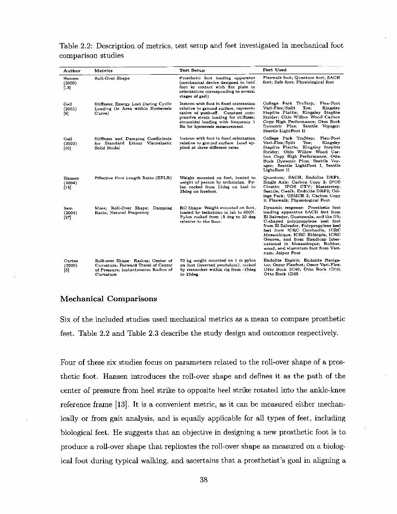
Table 2.2: Description of metrics, test setup and feet investigated in mechanical footcomparison studies
Author Metrics Test Setup Feet Used
Hansen Roll-Over Shape(2000)
[13]
Geil Stiffness; Energy Lost During Cyclic(2001) Loading (ie Area within Hysteresis
[9] Curve)
Geil Stiffness and Damping Coefficients(2002) for Standard Linear Viscoelastic[10] Solid Model
Hansen Effective Foot Length Ratio (EFLR)(2004)[15]
Sam Mass; Roll-Over Shape; Damping(2004) Ratio; Natural Frequency[27]
Curtze Roll-over Shape: Radius; Center of(2009) Curvature; Forward Travel of Center[5] of Pressure; Instantaneous Radius of
Curvature
Prosthetic foot loading apparatus(mechanical device designed to loadfoot in contact with flat plate inorientations corresponding to severalstages of gait)
Instron with foot in fixed orientationrelative to ground surface, represen-tative of push-off. Constant com-pressive strain loading for stiffness;sinusoidal loading with frequency 1Hz for hysteresis measurement.
Instron with foot in fixed orientationrelative to ground surface. Load ap-plied at three different rates.
Weight mounted on foot, loaded toweight of person by technician. Py-lon rocked from 15deg on heel to25deg on forefoot.
RO Shape: Weight mounted on foot,loaded by technician in lab to 600N.Pylon rocked from 15 deg to 30 degrelative to the floor.
70 kg weight mounted on 1 m pylonon foot (inverted pendulum), rockedby researcher within rig from -15degto 20deg
Mechanical Comparisons
Six of the included studies used mechanical metrics as a mean to compare prosthetic
feet. Table 2.2 and Table 2.3 describe the study design and outcomes respectively.
Four of these six studies focus on parameters related to the roll-over shape of a pros-
thetic foot. Hansen introduces the roll-over shape and defines it as the path of the
center of pressure from heel strike to opposite heel strike rotated into the ankle-knee
reference frame [13]. It is a convenient metric, as it can be measured either mechan-
ically or from gait analysis, and is equally applicable for all types of feet, including
biological feet. He suggests that an objective in designing a new prosthetic foot is to
produce a roll-over shape that replicates the roll-over shape as measured on a biolog-
ical foot during typical walking, and ascertains that a prosthetist's goal in aligning a
38
Flexwalk foot; Quantum foot; SACHfoot; Safe foot; Physiological foot
College Park TruStep; Flex-FootVari-Flex/Split Toe; KingsleySteplite Flattie; Kingsley StepliteStrider; Ohio Willow Wood CarbonCopy High Performance; Otto BockDynamic Plus; Seattle Voyager;Seattle LightFoot II
College Park TruStep; Flex-FootVari-Flex/Split Toe; KingsleySteplite Flattie; Kingsley StepliteStrider; Ohio Willow Wood Car-bon Copy High Performance; OttoBock Dynamic Plus; Seattle Voy-ager; Seattle LightFoot I, SeattleLightFoot II
Quantum; SACH; Endolite DRF1;Single Axis; Carbon Copy 2; IPOSCinetic; IPOS CTV; Masterstep;Seattle; Cwalk; Endolite DRF2; Col-lege Park; USMCE 2; Carbon Copy3; Flexwalk; Physiological Foot
Dynamic response: Prosthetic footloading apparatus SACH feet fromEl Salvador, Guatemala, and the US;C-shaped polypropylene keel footfrom El Salvador; Polypropylene keelfeet from ICRC Cambodia, ICRCMozambique, ICRC Ethiopia, ICRCGeneva, and from Handicap Inter-national in Mozambique; Rubber,wood, and alumnium foot from Viet-nam; Jaipur Foot
Endolite Espirit; Endolite Naviga-tor; Ossur Flexfoot; Ossur Vari-Flex;Otto Bock 1C40; Otto Bock 1D10;Otto Bock 1D35

Table 2.3: Outcomes of studies using mechanical metrics to compare prosthetic feet
Author Outcomes
Hansen Roll-over shape of a prosthetic is defined and proposed as indicator of performance. Flexwalk foot had roll-over(2000) shape nearly identical to physiological roll-over shape, which may explain its high performance in other published[13] studies. Quasistatic properties of prosthetic feet determine the roll-over shape of a foot; prosthetists likely align foot
such that roll-over shape of foot most closely matches orientation of physiological roll-over shape.
Geil Feet tested fell into four stiffness categories with little variation within each category. Flex-Foot lost least amount of(2001) energy during cyclic loading; College Park TruStep lost the most. However, Flex-Foot also required the least amount[9] of energy to load, so the percentage of energy lost was around average. All feet except Flex-Foot were tested with a
foam cosmesis.
Geil Prosthetic feet generally fit the standard linear viscoelastic solid model, with lowest R2
= 0.8982. The Flex-Foot and(2002) College Park feet were least accurately modeled, possibly due to compliant ankles. Flex-Foot showed non-linearity[10] in force versus deflection curve that was not captured. Most feet had similar damper coefficients, but Flex-Foot
was significantly lower, most likely due to absence of foam cosmesis. Stiffness coefficients varied more than dampingcoefficients. A more robust model is needed to capture behavior of all types of feet.
Hansen Effective foot length ratio (EFLR) is defined as the distance from the heel to the most anterior position of the center(2004) of pressure during a step over the total length of the foot. For physiological feet during typical walking, EFLR was[15] measured as 0.83. The EFLRs for the prosthetic feet studied here ranged from 0.63 to 0.81. A shorter EFLR may
lead to a 'drop-off' effect, in which the person using the prosthesis effectively falls onto his or her biological limb,resulting in asymmetrical step length and higher loads on the biological side.
Sam The mass of the prosthetic feet varied from 193.0 g to 854.6 g. The natural frequencies of all the feet were much(2004) higher than loading rate during normal walking, damping ratios were all low, such that dynamic properties were not[27] likely to affect the performance of the feet during walking. All of the feet had SACH-like roll-over shapes, except
for the Jaipur Foot, which was circular with a radius smaller than that of a physiological foot. None of the roll-overshapes extended into the toes, which could lead to 'drop-off' effect.
Curtze Radius of roll-over shape for the prosthetic feet varied around 312 mm. Putting the prosthetic feet in shoes reduced(2009) the radius of curvature. The horizontal position of the center of curvature varied greatly between prosthetic feet.[5] The forward progression of the center of pressure on the ground with respect to the shaft angle is an 'S' shaped
curve, and may be an important metric to include with roll-over shape measurements.
prosthetic foot is to orient the roll-over shape of the foot such that it best matches
the roll-over shape of a biological foot.
Hansen's second study in this category investigated the effect of a single attribute
of the roll-over shape, which he calls the effective foot length ratio (EFLR) [15]. It
is defined as the ratio of the distance from the heel of the foot to the anterior-most
point on the roll-over shape (the effective foot length) to the overall length of the foot.
As with the roll-over shape, Hansen proposes that the optimal EFLR that which is
closest to the physiological value, which he found to be 0.83. Hansen suggests that a
prosthetic foot with too short of an EFLR results in what he calls a "drop-off" effect.
In this case, the prosthetic foot is unable to support the weight of the person using
the prosthesis as the center of pressure progresses out towards the toe. As a result,
the person tends to fall onto his or her other limb, resulting in asymmetrical step
lengths and higher ground reaction forces.
Sam measured the roll-over shapes and dynamic properties of 11 different feet used
in developing countries, and found that the roll-over shapes of all but the Jaipur foot
39

resembled that of a SACH foot, which is mostly flat with a steep curve upward at
the toes [27]. The Jaipur foot had a circular roll-over shape, which is close to what is
seen from biological feet, but the radius was smaller than that of a biological roll-over
shape. All of the feet studied here exhibited a small EFLR.
Curtze also investigated roll-over shape of commercially available prosthetic feet, but
measured more individual parameters describing the shape: the radius, the horizontal
center of curvature, the forward travel of the center of pressure, and the instantaneous
radius of curvature [5]. While other studies have discussed radius and center of cur-
vature [23, 24], to the author's knowledge, this is the first study that has considered
the forward travel of center of pressure. This could be an important parameter, as
a foot could exhibit a physiological roll-over shape but have very different rates of
progression of the center of pressure along that path. Further work is required to
determine how this particular metric influences prosthetic foot performance.
In both of his studies, Geil measured static and dynamic properties of feet using
an Instron. The prosthetic feet are oriented in a position that mimics push-off and
lowered to a flat surface such that the toes come in contact with the ground first.
In his first study, Geil found the stiffness of the feet in this position by applying a
constant strain rate and measuring stress. He then considered energy recovery prop-
erties by applying a sinusoidal strain rate and measuring differences in work done in
loading and unloading the foot. He found that stiffnesses of the different prosthetic
feet on the market fell into one of four categories, with little variation within each
category. Energy recovery varied much more. The Flex-Foot had the least amount of
energy loss and was also the only foot tested without a foam cosmesis, which suggests
that the cosmesis is responsible for most of the energy dissipation during loaded, as
is expected [9].
In his 2002 study, Geil performed a very similar test, but modeled prosthetic feet
using a standard model for linear viscoelastic solids - a spring in parallel with a
40

spring and damper in series. Three different constant strain rates were applied to
prosthetic feet oriented relative to a flat plate in a position representative of push-off;
the measured stress in each of these cases was used to find the damping coefficient and
the stiffnesses in each of the springs in the viscoelastic model. Geil concluded that
most of the feet tested fit the viscoelastic model very well, but it failed to capture the
non-linearity of the Flex-Foot, which indicates a need for a more robust model. In the
force versus displacement plots Geil presents, there is minimal difference in behav-
ior for the different loading rates, which suggests to the author that a linear elastic
model might be more appropriate for the loading of prosthetic feet in this manner. It
appears that little benefit is gained by adding the complexity of a viscoelastic model
[10].
Subjective and Metabolic Comparisons
Studies that use subjective questionnaires or metabolic measurements to compare
prosthetic feet are discussed together because, unlike mechanical or gait analysis mea-
surements, both subjective and metabolic metrics can clearly show the superiority of
a prosthetic foot over another prosthetic foot. A prosthetic foot that allows a user to
expend less energy while walking is superior to a prosthetic foot that requires more
energy expenditure, and a prosthetic foot that people rank highly is superior to a
prosthetic foot that people rank poorly. Determining what mechanical and gait anal-
ysis parameters cause feet to be superior lacks a definitive answer. Thus subjective
and metabolic metrics both provide useful evaluation tools for existing prosthetic feet.
Of the included studies, three used subjective preferences to compare prosthetic feet
(Table 2.4), and five used metabolic parameters (Table 2.5). The outcomes of the
studies performing metabolic comparisons are presented in Table 2.6.
Each of the studies using subjective metrics used different methods to achieve the
results. Huang had subjects rank the comfort of each prosthetic foot on a scale from
0 - 7 during normal walking, walking on a slope, walking on grass, and fast walking.
41

Table 2.4: Descriptions and outcomes of studies using subjective comparisons ofprosthetic feet
Author Type of Questionnaire Feet Used Outcomes
Huang Comfortable ambulation score (0 = SACH foot; Single Axis Multiple Axis foot was most comfortable,(2001) impossible, 7 = excellent) for normal foot; Multiple Axis foot then Single Axis, then SACH. No signifi-
[18] walking, walking on a slope, walking cant difference was found in questionnaire
on grass, and fast walking. between vascular and traumatic groups.
Klodd Preference Ranking Five experimental prototype F3 and F4 both ranked significantly better(2010) Shape&Roll feet of varying than Fl. F3 was designed to most closely
[21] flexibility (roll-over shape replicate physiological roll-over shape, F4radius of curvature varied was slightly stiffer. F1 was most flexiblefrom 15% of leg length for foot.F1 to 55% of leg length forF5)
Gailey Self-Report Questionnaires (Pros- SACH foot; SAFE foot; None of the self-report or performance mea-(2012) thesis Evaluation Questionnaire- Talux foot; Proprio foot sures were able to detect differences between
[7] Mobility Scale, Locomotor Capabil- (microprocessor ankle) prosthetic feet, suggesting that either theseities Index - 5); Two performance- tests are inadequate at measuring these dif-based measures (Amputee Mobility ferences, possibly due to a "ceiling effect", orPredictor with a prosthesis and that K-levels are not adequate. Some of the6-minute walk test); Steps per tests were able to distinguish in pre-trainingday and hours of activity per day versus post-training and in peripheral vascu-measured with step activity monitor lar disease (PVD) versus non-PVD.
Table 2.5: Descriptions of studies using metabolic parameters to compare prostheticfeet
Author Metrics Method Feet Used
Energy Cost [m1O2/kg/min]; GaitEfficiency [m102/kg/m]; RelativeExercise Intensity (percentage ofage-predicted maximum heart rate)
Energy Rate [ml02/kg/min]
Net metabolic rate [W/kg]
Oxygen Cost [m102/kg/m]
Metabolic energy expenditure rate[W/kg].
Oxygen uptake and heart rate mea-surement during walking on tread-mill at five different speeds.
Oxygen uptake measurement dur-ing walking on treadmill at threedifferent speeds and three differentinclinations.
Oxygen consumption and C02 pro-duction measurement on treadmillat fixed speed and cadence.
Oxygen uptake measurement dur-ing walking on treadmill at self-selected walking speed.
Oxygen consumption and C02 pro-duction measurement on treadmillat fixed speed.
SACH foot; Flex-Foot; Re-FlexVertical Shock Pylon
SACH foot; Single Axis foot; Mul-tiple Axis foot
Rigid arcs with seven differentradii of curvature (0.02, 0.05,0.10,0.15, 0.225,0.30,0.40 m) at-tached to boots that limit ankle mo-tion for persons without amputa-tions.
Five experimental prototypeShape&Roll feet of varying flex-ibility (roll-over shape radius ofcurvature varied from 15% of leglength for F1 to 55% of leg lengthfor F5).
Five rigid arcs with radius of 0.40 mand lengths 0.203, 0.229, 0.254,0.279, and 0.305 m; Two otherswith length 0.254 m and radii 0.30and 0.60 m.
42
Hsu(2000)[17]
Huang(2001)[18]
Adamczyk(2006)[1]
Klodd(2010)[21]
Adamczyk(2013)[2]
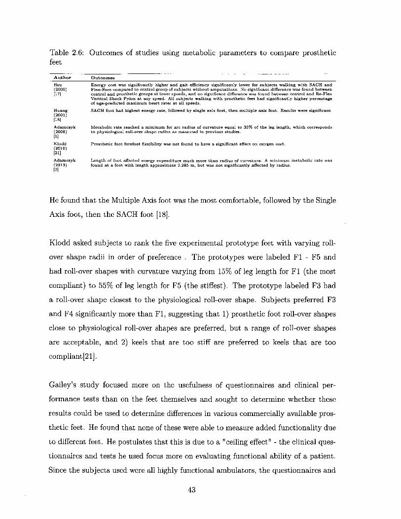
Table 2.6: Outcomes of studies using metabolic parameters to compare prostheticfeet
Author Outcomes
Hsu Energy cost was significantly higher and gait efficiency significantly lower for subjects walking with SACH and(2000) Flex-Foot compared to control group of subjects without amputations. No significant difference was found between[17] control and prosthetic groups at lower speeds, and no significant difference was found between control and Re-Flex
Vertical Shock Pylon at any speed. All subjects walking with prosthetic feet had significantly higher percentageof age-predicted maximum heart rates at all speeds.
Huang SACH foot had highest energy rate, followed by single axis foot, then multiple axis foot. Results were significant.(2001)[18]
Adamczyk Metabolic rate reached a minimum for arc radius of curvature equal to 30% of the leg length, which corresponds(2006) to physiological roll-over shape radius as measured in previous studies.[1]
Klodd Prosthetic foot forefoot flexibility was not found to have a significant effect on oxygen cost.(2010)[21]
Adamczyk Length of foot affected energy expenditure much more than radius of curvature. A minimum metabolic rate was(2013) found at a foot with length approximate 0.285 m, but was not significantly affected by radius.[2]
He found that the Multiple Axis foot was the most comfortable, followed by the Single
Axis foot, then the SACH foot [18].
Klodd asked subjects to rank the five experimental prototype feet with varying roll-
over shape radii in order of preference . The prototypes were labeled F1 - F5 and
had roll-over shapes with curvature varying from 15% of leg length for F1 (the most
compliant) to 55% of leg length for F5 (the stiffest). The prototype labeled F3 had
a roll-over shape closest to the physiological roll-over shape. Subjects preferred F3
and F4 significantly more than F1, suggesting that 1) prosthetic foot roll-over shapes
close to physiological roll-over shapes are preferred, but a range of roll-over shapes
are acceptable, and 2) keels that are too stiff are preferred to keels that are too
compliant[21].
Gailey's study focused more on the usefulness of questionnaires and clinical per-
formance tests than on the feet themselves and sought to determine whether these
results could be used to determine differences in various commercially available pros-
thetic feet. He found that none of these were able to measure added functionality due
to different feet. He postulates that this is due to a "ceiling effect" - the clinical ques-
tionnaires and tests he used focus more on evaluating functional ability of a patient.
Since the subjects used were all highly functional ambulators, the questionnaires and
43

tests were unable to measure small increases in performance. This suggests that these
clinical outcome measurements are poor tools for evaluating prosthetic foot perfor-
mance [7].
Most of the studies that considered metabolic parameters used the energy cost of
walking on a treadmill measured through oxygen consumption in milliliters of oxygen
per kilogram per minute. Only the two studies conducted by Adamczyk reported the
net metabolic rate of walking in watts per kilogram by measuring both oxygen intake
and carbon dioxide production and using an empirical formula to calculate power
output [1, 2].
Hsu found that persons walking with a SACH foot or a Flex-Foot expended more
energy in walking at fast speeds than persons without amputations [17]. Surprisingly
no difference was found at lower speeds. Subjects walking with the Re-Flex Vertical
Shock Pylon, did not expend significantly more energy than the subjects without
amputations during walking at any speed. This suggests that the Re-Flex Vertical
Shock Pylon is superior to the SACH foot and the Flex-Foot in terms of energy cost.
Nothing can be said about the relative merits of the SACH foot and the Flex-Foot,
as the two were not directly compared within the study.
Huang's results in metabolic parameters matched his results in subjective prefer-
ence - the multiple axis foot, which was rated the most comfortable, required the
least amount of energy expenditure, followed by the single axis foot, then the SACH
foot, which was rated the least comfortable [18]. This supports the idea that feet that
require less energy expenditure are superior to feet that require more.
Both Klodd and Adamczyk used experimental prototype feet to isolate and vary
specific features. Both essentially focused on roll-over shape, although went about
doing so in different ways. Klodd started with a Shape&Roll foot, a prosthetic foot
that was designed to mimic the ideal roll-over shape by bending through a series of
44

flexural hinges. By changing the number and spacing of the flexural hinges, both the
stiffness and the roll-over shape of the prototype foot was altered, resulting in five
different feet labeled F1 - F5, as previously discussed [21]. Adamczyk's prototypes
were simply solid arcs of different radii that were attached to the bottom of AirCast
Pneumatic Walking Boots, which restricted biological ankle motion of the wearer.
The result was an imposed roll-over shape, or rocker radius, with all other variables,
such as energy storage, stiffness, etc., eliminated [1]. A follow-up study was performed
that also varied the length of the rigid arcs [2].
While Klodd was unable to find a significant difference in energy rate between the
prototype feet, Adamczyk found that the metabolic cost of walking reached a mini-
mum for arcs of radius 30% of the leg length [1]. However, his follow up work found
that the arc length had a much greater effect on the energetic cost of walking than
the radius [2]. The difference in results between Klodd and Adamczyk could be ex-
plained by a) alterations in stiffness and roll-over shape unintentionally altering other
features of prototypes in Klodd's study, b) arc length remaining unchanged between
prototypes in Klodd, c) use of persons with amputations in Klodd, as opposed to
persons without amputations wearing boots to restrict ankle motion in Adamczyk.
Gait Analysis Comparisons
In this discussion, 'gait analysis' pertains to any study which uses any combination
of force place, motion capturing systems, and, in the case of Fey [6], EMG elec-
trodes. The studies included were not limited to those using subjects with amputa-
tions - Hansen and Adamczyk utilized subjects without amputations with a pseudo-
prosthesis boot which restricts ankle motion and to the bottom of which prosthetic
feet can be attached. The included studies and their more important outcomes are
provided in Table 2.7.
The Adamczyk studies, the Hansen studies, and the Klodd study all focus on the ef-
fects of changing different roll-over shape characteristics of the feet. The 2000 Hansen
45
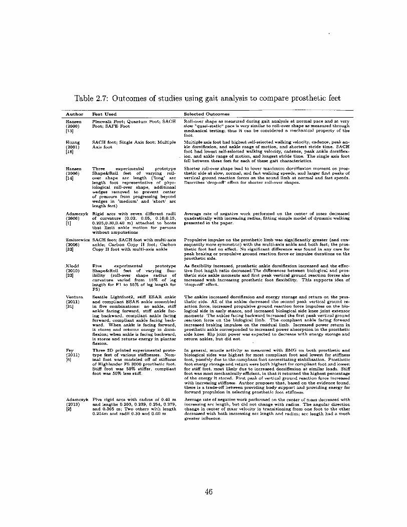
Table 2.7: Outcomes of studies using gait analysis to compare prosthetic feet
Author Feet Used Selected Outcomes
Hansen(2000)[13]
Huang(2001)[18]
Flexwalk Foot; Quantum Foot; SACHFoot; SAFE Foot
SACH foot; Single Axis foot; MultipleAxis foot
Hansen Three experimental prototype(2006) Shape&Roll feet of varying roll-[14] over shape arc length ('long' arc
length foot representative of phys-iological roll-over shape, additionalwedges removed to prevent centerof pressure from progressing beyondwedges in 'medium' and 'short' arclength feet)
Adamczyk Rigid arcs with seven different radii(2006) of curvature (0.02, 0.05, 0.10,0.15,
[1] 0.225,0.30,0.40 m) attached to bootsthat limit ankle motion for personswithout amputations
Zmitrewicz SACH foot; SACH foot with multi-axis(2006) ankle; Carbon Copy II foot; Carbon[32] Copy II foot with multi-axis ankle
.Klodd Five experimental prototype(2010) Shape&Roll feet of varying flex-[22] ibility (roll-over shape radius of
curvature varied from 15% of leglength for F1 to 55% of leg length forF5)
Ventura Seattle Lightfoot2, stiff ESAR ankle(2011) and compliant ESAR ankle assembled[31] in five combinations: no ankle, stiff
ankle facing forward, stiff ankle fac-ing backward, compliant ankle facingforward, compliant ankle facing back-ward. When ankle is facing forward,it stores and returns energy in dorsi-flexion; when ankle is facing backward,it stores and returns energy in plantarflexion.
Fey Three 3D printed experimental proto-(2011) type feet of various stiffnesses. Nom-[6] inal foot was modeled off of stiffness
of Highlander FS 3000 prosthetic foot.Stiff foot was 50% stiffer, compliantfoot was 50% less stiff.
Adamczyk Five rigid arcs with radius of 0.40 m(2013) and lengths 0.203, 0.229, 0.254, 0.279,[2] and 0.305 m; Two others with length
0.254m and radii 0.30 and 0.60 m
Roll-over shape as measured during gait analysis at normal pace and at veryslow "quasi-static" pace is very similar to roll-over shape as measured throughmechanical testing; thus it can be considered a mechanical property of thefoot.
Multiple axis foot had highest self-selected walking velocity, cadence, peak an-kle dorsiflexion, and ankle range of motion, and shortest stride time. SACHfoot had lowest self-selected walking velocity, cadence, peak ankle dorsiflex-ion, and ankle range of motion, and longest stride time. The single axis footfell between these feet for each of these gait characteristics.
Shorter roll-over shape lead to lower maximum dorsiflexion moment on pros-thetic side at slow, normal, and fast walking speeds, and larger first peaks ofvertical ground reaction forces on the sound limb at normal and fast speeds.Describes 'drop-off' effect for shorter roll-over shapes.
Average rate of negative work performed on the center of mass decreasedquadratically with increasing radius, fitting simple model of dynamic walkingpresented in the paper.
Propulsive impulse on the prosthetic limb was significantly greater (and con-sequently more symmetric) with the multi-axis ankle and both feet; the pros-thetic foot had no effect. No significant difference was found in any case forpeak braking or propulsive ground reaction force or impulse durations on theprosthetic side.
As flexibility increased, prosthetic ankle dorsiflexion increased and the effec-tive foot length ratio decreased.The differences between biological and pros-thetic side ankle moments and first peak vertical ground reaction forces alsoincreased with increasing prosthetic foot flexibility. This supports idea of'drop-off' effect.
The ankles increased dorsiflexion and energy storage and return on the pros-thetic side. All of the ankles decreased the second peak vertical ground re-action force, increased propulsive ground reaction force impulses on the bio-logical side in early stance, and increased biological side knee joint extensormoments. The ankles facing backward increased the first peak vertical groundreaction force on the biological limb. The compliant ankle facing forwardincreased braking impulses on the residual limb. Increased power return inprosthetic ankle corresponded to increased power absorption in the prostheticside knee. Hip joint power was expected to decrease with energy storage andreturn ankles, but did not.
In general, muscle activity as measured with EMG on both prosthetic andbiological sides was highest for most compliant foot and lowest for stiffnessfoot, possibly due to the compliant foot necessitating stabilization. Prostheticfoot energy storage and return were both highest for compliant foot and lowestfor stiff foot, most likely due to increased dorsiflexion at similar loads. Stifffoot was most mechanically efficient, in that it returned the highest percentageof the energy it stored. First peak of vertical ground reaction force increasedwith increasing stiffness. Author proposes that, based on the evidence found,there is a trade-off between providing body support and providing energy forforward propulsion in selecting prosthetic foot stiffness.
Average rate of negative work performed on the center of mass decreased withincreasing arc length, but did not change with radius. The angular directionchange in center of mass velocity in transitioning from one foot to the otherdecreased with both increasing arc length and radius; arc length had a muchgreater influence.
46

study measured the roll-over shapes of prosthetic feet for persons without amputa-
tions in two conditions: walking normally, and walking very slowly in a 'quasi-static'
state. The purpose was merely to compare the roll-over shapes obtained from gait
analysis to those measured mechanically, as previously discussed. He found that there
was very little difference between the different methods, and thus roll-over shapes are
mechanical properties inherent to the design of a prosthetic foot [13]. The Adamczyk
studies are primarily concerned with metabolic rates, as discussed above, but also use
force plates and other sensors to measure the mechanical work done on the center of
mass in redirecting it during step-to-step transition [1, 2]. As expected, this is corre-
lated with metabolic rates. The Klodd study compares the same prototype prosthetic
feet with changing roll-over shape radius that were investigated in a separate study
during the same year that focused on the metabolic rates and subjective preferences of
persons using those feet. She found that feet with smaller roll-over shape radii result
in increased ankle dorsiflexion, decreased effective foot length ratio, and decreased
symmetry in ankle moments and first peak vertical ground reaction forces [22]. For
the 2006 Hansen study, the same prototype foot was modified in a different way such
that the roll-over shape arc length was shortened, but the radius remained the same.
He found that shorter roll-over shape arc lengths lead to increased vertical ground
reaction forces on the biological limb, in agreement with Klodd. Hansen and Klodd
have coined the term 'drop-off' effect to describe this.
Both Zmitrewicz and Huang measured some benefit from multi-axis ankles. Huang
found that a multi axis foot had highest self-selected walking velocity and cadence
compared to a single axis foot and a SACH foot [18]. Zmitrewicz found that the pros-
thetic side propulsive impulse was larger and consequently more symmetric between
legs when a multi-axis ankle was added to both a SACH foot and a Carbon Copy II
foot; the prosthetic feet had no measurable effect [32].
Ventura and Fey investigated ankle/foot compliance and energy storage and return.
Both provided data for many different gait parameters. The general takeaway from
47

both papers is essentially that muscles in both legs are more active when a person is
using a more compliant prosthetic foot - the increased muscle activity is required for
stability, and possibly negates the benefits of energy storage and return feet/ankles
[6, 31];
2.4 Discussion
Stiffness and energy loss, as considered by Geil [9], are excellent examples of the con-
voluted nature of how mechanical properties affect function of prosthetic feet. The
amount of energy dissipated during dynamic loading was presented in four different
ways: work done on the foot in loading, work done on the foot in unloading, the
difference between these two values (ie energy loss), and the percentage of the work
done in loading the foot that was dissipated. The only context Geil offers for inter-
preting these data is that energy recovery is intended to facilitate limb advancement
in prosthetic gait. By thinking through a step on a prosthetic foot from an engineer-
ing perspective, it is possible to go deeper than this analysis.
If it is assumed that ground reaction forces are dependent only on a person's mass,
then each foot a single person is wearing will see the same load immediately prior to
push-off. The amount this foot deflects, or the amount of dorsiflexion it provides, can
be determined using the stiffness of the foot. Since the feet in the study exhibited
constant stiffnesses during loading, then the differences in energy done on each foot
are dependent only on the stiffness of the feet - when a set force is applied to a stiffer
foot, it will deflect less and thus less work will be done on the foot than when the
same force is applied to the less stiff foot. Of this total strain energy stored in the
foot, some of it is dissipated and the rest is available to assist in providing push-off.
By this logic, the amount of work done by the foot on the Instron during unloading
might be the most important of the parameters presented, as it is the amount of
energy a person wearing a prosthetic foot could transfer for propulsion. However, at
least one study has shown that with a prototype prosthetic foot, increased positive
48

power output at the prosthetic ankle resulted in increased power absorption in the
knee of the same leg, so a prosthetic foot being able to store and return energy does
not in and of itself result in more efficient gait [6].
Additionally, while the initial assumption made in the previous paragraph, that the
ground reaction forces are dependent only on a person's mass, is necessary to think
through the meaning of each of these parameters, it is inaccurate. A person's gait is
influenced by the behavior of the prosthetic foot he or she is wearing, as evidenced by
all of the gait analysis studies herein; simultaneously, the behavior of the prosthetic
foot is affected by the user's gait. Thus it is very difficult to isolate a single mechan-
ical property and correlate it to a single measurable gait parameter.
From the studies using subjective comparisons, the most useful conclusion is that
clinical tests are inadequate for evaluating prosthetic feet [7]. The metabolic studies
support mimicking a physiological roll-over shape and foot arc length, which agrees
with Hansen's hypotheses [13, 15, 14].
An issue inhibiting progress in the field of prosthetics is the lack of an agreed upon
set of metrics. Inconsistency in mechanical, metabolic, and gait analysis parameters
and how they are measured makes it very difficult to draw conclusions across mul-
tiple studies. One metric that stands out as a consistent choice is roll-over shape,
due in large part to sheer quantity of papers published on the topic from Hansen and
the Prosthetics Research Laboratory at Northwestern University. Of the 17 studies
included in this review, nine studies (six of which included Hansen as an author) dis-
cussed roll-over shape as a metric. Roll-over shape is particularly useful as it can be
measured either mechanically or through gait analysis, is applicable for any type of
foot [13], and is shown to have an effect on energy cost [1, 2]. The body of work done
by Hansen, Klodd, and Adamczyk all seem to be directed toward a similar conclusion
- that having a physiological roll-over shape is important to achieve optimal gait, and
that the arc length of that roll-over shape has a bigger effect on gait than the radius.
49
One benefit of Adamczyk's work is that he provides analytical models of walking,
which he uses to predict why and how the different feet will affect energy expendi-
ture. By using this model, he is able to identify that it is specifically the arc length of
the roll-over shape, rather than the radius, which effects metabolic rates. The author
believes that this analysis is what is missing from the majority of papers on passive
prosthetic feet. Too often an abundance of data is presented without an adequate
explanation of why the data is what it is based on physics rather than based on previ-
ous studies of prosthetic feet. This is particularly true with gait analysis, as once it is
performed, there is a profusion of parameters that can be compared: vertical ground
reaction forces, propulsive and braking ground reaction forces, moments at each joint,
peak angles at each joint, range of motion at each joint, power at each joint, etc. Each
of these has different markers that can be compared, e.g. the vertical ground reac-
tion force curve has two characteristic peaks, one during early stance and one during
late stance. The value of the ground reaction force at either of these peaks can be
compared. Furthermore, there are many bases for comparison - biological limb versus
prosthetic limb, different feet on the same limb, persons with amputations versus nor-
mative gait data, and persons with amputations due to trauma versus amputations
due to vascular disease. The data quickly becomes overwhelming; too many authors
present all of this data and leave the onus on the reader to determine what it all means,
or they provide a theoretical explanation for the data without sufficiently validating
it. In contrast, Adamczyk used physics to predict what will happen, tested his hy-
pothesis without introducing extraneous variables, and found the results he expected.
While a few papers do span multiple categories of comparison above, it is the au-
thor's opinion that more studies should be done that include metrics from each of
these categories to better understand particularly the effect of mechanical properties
on gait analysis parameters, and gait analysis parameters on energy expenditure, and
all of these factors on user satisfaction.
50

2.5 Conclusion
In order to gain insight into what makes one prosthetic foot/ankle component better
or worse than another one, methods of comparing prosthetic feet both in industry and
in academia are reviewed. Tests used in industry include the mechanical tests devel-
oped by the AOPA Prosthetic Foot Project Task Force in conjunction with many of
the major manufacturers of prosthetic feet and ISO 22675. The AOPA tests serve to
characterize mechanical differences between prosthetic feet to facilitate the Medicare
reimbursement process. ISO 22675 tests the durability of prosthetic foot components
and ensures user safety. It is important to know how a new foot will perform in these
tests as they will provide indication of how the foot fits in to the existing prosthetics
market, but these tests are based on existing products rather than scientific knowl-
edge and make it clear that they are not intended to be used as recommendations for
what a prosthetic foot should be able to do.
Studies comparing prosthetic feet in academia have largely failed to produce any
consistent results. The publications discussed herein fall into one of four categories:
mechanical comparisons, metabolic comparisons, subjective comparisons, and gait
analysis comparisons. Mechanical comparisons offer the best insight for designing
a new prosthetic foot, as mechanical properties can be optimized using engineering
principles. However, very little is understood about how these mechanical properties
affect the performance of a prosthetic foot. On the other end of the spectrum are
metabolic and subjective comparisons. These are useful tools for evaluating pros-
thetic feet as desirable outcomes are clear, but cannot be applied until a prosthetic
foot is built and ready for use, so these are ineffective during early stage design. Gait
analysis falls in between these two groupings. There is a need for more studies to
bridge the gap between these categories in order to make links between desirable
evaluation outcomes and mechanical properties.
From the literature reviewed here, two properties emerge as relatively important: the
51

roll-over shape of a prosthetic foot and the energy storage and return capacity. Based
on the above discussion, a physiological roll-over shape and high capacity for energy
storage and return are likely necessary, but not sufficient, in achieving a high level of
performance from a prosthetic foot. No passive prosthetic foot has consistently and
conclusively been shown to have higher subjective preference or lower metabolic rates
of walking than other prosthetic feet. The goal of passive prosthetic foot research
should be to achieve this. This literature review suggests that the best way to do this
is by focusing on roll-over shape and energy storage and return for initial design, then
using subjective feedback and biomechanics gait data to further optimize for other
parameters that emerge.
52

Bibliography
[1] P. G. Adamczyk, S. H. Collins, and A. D. Kuo. The advantages of a rolling foot
in human walking. The Journal of Experimental Biology, 209(Pt 20):3953-63,
Oct. 2006.
[2] P. G. Adamczyk and A. D. Kuo. Mechanical and energetic consequences of
rolling foot shape in human walking. The Journal of experimental biology, 216(Pt
14):2722-31, July 2013.
[3] American Academy of Orthotists and Prosthetists. Official findings of the state-
of-the-science conference on prosthetic foot/ankle mechanisms. Journal of Pros-
thetics and Orthotics, 17(4S):1-52, 2005.
[4] American Orthotic and Prosthetic Association. Aopa prosthetic foot project re-
port. Technical report, American Orthotic and Prosthetic Association, Septem-
ber 2010.
[5] C. Curtze, A. L. Hof, H. G. van Keeken, J. P. K. Halbertsma, K. Postema,
and B. Otten. Comparative roll-over analysis of prosthetic feet. Journal of
Biomechanics, 42:1746-1753, 2009.
[6] N. P. Fey, G. K. Klute, and R. R. Neptune. The influence of energy storage
and return foot stiffness on walking mechanics and muscle activity in below-knee
amputees. Clinical Biomechanics, 26:1025-1032, 2011.
[7] R. S. Gailey, I. Gaunaurd, V. Agrawal, M. S. Bioe, C. 0. Toole, and R. Tolchin.
Application of self-report and performance-based outcome measures to deter-
53

mine functional differences between four categories of prosthetic feet. Journal of
Rehabilitation Research & Development, 49(4):597-612, 2012.
[8] R. S. Gailey, M. A. Wenger, M. Raya, N. Kirk, K. Erbs, P. Spyropoulos, and
M. S. Nash. Energy expenditure of trans-tibial amputees during ambulation
at self-selected pace. Prosthetics and orthotics international, 18(2):84-91, Aug.
1994.
[9] M. D. Geil. Energy loss and stiffness properties of dynamic elastic response
prosthetic feet. Journal of Prosthetics and Orthotics, 13(3):70-73, 2001.
[10] M. D. Geil. An iterative method for viscoelastic modeling of prosthetic feet.
Journal of Biomechanics, 35:1405-1410, 2002.
[11] A. Gitter, J. M. Czerniecki, and D. M. DeGroot. Biomechanical analysis of the
influence of prosthetic feet on below-knee amputee walking. American Journal
of Physical Medicine & Rehabilitation, 70(3):142-148, 1991.
[12] B. Hafner, J. Sanders, J. Czerniecki, and J. Fergason. Transtibial energy-storage-
and-return prosthetic devices: A review of energy concepts and a proposed
nomenclature. Journal of Rehabilitation Research and Development, 39(1):1-11,
January/February 2002.
[13] A. H. Hansen, D. S. Childress, and E. H. Knox. Prosthetic foot rollaAnover
shapes with implications for alignment of trans&ARtibial prostheses. Prosthetics
and Orthotics International, 24(3):205-215, Jan. 2000.
[14] A. H. Hansen, M. R. Meier, P. H. Sessoms, and D. S. Childress. The effects of
prosthetic foot roll-over shape arc length on the gait of trans-tibial prosthesis
users. Prosthetics and orthotics international, 30(3):286-99, Dec. 2006.
[15] A. H. Hansen, M. Sam, and D. S. Childress. The Effective Foot Length Ratio:
A Potential Tool for Characterization and Evaluation of Prosthetic Feet. JPO
Journal of Prosthetics and Orthotics, 16(2):41-45, Apr. 2004.
54

[16] C. Hofstad, H. van der Linde, J. van Limbeek, and K. Postema. Prescription of
prosthetic ankle-foot mechanisms after lower limb amputation ( Review ). The
Cochrane Library, 1, 2009.
[17] M.-J. Hsu, D. H. Nielsen, J. Yack, D. G. Shurr, and S.-J. Lin. Physiologi-
cal comparisons of physically active persons with transtibial amputation using
static and dynamic prostheses versus persons with nonpathological gait during
multiple-speed walking. Journal of Prosthetics and Orthotics, 12(2):60-67, 2000.
[18] K.-F. Huang, Y.-L. Chou, F.-C. Su, and P.-H. Chou. Kinematic properties and
energy cost of below-knee amputees. Biomedical Engineering, 13(2):99-107, 2001.
[19] International Organization for Standardization. ISO 22675: Prosthetics - Testing
of ankle-foot devices and foot units - Requirements and test methods, 2006.
[20] J. S. Jensen and H. B. Treichl. Mechanical testing of prosthetic feet utilized in
low-income countries according to ISO-10328 standard. Prosthetics and Orthotics
International, 31(2):177-206, June 2007.
[21] E. Klodd, A. Hansen, S. Fatone, and M. Edwards. Effects of prosthetic foot
forefoot flexibility on oxygen cost and subjective preference rankings of unilateral
transtibial prosthesis users. Journal of Rehabilitation Research & Development,
47(6):543-552, 2010.
[22] E. Klodd, A. Hansen, S. Fatone, B. P. 0. Hons, and M. Edwards. Effects of
prosthetic foot forefoot flexibility on gait of unilateral transtibial prosthesis users.
Journal of Rehabilitation Research & Development, 47(9):899-910, 2010.
[23] E. H. Knox. The role of prosthetic feet in walking. PhD thesis, Northwestern
University, 1996.
[24] T. McGeer. Passive Dynamic Walking. The International Journal of Robotics
Research, 9(2):62-82, Apr. 1990.
55

[25] K. Postema, H. J. Hermens, J. De Vries, H. F. J. M. Koopman, and W. H.
Eisma. Energy storage and release of prosthetic feet Part 1: biomechanical
analysis related to user benefits. Prosthetics and Orthotics International, 21:17-
27, 1997.
[26] K. Postema, H. J. Hermens, J. De Vries, H. F. J. M. Koopman, and W. H.
Eisma. Energy storage and release of prosthetic feet Part 2: subjective ratings of
2 energy storing and 2 conventional feet, user choice of foot and deciding factor.
Prosthetics and Orthotics International, 21:28-34, 1997.
[27] M. Sam, A. H. Hansen, and D. S. Childress. Characterisation of prosthetic
feet used in low-ARincome countries. Prosthetics and Orthotics International,
28(2):132-140, Jan. 2004.
[28] R. D. Snyder, C. M. Powers, C. Fontaine, and J. Perry. The effect of five pros-
thetic feet on the gait and loading of the sound limb in dysvascular below-knee
amputees. Journal of Rehabilitation Research & Development, 32(4):309-315,
1995.
[29] L. Torburn, J. Perry, E. Ayyappa, and S. Shanfield. Below-knee amputee gait
with dynamic elastic response prosthetic feet : a pilot study . Journal of Reha-
bilitation Research & Development, 27(4):369-384, 1990.
[30] H. van der Linde, J. Cheriel, and C. H. Alexander. A systematic literature
review of the effect of different prosthetic components on human functioning
with a lower-limb prosthesis. Journal of Rehabilitation Research & Development,
41(4):555-570, 2004.
[31] J. D. Ventura, G. K. Klute, and R. R. Neptune. The effects of prosthetic an-
kle dorsiflexion and energy return on below-knee amputee leg loading. Clinical
Biomechanics, 26(3):298-303, Mar. 2011.
[32] R. J. Zmitrewicz, R. R. Neptune, J. G. Walden, W. E. Rogers, and G. W. Bosker.
The effect of foot and ankle prosthetic components on braking and propulsive
56

impulses during transtibial amputee gait. Archives of physical medicine and
rehabilitation, 87(10):1334-9, Oct. 2006.
57

58

Chapter 3
Theoretical Considerations for a
Mechanically Constrained Cantilever
Beam - Type Foot
3.1 Introduction
As explained in Section 2.1, there is no consensus as to how mechanical properties
affect performance of prosthetic feet. Establishing a better knowledge base regarding
how prosthetic foot features, such as stiffness, range of motion, and energy storage and
return, affect function would aide prosthesis designers in optimizing the performance
of foot/ankle systems. Based on the information that is available in the literature, as
discussed in Chapter 2, two mechanical features emerge as useful tools in early-stage
prosthetic foot/ankle design: energy storage and return, and the roll-over shape. A
brief summary of literature leading to that conclusion is below.
Energy Storage and Return
Persons with lower limb amputations using passive prostheses expend more energy
to walk than persons without amputations [12]. Energy expenditure increases for
59

persons with higher levels of amputations [44] and shorter residual limb lengths [13].
It has been shown that walking with a powered prosthetic foot/ankle can decrease
the metabolic cost of walking relative to using a passive prosthesis [4, 8]. There are
two major differences between powered and passive prosthetic feet/ankles - powered
prostheses can use sensors and controllers to alter function during different stages of
gait, and powered prostheses can supply a net positive work. In this work, the strict
cost and durability constraints preclude the use of batteries, sensors, controllers or
actuators. The best a passive prosthesis can do to mimic the performance of a pow-
ered prosthetic foot/ankle is to store and return as much energy to the prosthesis
user as possible.
It should be noted that while a few studies have shown that energy storage and
return (ESAR) prosthetic feet reduce the metabolic cost of walking compared to
the SACH foot [33, 7, 22], numerous studies have not found a significant difference
[40, 5, 29, 28, 34, 41, 21]. At least one study found that while a foot with increased
ESAR did increase positive work at the ankle, this corresponded to increased nega-
tive work, or power absorption, at the knee [10]. The metabolic benefit of powered
prostheses together with the inconsistent results for passive prostheses suggest that
maximizing energy storage and return is necessary but not sufficient. This work will
focus on the magnitude of energy stored and available for return in a prosthetic foot
during late stance phase while recognizing that further work needs to be done to
understand how to release this energy advantageously.
Roll-over Shape
While literature comparing prosthetic feet has not been able to conclusively deter-
mine the benefits of different types of prosthetic feet, a handful of studies suggest
that the Flex-Foot, when compared to the SACH foot and a few other commercially
available prosthetic feet, provides some measurable benefits, such as allowing users
to walk faster [33, 39], take longer steps [35, 39], expend less energy [33, 21, 31],
60

and walk more efficiently (decreased energy expenditure per step) [22, 21, 31]. The
Flex-Foot was also perceived as easier to walk with than the SACH foot [30], and
preferred over the SAFE foot for stability and mobility [42]. One study showed that
subjects using a Flex-Foot exhibited a higher first peak in vertical ground reaction
force on the prosthetic limb as opposed to the physiological limb, while the opposite
was true for all other feet in the study [35]. Unsurprisingly, the Flex-Foot was also
shown to provide more ankle dorsiflexion than the SACH foot [35, 39, 40, 28, 38].
Many studies did not find any significant difference between the Flex-Foot and other
prosthetic feet when measuring these same parameters. However, since the Flex-Foot
stands out more than any other foot, it is considered to be a high performance passive
prosthetic foot. For a review of all these studies and more, see Hofstad [20].
A proposed explanation for the subject preference and other benefits of the Flex-
Foot is that the roll-over shape, as defined in Section 1.1 of the Flex-Foot is nearly
identical to that of a physiological foot [16].
The roll-over shape is a useful tool for designing a prosthetic foot because it has been
shown to be invariant to walking speed [17], carrying weight [15], and heel height
[14]. It is applicable for any type of foot-ankle complex, including passive and active
prostheses and biological limbs, so it provides a basis of comparison across all feet.
Several studies have measured the roll-over shapes of a wide range of commercially
available prosthetic feet [16, 19, 9].
One study investigated the roll-over shapes of 11 different types of prosthetic feet
used in the developing world [37]. It was found that nearly all of the feet exhibited a
SACH-like roll-over shape, which is flat in the midfoot and turns upward very quickly
in the toe region, where the solid keel ends and the foot can no longer support the
body weight of the person using it. The one exception to this was the Jaipur foot,
which had a circular roll-over shape with a much smaller radius than a physiological
61

roll-over shape. This is likely to accommodate the increased dorsiflexion required for
squatting.
Intuitively, if a prosthetic foot mechanically replicates a biological roll-over shape, and
if a person using that foot walks in such a way that the center of pressure progresses
from heel to toe with ground reaction force magnitudes similar to those measured
during typical gait, then the kinematic and kinetic outputs of the foot/ankle will pro-
duce typical reaction torques and allow motion replicating expected gait patterns at
each of the proximal joints in the leg, which will make typical gait possible. Thus, as
suggested by Hansen [16], an objective of prosthetic foot design should be to mimic
the physiological roll-over shape.
Experimental Prosthetic Feet/Ankles to Isolate Specific Features
In response to the various studies previously mentioned that were unable to determine
how form affects function for existing commercial prosthetic feet, in the last decade
researchers began to conduct studies using experimental prototype feet. This enabled
them to isolate and modify a single feature at a time and measure the effect of only
that change on the performance of the prosthetic foot.
Several of these studies revolved around variations of the Shape&Roll foot, a pros-
thetic foot intended for use in developing countries and designed to replicate biological
roll-over shapes [36]. Hansen varied the arc length of the roll-over shape and found
that shorter arc lengths could not support the subject's body weight as the center of
pressure progressed toward the toe, causing the subject to fall onto his physiological
limb, as observed by a higher initial peak in the vertical ground reaction force on the
physiological limb [18]. Additionally, step lengths were more symmetric between the
physiological and prosthetic limbs for prosthetic feet with longer arc lengths due to
the same effect. Klodd investigated the effect of forefoot flexibility, consequently also
altering roll-over shape radius, and found that the most flexible prototypes resulted
62
in greater dorsiflexion, asymmetrical ground reaction forces, and shorter effective foot
length ratios, while the more stiff feet resulted in asymmetrical ankle moments [26].
She also found that the most flexible foot was ranked significantly worse than the feet
with flexibility allowing roll-over shapes closer to a physiological roll-over shape. No
difference was measured in oxygen cost during walking with the different prototype
feet [25].
Adamczyk also investigated roll-over shape or rocker radius, but did so by attaching
rigid arc shapes of various curvatures to the bottom of boots that constrained bio-
logical ankle motion. He found that the metabolic rate was optimal (lowest) - albeit,
still 45% higher than metabolic rates for typical walking - for arcs with a radius of
30% of the leg length, which corresponds to the best fit for physiological roll-over
shapes [1, 32]. However, further work suggested that this metabolic benefit is more
dependent on the length of the rigid arc rather than the curvature [2].
Fey created prototype prosthetic feet with keels of varying stiffnesses using a se-
lective laser sintering additive manufacturing technique and observed that feet with
more flexible keels increase range of motion and energy storage and return, but also
require greater muscle activity to provide stability, which diminishes the benefit in
total work [10]. Ventura started with a commercially available Seattle Lightfoot2
(Seattle Systems Inc., Poulsbo, WA, USA), and added ankle units that increased
dorsiflexion and energy storage and return. This study similarly showed that the
increase in energy storage and return in the ankle joint was counteracted by a simul-
taneous increase in knee power absorption [43].
One flaw of several of these studies is that, excluding Adamczyk, the starting point
for the prototypes is a particular geometry of a prosthetic foot that already has inher-
ent characteristic behavior. Thus while the authors claim to be investigating general
prosthetic forefoot flexibility, the results have limited meaning to different types of
prosthetic feet. This is evidenced by the fact that Fey, Ventura and Klodd all alter the
63

stiffness of their respective prototypes, but Fey does so by increasing keel thickness,
Ventura by adding a compliant ankle, and Klodd essentially by altering mechanical
constraints that prevent bending beyond a certain point. Each of these changes have
different implications for the mechanics of how the prosthetic foot behaves, which in
turn affects biomechanical gait parameters of persons using the feet. By simplifying a
prosthetic foot to physical models of its key components and investigating the effect
of a single mechanical property from a physical perspective, fundamental insight can
be gained and implications can be extrapolated to a much broader range of prosthetic
feet.
Finite element (FE) analysis provides a means to evaluate a prosthetic foot without
requiring that it be built, which requires time and money, and without introducing
variability that arises from human gait. FE methods have been used by others to
compare a new model foot to commercially available feet [11], to optimize the design
of a prosthetic foot to minimize a cost function, such as external work required at the
knee joint [24], and to supplement gait analysis by measuring mechanical properties
such as stress and strain of a prosthetic foot [6]. FE requires very little time invest-
ment in a particular design and thus enables quick iterations in early design. The
information learned is objective and, applied correctly, can provide valuable insight
into the effects of different properties on prosthetic feet.
In this work, we use beam bending theory and FE analysis to investigate a sim-
ple model of a prosthetic foot as a cantilever beam with and without a mechanical
constraint. We vary a single property of the beam, the bending stiffness, to determine
its affect on two metrics that are established to be important predictors of prosthetic
foot performance - energy storage and return and roll-over shape. Implications of
these results for any solid ankle, flexible keel prosthetic foot are discussed.
64

3.2 Unconstrained Cantilever Beam Model
In gait analysis, the ground reaction force, location of the center of pressure, and
the upward motion of the toe with respect to the axis defined by the ankle and knee
joints are all measured. These can be equated to the force, length, and deflection of
a cantilever beam, as depicted in Figure 3-1.
0.415 Seconds After Heel Contact
CoPPath
-- GRF
-0.2 -0.1 0 0.1 0.2
X Position Relative to Anide Frame [m]
0.415 Seconds After Heel Contact
0.2
V
Si
0~
0.3
0.11
0
-0.2 -0.1 0 0.1 0.2
X Position Relative to Anlde Frame [m]
Figure 3-1:beam model
Data measured during gaitof a prosthetic foot (right)
analysis (left) translated into a cantilever
Given the force and location of the center of pressure, the stiffness of a cantilever
beam can be found such that it deflects the desired amount, using the equation
(3.1)-M = EIEy 2
where M is the internal bending moment, x is the distance along the beam, y is the
deflection of the beam, E is the elastic modulus, and I is the area moment of inertia.
The quantity EI is also referred to as the bending stiffness of the beam. In the simple
case of a cantilever beam with a point load, the equation for the deflection at the
65
0.2
0.1
0
cc
F0.3
-0.1 -
-0.2 -
-0.1-
-0.2-

point where the load is applied is
FL3 (3.2)3EI
where 3 is the deflection at that point, F is the load applied perpendicular to the
beam, and L is the distance from the supported end of the beam to the application
point of the load.
The strain energy stored in a cantilever beam in bending is given by
U = J Fd6 (3.3)
where U is the strain energy stored and F and 6 are as previously defined.
This is a very simple calculation given one static load. What makes this difficult
for prosthetic feet is that each of these three quantities changes with time over the
course of a step.
The lab reference frame coordinates of every joint and the center of pressure be-
tween the foot and the ground, and the magnitude of the ground reaction forces
are published by Winter, as measured during gait analysis for a single subject with
all limbs intact [45]. These data were collected at a time interval of approximately
.014 seconds throughout a step. At each of these time intervals, these data are trans-
lated to a measured force applied at a measured distance from the ankle, and (3.2)
is used to predict the deflection. Ideally, that deflection is equal to the measured
deflection due to dorsiflexion at that time. If that is the case, then the roll-over shape
is matched exactly at that point. The theoretical energy stored in the beam at that
time is shown in Figure 3-2. Because energy is conserved in this model, the strain
energy that is stored immediately prior to push off is available for release to aid in
propulsion.
66
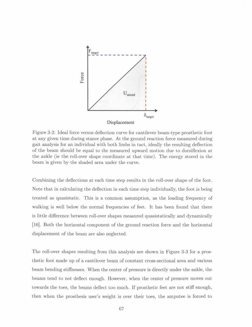
Ft get
0 I )
6 target
Displacement
Figure 3-2: Ideal force versus deflection curve for cantilever beam-type prosthetic footat any given time during stance phase. At the ground reaction force measured duringgait analysis for an individual with both limbs in tact, ideally the resulting deflectionof the beam should be equal to the measured upward motion due to dorsiflexion atthe ankle (ie the roll-over shape coordinate at that time). The energy stored in thebeam is given by the shaded area under the curve.
Combining the deflections at each time step results in the roll-over shape of the foot.
Note that in calculating the deflection in each time step individually, the foot is being
treated as quasistatic. This is a common assumption, as the loading frequency of
walking is well below the normal frequencies of feet. It has been found that there
is little difference between roll-over shapes measured quasistatically and dynamically
[16]. Both the horizontal component of the ground reaction force and the horizontal
displacement of the beam are also neglected.
The roll-over shapes resulting from this analysis are shown in Figure 3-3 for a pros-
thetic foot made up of a cantilever beam of constant cross-sectional area and various
beam bending stiffnesses. When the center of pressure is directly under the ankle, the
beams tend to not deflect enough. However, when the center of pressure moves out
towards the toes, the beams deflect too much. If prosthetic feet are not stiff enough,
then when the prosthesis user's weight is over their toes, the amputee is forced to
67
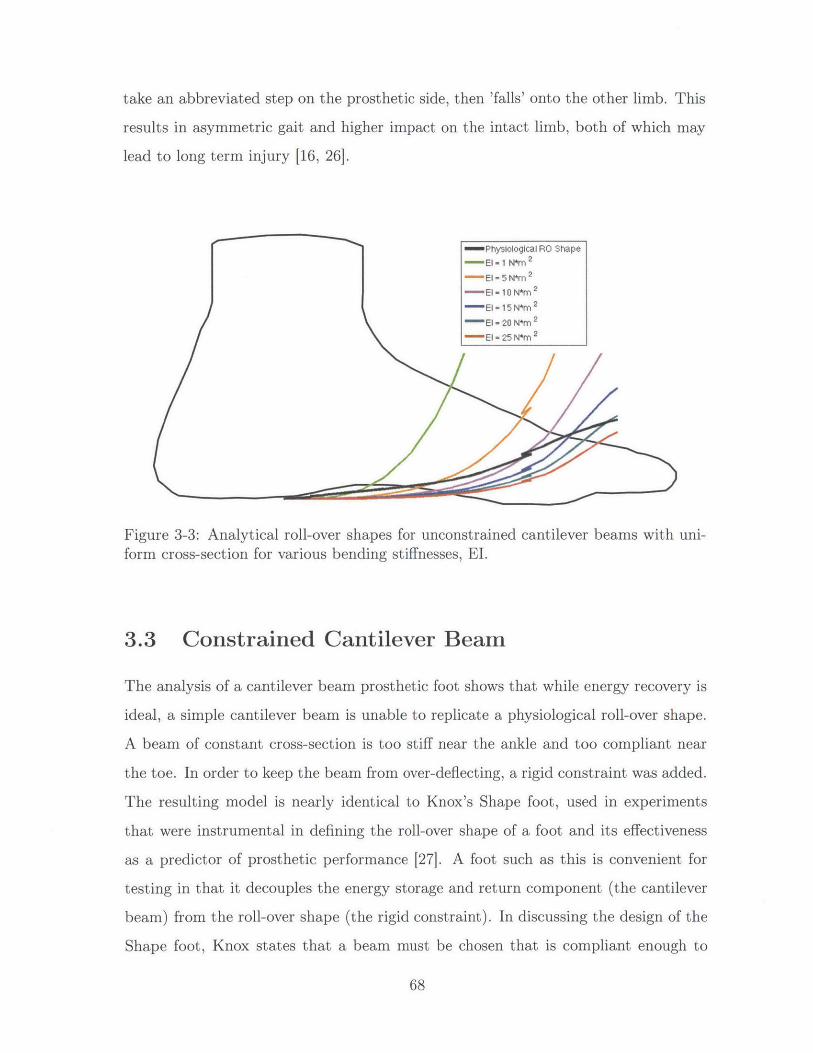
take an abbreviated step on the prosthetic side, then 'falls' onto the other limb. This
results in asymmetric gait and higher impact on the intact limb, both of which may
lead to long term injury [16, 261.
- Physiological RO Shape-El- 1 N*m 2
-El = 5 N*m 2
-El - 10 N*m 2
El = 15 N*m 2
El - 20 N*m 2-El - 25 N*m 2
Figure 3-3: Analytical roll-over shapes for unconstrained cantilever beams with uni-form cross-section for various bending stiffnesses, El.
3.3 Constrained Cantilever Beam
The analysis of a cantilever beam prosthetic foot shows that while energy recovery is
ideal, a simple cantilever beam is unable to replicate a physiological roll-over shape.
A beam of constant cross-section is too stiff near the ankle and too compliant near
the toe. In order to keep the beam from over-deflecting, a rigid constraint was added.
The resulting model is nearly identical to Knox's Shape foot, used in experiments
that were instrumental in defining the roll-over shape of a foot and its effectiveness
as a predictor of prosthetic performance [27]. A foot such as this is convenient for
testing in that it decouples the energy storage and return component (the cantilever
beam) from the roll-over shape (the rigid constraint). In discussing the design of the
Shape foot, Knox states that a beam must be chosen that is compliant enough to
68

conform to the roll-over shape; thus the amount of energy stored is limited. This
thesis builds on Knox's work in quantifying this trade-off between energy storage and
roll-over shape.
If the beam is too compliant, it comes in contact with the constraint at a ground
reaction force less than the measured physiological ground reaction force magnitude.
If the beam is too stiff, the deflection of the beam is less than the deflection required
to match the gait data, and the roll-over shape is not achieved. Neither of these
situations are ideal energetically, as both store less energy than a beam that deflects
exactly the desired amount under the specified load. Figure 3-4 illustrates this con-
cept.
target
0
6 targetDisplacement
(a) Too Compliant
I II II II II II II II II II I
UstoredI II II I
actual
Displacement
(b) Too Stiff
UU
0LU
target
target
Ustor..~ d
6target
Displacement
(c) Ideal
Figure 3-4: Comparison of strain energy stored for beams that are too stiff, toocompliant, and ideal. If the beam is either too stiff or too compliant, less strain energyis stored than if the beam were the exact stiffness. If the beam is too compliant(a), it makes contact with the constraint before the full expected load has beenapplied. After making contact, the force continues to increase, but the deflectiondoes not. If the beam is too stiff (b), it never reaches the necessary deflection forthe physiological roll-over shape. If the beam has the correct compliance (c), theconstraint is not necessary, and the maximum possible energy is stored. Note thatthe subscript "target" here refers to values that were obtained in gait analysis of anindividual with no amputations and exhibiting typical gait [451.
69
UT
4

3.3.1 Finite Element Model
When a constraint is added, using beam bending equations to calculate the roll-over
shape and strain energy stored in the beam is no longer the most effective method,
as it is time consuming and requires certain simplifications. Finite element analysis
is quicker and provides more realistic results.
A finite element model consisting of a flexible cantilever beam, a rigid contact surface
defined by the physiological roll-over shape calculated from published gait data [45]
above the beam, and a horizontal rigid contact surface below the beam representing
the ground was created. The foot was approximated as a 2D solid in plane stress.
Figure 3-5 shows the FE model in detail together with a physical prototype of the
foot.
The thickness and width of the beam were set to 0.01 m and 0.07 m. Six different
bending stiffnesses, selected based on the analysis of unconstrained cantilever beams
in Section 3.2, were investigated: 1 N-m 2 , 5 N-m2 , 10 N-m2, 15 N-m2, 20 N-m 2, and
25 N-m 2 . To achieve these, the elastic modulus was varied. Because the analysis pre-
sented herein deals exclusively with beam bending and does not discuss stress within
the beam, the elastic modulus and the second area moment of inertia never appear
independently of one another in the governing equations (3.1) and (3.2) and thus
either one could be varied to produce the same results, so long as bending stiffness
remains the same.
3.3.2 Method
As with the unconstrained beam in Section 3.2, the foot was modeled quasistatically
at several time intervals. The smallest natural frequency of the beam as found by
FEA in the condition with the lowest bending stiffness was 16.51 Hz, which is signif-
70

A rt =*
D
NA
1-
* ~ I.*,.~.*
(a) Detailed FE Model
D
NA
(b) FE Model overlaid on picture of a prototype prosthetic foot
Figure 3-5: FE model of cantilever beam and rigid contact surfaces representing theground and the mechanical constraint following a physiological roll-over shape
71

icantly higher than the loading frequency during walking of approximately 1 Hz, so
this is again verified as a safe assumption.
Roll-over Shape
The portion of the cantilever beam which would be rigidly attached to the ankle was
oriented with respect to the ground in 12 different positions covering the range of
orientations from heel strike to toe-off. In these 12 different positions, the angle be-
tween the theoretical ankle-knee segment and the ground was -14.6* (corresponding
to heel strike), -0.3', 3.5', 5.60, 7.40, 9.4 , 11.30, 13.20, 16.1 0, 19.80, 22.90, and 26.80
(corresponding to toe-off). These positions were selected by taking the orientations
of the ankle-knee segment from the published gait data at approximately equal time
steps. Note that fewer orientations were used from heel strike to toe off because there
is very little deflection in the cantilever beam when the center of pressure is behind
the ankle - knee segment due to the short moment arm; thus the roll-over shape is
linear, and only two data points are required to characterize the roll-over shape in this
regime. The focus was instead on the foot-flat to toe off regime, where the curvature
of the roll-over shape is much higher.
In each of these orientations, a vertical displacement was imposed on the portion
of the beam that would be fixed to the ankle (here-on referred to simply as the ankle
of the model). As this displacement increased, the sum vertical reaction force acting
on the beam from the ground contact surface also increased. The model was used to
find the vertical displacement of the ankle which resulted in a sum vertical reaction
force equal to the vertical ground reaction force reported in the published gait analysis
corresponding to that particular ankle orientation. This represented the actual shape
the beam would take if someone were to take a step on it and replicate the published
ground reaction forces. Once this position was known, the center of pressure on the
ground contact surface in the FE model could be calculated and rotated into the
ankle-knee reference frame to produce a data point in the predicted roll-over shape,
72

as shown in Figure 3-6.
An(e Position
Center of Pressure
(a)
(b)
Figure 3-6: Illustration of obtaining a point on the roll-over shape plot using an FEmodel of a single instant during walking. The center of pressure and the ankle positioncoordinates are measured in the lab reference frame (a), then rotated and translatedinto an ankle-knee reference frame (b). When this is done for several time steps andplotted on the ankle-knee reference frame, the resulting curve is the roll-over shape.
In order to determine the vertical displacement at the ankle that results in the target
net ground reaction force, a displacement was imposed in 1 mm increments. The
resulting net ground reaction force was listed at each of these increments. When
the target GRF was between two of these incremental net GRFs, the loading was
refined such that ten vertical displacements of 0.1 mm were applied between these
two displacements. This process was repeated with decreasing displacement step sizes
until the GRF at one of the imposed displacements was within 15 N of the target GRF.
73

When a displacement was prescribed for which the FEA GRF was within 15 N of the
target GRF, the reaction force magnitude and the X- and Y-coordinate of each node
along the portion of the foot that was in contact with the ground contact surface were
exported to a MATLAB script, which returned the location of the center of pressure.
This, together with the position and orientation of the ankle at that same prescribed
displacement, was used to find the coordinates of a single point on the roll-over shape
for that beam stiffness.
In addition to the twelve points resulting from the FEA results in each orientation,
a point was added to the roll-over shape directly below the ankle, in line with the
ankle - knee segment. At this location the cantilever beam is rigidly attached to the
rest of the foot-ankle complex, so when the center of pressure acts at this point, the
beam does not undergo any deflection and thus performing a finite element analysis
was unnecessary.
In order to quantify how close the roll-over shape for a given beam stiffness was
to the physiological roll-over shape, an R2 value was calculated comparing the RO
shape from FEA to the physiological RO shape. Each of the twelve foot/ankle orien-
tations yield both an x- and a y-coordinate of a point on the roll-over shape for that
model. In order to compare these to the physiological roll-over shape, the points on
the physiological curve were extrapolated from the data at the x-coordinates of each
of the points resulting from FEA. The R2 values were calculated by comparing the
y-coordinates at these extrapolation points to the y-coordinates from the FEA.
Energy Storage
As stated in (3.3) and further illustrated in Figure 3-4, the strain energy stored in a
cantilever beam is equal to the integral of the force over the applied displacement, or
the area under the curve on a graph of force versus displacement. In the FE model
here discussed, the only compliant component is the cantilever beam, which is mod-
eled as a purely elastic element. This means that no energy is dissipated, and the
74

amount of energy stored in the beam is dependent only on the shape of the beam at
a given time, not on the loading that occurred on the way to that shape. This means
that the same vertical loading that was applied to the model to obtain the roll-over
shape can also be used to obtain the energy stored in the beam, so long as the final
position and shape of the beam is the same as it would be during gait. This would
not be true if a foam cosmesis or any other dissipator were included in the model.
While the energy stored in the beam can be calculated at each of the 12 orienta-
tions of the foot analyzed, the amount of energy stored just before push-off is the
most important, as this is the theoretical amount of energy available to be returned
as the user propels himself forward. Thus the energy stored in the beam in the po-
sition corresponding to this instant during stance was used as an indication of the
energy storing capabilities of the beam. This is similar to the test defined by the
American Orthotic and Prosthetic Association (AOPA) used by manufacturers to de-
termine whether a prosthetic foot falls into the flexible or dynamic keel categories, in
which the foot is loaded at an angle of 20 degrees relative to a surface, similar to the
orientation of the foot relative to the ground immediately prior to push-off [3].
To calculate this energy storage, a vertical displacement is imposed at the ankle of
the same FE model previously discussed in the final orientation, which corresponds
to push-off. At each incremental vertical displacement, the resulting net vertical
reaction force on the beam from the ground contact surface was recorded. The dis-
placement at the exact target GRF was linearly interpolated. The energy stored in
the beam is equal to the integral of these net vertical reaction forces over the applied
displacements, which was approximated from the data using the trapezoidal method
of numerical integration.
75

3.3.3 Results
The roll-over shapes resulting from the finite element model as described above for
three of the beam bending stiffnesses analyzed (EI = 1 N-m 2, 15 N-m 2 , and 25 N-n 2 )
are shown in Figure 3-7. As expected, the more compliant beams mimic the physio-
logical roll-over shape more closely, as they are more likely to make contact with the
rigid constraint under the applied loads.
0.04
0.02 P
00
0
a.
0 +
-0.02-
-0.04-
-0.06-
- -0.08
0a -0.1
-0.05 0 0.05 0.1Proximal - Distal Coordinate [m]
0.15
Figure 3-7: Roll-over shapes resulting from finite element analysis for three of thebeam bending stiffnesses considered. Beams with lower stiffnesses were found tomimic the physiological roll-over shape more closely, since they were more likely tomake contact with the rigid constraint defined by the physiological roll-over shape.The stiffer beams do not deflect all the way to the rigid constraint and thus do notreplicate the curvature of the physiological roll-over shape as well.
The force versus displacement curves immediately prior to push-off for each of the
bending stiffnesses investigated are shown in Figure 3-8. The area under these curves
is the amount of energy stored and available for return for beams of the given bending
76
- Physiological Rollover ShapeEl = 1 N*m 2
--- El = 15 N*m 2
El = 25 N*m 2
+ Ankle Location
-0.12-
-0.14 -

stiffnesses. The behavior described above in Section 3.3 and illustrated in Figure 3-4
is clearly exhibited - the most compliant beam makes contact with the rigid constraint
at a much lower than desired ground reaction force, at which point the force increases
rapidly while the beam is unable to bend any further, resulting in a transition to a
nearly vertical force versus deflection curve. Meanwhile, the stiffer beams reach the
target GRF without ever reaching the target displacement; this explains the discrep-
ancy between the roll-over shape of the stiffer cantilever beam foot models and the
physiological roll-over shape shown in Figure 3-7.
These results, along with the earlier theoretical discussion of a constrained cantilever
beam-type foot, suggest that feet that fit this model exhibit a trade-off between roll-
over shape and energy storage - very compliant beams fit the roll-over shape well
but do not store much energy, whereas very stiff beams store more energy, but do
not deflect enough to mimic the physiological roll-over shape. This trade-off is best
illustrated by comparing the R2 value of the model RO shape to the energy stored as
a function of bending stiffness (Figure 3-9).
3.4 Discussion
The above results show the trade-off between energy storage capacity and obtaining
a physiological roll-over shape for solid ankle, flexible keel prosthetic feet. Without
a mechanical constraint, a simple cantilever beam stores the most energy, but the
roll-over shapes either have too large of a radius, which is not optimal metabolically
[1], or do not extend far enough in the anterior direction, which could likely lead to
asymmetric step length and ground reaction forces seen in other feet with roll-over
shapes that curved up too much at the toe [16, 19, 36, 26, 25].
77

0.005 0.01 0.015 0.02 0.025 0.03Displacement [m]
0.035 0.04 0.045
Figure 3-8: Force versus deflection curves calculated from FE model for constrainedcantilever beam-type feet of various bending stiffness immediately prior to push-off. The energy stored in the beam and thus available for return during late stancephase is equal to the area under these curves. Feet that are too compliant reachthe mechanical constraint at forces much lower than the target GRF (the horizontaldotted line), whereas feet that are too stiff never reach the target deflection (thevertical dotted line).
A mechanical constraint added to the prosthetic foot model, resulting in a model
similar to Knox's Shape foot [27], prevents the beam from over-deflecting, thus en-
forcing a roll-over shape closer to what is measured during typical walking. However,
by limiting the deflection, the constraint also detracts from potential energy storage
capacity. More compliant beams make contact with the constraint at lower ground
reaction forces, and thus exhibit the target roll-over shape almost exactly, but store
significantly less energy than stiffer beams. However, the stiffer beams do not con-
form to the target roll-over shape as well.
78
700
600
500
400
300
200
100
0Li-
Ftarget
E
-
E -E
--E
=1 1E1=5- =10- =151 = 201 = 25
'CD
0
-1000

1 n
0.9 -
0.8--6
-u 0.7-
r0.6 -&2
0.2 -
CO,
0.4-
0 ' '
0
Cz: 0.3--2
0.2-
0.1
0 5 10 15 20 25Beam Bending Stiffness [N*m 21
Figure 3-9: R2 value from comparing FE model roll-over shape to physiological roll-over shape (left axis) and strain energy stored in foot immediately prior to push-off(right axis) for each of the bending stiffnesses investigated herein. More compliantbeams match the physiological RO shape more closely, while stiffer beams store morestrain energy.
Without further information about the relative importance of ESAR and a phys-
iological roll-over shape in terms of user perception and metabolic cost, it is not
possible to optimize the bending stiffness of a flexible keel prosthetic foot. However,
from Figure 3-9, we see that the energy storage capacity increases quickly for bending
stiffnesses up to 10 N-m2, while the R2 value for fitting the target roll-over shape does
not decrease much in that range. From these results, the ideal bending stiffness is
likely at least 10 N-m2 .
In the FEA model, the thickness of the cantilever beam was left unchanged and
79
I I I I
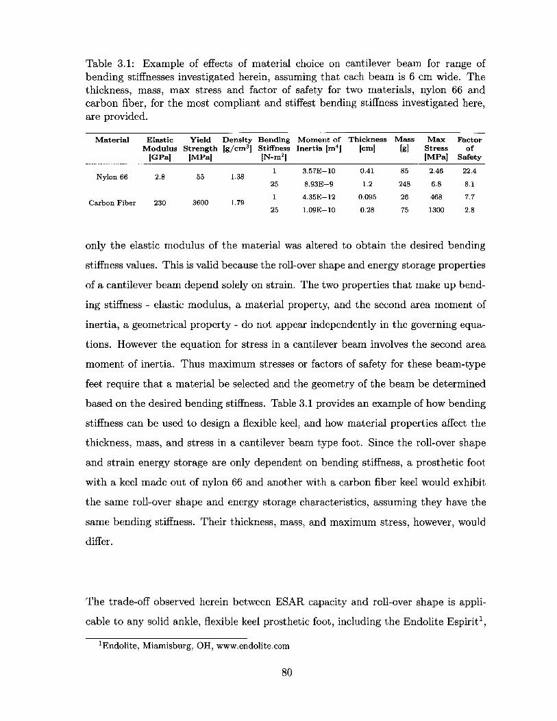
Table 3.1: Example of effects of material choice on cantilever beam for range ofbending stiffnesses investigated herein, assuming that each beam is 6 cm wide. Thethickness, mass, max stress and factor of safety for two materials, nylon 66 andcarbon fiber, for the most compliant and stiffest bending stiffness investigated here,are provided.
Elastic Yield Density Bending Moment ofModulus Strength jg/cm3] Stiffness Inertia [m4 ]
[GPa [MPa] IN-m2]
Thickness Mass Max Factor[cm] [g] Stress of
[MPa] Safety
1 3.57E-10 0.41 85 2.46 22.4Nylon 66 2.8 55 1.38
25 8.93E-9 1.2 248 6.8 8.1
Carbon Fiber 230 3600 1.79 1 4.35E-12 0.095 26 468 7.7
25 1.09E-10 0.28 75 1300 2.8
only the elastic modulus of the material was altered to obtain the desired bending
stiffness values. This is valid because the roll-over shape and energy storage properties
of a cantilever beam depend solely on strain. The two properties that make up bend-
ing stiffness - elastic modulus, a material property, and the second area moment of
inertia, a geometrical property - do not appear independently in the governing equa-
tions. However the equation for stress in a cantilever beam involves the second area
moment of inertia. Thus maximum stresses or factors of safety for these beam-type
feet require that a material be selected and the geometry of the beam be determined
based on the desired bending stiffness. Table 3.1 provides an example of how bending
stiffness can be used to design a flexible keel, and how material properties affect the
thickness, mass, and stress in a cantilever beam type foot. Since the roll-over shape
and strain energy storage are only dependent on bending stiffness, a prosthetic foot
with a keel made out of nylon 66 and another with a carbon fiber keel would exhibit
the same roll-over shape and energy storage characteristics, assuming they have the
same bending stiffness. Their thickness, mass, and maximum stress, however, would
differ.
The trade-off observed herein between ESAR capacity and roll-over shape is appli-
cable to any solid ankle, flexible keel prosthetic foot, including the Endolite Espirit1 ,
'Endolite, Miamisburg, OH, www.endolite.com
80
Material
Ossur Flex-Foot Axia2 , Ossur Vari-Flex, Quantum Foot3 , SAFE foot, Kingsley Flat-
tie4 , Kingsley Strider, College Park Tribute 5, College Park Celsus, Trulife Seattle
Energy6 , Trulife Seattle NaturalFlex, and the Shape&Roll Foot7 . Consider a hy-
pothetical foot similar to the Flex-Foot, for example. The Flex-Foot mechanically
behaves in the same way as this model - dorsiflexion is mimicked with a cantilever
beam made out of carbon fiber. However, rather than using a rigid constraint to
prevent over deflection when the center of pressure is under the toes, a second beam
is engaged through a viscoelastic medium, effectively increasing the stiffness. The
result is similar to what is shown in Figure 3-8 - when the foot is in a given position
and lowered towards the floor, the vertical force versus deflection curve will have a
shallow slope in the beginning, when most of the motion is coming from the single
cantilever beam, then turn towards a much steeper slope as the second cantilever
beam is engaged and stiffens the foot. With this stiffening, the Flex-Foot is able to
replicate the physiological roll-over shape [16], and also store and return energy.
Because the Flex-Foot has a roll-over shape that is nearly identical to a physio-
logical roll-over shape [16], a change in beam bending stiffness in either direction will
result in a worse roll-over shape. However if the primary beam in the Flex-Foot were
stiffer, based on trends observed through this analysis, the foot would store slightly
more strain energy at the expense of roll-over shape as shown conceptually in Fig-
ure 3-10. If the primary beam were less stiff, the roll-over shape of the Flex-Foot
would overshoot the physiological roll-over shape, resulting in too much dorsiflexion
and a 'drop-off' effect, and store less energy. Based on the positive responses to the
Flex-Foot, the foot exhibits a good balance in the trade-off between energy storage
and roll-over shape.
20ssur, Reykjavik, Iceland, www.ossur.com3 Ortho-Europe, Oxfordshire, UK, www.ortho-europe.com4 Kingsley Mfg. Co., Costa Mesa, CA, www.kingsleymfg.com5College Park Industries, Warren, MI, www.college-park.com6 Trulife, Dublin, Ireland, www.trulife.com7The 'Shape&Roll' Prosthetic Foot: I. Design and Development of Appropriate Technology for
Low-Income Countries [36]
81

Ftarget
Ugained
Ustored
6 target
Displacement
Figure 3-10: Theoretical representation of force versus displacement curve for a pros-thetic foot similar to the Flex-Foot, which engages a second beam to effectively stiffenthe keel. The Flex-Foot has been found to have a roll-over shape that matches a phys-iological roll-over shape almost perfectly; thus changing the stiffness of the beam ineither direction would result in a worse roll-over shape. However, by stiffening thebeam, or making the slope steeper on the force versus deflection slope, the foot canstore more mechanical strain energy at the expense of roll-over shape. The greenregion shows the potential energy gained with a stiffer cantilever beam.
The analysis presented in this section does have some limitations. The roll-over shapes
are found by supplying as an input the center of pressure, ground reaction force, and
ankle orientation data as measured and published for a subject with typical gait.
These roll-over shapes are what would result if that were the case. Persons with am-
putations do not exhibit typical gait, but the objective here is to design a foot such
that, given typical inputs, the outputs enable typical gait throughout the rest of the
limb.
The energy stored and available for return here represents a best-case scenario. The
beam is treated as linear elastic, and thus there is no energy lost to dissipation through
viscoelastic elements, such as a foam cosmesis. Since this condition is the same for
each of the bending stiffnesses investigated, the trends observed are still valid. It
should also be noted that all mentions of energy storage in this work refer to me-
82
chanical strain energy stored in the cantilever beam. This is the total amount of
mechanical energy available to the user from the prosthesis. Ideally, this energy is
released in a constructive manner, reducing the mechanical energy required from the
person using the prosthesis, which is correlated to metabolic energy.
All analysis performed in this work was done using a set of published gait data
for a single subject with typical gait. The roll-over shapes and energy storage calcu-
lated herein could equally be found using the loading conditions defined in ISO 22675,
which comes from normative data for typical gait [23]. However, ISO 22675 does not
provide any information about where the center of pressure between the foot and the
ground surface should be at any given time, and therefore does not allow calculation
of a normative roll-over shape to which to compare the FE results. The roll-over
shape also could not be compared to the standard of a circle with a radius 30% of
the leg length, as no information is known about leg lengths for ISO 22675 loading.
Thus a single set of gait data was used rather than the more normative data in the
ISO standard.
Further work is required to determine the effects of the mechanical properties here in-
vestigated to biomechanical gait parameters, metabolic cost, and subjective ranking.
Other factors, such as perception of stability, are likely also dependent on bending
stiffness and will affect the performance of the prosthetic foot.
3.5 Prototype Testing
In order to determine how users would respond to a prosthetic foot that exhibited a
physiological roll-over shape and energy storage and return by means of a mechanically
constrained cantilever beam, a proof-of-concept prototype was built and tested using
human subjects and a COUHES approved protocol. Nylon 66 was selected as the
material for the cantilever beam, as it has a high yield strength to elastic modulus
83

ratio, which makes it an effective material for compliant mechanisms due to high
strains at failure. The nylon beam was fixed to the bottom of a wooden block using
four threaded inserts and machine screws to provide the reaction moment necessary to
rigidly constrain the beam such that the assumed boundary conditions were accurately
reflected. Nylon beams of different thicknesses were made such that the bending
stiffness was approximately 5 N-m2 , 10 N-M2 , 15 N-m2, 20 N-in 2 and 25 N-m 2.
3.5.1 Method
Before testing was done using subjects with amputations, the investigator fixed the
prototype to the bottom of pseudo prosthesis boots. The boots restrict ankle motion
so that the only motion achieved is that of the prosthetic feet. This gives persons
without amputations an opportunity to experience an approximation of what it feels
like to walk using prosthetic feet. This was done a) to verify the safety of the pros-
thetic feet, after mechanical testing had already suggested that the feet were safe
at loads well above what was expected, and b) to experience effects of the different
beam stiffnesses that were not captured by the analysis. It was quickly realized that
the more compliant beams felt less stable than stiffer beams, in agreement with the
literature [10, 43]. For this reason, a bending stiffness of 20 N-M 2 was selected for
testing with persons with amputations at the BMVSS facility in Jaipur, India. Note
that this perception of stability was not investigated in prior analysis, and is likely
correlated with the rate of forward progression of the center of pressure.
Two subjects who were visiting BMVSS to replace worn out prosthetic limbs were
recruited for the study. Both had unilateral transtibial amputations due to trauma
and were otherwise healthy. The first subject was 62 years old and had a body mass
of 65 kg. The second was 21 years old and also had a body mass of 65 kg. Both had
been using limbs from BMVSS for over a year. Because the purpose of this test was
merely to receive preliminary feedback on an early stage prototype to inform further
development, the small sample size of two was not a problem. After a new socket was
made and fitted to each of the subjects according to the protocol typically used at
84
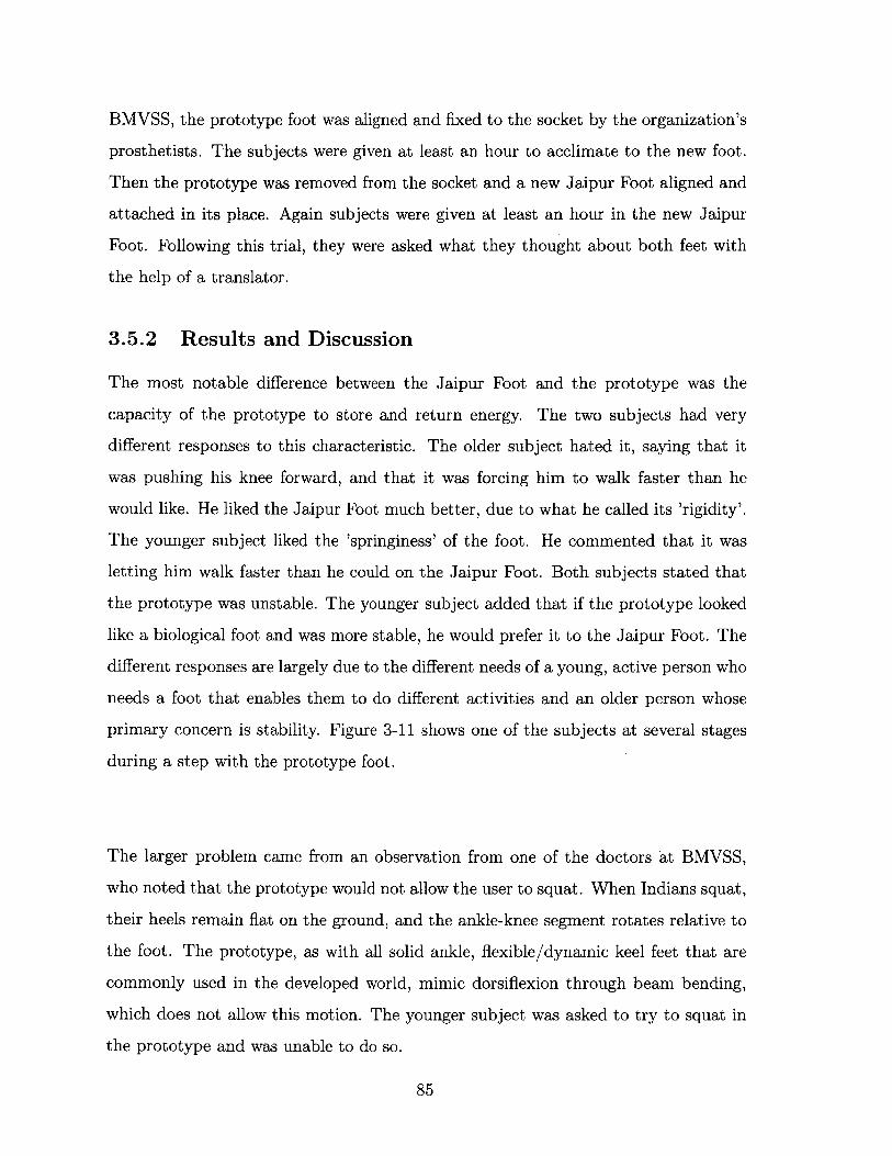
BMVSS, the prototype foot was aligned and fixed to the socket by the organization's
prosthetists. The subjects were given at least an hour to acclimate to the new foot.
Then the prototype was removed from the socket and a new Jaipur Foot aligned and
attached in its place. Again subjects were given at least an hour in the new Jaipur
Foot. Following this trial, they were asked what they thought about both feet with
the help of a translator.
3.5.2 Results and Discussion
The most notable difference between the Jaipur Foot and the prototype was the
capacity of the prototype to store and return energy. The two subjects had very
different responses to this characteristic. The older subject hated it, saying that it
was pushing his knee forward, and that it was forcing him to walk faster than he
would like. He liked the Jaipur Foot much better, due to what he called its 'rigidity'.
The younger subject liked the 'springiness' of the foot. He commented that it was
letting him walk faster than he could on the Jaipur Foot. Both subjects stated that
the prototype was unstable. The younger subject added that if the prototype looked
like a biological foot and was more stable, he would prefer it to the Jaipur Foot. The
different responses are largely due to the different needs of a young, active person who
needs a foot that enables them to do different activities and an older person whose
primary concern is stability. Figure 3-11 shows one of the subjects at several stages
during a step with the prototype foot.
The larger problem came from an observation from one of the doctors at BMVSS,
who noted that the prototype would not allow the user to squat. When Indians squat,
their heels remain flat on the ground, and the ankle-knee segment rotates relative to
the foot. The prototype, as with all solid ankle, flexible/dynamic keel feet that are
commonly used in the developed world, mimic dorsiflexion through beam bending,
which does not allow this motion. The younger subject was asked to try to squat in
the prototype and was unable to do so.
85

Figure 3-11: Subject taking a step with the proof-of-concept prototype prostheticfoot at BMVSS headquarters in Jaipur
3.6 Conclusion
This chapter presented an analysis of a simple model of a solid ankle, flexible keel
prosthetic foot using beam bending theory and FE analysis. It has been shown that a
single unconstrained cantilever beam is insufficient to mimic a physiological roll-over
shape. When a mechanical constraint is added, a trade-off becomes evident between
roll-over shape and energy storage - as beams become stiffer, the amount of strain
energy stored and available for return increases, but the roll-over shape departs from
the target physiological shape. This work presents a framework for understanding
the effect of bending stiffness on the mechanics of a solid ankle flexible keel prosthetic
86

foot that facilitates both evaluation of existing prosthetic feet and design of new feet.
Further work is required to connect those mechanical properties to gait parameters.
A prototype prosthetic foot was built based on the analysis done herein and tested
first using pseudo-prosthesis boots, then by two subjects with amputations in India.
The initial testing with the pseudo-prosthesis boots showed that an important factor
not investigated in the FE analysis was perception of stability. This is likely due to the
rate of forward progression of the center of pressure. Consequently, a bending stiff-
ness of 20 N-m2 , which is higher than stiffnesses suggested by the analysis performed
herein, was used for subject testing to provide stability. The 62 year old subject dis-
liked the energy storage and return aspect of the foot, while the 21 year old subject
liked it. Both subjects stated that the foot was unstable. However, the solid ankle
does not allow the dorsiflexion required for squatting, and thus this technology, while
promising in theory, is inappropriate for the context of BMVSS. Future prosthetic
feet for India must have rotational compliance at the ankle to permit squatting.
87

88

Bibliography
[1] P. G. Adamczyk, S. H. Collins, and A. D. Kuo. The advantages of a rolling foot
in human walking. The Journal of Experimental Biology, 209(Pt 20):3953-63,
Oct. 2006.
[2] P. G. Adamczyk and A. D. Kuo. Mechanical and energetic consequences of
rolling foot shape in human walking. The Journal of experimental biology, 216(Pt
14):2722-31, July 2013.
[3] American Orthotic and Prosthetic Association. Aopa prosthetic foot project re-
port. Technical report, American Orthotic and Prosthetic Association, Septem-
ber 2010.
[4] S. K. Au, H. Herr, J. Weber, and E. C. Martinez-Villalpando. Powered ankle-foot
prosthesis for the improvement of amputee ambulation. Conference proceedings
: ... Annual International Conference of the IEEE Engineering in Medicine and
Biology Society. IEEE Engineering in Medicine and Biology Society. Conference,
2007:3020-6, Jan. 2007.
[5] D. G. Barth, L. Schumacher, and S. S. Thomas. Gait analysis and energy cost of
below-knee amputees wearing six different prosthetic feet. Journal of Prosthetics
and Orthotics, 4(2):63-75, 1992.
[6] X. Bonnet, H. Pillet, P. Fod6, F. Lavaste, and W. Skalli. Finite element mod-
elling of an energy-storing prosthetic foot during the stance phase of transtibial
amputee gait. Journal of Engineering in Medicine, 226(1):70-75, 2011.
89

[7] G. R. Colborne, S. Naumann, P. E. Longmuir, and D. Berbrayer. Analysis of
mechanical and metabolic factors in the gait of congenital below knee amputees:
A comparison of the SACH and Seattle Feet. American Journal of Physical
Medicine & Rehabilitation, 71(5):272-78, 1992.
[8] S. H. Collins and A. D. Kuo. Controlled energy storage and return prosthesis
reduces metabolic cost of walking. In Proc. on ISB XXth Congress and the
American Society of Biomechanics Annual Meeting, page 804, Cleveland, Ohio,
2003.
[9] C. Curtze, A. L. Hof, H. G. van Keeken, J. P. K. Halbertsma, K. Postema,
and B. Otten. Comparative roll-over analysis of prosthetic feet. Journal of
Biomechanics, 42:1746-1753, 2009.
[101 N. P. Fey, G. K. Klute, and R. R. Neptune. The influence of energy storage
and return foot stiffness on walking mechanics and muscle activity in below-knee
amputees. Clinical Biomechanics, 26:1025-1032, 2011.
[11] R. Figueroa. Using FE for Dynamic Energy Return Analysis of Prosthetic Feet
during Design Process. In 25th Southern Biomedical Engineering Conference
2009, IFMBE Proceedings 24, pages 289-292, 2009.
[12] R. S. Gailey, M. A. Wenger, M. Raya, N. Kirk, K. Erbs, P. Spyropoulos, and
M. S. Nash. Energy expenditure of trans-tibial amputees during ambulation
at self-selected pace. Prosthetics and orthotics international, 18(2):84-91, Aug.
1994.
[13] E. G. Gonzalez, P. J. Corcoran, and R. L. Reyes. Energy expenditure in below-
knee amputees: correlation with stump length. Archives of physical medicine
and rehabilitation, 55(3):111-119, Mar. 1974.
[14] A. H. Hansen and D. S. Childress. Effects of shoe heel height on biologic rollover
characteristics during walking. Journal of Rehabilitation Research & Develop-
ment, 41(4):547-554, 2004.
90

[15] A. H. Hansen and D. S. Childress. Effects of adding weight to the torso on
roll-over characteristics of walking. The Journal of Rehabilitation Research and
Development, 42(3):381, 2005.
[16] A. H. Hansen, D. S. Childress, and E. H. Knox. Prosthetic foot rollaARover
shapes with implications for alignment of trans A tibial prostheses. Prosthetics
and Orthotics International, 24(3):205-215, Jan. 2000.
[17] A. H. Hansen, D. S. Childress, and E. H. Knox. Roll-over shapes of human
locomotor systems: effects of walking speed. Clinical Biomechanics, 19:407-414,
2004.
[18] A. H. Hansen, M. R. Meier, P. H. Sessoms, and D. S. Childress. The effects of
prosthetic foot roll-over shape arc length on the gait of trans-tibial prosthesis
users. Prosthetics and orthotics international, 30(3):286-99, Dec. 2006.
[19] A. H. Hansen, M. Sam, and D. S. Childress. The Effective Foot Length Ratio:
A Potential Tool for Characterization and Evaluation of Prosthetic Feet. JPO
Journal of Prosthetics and Orthotics, 16(2):41-45, Apr. 2004.
[20] C. Hofstad, H. van der Linde, J. van Limbeek, and K. Postema. Prescription of
prosthetic ankle-foot mechanisms after lower limb amputation ( Review ). The
Cochrane Library, 1, 2009.
[21] M.-J. Hsu, D. H. Nielsen, S.-J. Lin-Chan, and D. Shurr. The effects of pros-
thetic foot design on physiologic measurements, self-selected walking velocity,
and physical activity in people with transtibial amputation. Archives of physical
medicine and rehabilitation, 87(1):123-9, Jan. 2006.
[22] M. J. Hsu, D. H. Nielsen, H. J. Yack, and D. G. Shurr. Physiological mea-
surements of walking and running in people with transtibial amputations with
3 different prostheses. The Journal of orthopaedic and sports physical therapy,
29(9):526-33, Sept. 1999.
91

[23] International Organization for Standardization. ISO 22675: Prosthetics - Testing
of ankle-foot devices and foot units - Requirements and test methods, 2006.
[24] T. S. Jang, J. J. Lee, D. H. Lee, and Y. S. Yoon. Systematic methodology for the
design of a flexible keel for energy-storing prosthetic feet. Medical & Biological
Engineering & Computing, 39:56-39, 2001.
[25] E. Klodd, A. Hansen, S. Fatone, and M. Edwards. Effects of prosthetic foot
forefoot flexibility on oxygen cost and subjective preference rankings of unilateral
transtibial prosthesis users. Journal of Rehabilitation Research & Development,
47(6):543-552, 2010.
[26] E. Klodd, A. Hansen, S. Fatone, B. P. 0. Hons, and M. Edwards. Effects of
prosthetic foot forefoot flexibility on gait of unilateral transtibial prosthesis users.
Journal of Rehabilitation Research & Development, 47(9):899-910, 2010.
[27] E. H. Knox. The role of prosthetic feet in walking. PhD thesis, Northwestern
University, 1996.
[28] J. F. Lehmann, R. Price, S. Boswell-Bessette, A. Dralle, and K. Questad. Com-
prehensive analysis of dynamic elastic response feet: Seattle Ankle/Lite Foot
versus SACH foot. Archives of physical medicine and rehabilitation, 74(8):853-
861, Aug. 1993.
[29] J. F. Lehmann, R. Price, S. Boswell-Bessette, A. Dralle, K. Questad, and B. J.
DeLateur. Comprehensive analysis of energy storing prosthetic feet: Flex Foot
and Seattle Foot Versus Standard SACH foot. Archives of physical medicine and
rehabilitation, 74(11):1225-1231, Nov. 1993.
[30] P. A. Macfarlane, D. H. Nielsen, D. G. Shurr, and K. Meier. Gait comparisons
for below-knee amputees using a Flex-Foot versus a conventional prosthetic foot.
Journal of Prosthetics and Orthotics, 3(4):150-161, 1991.
[31] P. A. Macfarlane, D. H. Nielsen, D. G. Shurr, K. G. Meier, R. Clark, J. Kerns,
M. Moreno, and B. Ryan. Transfemoral amputee physiological requirements:
92

Comparisons between SACH foot walking and Flex-Foot walking. Journal of
Prosthetics and Orthotics, 9(4):138-143, 1997.
[321 T. McGeer. Passive Dynamic Walking. The International Journal of Robotics
Research, 9(2):62-82, Apr. 1990.
[33] D. H. Nielsen, D. G. Shurr, J. C. Golden, and K. Meier. Comparison of energy
cost and gait efficiency during ambulation in below-knee amputees using different
prosthetic feet - A Preliminary report. Journal of Prosthetics and Orthotics,
1(1):24-31, 1989.
[34] J. Perry and S. Shanfield. Efficiency of dynamic elastic response prosthetic feet.
Journal of Rehabilitation Research, 30(1):137-143, 1993.
[35] C. M. Powers, L. Torburn, J. Perry, and E. Ayyappa. Influence of prosthetic foot
design on sound limb loading in adults with unilateral below-knee amputations.
Archives of physical medicine and rehabilitation, 75(7):825-829, July 1994.
[361 M. Sam, D. S. Childress, A. H. Hansen, M. R. Meier, S. Lambla, E. C. Grahn,
and J. S. Rolock. The 'Shape&Roll' prosthetic foot: I. design and development
of appropriate technology for low-income countries. Medicine, Conflict and Sur-
vival, 24(4):294-306, 2004.
[37] M. Sam, A. H. Hansen, and D. S. Childress. Characterisation of prosthetic
feet used in low-ARincome countries. Prosthetics and Orthotics International,
28(2):132-140, Jan. 2004.
[38] T. Schmalz, S. Blumentritt, and R. Jarasch. Energy expenditure and biome-
chanical characteristics of lower limb amputee gait: the influence of prosthetic
alignment and different prosthetic components. Gait & posture, 16(3):255-63,
Dec. 2002.
[39] R. D. Snyder, C. M. Powers, C. Fontaine, and J. Perry. The effect of five pros-
thetic feet on the gait and loading of the sound limb in dysvascular below-knee
93

amputees. Journal of Rehabilitation Research & Development, 32(4):309-315,
1995.
[40] L. Torburn, J. Perry, E. Ayyappa, and S. Shanfield. Below-knee amputee gait
with dynamic elastic response prosthetic feet : a pilot study . Journal of Reha-
bilitation Research & Development, 27(4):369-384, 1990.
[41] L. Torburn, C. M. Powers, R. Guiterrez, and J. Perry. Energy expenditure during
ambulation in dysvascular and traumatic below-knee amputees: A comparison
of five prosthetic feet. Journal of Rehabilitation Research and Development,
32(2):111-119, 1995.
[42] H. A. Underwood, C. D. Tokuno, and J. J. Eng. A comparison of two prosthetic
feet on the multi-joint and multi-plane kinetic gait compensations in individuals
with a unilateral trans-tibial amputation. Clinical Biomechanics, 19(6):609-616,
2004.
[43] J. D. Ventura, G. K. Klute, and R. R. Neptune. The effects of prosthetic an-
kle dorsiflexion and energy return on below-knee amputee leg loading. Clinical
Biomechanics, 26(3):298-303, Mar. 2011.
[44] R. L. Waters, J. Perry, D. Antonelli, and H. Hislop. Energy cost of walking of
amputees: the influence of level of amputation The Influence of Walking of Level
of Amputees: of Amputation. Journal of Bone & Joint Surgery, 58:42-46, 1976.
[45] D. A. Winter. Biomechanics and Motor Control of Human Movement. John
Wiley & Sons, Inc, fourth edition edition, 2009.
94

Chapter 4
Conclusion
The motivation of this work is to design a low cost, mass-manufacturable prosthetic
foot for Indian persons with amputations. This thesis presented a literature on dif-
ferent metrics that can be used to compare prosthetic feet, a general analysis of how
beam bending stiffness affects roll-over shape and energy storage and return capacity
for a mechanically constrained solid ankle cantilever beam-type prosthetic foot, and
the construction and testing of a proof-of-concept prototype.
Chapter 1 introduces the Jaipur Foot and provides detailed motivation for the work
done herein. It describes a preliminary semi-structured interview done with the help
of a translator with visitors at the BMVSS headquarters in Jaipur, India. From this
interview it was learned that there were very few complaints about the current Jaipur
Foot. Most of the issues were due to the socket. The most noticeable contribution
that could be made for the persons using the Jaipur Foot would be improving the
durability. A set of design requirements is presented as elucidated from these inter-
views, conversations with doctors and the founder at BMVSS, and from the literature
review and analysis presented in Chapters 2 and 3.
Chapter 2 explains the wide variety of methods and metrics that can be used to
quantify differences between prosthetic feet. In industry, a set of tests developed by
the American Orthotic & Prosthetic Association are used to characterize the mechan-
95
ical behavior of prosthetic feet primarily to facilitate the reimbursement process for
insurance companies. These tests are based on existing products and do not attempt
to make any recommendations. ISO 22675 is used to measure the durability and
safety of prosthetic feet. In academia, the types of prosthetic foot comparisons can
be broken down into mechanical comparisons, gait analysis comparisons, metabolic
comparisons, and subjective comparisons. Mechanical measurements are the easiest
to use during early stage design, but also the furthest removed from the ultimate
objective of the foot. Both subjective and metabolic comparisons are used to evalu-
ate existing prosthetic feet, but are not directly useful for design. Gait analysis falls
somewhere in the middle. From the review of literature, two parameters emerge as
necessary, but not sufficient: roll-over shape and energy storage and return.
Chapter 3 reduces a prosthetic foot to a very simple model of a cantilever beam at-
tached to a solid ankle, and rigidly constrained to prevent over-deflection. It presents
an analysis of how bending stiffness affects both roll-over shape and energy storage.
For compliant beams, the roll-over shape replicates the physiological roll-over shape
very closely, but stores little energy. For stiff beams, the reverse is true. This was
validated using FEA. In order to determine the ideal bending stiffness, information
is required about the relative value of each of these properties to the user of the pros-
thesis. A proof-of-concept prototype prosthetic foot was built to obtain feedback on
one such foot. While a few positive comments were made by one of the subjects, the
foot does not allow squatting, and thus other options will need to be pursued.
Future Work
In order to achieve the 30* of dorsiflexion required for squatting, a rotational joint at
the ankle is required. The same analysis that was performed in finding the roll-over
shape of an unconstrained cantilever beam in Section 3.2 can be done on a model
of a rigid foot with a single degree of freedom rotational joint at the ankle. The
stiffness of this joint can be optimized to best mimic a physiological roll-over shape
and, if necessary, a rigid constraint can be added to prevent over deflection. In this
96

case, some of the conclusions from the analysis performed in this thesis will still be
valid - when the joint is in contact with the rigid constraint, it will limit the amount
of energy stored in the joint. Once this stiffness is optimized, a proof of concept
prototype should be built as quickly as possible to perform initial user testing, as was
done with the mechanically constrained cantilever beam prosthetic foot discussed
herein. If the performance of the foot is satisfactory, the mass should be minimized
and the mechanism should be made in such a way that it fits within the envelope
of a foot, so that it may be enclosed in foam to provide weather resistance and the
appearance of a biological foot. The analysis presented in Chapter 3 is still valid,
however, and can be used to evaluate other feet, or to design a foot for a different
demographic that doesn't require squatting.
97