Design and development of measurement JIG system · Design of clamping jig was done according to...
9
Design and development of measurement JIG system Jiří Němec Department of Machining Technology, Faculty of Mechanicla Enginering, University of West Bohemia, 301 00 Pilsen, Czech republic. E-mail: [email protected] 1 Introduction The clamping jig, which is described in this paper, is designed for three axis measuring machine (Fig. 1). This machine is placed at the indoor laboratory of the Manufacturing Engineering Group. The machine is con- sisted from two main parts. These are measuring part (portal with measuring probe) and clamping part (table with granite desk). The main disadvantage of clamping part of the machine is insufficient number of treaded holes at granite desk. There are only nine treaded holes with metric tread M6. Distances between the holes are large. It means that the holes in the granite desk cannot be effectively used for clamping of measured parts. This fact is catch in the picture with improvised fixing of vice (Fig. 1 - right side). Fig. 1: 3axis measuring machine Trimek (right side: detail of improvised fixing of vice) 2 Design of the clamping jig Design of clamping jig was done according to modern trend at clamping devices. Clamping jig was designed like reconfigurable device. Automation of the clamping device was rejected, because measuring of the part is not common. The concept of the clamping jig is consisted from a platform, which is fixed on the granite desk. This platform allows clamp lot of different clamping features, for example vice, centre pins, clamps etc. 2.1 Platform It was made more types of the platforms, but main idea is still same. The first concept was used lot of treaded holes, which allows tightening of clamping features into it. This concept is showed in the next picture (Fig. 2) STROJÍRENSKÁ TECHNOLOGIE – PLZEŇ 2015 174
Transcript of Design and development of measurement JIG system · Design of clamping jig was done according to...

Design and development of measurement JIG system
Jiří Němec Department of Machining Technology, Faculty of Mechanicla Enginering, University of West Bohemia, 301 00 Pilsen, Czech republic. E-mail: [email protected]
1 Introduction
The clamping jig, which is described in this paper, is designed for three axis measuring machine (Fig. 1). This machine is placed at the indoor laboratory of the Manufacturing Engineering Group. The machine is con-sisted from two main parts. These are measuring part (portal with measuring probe) and clamping part (table with granite desk). The main disadvantage of clamping part of the machine is insufficient number of treaded holes at granite desk. There are only nine treaded holes with metric tread M6. Distances between the holes are large. It means that the holes in the granite desk cannot be effectively used for clamping of measured parts. This fact is catch in the picture with improvised fixing of vice (Fig. 1 - right side).
Fig. 1: 3axis measuring machine Trimek (right side: detail of improvised fixing of vice)
2 Design of the clamping jig
Design of clamping jig was done according to modern trend at clamping devices. Clamping jig was designed like reconfigurable device. Automation of the clamping device was rejected, because measuring of the part is not common. The concept of the clamping jig is consisted from a platform, which is fixed on the granite desk. This platform allows clamp lot of different clamping features, for example vice, centre pins, clamps etc.
2.1 Platform
It was made more types of the platforms, but main idea is still same. The first concept was used lot of treaded holes, which allows tightening of clamping features into it. This concept is showed in the next picture (Fig. 2)
STROJÍRENSKÁ TECHNOLOGIE – PLZEŇ 2015
174

Fig. 2: Concept of the platform with treaded holes
Disadvantage of this solution is fixed location of the holes. Position of the clamping feature can be set only by steps. These steps are determined by dimensions between the holes. This fact great reduce possibilities of the universal use of the jig.
The problem with fixed location of the treaded holes can be solved by using T groove and T nuts. This fea-ture allows random setting of the position of the clamping features at one way. T grooves allow changing of position in the longitudinal direction of groove. But it is impossible designed T grooves close to each other much, because small space between grooves not allows placing of the clamping features. More T groove allows change position only in one way. When perpendicular T grooves will be used, it is not place clamping feature in to the intersection of grooves. There is marked space of intersection by red colour in the picture Fig. 3 on the right side. Another disadvantage of the T grooves is that tightening force must be done for fixing position of the clamping feature.
Fig. 3: Concept of the platform with perpendicular T grooves (right side: red colour mark place where clamping
feature cannot be fixed)
Final design of the platform was created by the connection both concepts. One way T grooves were used and the trough thread holes were designed in the spaces between grooves. The dimensions of the treaded holes were designed by the tread hole in the T nuts. Dimension of the used tread is M8. Because preparing of the clamping jig will be done outside of the working space of the measure machine, it was designed two platforms which have different dimensions. The platform marked "L" (Fig. 4) has dimensions 300x285x25 mm and is fixed by four screws M6 with conical head to granite desk.
STROJÍRENSKÁ TECHNOLOGIE – PLZEŇ 2015
175

Fig. 4: Finally design of the bigger platform which is marked "L"
The platform marked "S" has dimensions 225x200x25 mm. This smaller platform is fixed to granite desk by two screws. These screws are same as in previous case. The smaller platform is suitable for smaller number of the clamping features or for measuring smaller parts. The smaller platform is mainly designed for fixing of the vice and the side support.
2.2 Columns
Other important clamping feature, which was necessary to designed, was support for centring and positioning pins. The main requirement to columns was changeability of the centring or the positioning pins and height ad-justment of the columns. Two concepts were designed. The first concept use standardized part and the second concept was aimed to bigger height adjustment of support columns.
The first design concept is consisted from both sided bolt, extended nut for connecting two bolts and the cen-tring of positioning feature with tread. This concept is shown with T nut in the picture Fig. 5. Positioning and fixing of the column in space is done by nut and washer. If the nut is tightened, distance between T nut and T groove is defined and position of the column is defined too. This concept has one big disadvantage. This type of column is not accurate in the repeated clamping of the other measured parts, because there is tolerance in treads between the bolt and extended nut. This disadvantage could be replaced by delimiting tube, but this solution does not allow simply height adjustment of the column. The unusually shape of the T groove is shown it the picture Fig. 5. This shape was designed for magnification of range of the height adjustment. However this concept al-lows only small range of height adjustment. The range is only few millimetres.
Fig. 5: Concept of the Column from standard parts
STROJÍRENSKÁ TECHNOLOGIE – PLZEŇ 2015
176
The second solution of the column is more variable than the first solution, but special parts have to be fabri-cated. The column is consisting of two main parts. There are leading pin and adjustment sheath. Height of col-umn is set by ejecting of the sheath on the pin. The position of the sheath on the pin is secured by two bolts (Fig.6). The leading pin allows height adjustments in the range of 32 mm. Small groove is designed on the lead-ing pin and this groove marks the maximal ejecting of the sheath. The rectangular rib on the leading pin is used for tightening of the column to the platform.
Fig. 6: Settable column with maximal ejecting of the sheath
The both concepts were judged and the concept with the leading pin was chosen. This concept allows bigger height adjustment and it is more accurate than the first concept with standard parts. Small disadvantage of the selected concept is the necessity of fabricating of the special parts.
2.3 Centring and positioning pins
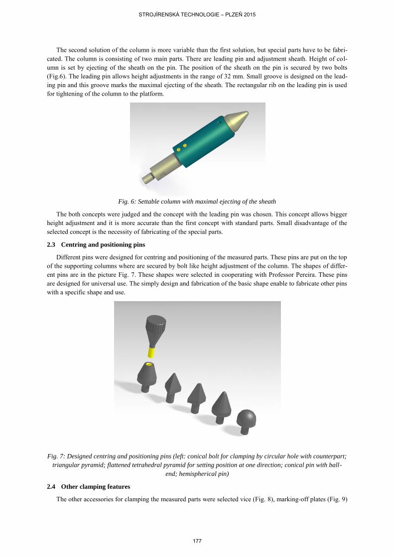
Different pins were designed for centring and positioning of the measured parts. These pins are put on the top of the supporting columns where are secured by bolt like height adjustment of the column. The shapes of differ-ent pins are in the picture Fig. 7. These shapes were selected in cooperating with Professor Pereira. These pins are designed for universal use. The simply design and fabrication of the basic shape enable to fabricate other pins with a specific shape and use.
Fig. 7: Designed centring and positioning pins (left: conical bolt for clamping by circular hole with counterpart;
triangular pyramid; flattened tetrahedral pyramid for setting position at one direction; conical pin with ball-
end; hemispherical pin)
2.4 Other clamping features
The other accessories for clamping the measured parts were selected vice (Fig. 8), marking-off plates (Fig. 9)
STROJÍRENSKÁ TECHNOLOGIE – PLZEŇ 2015
177

and clamps. These accessories allow clamping many different measured parts.
Fig. 8: Model of the vice, which is used for clamping of the measured parts now
The marking-off plates were selected for clamping cylindrical parts. The marking-off plates size 70 with four grooves were selected, because they are more universal. The marking-off plates are manufactured in couples and fabricating of these parts are technologically difficult. Hence these components will be purchased from company PILSEN TOOLS s.r.o. This company fabricate special cutting tools, measuring devices and clamping jigs.
Fig. 9: Model of marking-off plate size 70 with four grooves from company PILSEN TOOLS s.r.o.
The side support was designed for setting of the position of the measured parts (Fig. 10). This side support is fixed on the platform by bolts. This component was designed for two possibilities of fixing on the platform. The side support can be fixed horizontal or vertical. Manufacturing of this component is not necessary, because other components to are able to substitute this function.
STROJÍRENSKÁ TECHNOLOGIE – PLZEŇ 2015
178
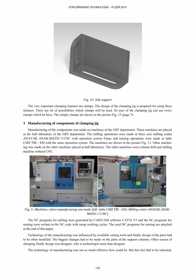
Fig. 10: Side support
The very important clamping features are clamps. The design of the clamping jig is prepared for using these features. There are lot of possibilities which clamps will be used. So user of the clamping jig can use every clamps which he have. The simply clamps are shown in the picture Fig. 13 (page 7).
3 Manufacturing of components of clamping jig
Manufacturing of the components was made on machines of the GEF department. These machines are placed at the hall laboratory of the GEF department. The milling operations were made at three axis milling centre ANAYAK ANAK-MATIC-7-CNC with operation system Fanuc and turning operations were made at lathe CMZ TBI - 450 with the same operation system. The machines are shown in the picture Fig. 11. Other machin-ing was made on the other machines placed at hall laboratory. The other machines were column drill and milling machine without CNC.
Fig. 5: Machines, where manufacturing was made (left: lathe CMZ TBI - 450; Milling centre ANAYAK ANAK-
MATIC-7-CNC)
The NC programs for milling were generated by CAD/CAM software CATIA V5 and the NC programs for turning were written in the NC code with using working cycles. The used NC programs for turning are attached at the end of this paper.
Technology of the manufacturing was influenced by available cutting tools and finally design of the parts had to be often modified. The biggest changes had to be made on the parts of the support columns. Other reason of changing finally design was designer, who is technologist more than designer.
The technology of manufacturing was not so much effective how could be. But this fact had to be tolerated,
STROJÍRENSKÁ TECHNOLOGIE – PLZEŇ 2015
179

because piece production was realised. Individual components were made from aluminium alloy, because this material is more available for the contracting entity. But using of this soft aluminium alloy significantly affects durability of the machining components. It is not so big problem in case of the components for the support col-umns, because fabricating of these components is simple and available for user of the clamping jig. But the big-gest could be with the main component of the clamping jig. The most important component of the jig is platform. The fabricating of this part is more difficult and lot of material is necessary for producing of this part.
4 Examples of clamping jig configurations
There are shown some configurations of the clamping jig. These pictures are for better imagination, how this clamping jig could be used. The configuration with vice and side support is in the picture Fig. 12, the configura-tion with marking-off plates and side support is in the picture Fig. 13 and the configuration with support columns is in the picture Fig. 14. These configurations are prepared for different measured part.
Fig. 6: The configuration of the clamping jig with vice
Fig. 7: The configuration of the clamping jig with marking-off plates
STROJÍRENSKÁ TECHNOLOGIE – PLZEŇ 2015
180

Fig. 15: The configuration of the clamping jig with the supports columns
5 Conclusion
The clamping jig was designed based on the specification of the user. This device is suitable for repeated clamping medium series of the measured parts in the three axis measuring machine. The clamping jig extends the use of this measuring machine. The clamping device can be prepared outside of the working space of the machine, so the measuring machine is not burdened by long preparation times. The clamping jig is universal and allows fixing many parts with different shapes and dimensions. The repeatability of the measuring was request and the finally design allows good repeatability. But, when configuration of the clamping jig is done, it is very difficult reset the jig to previous configuration. If it will be necessary to measure same part, the measuring pro-grams have to be prepared for small change of position of the measured part.
All important components of the clamping jig were made from aluminium alloy and user of the clamping jig has all manufacturing documentation including CNC programs. So when some piece will be damaged, it can be simply replaced. All fabricated parts of clamping jig are shown it picture Fig. 16.
Fig. 8 The fabricated parts
The production of the prototype clamping jig cost 2939.91€. If the clamping jig will be fabricated at mass production 500 pieces per year, cost per one piece decrease to 769.64€.
STROJÍRENSKÁ TECHNOLOGIE – PLZEŇ 2015
181

Abstract
Artilce: DESIGN AND DEVELOPMENT OF MEASUREMENT JIG SYSTEM
Authors: Ing. Jiří Němec
Workplace: Department of Machining Technology, University of West Bohemia, Pilsen, Czech republic
Keywords: clamping; jig system; 3D measuring machine; manufacturing
Following article describe design and production of the universal clamping jig for clamping measured parts in to three axis measuring machine. This clamping jig was designed and produced under exchange program Erasmus. Department Manufacturing Engineering Group (GEF) University of Vigo (Spain) and Department of Machining Technology (KTO) University of West Bohemia (Czech Republic) cooperated at this project. The clamping jig was created for extension possibilities of fixing of the measured parts in to work space of the meas-uring machine. Current state was insufficient. The worker of the department GEF specified requirements to the new clamping jig. The finally design of the clamping jig had to be universal and had to allow measuring parts in large series.
Individual concepts were designed based on the specification and consultations with the project initiator. The optimal design was chosen from these concepts. The concepts are described in this article. Machines and tools, which are used for fabricating part of the jig, are described in the article. Results of the project are summa-rized in the conclusion.
STROJÍRENSKÁ TECHNOLOGIE – PLZEŇ 2015
182