Design and Development of Liquid Nitrogen Storage Vessel...
62
Design and Development of Liquid Nitrogen Storage Vessel Using ASME Boiler and Pressure Vessel Code By RAJENDRA KUMAR PRAHARAJ National Institute of Technology, Rourkela, Odisha (INDIA) -769008 A thesis submitted for the degree of Master of Technology in Mechanical Engineering (Specialization: Machine Design and Analysis) May-2015
Transcript of Design and Development of Liquid Nitrogen Storage Vessel...
Design and Development of Liquid Nitrogen
Storage Vessel Using ASME Boiler and
Pressure Vessel Code
By RAJENDRA KUMAR PRAHARAJ
National Institute of Technology, Rourkela,
Odisha (INDIA) -769008
A thesis submitted for the degree of Master
of Technology in Mechanical Engineering
(Specialization: Machine Design and
Analysis)
May-2015

Design and Development of Liquid Nitrogen Storage Vessel
Using ASME Boiler and Pressure Vessel Code
A thesis submitted in partial fulfillment of the requirements for award of the
degree of
Master of Technology in
Mechanical Engineering
(Machine Design and Analysis)
By
RAJENDRA KUMAR PRAHARAJ
(Roll No. 213ME1388)
Under the supervision of
Department of Mechanical Engineering
National Institute of Technology Rourkela- 769008
Odisha (INDIA)
Mr. Chandan Samal
Senior Design Manager
I-design Engineering Solution Ltd.
Pune- 412207
Prof. P.K. Ray
Department of Mechanical Engineering
National Institute of Technology
Rourkela - 769008
P a g e | i
National Institute of Technology, Rourkela
Odisha (INDIA) -769008
CERTIFICATE
This is to certify that the thesis entitled, “Design and Development of Liquid Nitrogen Storage
Vessel Using ASME Boiler and Pressure Vessel Code” submitted by Mr. Rajendra Kumar
Praharaj in partial fulfillment of the requirements for the award of Master of Technology Degree
in Mechanical Engineering (specialization of Machine Design and Analysis) at National Institute
of Technology, Rourkela, Odisha (INDIA) is an authentic work carried out by him under our
supervision and guidance. To the best of our knowledge, the matter embodied in the thesis has not
been submitted to any other University/ Institute for the award of any degree or diploma.
Date:
Place:
Prof. P.K. Ray
Department of Mechanical
Engineering
National Institute of Technology
Rourkela - 769008
Mr. Chandan Samal
Senior Design Manager
I-design Engineering Solution Ltd.
Pune- 412207
P a g e | ii
CONTENTS
INDEX Page No.
CERTIFICATE i
CONTENTS ii
ACKNOWLEDGEMENT vi
ABSTRACT vii
LIST OF FIGURES viii
LIST OF TABLES ix
Chapter No. Title Page No.
Chapter 1 1. Introduction 1
1.1 Objective of the study 3
1.2 Basic components of Liquid nitrogen storage container 3
Chapter 2 2. Literature Survey 4
2.1 Failure theories for pressure vessel design 4
2.1.1 Maximum principal stress theory 5
2.1.2 Maximum Shear stress theory 5
2.2 Broad outlines in ASME Code 7
2.3 Factor causing the pressure vessel failure 8

P a g e | iii
2.4 Concept behind the development of liquid nitrogen container 9
2.5 Project work plan chart 10
Chapter 3 3. Design of Nitrogen container 11
3.1 Reference codes & Standards 11
3.2 Design data for Nitrogen vessel 11
3.3 Design internal pressures in calculation. 12
3.4 Hydrostatic pressure calculation 12
3.5 Material of Construction and stress values 13
3.6 Design of Outer cylindrical shell (Nitrogen Vessel) Thickness
under Internal Pressure
14
3.7 Design of Inner cylindrical shell (Nitrogen Vessel) Thickness un-
der External Pressure
15
3.8 Design of front bolted flange (Nitrogen Vessel) Thickness 15
3.9 Design of rear welded flange (Nitrogen Vessel) Thickness 16
3.10 Design of inner flange (Nitrogen Vessel) Thickness 17
3.11 Design of outer flange (Nitrogen Vessel) Thickness 19
3.12 Design of thickness of nozzle wall under internal pressure 21
Chapter 4 4. Design of Vacuum vessel 23
4.1 Reference Codes & Standards 23
4.2 Design data for Vacuum vessel 23
4.3 Calculation of Design internal pressures. 24
4.4 Hydrostatic Test Pressure Calculation 24

P a g e | iv
4.5 Material of Construction Evaluation chart as per ASME section II 25
4.6 Design of Outer cylindrical shell (Vacuum Vessel) Thickness un-
der External Pressure
25
4.7 Design of Inner cylindrical shell (Vacuum Vessel) Thickness un-
der Internal Pressure
26
4.8 Design of Outer cylindrical shell (Vacuum vessel ) thickness un-
der internal pressure
27
4.9 Design of Front Bolted Flange (Vacuum Vessel) Thickness 28
4.10 Design of Rear Welded Flange (Vacuum Vessel) Thickness 29
4.11 Design of Inner Flange (Vacuum Vessel) Thickness 29
4.12 Design of Outer Flange (Vacuum Vessel) Thickness 31
4.13 Openings in vacuum vessel 34
4.14 Thickness of nozzle wall under internal pressure (N1) 34
4.15 Thickness of nozzle wall under internal pressure (N2) 35
4.16 Stress analysis of lifting lugs for vacuum vessel 36
Chapter 5 5.0 Thermal Design of Nitrogen vessel container 37
5.1 Conduction Heat Load Calculation 38
5.1.1 Conduction Heat Load due to G10 Support 39
5.1.2 Conduction Heat load due to neck region of Cylindrical Surface 40
5.2 Radiation Heat Load Calculation 40
5.2.1 Radiation Hat Load due to Falt end of Vacuum chamber 41
5.2.2 Radiation Heat Load due to Cylindrical surface of the vacuum
chamber
41
P a g e | v
5.2.3 Radiation Heat Load due to flat end of neck portion 42
5.2.4 Radiation Heat Load due to Cylindrical surface of the neck
portion
42
Chapter 6 6. CAD and Finite Element Analysis 44
6.1 Finite element Analysis Plots 46
6.2 Nitrogen chamber welds joint details 47
6.3 Vacuum chamber welds joint details 48
Chapter 7 7. Fabrication and Assembly Of Vessel 49
7.1 Experimental tests setup 50
Chapter 8 8. Discussion and Conclusion 51
Chapter 9 9. REFERENCES 52

P a g e | vi
Acknowledgement
When one starts any work it will be surely finished, for successful completion of any work, it
requires hard work and determination in a right direction. Behind successful completion of my
work there are many people who made it possible and whose constant guidance and encouragement
crowned all the efforts with success. Therefore, I would like to take this opportunity to express my
sincere and heartfelt gratitude to all those who made this project possible.
First of all, I am highly grateful to my supervisor, Prof. P.K.Ray, Department of Mechanical
Engineering, N.I.T Rourkela for believing in me and encouraging me in every step, and their great
support and inspiring guidance throughout the project work, thanks for helping me to make my one
of dreams comes true.
I also wish to express my deep sense of gratitude and indebtedness to Mr. Chandan Samal, Senior
Design Manager, Idesign Engineering Solution Ltd. Pune for his inspiring guidance and valuable
suggestion throughout this project work.
I would like to express my grateful thanks to Mr. Amulya Kumar Sahoo, Senior Engineer, I-
Design Engineering Solution Ltd. Pune for his kind support, and give us time for valuable
suggestion regarding project work.
I also wish to express my grateful thanks to S.S Udgata, Director, I-design Engineering Solution
Ltd. Pune for permission to do M.Tech at NIT, Rourkela.
Special thanks to my god (Maa-Baba) and family members, without their blessings and support, I
could not have reached this destination.
Last but not the least, I wish to place my deep sense of thanks to all my friends, especially to Mr.
Biswajit Sahoo for their cooperation and critical suggestion during my project works and studies.
Rajendra Kumar Praharaj
(May 2015

P a g e | vii
ABSTRACT
A pressure vessel is a closed container which is designed to store liquid or gas at a pressure or
temperature, which is different from the ambient temperature and pressure. During operation, the
pressure vessel has to withstand several induced stresses due to internal or external pressure. Thus,
for the safety purpose storage vessels has to be designed according to ASME standards and rules.
In most of the liquid nitrogen storage vessel, there was no proper control over the heat loss and
differential pressure even in static condition which leads to fatal accidents and unnecessary loss of
the LN2. Thus, it is important to design the fluid storage container such that no leakage can take
place as well as the container has to withstand desired pressure and high or low temperature.
The design mainly concerned with two chambers mounted concentrically out of which one
experiences internal pressure and other experiences external pressure with proper fixture and
connecting arrangements. The operating pressure is 0.1 MPa for both inside nitrogen storage vessel
and outside vacuum jacketed vessel. The present work explores the proper design guidelines for the
design of storage vessel which can which can withstand the differential pressure with minimum
heat loss using ASME codes and standards. ASME Boiler & Pressure vessel code (ASME Sec VIII,
Div-1, Edition 2010, Addenda 2011) has been used for the design of the vessel and materials are
selected as per ASME Sec II Part A & D (M), Edition 2010. The connecting pipes are designed as
per the ASME B 36.10. Finite Element Analysis and experimental testing have been carried out for
validation.
Keywords: ASME Code; Pressure vessel; Finite Element Analysis; Cold Shock Test; Factor of
safety; Von mises stress, Hydrostatic test, Cold Shock test,
P a g e | viii
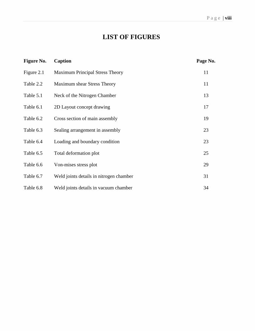
LIST OF FIGURES
Figure No. Caption Page No.
Figure 2.1 Maximum Principal Stress Theory 11
Table 2.2 Maximum shear Stress Theory 11
Table 5.1 Neck of the Nitrogen Chamber 13
Table 6.1 2D Layout concept drawing 17
Table 6.2 Cross section of main assembly 19
Table 6.3 Sealing arrangement in assembly 23
Table 6.4 Loading and boundary condition 23
Table 6.5 Total deformation plot 25
Table 6.6 Von-mises stress plot 29
Table 6.7 Weld joints details in nitrogen chamber 31
Table 6.8 Weld joints details in vacuum chamber 34
P a g e | ix
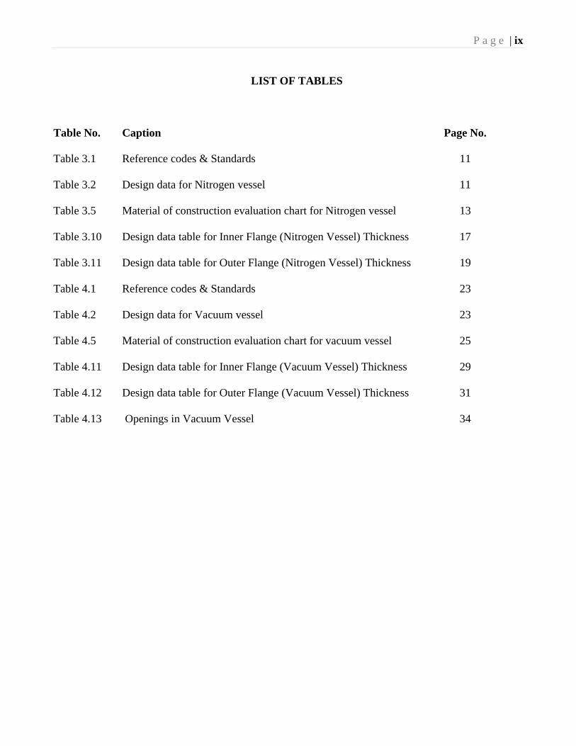
LIST OF TABLES
Table No. Caption Page No.
Table 3.1 Reference codes & Standards 11
Table 3.2 Design data for Nitrogen vessel 11
Table 3.5 Material of construction evaluation chart for Nitrogen vessel 13
Table 3.10 Design data table for Inner Flange (Nitrogen Vessel) Thickness 17
Table 3.11 Design data table for Outer Flange (Nitrogen Vessel) Thickness 19
Table 4.1 Reference codes & Standards 23
Table 4.2 Design data for Vacuum vessel 23
Table 4.5 Material of construction evaluation chart for vacuum vessel 25
Table 4.11 Design data table for Inner Flange (Vacuum Vessel) Thickness 29
Table 4.12 Design data table for Outer Flange (Vacuum Vessel) Thickness 31
Table 4.13 Openings in Vacuum Vessel 34
P a g e | 1
CHAPTER 1
INTRODUCTION
A liquid nitrogen storage vessel is a close container like pressure vessel which is designed to store
or transit fluids at a temperature and pressure which is different from ambient temperature and
pressure. Cryogen reservoir like helium, nitrogen storage container are usually have a complex ge-
ometrical structure having discontinuities and are required to work under complex loading systems
like internal pressure, external pressure, thermal loads, etc. Differential pressure is dangerous and
which causes so many accidents in the history of pressure vessel developments. The design of pres-
sure vessel does not mean the detail calculation for defining the dimensions of a member rather to
know the reasoning behind the different modes of the pressure vessel failure or the method of stress
analysis which gives the significance results and the selection of material type and its environmen-
tal behavior.
So the design of the pressure vessel involves some design parameters such as maximum safe oper-
ating pressure, corrosion allowance, minimum design material temperature, nondestructive testing
like radiography, ultrasonic testing, and pressure testing like hydrostatic test, etc. Thus design,
manufacturing, fabrication and testing of these products should follow some national standards, in-
ternational codes that provide high safety factor and taking care of these above design parameters.
Some popular codes which are used for the design of pressure vessel are ASME Boiler and Pressure
vessel Code [1], BS 5500, EN13445 etc.
Generally, pressure vessels are in the system of cylinders, spheres, ellipsoids or a combination of
these. Liquid nitrogen storage vessels are composed of a complete nitrogen containing chamber
with flange rings covered with vacuum jacketed evacuated chamber, fasteners are used for connect-
ing mating parts. When thickness is insignificant in contrast with a mean diameter (Rm/ t > 10),
vessels are designated as membrane and the stresses are developed due to the loading are called as
P a g e | 2
membrane stresses which are maybe tensile or compressive in nature and these stresses are sup-
posed to be constant across the vessel wall [2]. The membrane or wall of the pressure vessel is sup-
posed to have no confrontation to bending. When the wall of the vessel, offers resistance to bend-
ing, bending stress also developed in addition to the membrane stresses, thus in an intricate shape
vessel loaded with internal pressure, the membrane stress does not give the satisfactory idea about
the true stress- strain condition. Other factors like the effect of supports, types of end covers used
for closing the vessel, nozzles, thickness variation and external attachments like piping system all
cause uneven stress distribution in the pressure vessel. ASME Boiler and Pressure Vessel provide a
large factor of safety at the geometrical discontinuity areas like openings, nozzle intersections,
change of curvature, thickness variation etc.
The pressure vessel which is exposed to external or internal pressure, stresses are developed in the
wall of the vessel. For thick vessel state of stress is triaxial with three principal stresses [2]
Sx = Meridional stress or longitudinal stress
Sy = Latitudinal stress or Circumferential stress
Sr = Radial stress
In addition to these stresses there may be bending stress and torsion stress developed in the wall of
the vessel. For the thin cylinders, the radial stress is so small as compared to the other principal
stresses, thus radial stress can be neglected so state of stress is biaxial. But in thick vessel, radial
stress cannot be ignored, so state of stress is triaxial. Since ASME Code, Section VIII, Division 1,
is using a higher factor of safety is used in the design of the vessel to allow for the “unidentified”
stresses.
Frequent pressure vessels and boilers busted in the late 1800s and early 1900s which consequential
in the development of ASME Boiler and Pressure vessel code. In 1880, The American Society of
Mechanical Engineers was structured to support in the formulation of standard specifications for
P a g e | 3
pressure vessel and steam boilers. In the 1914 first edition of code was published that is ASME
Rules for the construction of static boilers. ASME section III [1] has specified the stress limit on the
bending and membrane stress. Hechmer and Hollinger [3, 4] has studied the stress behavior at the
nozzle - vessel intersection region and also they recommend that used 3-D finite element models to
study the stress behavior of a nozzle-to-cylinder intersection structure, the stress distribution in a
horizontal pressure vessel using Finite Element Analysis has been studied by S.M Khan [5]
1.1 Objective of the study
I. The optimal design of a pressure vessel which can withstand the specified pressure in accordance
with ASME Boiler and Pressure Vessel Code.
II. Vacuum chamber should achieve a high order evacuated vacuum environment of for increasing the
mean free path of the molecules.
III. Proper thermal design to minimize the heat loss due to evaporation of liquid nitrogen.
IV. Complete assembly should withstand the hydrostatic test, leak test in vacuum condition and cold
shock test.
1.2 Principal components of nitrogen storage assembly
I. Nitrogen vessel assembly
II. Vacuum vessel assembly
III. G10 insulation separator
IV. Multilayer insulation sheets
V. Support structure assembly
VI. Lifting lug

P a g e | 4
CHAPTER 2
2. Literature review
The broad objective of this chapter is to provide background information relating to the pressure
vessel study of the literature. . H.Mayer, H.L Stark and S. Ambrose [6] has studied the effect of
parameters like stress intensity range and principal stress range on the fatigue life of the pressure
vessel. S.V.Dubal and V.G Patil [7] has designed the horizontal pressure vessel supported on the
saddle according to the guidelines given by ASME section VIII, Div 1 and Div 2. P. Petrovic [8]
has studied the stress distribution in a cylindrical pressure vessel in which load applied at the free
end of the nozzle using Finite Element Analysis. Impact of welding residual stress on the failure of
the pressure was studied by M. Jeyakumar [9]. A comparative study between design of pressure
vessel by analysis and by formula done by A.Th. Diamantoudis and Th. Kermanidis for high
strength steel pressure vessels, [10] The identified areas of the survey include:
- Theory behind the pressure vessel design
- Approaches for design of pressure vessel as per ASME code.
- Factors causing pressure vessel failure
2.1 Failure theories for pressure vessel design
Induced stresses due to loading in any component are meaningless if these stresses are not com-
pared with proper failure theories. Thus the failure theories compare the combined stress due to
complex loading pattern with the maximum stress at the elastic limit of the simple tensile test. Gen-
erally for the pressure vessel design two important failure theories are used, these are Maximum
principal stress theory and Maximum shear stress theory. ASME code, section VIII division 1 uses
Maximum principal stress failure theory as a basis of design for pressure vessel [1]. H. Mayer, H.L
Strark and S. Ambrose [6] has studied the parameters like stress intensity range and principal stress
range on the fatigue design of the pressure vessel.
P a g e | 5
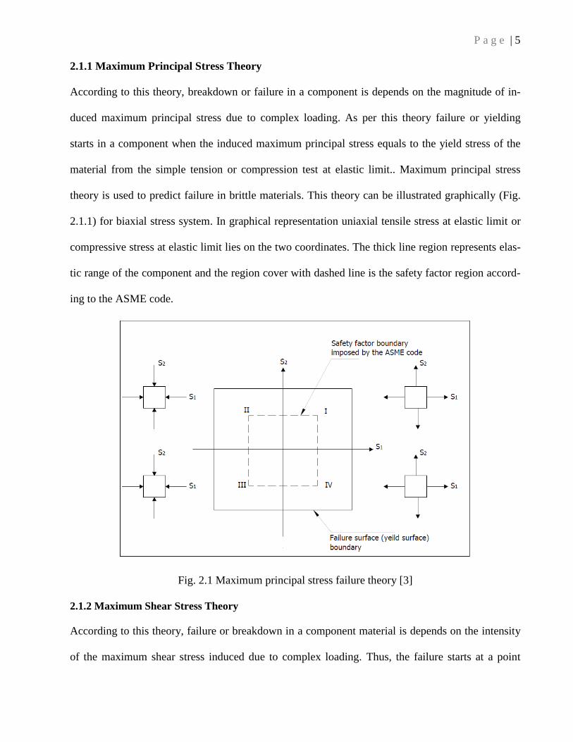
2.1.1 Maximum Principal Stress Theory
According to this theory, breakdown or failure in a component is depends on the magnitude of in-
duced maximum principal stress due to complex loading. As per this theory failure or yielding
starts in a component when the induced maximum principal stress equals to the yield stress of the
material from the simple tension or compression test at elastic limit.. Maximum principal stress
theory is used to predict failure in brittle materials. This theory can be illustrated graphically (Fig.
2.1.1) for biaxial stress system. In graphical representation uniaxial tensile stress at elastic limit or
compressive stress at elastic limit lies on the two coordinates. The thick line region represents elas-
tic range of the component and the region cover with dashed line is the safety factor region accord-
ing to the ASME code.
Fig. 2.1 Maximum principal stress failure theory [3]
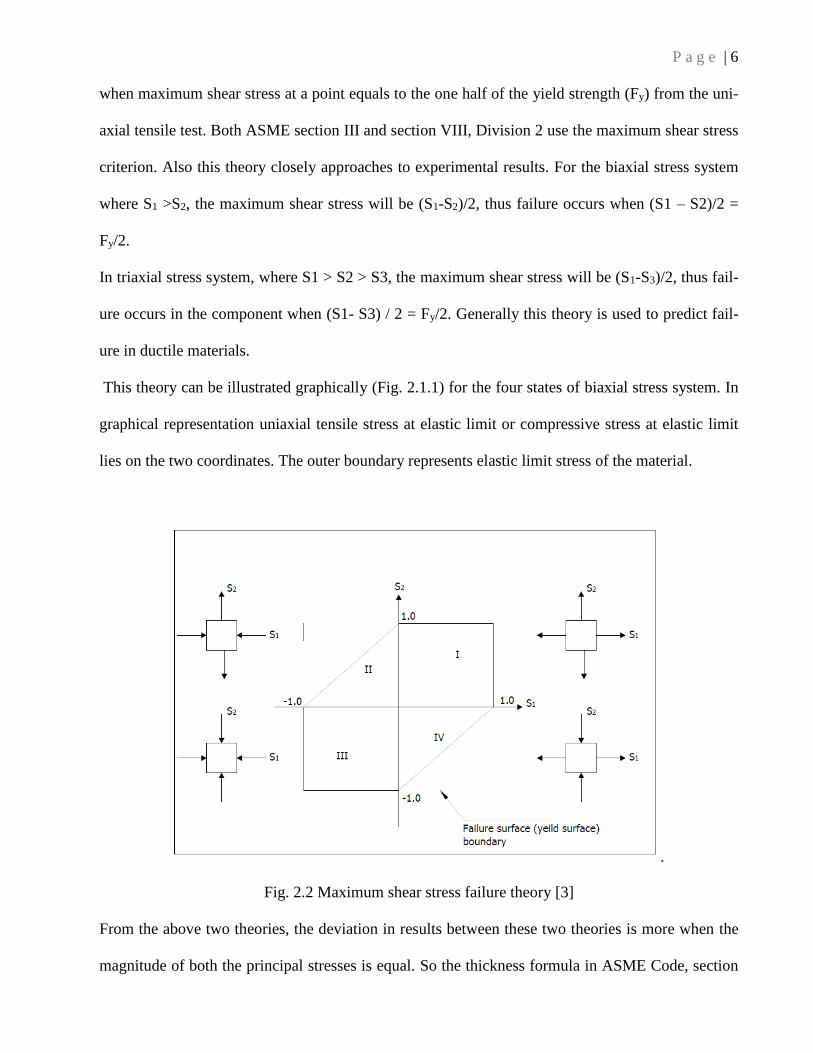
2.1.2 Maximum Shear Stress Theory
According to this theory, failure or breakdown in a component material is depends on the intensity
of the maximum shear stress induced due to complex loading. Thus, the failure starts at a point
P a g e | 6
when maximum shear stress at a point equals to the one half of the yield strength (Fy) from the uni-
axial tensile test. Both ASME section III and section VIII, Division 2 use the maximum shear stress
criterion. Also this theory closely approaches to experimental results. For the biaxial stress system
where S1 >S2, the maximum shear stress will be (S1-S2)/2, thus failure occurs when (S1 – S2)/2 =
Fy/2.
In triaxial stress system, where S1 > S2 > S3, the maximum shear stress will be (S1-S3)/2, thus fail-
ure occurs in the component when (S1- S3) / 2 = Fy/2. Generally this theory is used to predict fail-
ure in ductile materials.
This theory can be illustrated graphically (Fig. 2.1.1) for the four states of biaxial stress system. In
graphical representation uniaxial tensile stress at elastic limit or compressive stress at elastic limit
lies on the two coordinates. The outer boundary represents elastic limit stress of the material.
.
Fig. 2.2 Maximum shear stress failure theory [3]
From the above two theories, the deviation in results between these two theories is more when the
magnitude of both the principal stresses is equal. So the thickness formula in ASME Code, section
P a g e | 7
VIII, Division 1 makes a small difference whether the maximum shear stress theory or maximum
principal stress theory is used. Thus, for the thin walled pressure vessels, these two theories give
approximately the same results because in thin walled pressure vessel the radial stress is negligible
as compare to the other principal stress and that can be ignored and a biaxial stress system is as-
sumed to exist.
ASME Code, Section VIII, Division 2 and ASME Code, Section II use the stress intensity concept
which is defined as the doubled the maximum shear stress.
2.2 Broad outlines in ASME code
The complete organization of ASME code has eleven sections which are as follows:
Section I: Has rules for construction of power boiler likes electric boiler, miniature boilers, water
boiler for high temperature application and power boiler for locomotive etc.
Section II: It has four parts for material specification and selection as follows:
Part A: Specification for ferrous material
Part B: Specification for nonferrous material
Part C: Specification for filler metals, electrodes, and welding rods.
Part D: Specification for material properties like mechanical, chemical etc.
Section III: Has rules and guidelines for the components used in nuclear industries.
Section IV: Has guideline for design, fabrication and testing of steam boilers.
Section V: Has rules for nondestructive examination to detect weld defects, material defects etc.
Section VI: Has guidelines for the proper care during the operation of the heating boilers.
Section VII: Rules for the proper care during the operation of the power boilers.
Section VIII: It has three divisions according to the operating pressure ranges which has rules and
guidelines for design, fabrication, testing, and inspection of pressure vessel.

P a g e | 8
Section IX: Has rules for welding and brazing qualification also welder and brazing operator quali-
fication
Section X: Has rules for the design of reinforced plastic pressure vessel
Section XI: Provide guidelines for inspection during the operation of nuclear power plant compo-
nents.
2.3 Factors causing pressure vessel failure
The following factors are causing the premature failure of the pressure vessel so we have to take
care these factors in the design stage of the liquid nitrogen storage container.
Material:
Unsuitable selection of materials or faults in material
Design:
Due to incorrect or insufficient design data
Inaccurate design methods
Inadequate testing facilities
Manufacturing Processes:
Improper fabrication procedure, including welding
Poor quality control
Improper heat treatment process
Improper forming methods
Service:
Changes in service condition during its service period
Inexperienced or unskilled operators or maintenance personnel
Types of Failures [3]
Failure due to elastic deformation
P a g e | 9
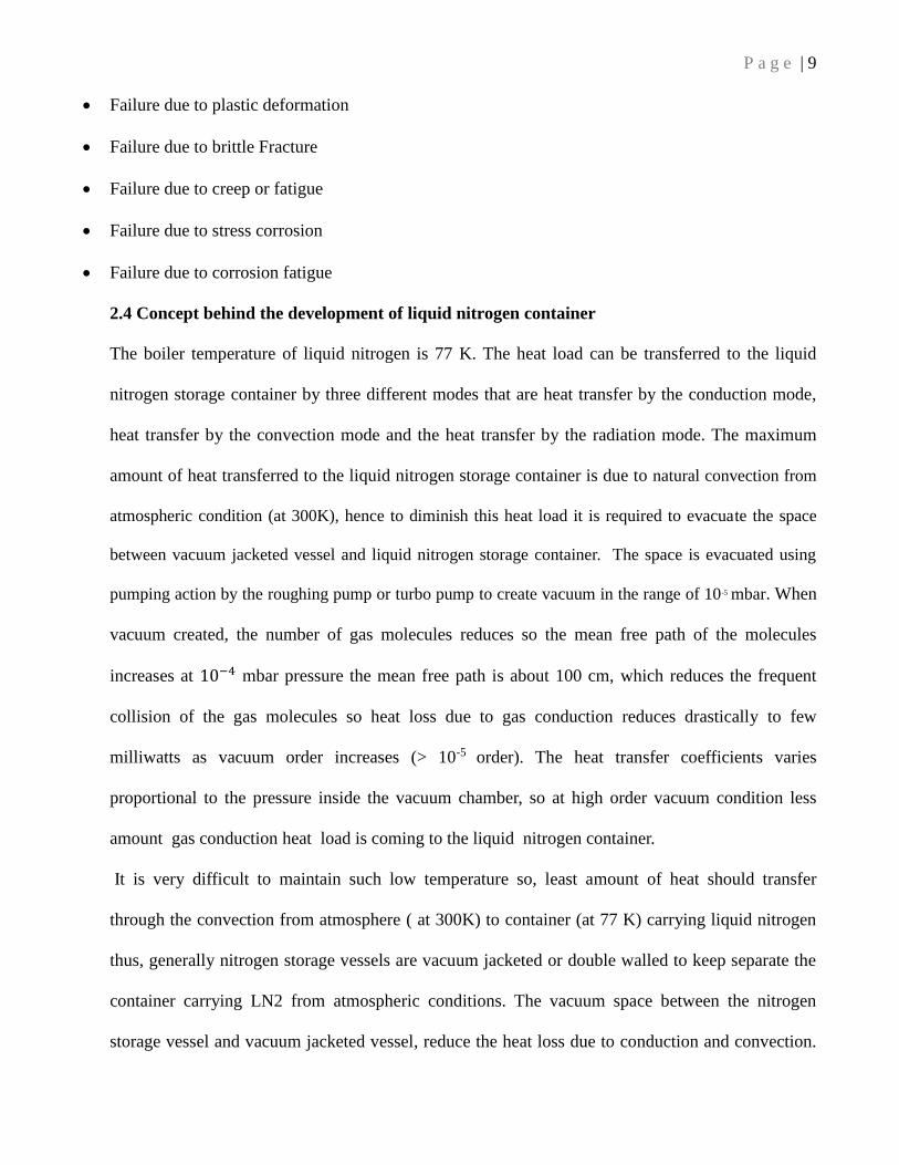
Failure due to plastic deformation
Failure due to brittle Fracture
Failure due to creep or fatigue
Failure due to stress corrosion
Failure due to corrosion fatigue
2.4 Concept behind the development of liquid nitrogen container
The boiler temperature of liquid nitrogen is 77 K. The heat load can be transferred to the liquid
nitrogen storage container by three different modes that are heat transfer by the conduction mode,
heat transfer by the convection mode and the heat transfer by the radiation mode. The maximum
amount of heat transferred to the liquid nitrogen storage container is due to natural convection from
atmospheric condition (at 300K), hence to diminish this heat load it is required to evacuate the space
between vacuum jacketed vessel and liquid nitrogen storage container. The space is evacuated using
pumping action by the roughing pump or turbo pump to create vacuum in the range of 10-5 mbar. When
vacuum created, the number of gas molecules reduces so the mean free path of the molecules
increases at 10−4 mbar pressure the mean free path is about 100 cm, which reduces the frequent
collision of the gas molecules so heat loss due to gas conduction reduces drastically to few
milliwatts as vacuum order increases (> 10-5 order). The heat transfer coefficients varies
proportional to the pressure inside the vacuum chamber, so at high order vacuum condition less
amount gas conduction heat load is coming to the liquid nitrogen container.
It is very difficult to maintain such low temperature so, least amount of heat should transfer
through the convection from atmosphere ( at 300K) to container (at 77 K) carrying liquid nitrogen
thus, generally nitrogen storage vessels are vacuum jacketed or double walled to keep separate the
container carrying LN2 from atmospheric conditions. The vacuum space between the nitrogen
storage vessel and vacuum jacketed vessel, reduce the heat loss due to conduction and convection.

P a g e | 10
Also, some multilayer insulation made of aluminum foil having high reflectivity are used to reduce
heat loss due to radiation. Some G10 insulation material having a very low thermal conductivity is
used between two vessels for reducing heat loss due to conduction.
2.5 Project Work Plan Chart
P a g e | 11
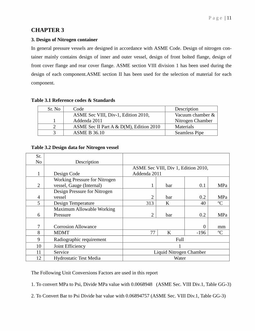
CHAPTER 3
3. Design of Nitrogen container
In general pressure vessels are designed in accordance with ASME Code. Design of nitrogen con-
tainer mainly contains design of inner and outer vessel, design of front bolted flange, design of
front cover flange and rear cover flange. ASME section VIII division 1 has been used during the
design of each component.ASME section II has been used for the selection of material for each
component.
Table 3.1 Reference codes & Standards
Sr. No Code Description
1
ASME Sec VIII, Div-1, Edition 2010,
Addenda 2011
Vacuum chamber &
Nitrogen Chamber
2 ASME Sec II Part A & D(M), Edition 2010 Materials
3 ASME B 36.10 Seamless Pipe
Table 3.2 Design data for Nitrogen vessel
Sr.
No Description
1 Design Code
ASME Sec VIII, Div 1, Edition 2010,
Addenda 2011
2
Working Pressure for Nitrogen
vessel, Gauge (Internal) 1 bar 0.1 MPa
4
Design Pressure for Nitrogen
vessel 2 bar 0.2 MPa
5 Design Temperature 313 K 40 oC
6
Maximum Allowable Working
Pressure 2 bar 0.2 MPa
7 Corrosion Allowance
0 mm
8 MDMT 77 K -196 oC
9 Radiographic requirement Full
10 Joint Efficiency 1
11 Service Liquid Nitrogen Chamber
12 Hydrostatic Test Media Water
The Following Unit Conversions Factors are used in this report
1. To convert MPa to Psi, Divide MPa value with 0.0068948 (ASME Sec. VIII Div.1, Table GG-3)
2. To Convert Bar to Psi Divide bar value with 0.06894757 (ASME Sec. VIII Div.1, Table GG-3)

P a g e | 12
Based on the above conversions, to convert Bar to MPa multiply with 0.10000
1 MPa = 145.0368 Psi
1 Bar = 14.50377 Psi
i.e. 1 Bar = 14.50377 / 145.0368 = 0.10000 MPa
Also 300 K = 27 oC; 80 K = -193 oC
3.3 Design internal pressures calculation.
Density of Contents, g (Kg/m3) = 1000.00 (Assumed as water density)
Static Pressure Head = g x 9.8067 x H
= 1000 x 9.8067 x 1615/1000 = 15837.82 Pascal
= 15837.82 x 10-6 Mpa
= 0.015Mpa
Design Internal Pressure = Design Pressure + Pressure due to Static Head
= 0.2 MPa + 0.015 MPa
= 0.215 MPa
3.4 Hydrostatic pressure calculation
Hydrostatic Test Pressure = Maximum allowable working pressure x LSR x 1.3
LSR = Lowest Stress Ratio (From B.1)
LSR = Stress value at test Temperature / Stress value at design Temperature = 1
Hydrostatic Test Pressure for Nitrogen vessel = 0.20 x 1 x 1.3
= 0.26 MPa
Hydrotest to be carried out in a horizontal position only.

P a g e | 13
Table 3.5 MATERIAL OF CONSTRUCTION EVALUATION CHART AS PER UG-23,
UHA-23, TABLE UHA 23 OF ASME SECVIII DIV-1 AND ASME Sec-II Part D,TABLE 1A
No
Component
type
Material of
construction
Table
No
Allowable Stress (MPa)
MDMT
( 0OC )
Design
Temp
( 40 OC)
Hydrostatic
temp
( 48OC )
1
Inner & Outer
Shell of
nitrogen
chamber
SA 240
Type 316L 1A 115 115 115
2
Inner & Outer
Shell Flanges
of nitrogen
vessel
SA 240
Type 316L 1A 115 115 115
3 Nozzle SA 240
Type 316L 1A 115 115 115
4 Nozzle Flanges SA 240
Type 316L 1A 115 115 115
5 Bolting for
nitrogen vessel SF 468 3 155 155 155
3.6 Design of Outer cylindrical shell (Nitrogen Vessel) Thickness under Internal Pressure
[Ref: UG-27 & Appendix-1]
The material selected for the outer cylindrical shell is SA 240 TYPE 316L. Assumed thickness (t)
of the vessel is 5 mm. Considering the mill tolerance of 0.19 mm from the UG 16 (c), table A 3.5,
SEC II Part A, so effective thickness is 5 – 0.19 = 4.81 mm.
Considering thinning due to rolling = 4%
Reduction in thickness due to rolling = 4.81 - (0.04x4.81) = 4.61
Internal design pressure (P) = 0.21 MPa
Maximum allowable stress from section II part D (S) = 115 MPa
The outer diameter of the vessel (D0) = 1000 mm
Inside diameter of the vessel (D) = 990 mm

P a g e | 14
The inside radius of the vessel (R) = 495 mm (taking corrosion allowances is zero )
Longitudinal joint efficiency from UW-12 = 1
The minimum required thickness (t) as per ASME Appindix -1 is given by :
t = PR/((SE)-(0.6P))
= 0.21x500 / (115x1 + 0.6x0.21)
= 0.896 mm
But according to ASME Code, UG-16 (b) the minimum thickness of the shell must be 1/16 inch
excluding the corrosion allowances i.e 1.5 mm.
Since required thickness is less than the provided thickness, i.e. 1.5 < 4.61 mm, So provided
thickness is adequate.
3.7 Inner cylindrical shell (Nitrogen Vessel) Thickness under External Pressure
[Ref: UG-28 (c) (1)]
The material selected for the outer cylindrical shell is SA 240 TYPE 316L. Assumed thickness (t)
of the vessel is 5 mm. Considering the mill tolerance of 0.19 mm from the table A 3.5, SEC II Part
A, so effective thickness is 5 – 0.19 = 7.75 mm.
Outer diameter of the vessel (D0) = 535 mm
Inside diameter of the vessel (D) = 525 mm
Length of the vessel = 900 mm
The ratio of length of the vessel to the outer diameter of the vessel = L/Do = 900/535 = 1.68
The ratio of the outer diameter of the vessel to the thickness of the vessel = Do/t = 535/8 = 189.5
From the ASME code Fig- g, Section II, Part D, Factor ( A) = 0.0007
From the ASME code fig-HA-4, for SA 240 TYPE 316L, Factor (B) = 60
The allowable external pressure working pressure (Pa) from the code is given by:
Pa = 4B / (3*(Do/t))
P a g e | 15
= 4 x 60 / (3x(535/4.81))
= 0.72 MPa
The actual working pressure is 0.1 MPa which is lower than the allowable external pressure of 0.72
MPa so the provided thickness (4.81 mm) is adequate.
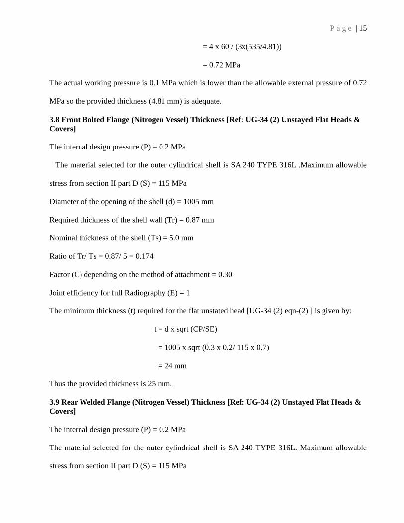
3.8 Front Bolted Flange (Nitrogen Vessel) Thickness [Ref: UG-34 (2) Unstayed Flat Heads &
Covers]
The internal design pressure (P) = 0.2 MPa
The material selected for the outer cylindrical shell is SA 240 TYPE 316L .Maximum allowable
stress from section II part D (S) = 115 MPa
Diameter of the opening of the shell (d) = 1005 mm
Required thickness of the shell wall (Tr) = 0.87 mm
Nominal thickness of the shell (Ts) = 5.0 mm
Ratio of Tr/ Ts = 0.87/ 5 = 0.174
Factor (C) depending on the method of attachment = 0.30
Joint efficiency for full Radiography (E) = 1
The minimum thickness (t) required for the flat unstated head [UG-34 (2) eqn-(2) ] is given by:
t = d x sqrt (CP/SE)
= 1005 x sqrt (0.3 x 0.2/ 115 x 0.7)
= 24 mm
Thus the provided thickness is 25 mm.
3.9 Rear Welded Flange (Nitrogen Vessel) Thickness [Ref: UG-34 (2) Unstayed Flat Heads &
Covers]
The internal design pressure (P) = 0.2 MPa
The material selected for the outer cylindrical shell is SA 240 TYPE 316L. Maximum allowable
stress from section II part D (S) = 115 MPa
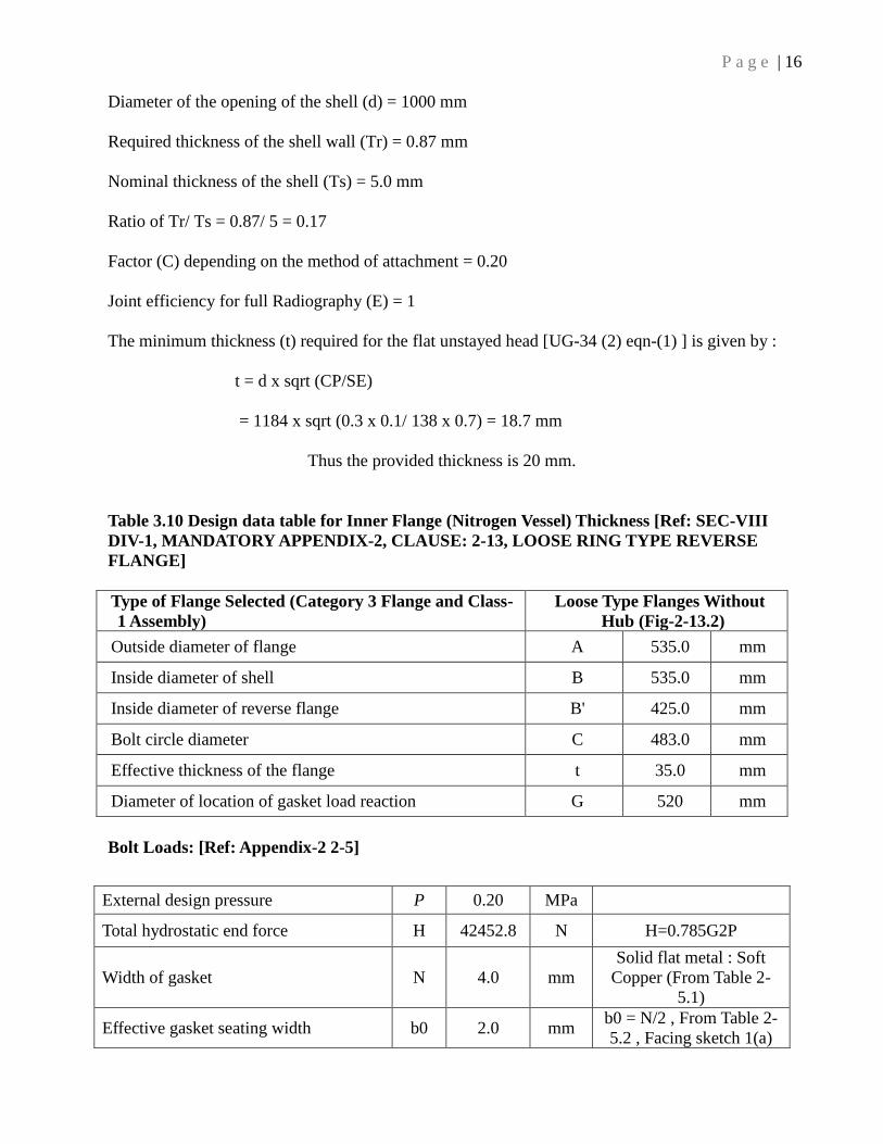
P a g e | 16
Diameter of the opening of the shell (d) = 1000 mm
Required thickness of the shell wall (Tr) = 0.87 mm
Nominal thickness of the shell (Ts) = 5.0 mm
Ratio of Tr/ Ts = 0.87/ 5 = 0.17
Factor (C) depending on the method of attachment = 0.20
Joint efficiency for full Radiography (E) = 1
The minimum thickness (t) required for the flat unstayed head [UG-34 (2) eqn-(1) ] is given by :
t = d x sqrt (CP/SE)
= 1184 x sqrt (0.3 x 0.1/ 138 x 0.7) = 18.7 mm
Thus the provided thickness is 20 mm.
Table 3.10 Design data table for Inner Flange (Nitrogen Vessel) Thickness [Ref: SEC-VIII
DIV-1, MANDATORY APPENDIX-2, CLAUSE: 2-13, LOOSE RING TYPE REVERSE
FLANGE]
Type of Flange Selected (Category 3 Flange and Class-
1 Assembly)
Loose Type Flanges Without
Hub (Fig-2-13.2)
Outside diameter of flange A 535.0 mm
Inside diameter of shell B 535.0 mm
Inside diameter of reverse flange B' 425.0 mm
Bolt circle diameter C 483.0 mm
Effective thickness of the flange t 35.0 mm
Diameter of location of gasket load reaction G 520 mm
Bolt Loads: [Ref: Appendix-2 2-5]
External design pressure P 0.20 MPa
Total hydrostatic end force H 42452.8 N H=0.785G2P
Width of gasket N 4.0 mm
Solid flat metal : Soft
Copper (From Table 2-
5.1)
Effective gasket seating width b0 2.0 mm b0 = N/2 , From Table 2-
5.2 , Facing sketch 1(a)

P a g e | 17
Basic gasket seating width B 2.0 mm b = b0 when b0 < 6 mm
Gasket factor M 4.75 --
For Solid flat metal : Soft
Copper (From Table 2-
5.1)
Gasket or joint contact surface unit
seating load Y 90 MPa
For Solid flat metal : Soft
Copper ( Table 2-5.1)
Total joint contact surface compression
load Hp 6204.6 Hp = 2b x 3.14GmP
Minimum required bolt load for
operating conditions Wm1 48657.4 N Wm1 = H+Hp
Minimum required bolt load for gasket
seating Wm2 293904 N Wm2 = 3.14bGy
Allowable bolt stress at atmospheric
temp. Sa 155.0 MPa
From Section II Part D
Table 3
Allowable bolt stress at design temp. Sb 155.0 MPa From Section II Part D
Table 4
Total crossectional area of bolts at root
of thread, required for operating
conditions
Am1 313.9 mm2 Am1 = Wm1 / Sb
Total crosssectional area of bolts at root
of thread, required for gasket seating Am2 1896.155 mm2 Am2 = Wm2 / Sa
Total required crossectional area of
bolts, taken as greater of Am1 & Am2 Am 1896.2 mm2
Nominal bolt diameter A 12 mm For M12 bolt
Cross-sectional area of bolts using the
root dia of thread = 28 x 72.39 =
2026.92
Ab 2026.92 mm2 Provided = 28 nos.
Flange design bolt load, for operating
conditions W 48657.4 N W = Wm1
Flange design bolt load, for gasket
seating W 304038.3 N W = (Am +Ab)Sa/2
Flange Moments: [Ref: Appendix-2 2-6]
Hydrostatic end force on area inside of
flange HD 44937.3 N HD = 0.785B2P
Gasket load HG 6205 N HG = W-H
Difference between H and HD HT -2484.53 N HT = H-HD
Radial distance from the bolt circle to
the circle on which HD acts hD -26.0 mm
hD = (C-B)/2 From
Table 2-6 Appndx-2
Radial distance from gasket load
reaction to the bolt circle hG -18.5 mm
hG = (C-G)/2 From
Table 2-6 Appndx-2
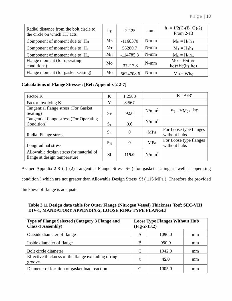
P a g e | 18
Radial distance from the bolt circle to
the circle on which HT acts hT -22.25 mm
hT = 1/2(C-(B+G)/2)
From 2-13
Component of moment due to HD MD -1168370 N-mm MD = HDhD
Component of moment due to HT MT 55280.7 N-mm MT = HThT
Component of moment due to HG MG -114785.8 N-mm MG = HGhG
Flange moment (for operating
conditions) Mo
-37217.8 N-mm
Mo = HG(hD-
hG)+HT(hT-hG)
Flange moment (for gasket seating) Mo -5624708.6 N-mm Mo = WhG
Calculations of Flange Stresses: [Ref: Appendix-2 2-7]
Factor K K 1.2588 K= A/B'
Factor involving K Y 8.567
Tangential flange stress (For Gasket
Seating) ST 92.6 N/mm2 ST = YM0 / t
2B'
Tangential flange stress (For Operating
Condition) ST 0.6 N/mm2
Radial Flange stress SR 0 MPa
For Loose type flanges
without hubs
Longitudinal stress SH 0 MPa
For Loose type flanges
without hubs
Allowable design stress for material of
flange at design temperature Sf 115.0 N/mm2
As per Appndix-2-8 (a) (2) Tangential Flange Stress ST ( for gasket seating as well as operating
condition ) which are not greater than Allowable Design Stress Sf ( 115 MPa ). Therefore the provided
thickness of flange is adequate.
Table 3.11 Design data table for Outer Flange (Nitrogen Vessel) Thickness [Ref: SEC-VIII
DIV-1, MANDATORY APPENDIX-2, LOOSE RING TYPE FLANGE]
Type of Flange Selected (Category 3 Flange and
Class-1 Assembly)
Loose Type Flanges Without Hub
(Fig-2-13.2)
Outside diameter of flange A 1090.0 mm
Inside diameter of flange B 990.0 mm
Bolt circle diameter C 1042.0 mm
Effective thickness of the flange excluding o-ring
groove t 45.0 mm
Diameter of location of gasket load reaction G 1005.0 mm

P a g e | 19
Bolt Loads: [Ref: Appendix-2 2-5]
Internal design pressure P 0.20 N/mm2
Total hydrostatic end force H 158573.9 N H=0.785G2P
Width of gasket N 4.0 mm
Solid flat metal : Soft
Copper (From Table 2-
5.1)
Effective gasket seating width b0 2.0 mm
b0 = N/2 , From Table 2-
5.2 , Facing sketch 1(a)
Basic gasket seating width B 2.0 mm b = b0 when b0 < 6 mm
Gasket factor M 4.75
--
For Solid flat metal : Soft
Copper (From Table 2-
5.1)
Gasket or joint contact surface unit
seating load Y 90 N/mm2
For Solid flat metal : Soft
Copper (From Table 2-
5.1)
Total joint contact surface compression
load
Hp 11991.7
Hp = 2b x 3.14GmP
Minimum required bolt load for
operating conditions Wm1 170565.6 N Wm1 = H+Hp
Minimum required bolt load for gasket
seating Wm2 568026 N Wm2 = 3.14bGy
Allowable bolt stress at atmospheric
temp. Sa
155.0 N/mm2
From Section II Part D
Table 3
Allowable bolt stress at design temp. Sb 155.0 N/mm2 From Section II Part D
Table 4
Total crossectional area of bolts at root
of thread, required for operating
conditions
Am1 1100.4 mm2 Am1 = Wm1 / Sb
Total crossectional area of bolts at root
of thread, required for gasket seating Am2 3664.68 mm2 Am2 = Wm2 / Sa
Total required crossectional area of
bolts, taken as greater of Am1 & Am2 Am 3664.7 mm2
Nominal bolt diameter A 12 mm For M12 bolt
Cross-sectional area of bolts using the
root dia of thread Ab 3764.28 mm2 Provided = 52 nos.
Flange design bolt load, for operating
conditions W 170565.6 N W = Wm1
Flange design bolt load, for gasket seating W 575744.7 N W = (Am +Ab)Sa/2

P a g e | 20
Flange Moments: [Ref: Appendix-2 2-6]
Hydrostatic end force on area inside of
flange HD 153875.7 N HD = 0.785B2P
Gasket load HG 11992 N HG = W-H
Difference between H and HD HT 4698.23 N HT = H-HD
Radial distance from the bolt circle to
the circle on which HD acts hD 26.0 mm
hD = (C-B)/2 From
Table 2-6 Appndx-2
Radial distance from gasket load
reaction to the bolt circle hG 18.5 mm
hG = (C-G)/2 From
Table 2-6 Appndx-2
Radial distance from the bolt circle to
the circle on which HT acts hT 22.3 mm
hT = (hD+hG)/2 From
Table 2-6 Appndx-2
Component of moment due to HD MD 4000768 N-mm MD = HDhD
Component of moment due to HT MT 104535.5 N-mm MT = HThT
Component of moment due to HG MG 221845.7 N-mm MG = HGhG
Flange moment (for operating
conditions) Mo
4327149.4 N-mm
Mo = MD+MT+MG
Flange moment (for gasket seating) Mo 10651277.0 N-mm Mo = W(C-G)/2
Calculations of Flange Stresses: [Ref: Appendix-2 2-7]
Factor K K 1.1010 K= A/B
Factor involving K Y 20.128
Tangential flange stress (For Gasket
Seating) ST 106.9 N/mm2 ST = YM0 / t
2B
Tangential flange stress (For Operating
Condition) ST 43.4 N/mm2
Radial Flange stress SR 0 MPa For Loose type flanges
without hubs
Longitudinal stress SH 0 MPa For Loose type flanges
without hubs
Allowable design stress for material of
flange at design temperature Sf 115.0 N/mm2
As per Appndix-2-8 (a) (2) Tangential Flange Stress ST ( for gasket seating as well as operating
condition ) which are not greater than Allowable Design Stress Sf ( 115 MPa ). Therefore the
provided thickness of flange is adequate
P a g e | 21
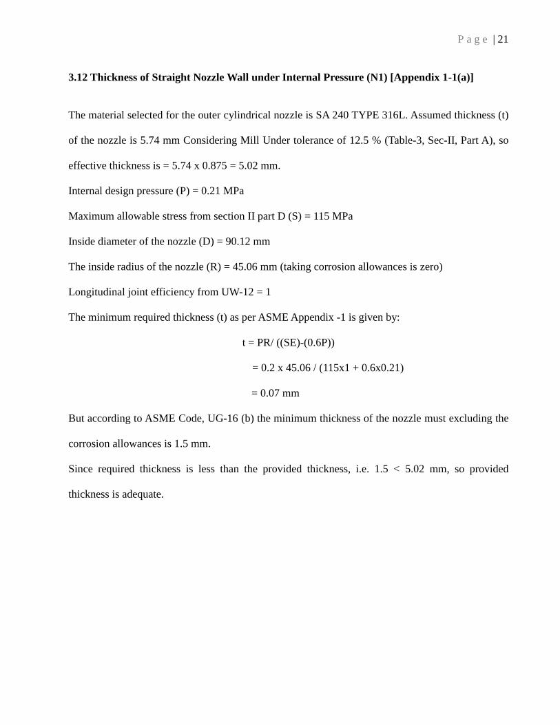
3.12 Thickness of Straight Nozzle Wall under Internal Pressure (N1) [Appendix 1-1(a)]
The material selected for the outer cylindrical nozzle is SA 240 TYPE 316L. Assumed thickness (t)
of the nozzle is 5.74 mm Considering Mill Under tolerance of 12.5 % (Table-3, Sec-II, Part A), so
effective thickness is = 5.74 x 0.875 = 5.02 mm.
Internal design pressure (P) = 0.21 MPa
Maximum allowable stress from section II part D (S) = 115 MPa
Inside diameter of the nozzle (D) = 90.12 mm
The inside radius of the nozzle (R) = 45.06 mm (taking corrosion allowances is zero)
Longitudinal joint efficiency from UW-12 = 1
The minimum required thickness (t) as per ASME Appendix -1 is given by:
t = PR/ ((SE)-(0.6P))
= 0.2 x 45.06 / (115x1 + 0.6x0.21)
= 0.07 mm
But according to ASME Code, UG-16 (b) the minimum thickness of the nozzle must excluding the
corrosion allowances is 1.5 mm.
Since required thickness is less than the provided thickness, i.e. 1.5 < 5.02 mm, so provided
thickness is adequate.
P a g e | 22
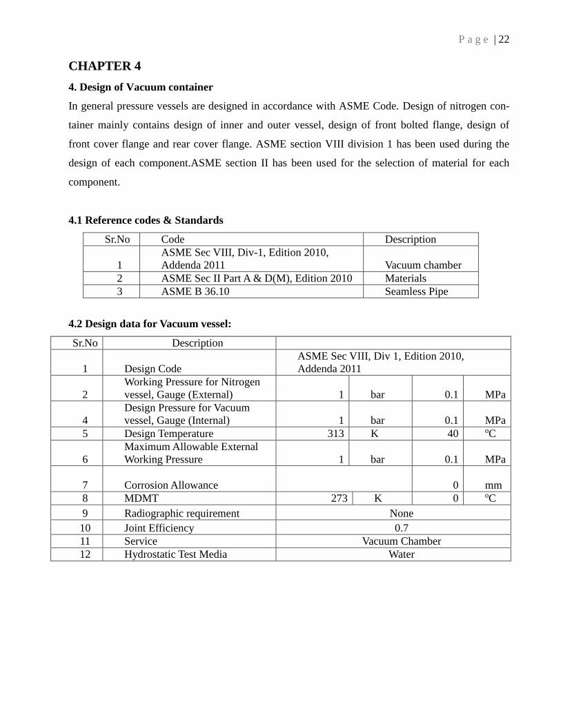
CHAPTER 4
4. Design of Vacuum container
In general pressure vessels are designed in accordance with ASME Code. Design of nitrogen con-
tainer mainly contains design of inner and outer vessel, design of front bolted flange, design of
front cover flange and rear cover flange. ASME section VIII division 1 has been used during the
design of each component.ASME section II has been used for the selection of material for each
component.
4.1 Reference codes & Standards
Sr.No Code Description
1
ASME Sec VIII, Div-1, Edition 2010,
Addenda 2011 Vacuum chamber
2 ASME Sec II Part A & D(M), Edition 2010 Materials
3 ASME B 36.10 Seamless Pipe
4.2 Design data for Vacuum vessel:
Sr.No Description
1 Design Code
ASME Sec VIII, Div 1, Edition 2010,
Addenda 2011
2
Working Pressure for Nitrogen
vessel, Gauge (External) 1 bar 0.1 MPa
4
Design Pressure for Vacuum
vessel, Gauge (Internal) 1 bar 0.1 MPa
5 Design Temperature 313 K 40 oC
6
Maximum Allowable External
Working Pressure 1 bar 0.1 MPa
7 Corrosion Allowance
0 mm
8 MDMT 273 K 0 oC
9 Radiographic requirement None
10 Joint Efficiency 0.7
11 Service Vacuum Chamber
12 Hydrostatic Test Media Water
P a g e | 23
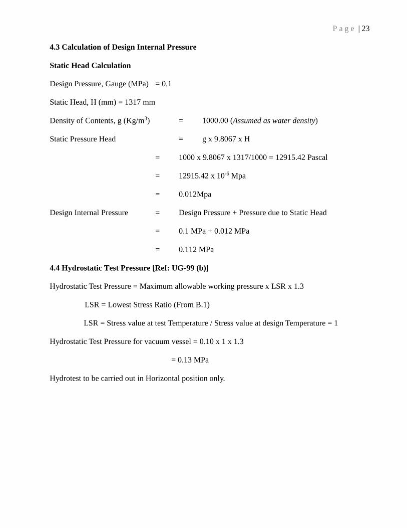
4.3 Calculation of Design Internal Pressure
Static Head Calculation
Design Pressure, Gauge (MPa) = 0.1
Static Head, H (mm) = 1317 mm
Density of Contents, g (Kg/m3) = 1000.00 (Assumed as water density)
Static Pressure Head = g x 9.8067 x H
= 1000 x 9.8067 x 1317/1000 = 12915.42 Pascal
= 12915.42 x 10-6 Mpa
= 0.012Mpa
Design Internal Pressure = Design Pressure + Pressure due to Static Head
= 0.1 MPa + 0.012 MPa
= 0.112 MPa
4.4 Hydrostatic Test Pressure [Ref: UG-99 (b)]
Hydrostatic Test Pressure = Maximum allowable working pressure x LSR x 1.3
LSR = Lowest Stress Ratio (From B.1)
LSR = Stress value at test Temperature / Stress value at design Temperature = 1
Hydrostatic Test Pressure for vacuum vessel = 0.10 x 1 x 1.3
= 0.13 MPa
Hydrotest to be carried out in Horizontal position only.
P a g e | 24
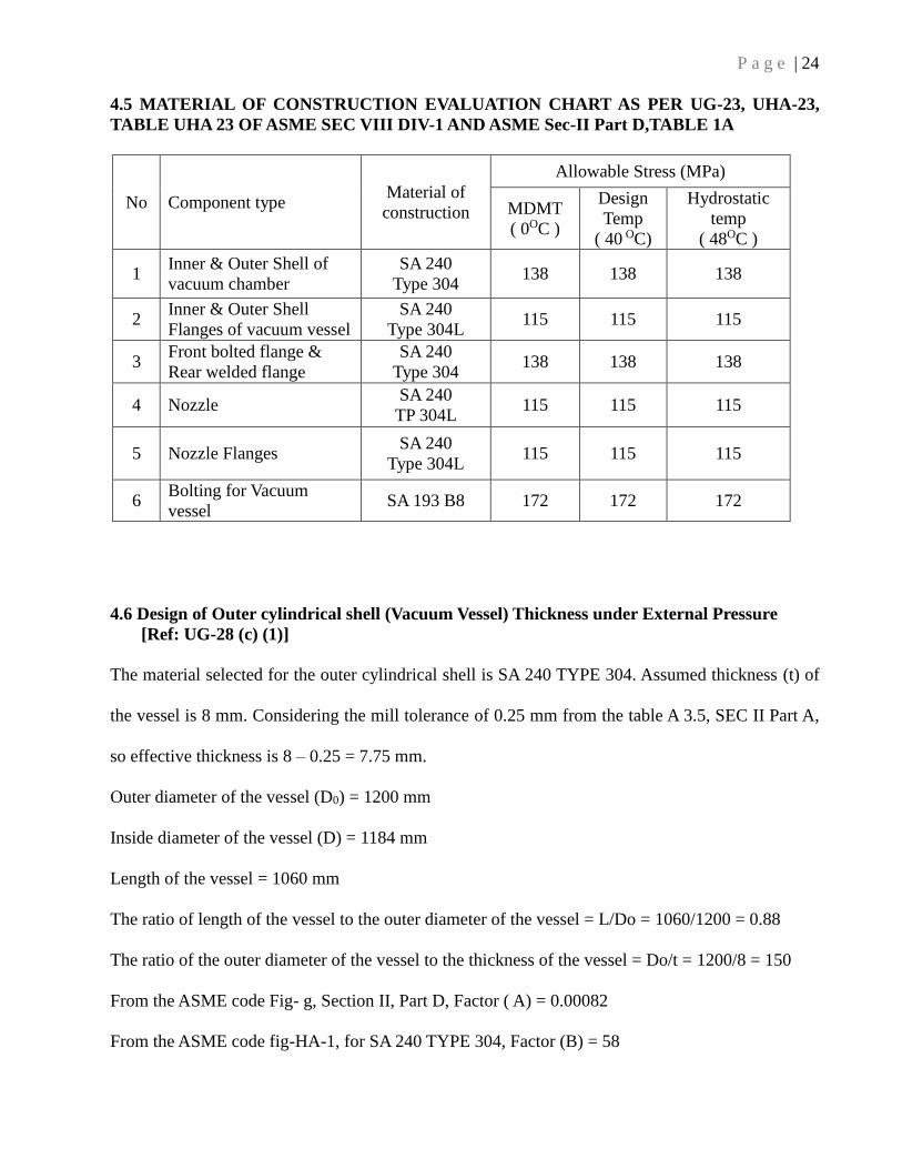
4.5 MATERIAL OF CONSTRUCTION EVALUATION CHART AS PER UG-23, UHA-23,
TABLE UHA 23 OF ASME SEC VIII DIV-1 AND ASME Sec-II Part D,TABLE 1A
No Component type Material of
construction
Allowable Stress (MPa)
MDMT
( 0OC )
Design
Temp
( 40 OC)
Hydrostatic
temp
( 48OC )
1 Inner & Outer Shell of
vacuum chamber
SA 240
Type 304 138 138 138
2 Inner & Outer Shell
Flanges of vacuum vessel
SA 240
Type 304L 115 115 115
3 Front bolted flange &
Rear welded flange
SA 240
Type 304 138 138 138
4 Nozzle SA 240
TP 304L 115 115 115
5 Nozzle Flanges SA 240
Type 304L 115 115 115
6 Bolting for Vacuum
vessel SA 193 B8 172 172 172
4.6 Design of Outer cylindrical shell (Vacuum Vessel) Thickness under External Pressure
[Ref: UG-28 (c) (1)]
The material selected for the outer cylindrical shell is SA 240 TYPE 304. Assumed thickness (t) of
the vessel is 8 mm. Considering the mill tolerance of 0.25 mm from the table A 3.5, SEC II Part A,
so effective thickness is 8 – 0.25 = 7.75 mm.
Outer diameter of the vessel (D0) = 1200 mm
Inside diameter of the vessel (D) = 1184 mm
Length of the vessel = 1060 mm
The ratio of length of the vessel to the outer diameter of the vessel = L/Do = 1060/1200 = 0.88
The ratio of the outer diameter of the vessel to the thickness of the vessel = Do/t = 1200/8 = 150
From the ASME code Fig- g, Section II, Part D, Factor ( A) = 0.00082
From the ASME code fig-HA-1, for SA 240 TYPE 304, Factor (B) = 58
P a g e | 25
The allowable external pressure working pressure (Pa) from the code is given by:
Pa = 4B / (3*(Do/t))
= 4 x 58 / (3 x (1200/7.75))
= 0.50 MPa
The actual working pressure is 0.1 MPa which is lower than the allowable external pressure of 0.50
MPa so the provided thickness (7.75 mm) is adequate.
4.7 Design of Inner cylindrical shell (Vacuum Vessel) Thickness under Internal
Pressure [Ref: UG-27]
The material selected for the outer cylindrical shell is SA 240 TYPE 304. Assumed thickness (t) of
the vessel is 8 mm. Considering the mill tolerance of 0.25 mm from the UG 16 (c), table A 3.5, SEC
II Part A, so effective thickness is 8 – 0.25 = 7.75 mm.
Internal design pressure (P) = 0.1 MPa
Maximum allowable stress from section II part D (S) = 138 MPa
The outer diameter of the vessel (D0) = 316 mm
Inside diameter of the vessel (D) = 300 mm
The inside radius of the vessel (R) = 150 mm (taking corrosion allowances is zero )
Longitudinal joint efficiency from UW-12 = 0.7
The minimum required thickness (t) as per ASME Appindix -1 is given by :
t = PR/((SE)-(0.6P))
= 0.1x150 / (138x0.7 - 0.6x0.1)
= 0.15 mm
But according to ASME Code, UG-16 (b) the minimum thickness of the shell must be 1/16 inch
excluding the corrosion allowances i.e 1.5 mm.
Since required thickness is less than the provided thickness, i.e. 1.5 < 7.75 mm, So provided
P a g e | 26
thickness is adequate.
4.8 Design of Outer Cylindrical Shell (Vacuum Vessel) Thickness under Internal
Pressure [Ref: UG-27]
The material selected for the outer cylindrical shell is SA 240 TYPE 304. Assumed thickness (t) of
the vessel is 8 mm. Considering the mill tolerance of 0.25 mm from the UG 16 (c), table A 3.5, SEC
II Part A, so effective thickness is 8 – 0.25 = 7.75 mm.
Internal design pressure (P) = 0.1 MPa
Maximum allowable stress from section II part D (S) = 138 MPa
The outer diameter of the vessel (D0) = 1200 mm
The outer radius of the vessel (Ro) = 600 mm
Inside diameter of the vessel (D) = 1184 mm
The inside radius of the vessel (R) = 592 mm (taking corrosion allowances is zero )
Longitudinal joint efficiency from UW-12 = 0.7
The minimum required thickness (t) as per ASME Appendix -1 is given by:
t = PR/((SE)-(0.6P))
= 0.1x592 / (138x0.7 - 0.6x0.1)
= 0.61 mm
But according to ASME Code, UG-16 (b) the minimum thickness of the shell must be 1/16 inch
excluding the corrosion allowances i.e 1.5 mm.
Since required thickness is less than the provided thickness, i.e. 1.5 < 7.75 mm, So provided
thickness is adequate
P a g e | 27
4.9 Design of Front Bolted Flange (Vacuum Vessel) Thickness [Ref: UG-34 (2) Unstayed Flat
Heads & Covers]
The internal design pressure (P) = 0.1 MPa
Maximum allowable stress from section II part D (S) = 138 MPa
Diameter of the opening of the shell (d) = 1184 mm
Required thickness of the shell wall (Tr) = 0.61 mm
Nominal thickness of the shell (Ts) = 8.0 mm
Ratio of Tr/ Ts = 0.61/ 8 = 0.08
Factor (C) depending on the method of attachment = 0.30
Joint efficiency for full Radiography (E) = 0.7
The minimum thickness (t) required for the flat unstayed head [UG-34 (2) eqn-(2) ] is given by :
t = d x sqrt (CP/SE)
= 1184 x sqrt( 0.3 x 0.1/ 138 x 0.7)
= 21 mm
Thus the provided thickness is 22 mm.
4.10 Design of Rear Welded Flange (Vacuum Vessel) Thickness [Ref: UG-34 (2) Unstayed Flat
Heads & Covers]
The internal design pressure (P) = 0.1 MPa
Maximum allowable stress from section II part D (S) = 138 MPa
Diameter of the opening of the shell (d) = 1184 mm
Required thickness of the shell wall (Tr) = 0.61 mm
Nominal thickness of the shell (Ts) = 8.0 mm
Ratio of Tr/ Ts = 0.61/ 8 = 0.08
Factor (C) depending on the method of attachment = 0.20
Joint efficiency for full Radiography (E) = 0.7
P a g e | 28
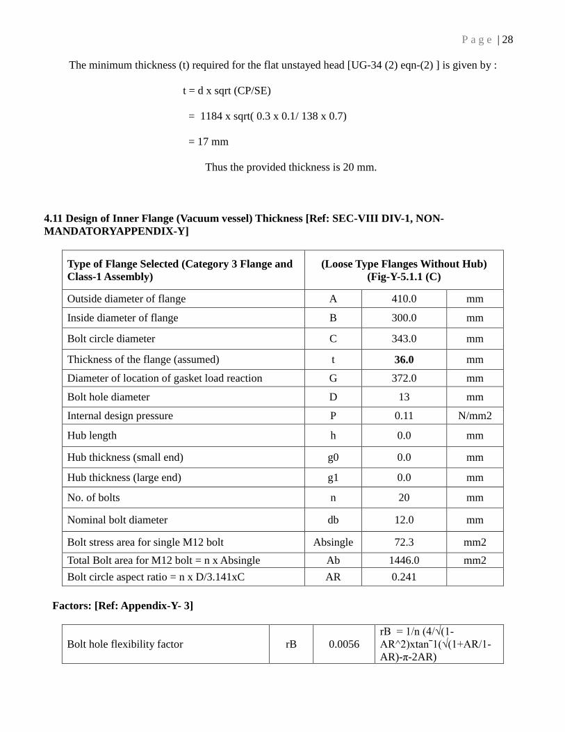
The minimum thickness (t) required for the flat unstayed head [UG-34 (2) eqn-(2) ] is given by :
t = d x sqrt (CP/SE)
= 1184 x sqrt( 0.3 x 0.1/ 138 x 0.7)
= 17 mm
Thus the provided thickness is 20 mm.
4.11 Design of Inner Flange (Vacuum vessel) Thickness [Ref: SEC-VIII DIV-1, NON-
MANDATORYAPPENDIX-Y]
Type of Flange Selected (Category 3 Flange and
Class-1 Assembly)
(Loose Type Flanges Without Hub)
(Fig-Y-5.1.1 (C)
Outside diameter of flange A 410.0 mm
Inside diameter of flange B 300.0 mm
Bolt circle diameter C 343.0 mm
Thickness of the flange (assumed) t 36.0 mm
Diameter of location of gasket load reaction G 372.0 mm
Bolt hole diameter D 13 mm
Internal design pressure P 0.11 N/mm2
Hub length h 0.0 mm
Hub thickness (small end) g0 0.0 mm
Hub thickness (large end) g1 0.0 mm
No. of bolts n 20 mm
Nominal bolt diameter db 12.0 mm
Bolt stress area for single M12 bolt Absingle 72.3 mm2
Total Bolt area for M12 bolt = n x Absingle Ab 1446.0 mm2
Bolt circle aspect ratio = n x D/3.141xC AR 0.241
Factors: [Ref: Appendix-Y- 3]
Bolt hole flexibility factor rB 0.0056
rB = 1/n (4/√(1-
AR^2)xtanˉ1(√(1+AR/1-
AR)-π-2AR)

P a g e | 29
Integral flange factor ho 0.0 h0 = SQRT (Bxg0)
Factor K K 1.3667 K = A/B
B1 = B for loose type flange B1 300
Shape Factor β 1.0717 β = (C+B1)/2xB1
Shape Factor a 1.255 a= (A+C)/2xB1
Bolt Loads and Flange Moments: [Ref: Appendix-Y-4 ]
Total hydrostatic end force H 11949.5 N H=0.785G2P
Gasket load due to seating pressure HG 0 For self sealing O-ring
Total joint contact surface
compression load Hp 0 Hp = 2b x 3.14GmP
Hydrostatic end force on area inside
of flange HD 7771.5 N HD = 0.785B2P
Difference between H and HD HT 4178.0 N HT = H-HD
Radial distance from the bolt circle
to point of intersection of hub and
back of flange
R 21.5 mm hD = (C-B)/2 - g1
From Appndx-2
Radial distance from the bolt circle
to the circle on which HD acts hD 21.5 mm
hD = (C-B)/2 From
Table 2-6 Appndx-2
Radial distance from gasket load
reaction to the bolt circle hG -14.5 mm
hG = (C-G)/2 From
Table 2-6 Appndx-2
Radial distance from the bolt circle
to the circle on which HT acts hT 3.5 mm
hT = (hD+hG)/2 From
Table 2-6 Appndx-2
Radial distance from the bolt circle
to the outer edge of flange or spacer
whichever is less
Hc
33.5 mm
hc = (A-C)/2
F' 0.0 For category 3 class 1
assembly
Js 0.24 1/B1[(2xhxD)/β +
hc/a] + 3.141xrB
Jp 0.17 1/B1[(hxD)/β + hc/a]
+ 3.141xrB
Component of moment due to HD MD 167087.25 N-mm MD = HDhD
Component of moment due to HT MT 14622.85 N-mm MT = HThT
Component of moment due to HG MG 0.0 N-mm MG = HGhG
Moment dur to HD, HT, HG MP 181710.10 N-mm MP = MD + MT + MG

P a g e | 30
Flange moment due to Flange-Hub
Interaction MS 0.0
Slope of Flange at Inside Diameter
Times E EθB 1.2
Contact force between flanges at hC Hc 5424.2 N HC = (MP + MS) / Hc
Bolt load at operating condition Wm1 17373.6 N Wm1 = H + HC + HG
Operating Bolt stress Σb 12 N/mm2 σb = WM1/Ab
spacer thickness Ts 0.0 mm
Calculated strain length of bolt L 78 mm l = 2t + ts + (1/2db)
Design Pre stress in bolts Si 11.84 N/mm2
Calculations of Flange Stresses: [Ref: Appendix-Y- 6.1]
Radial flange stress at bolt circle SR 0.00 N/mm2
Longitudinal hub stress SH 0.00 N/mm2
Tangential flange stress at inside diameter ST 0.14 N/mm2 ST = t x EθB / B1
Allowable bolt stress at atmospheric temp. Sa 130 N/mm2 For B8 Grade
SA 193 Table 3
Allowable bolt stress at design temp. Sb 130 N/mm2
Allowable design stress for material of flange
at design temperature Sf 115 N/mm2
As per Appndix-Y-7 Tangential Flange Stress ST not greater than Allowable Design Stress SF (115
MPa) and Operating bolt stress σb is not greater than Allowable bolt stress Sb.
Therefore the provided thickness of flange is adequate.
4.12 Design of Outer Flange (Vacuum vessel) Thickness [Ref: SEC-VIII DIV-1,
NON- MANDATORYAPPENDIX-Y]
Type of Flange Selected (Category 3 Flange and
Class-1 Assembly)
(Loose Type Flanges Without Hub)
(Fig-Y-5.1.1 (C)
Outside diameter of flange A 1184.0 mm
Inside diameter of flange B 1110.0 mm
Bolt circle diameter C 1158.0 mm
Thickness of the flange (assumed) t 36.0 mm
Diameter of location of gasket load reaction G 1129.0 mm
Bolt hole diameter D 13 mm
Internal design pressure P 0.11 N/mm2
Hub length h 0.0 mm
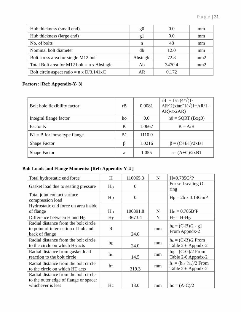
P a g e | 31
Hub thickness (small end) g0 0.0 mm
Hub thickness (large end) g1 0.0 mm
No. of bolts n 48 mm
Nominal bolt diameter db 12.0 mm
Bolt stress area for single M12 bolt Absingle 72.3 mm2
Total Bolt area for M12 bolt = n x Absingle Ab 3470.4 mm2
Bolt circle aspect ratio = n x D/3.141xC AR 0.172
Factors: [Ref: Appendix-Y- 3]
Bolt hole flexibility factor rB 0.0081
rB = 1/n (4/√(1-
AR^2)xtanˉ1(√(1+AR/1-
AR)-π-2AR)
Integral flange factor ho 0.0 h0 = SQRT (Bxg0)
Factor K K 1.0667 K = A/B
B1 = B for loose type flange B1 1110.0
Shape Factor β 1.0216 β = (C+B1)/2xB1
Shape Factor a 1.055 a= (A+C)/2xB1
Bolt Loads and Flange Moments: [Ref: Appendix-Y-4 ]
Total hydrostatic end force H 110065.3 N H=0.785G2P
Gasket load due to seating pressure HG 0
For self sealing O-
ring
Total joint contact surface
compression load Hp 0 Hp = 2b x 3.14GmP
Hydrostatic end force on area inside
of flange HD 106391.8 N HD = 0.785B2P
Difference between H and HD HT 3673.4 N HT = H-HD
Radial distance from the bolt circle
to point of intersection of hub and
back of flange
R
24.0
mm hD = (C-B)/2 - g1
From Appndx-2
Radial distance from the bolt circle
to the circle on which HD acts hD
24.0 mm
hD = (C-B)/2 From
Table 2-6 Appndx-2
Radial distance from gasket load
reaction to the bolt circle hG
14.5 mm
hG = (C-G)/2 From
Table 2-6 Appndx-2
Radial distance from the bolt circle
to the circle on which HT acts hT
319.3 mm
hT = (hD+hG)/2 From
Table 2-6 Appndx-2
Radial distance from the bolt circle
to the outer edge of flange or spacer
whichever is less Hc 13.0 mm hc = (A-C)/2

P a g e | 32
F' 0.0
For category 3 class 1
assembly
Js 0.08
1/B1[(2xhxD)/β +
hc/a] + 3.141xrB
Jp 0.06
1/B1[(hxD)/β + hc/a]
+ 3.141xrB
Component of moment due to HD MD 2553404.04 N-mm MD = HDhD
Component of moment due to HT MT 70713.25 N-mm MT = HThT
Component of moment due to HG MG 0.0 N-mm MG = HGhG
Moment dur to HD, HT, HG
MP
2624117.29 N-mm MP = MD + MT + MG
Flange moment due to Flange-Hub
Interaction MS
0.0
Slope of Flange at Inside Diameter
Times E EθB
5.6
Contact force between flanges at hC Hc 201855.2 N HC = (MP + MS) / Hc
Bolt load at operating condition Wm1 311920.4 N Wm1 = H + HC + HG
Operating Bolt stress Σb 89.9 N/mm2 σb = WM1/Ab
spacer thickness Ts 0.0 mm
Calculated strain length of bolt L 78.0 mm l = 2t + ts + (1/2db)
Design Pre stress in bolts Si 89.76 N/mm2
Calculations of Flange Stresses: [Ref: Appendix-Y- 6.1]
Radial flange stress at bolt circle SR 0.00 N/mm2
Longitudinal hub stress SH 0.00 N/mm2
Tangential flange stress at inside
diameter ST 0.18
N/mm2 ST = t x EθB / B1
Allowable bolt stress at atmospheric
temp. Sa 130
N/mm2
For B8 Grade SA
193 Table 3
Allowable bolt stress at design temp. Sb 130 N/mm2
Allowable design stress for material of
flange at design temperature Sf 115 N/mm2
As per Appndix-Y-7 Tangential Flange Stress ST not greater than Allowable Design Stress Sf ( 115
MPa ) and Operating bolt stress σb is not greater than Allowable bolt stress Sb.
Therefore the provided thickness of flange is adequate.
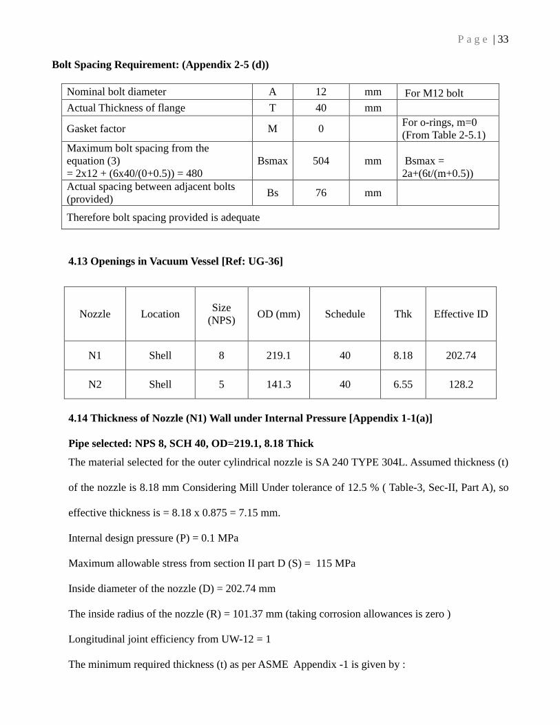
P a g e | 33
Bolt Spacing Requirement: (Appendix 2-5 (d))
Nominal bolt diameter A 12 mm For M12 bolt
Actual Thickness of flange T 40 mm
Gasket factor M 0 For o-rings, m=0
(From Table 2-5.1)
Maximum bolt spacing from the
equation (3)
= 2x12 + (6x40/(0+0.5)) = 480
Bsmax 504 mm Bsmax =
2a+(6t/(m+0.5))
Actual spacing between adjacent bolts
(provided) Bs 76 mm
Therefore bolt spacing provided is adequate
4.13 Openings in Vacuum Vessel [Ref: UG-36]
4.14 Thickness of Nozzle (N1) Wall under Internal Pressure [Appendix 1-1(a)]
Pipe selected: NPS 8, SCH 40, OD=219.1, 8.18 Thick
The material selected for the outer cylindrical nozzle is SA 240 TYPE 304L. Assumed thickness (t)
of the nozzle is 8.18 mm Considering Mill Under tolerance of 12.5 % ( Table-3, Sec-II, Part A), so
effective thickness is = 8.18 x 0.875 = 7.15 mm.
Internal design pressure (P) = 0.1 MPa
Maximum allowable stress from section II part D (S) = 115 MPa
Inside diameter of the nozzle (D) = 202.74 mm
The inside radius of the nozzle (R) = 101.37 mm (taking corrosion allowances is zero )
Longitudinal joint efficiency from UW-12 = 1
The minimum required thickness (t) as per ASME Appendix -1 is given by :
Nozzle Location Size
(NPS) OD (mm) Schedule Thk Effective ID
N1 Shell 8 219.1 40 8.18 202.74
N2 Shell 5 141.3 40 6.55 128.2

P a g e | 34
t = PR/((SE)-(0.4P))
= 0.1x101.37/ (115x0.7 + 0.4x0.1)
= 0.126 mm
But according to ASME Code, UG-16 (b) the minimum thickness of the nozzle must exclude the
corrosion allowances is 1.5 mm.
Since the required thickness is less than the provided thickness, i.e. 1.5 < 7.15 mm, So provided
thickness is adequate.
4.15 Thickness of Nozzle (N2) Wall under Internal Pressure [Appendix 1-1(a)]
Pipe selected: NPS 5 SCH 40, OD=141.3, 6.55 Thick
The material selected for the outer cylindrical nozzle is SA 240 TYPE 304L. Assumed thickness (t)
of the nozzle is 6.55 mm Considering Mill Under tolerance of 12.5 % (Table-3, Sec-II, Part A), so
effective thickness is = 6.55 x 0.875 = 5.73 mm.
Internal design pressure (P) = 0.1 MPa
Maximum allowable stress from section II part D (S) = 115 MPa
Inside diameter of the nozzle (D) = 128.2 mm
The inside radius of the nozzle (R) = 114.1 mm (taking corrosion allowances is zero)
Longitudinal joint efficiency from UW-12 = 1
The minimum required thickness (t) as per ASME Appendix -1 is given by :
t = PR/((SE)-(0.4P))
= 0.1 x 64.1/ (115x0.7 + 0.4x0.1)
= 0.07 mm
But according to ASME Code, UG-16 (b) the minimum thickness of the nozzle must excludi the
corrosion allowances is 1.5 mm.
Since required thickness is less than the provided thickness, i.e. 1.5 < 5.73 mm, So provided
P a g e | 35
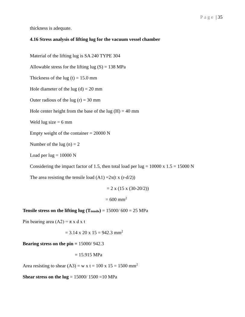
thickness is adequate.
4.16 Stress analysis of lifting lug for the vacuum vessel chamber
Material of the lifting lug is SA 240 TYPE 304
Allowable stress for the lifting lug (S) = 138 MPa
Thickness of the lug (t) = 15.0 mm
Hole diameter of the lug (d) = 20 mm
Outer radious of the lug (r) = 30 mm
Hole center height from the base of the lug (H) = 40 mm
Weld lug size = 6 mm
Empty weight of the container = 20000 N
Number of the lug (n) = 2
Load per lug = 10000 N
Considering the impact factor of 1.5, then total load per lug = 10000 x 1.5 = 15000 N
The area resisting the tensile load (A1) =2x(t x (r-d/2))
= 2 x (15 x (30-20/2))
= 600 mm2
Tensile stress on the lifting lug (Ttensile) = 15000/ 600 = 25 MPa
Pin bearing area (A2) = π x d x t
= 3.14 x 20 x 15 = 942.3 mm2
Bearing stress on the pin = 15000/ 942.3
= 15.915 MPa
Area resisting to shear (A3) = w x t = 100 x 15 = 1500 mm2
Shear stress on the lug = 15000/ 1500 =10 MPa

P a g e | 36
CHAPTER 5
5.0 Thermal Design of Nitrogen Storage Container
Proper thermal designing in cryogenic systems is the most challenging design for cryogenic appa-
ratus like liquid nitrogen storage containers, which directly impacts on the performance during its
operation. The thermal design should be such that heat loss will be minimized as much as possible
and it should be in the acceptable range. The heat transfer basically occurs in three ways;
Conduction - heat transfer through solids
Convection - heat transfer through liquids and gases
Radiation – heat transfer through space
Heat transfer through conduction can be more precisely calculated, but in the case heat transfer
through convection and radiation a reasonable approximate estimate can be done.
In liquid Helium or Nitrogen storage container, it needs to have the least amount of heat load com-
ing in to that storage container (at 4.2 K or 77K). The maximum contribution of heat load that can
be transferred in to the storage container is due to natural convection from the atmospheric air
which is at 300 K, hence to reduce the heat load due to natural convection we need to evacuate the
space between vacuum chamber and the nitrogen storage chamber. The space can be evacuated us-
ing roughing pump and the turbo pump to create a vacuum in the range of 10−5 mbar. The number
of gas molecules reduces at vacuum condition which increases the mean free path of the gas mole-
cules, approximately at 10^-4 mbar , mean free path is about 100 cm which is more than the dis-
tance between the surfaces which leads to reduce heat load to few milliwatts at vacuum of 10−5
mbar. Multilayer insulation, which consists of highly reflective aluminum sheets are intended to re-
duce radiation heat transfer. Insulator like G10 material is used as the separators between the nitro-
gen chamber and the vacuum chamber for reducing the conduction heat load.
In nitrogen container vessel, total heat loss is mainly due to the conduction, radiation only.
P a g e | 37
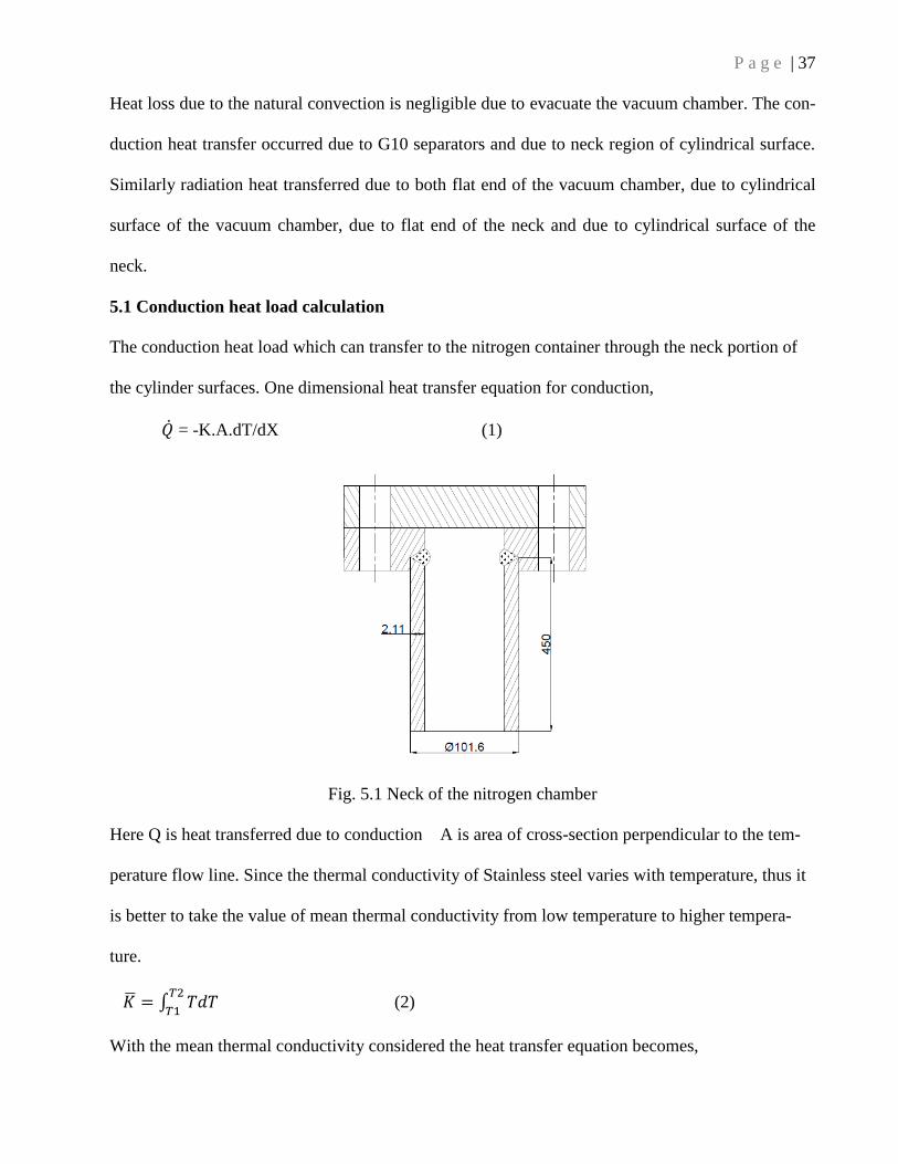
Heat loss due to the natural convection is negligible due to evacuate the vacuum chamber. The con-
duction heat transfer occurred due to G10 separators and due to neck region of cylindrical surface.
Similarly radiation heat transferred due to both flat end of the vacuum chamber, due to cylindrical
surface of the vacuum chamber, due to flat end of the neck and due to cylindrical surface of the
neck.
5.1 Conduction heat load calculation
The conduction heat load which can transfer to the nitrogen container through the neck portion of
the cylinder surfaces. One dimensional heat transfer equation for conduction,
�̇� = -K.A.dT/dX (1)
Fig. 5.1 Neck of the nitrogen chamber
Here Q is heat transferred due to conduction A is area of cross-section perpendicular to the tem-
perature flow line. Since the thermal conductivity of Stainless steel varies with temperature, thus it
is better to take the value of mean thermal conductivity from low temperature to higher tempera-
ture.
�̅� = ∫ 𝑇𝑑𝑇𝑇2
𝑇1 (2)
With the mean thermal conductivity considered the heat transfer equation becomes,
P a g e | 38
�̇� = �̅� x 𝐴
𝐿 (3)
Conduction heat load on the nitrogen chamber due to following reasons:
Due to G10 separators
Due to neck region of cylindrical surface
5.1.1 Conduction heat load due to G10 supports:
Outer diameter of G10 separator = 40 mm = 0.04 m
Inner Diameter of G10 separator = 25 mm = 0.025 m
A = Area exposed for conduction = 𝜋
4x(0.042 − 0.0252)= 0.000765 m2
dx = Thickness of the G10 separator = 110 mm = 0.011 m
K = thermal conductivity of G10 = 0.5 W.𝑚−1𝑘−1
Atmospheric temperature T1 = 300K
Liquid nitrogen temp. T2 = 77 K
Total number of separator = 15
The conduction heat transfer due to G10 support Qc1 = K.A.𝑑𝑇
𝑑𝑥
Qc1 = 0.5 x 0.000765 x 15 x (300− 77)
0.110
Qc1 = 11.6 watt
5.1.2 Conduction heat load due to neck region of cylindrical surface:
We have a SS304 neck with ID= 97.38 mm and OD = 101.6 mm and length 450 mm. one end is at
300K and the other at 80K for the maximum possible heat load that can be transferred to the liquid
nitrogen.
P a g e | 39
For SS304 mean thermal conductivity from 300 to 80 K = 2711W/m (from Experimental Tempera-
ture for Low-temperature measurements by Jack.W.Ekin)
Cross-sectional area of the pipe A = 𝜋
4x(0. 1012 − 0.097382)= 0.563*10−3 m2
Therefore conduction heat transferred through the neck Qc2 = �̅�.𝐴
𝐿
Qc2 = 2711x0.563∗10−3
0.45
Qc2 = 3.39 W
Total heat loss due to conduction Qc = Qc1 + Qc2
= 14.99 watt
5.2 Radiation heat load calculation
Radiation heat transfer takes place in space in the form of electromagnetic waves.
When a hot body radiating energy to the surrounding cooler body, then the net heat transferred ac-
cording to Stefan-Boltzmann Law occurred due to radiation is given below.
q = ε σ (Th4 - Tc
4) A
where,
q = heat transfer per unit time due to radiation
Th = hot body temperature
Tc = cold surroundings temperature
A = area of the object exposed to radiation (m2)
σ = 5.6703 10-8 (W/m2K4) - The Stefan-Boltzmann Constant
T = absolute temperature Kelvin (K)

P a g e | 40
5.2.1 Radiation heat load due to flat end of vacuum chamber:
D = Diameter of the flat end exposed to radiation = 1100 mm = 1.1 m
Atmospheric temperature T1 = 300K
Liquid nitrogen temp. T2 = 77 K
A = Area exposed to radiation = 𝜋
4x1.12 = 0.95 m2
Emissivity of multilayer insulation aluminum foil = 0.05
No of layers of insulation = 46
Radiation heat transfer QR1 = σ x A x ϵ x (𝑇14 - 𝑇24), where 𝜎 = 5.67x 10⁻⁸ W 𝑚−2 𝐾−4
QR1 = 5.67x 10−8 x 0.95 x 0.05
46 x (3004 -774)
= 0.47 Watt
5.2.2 Radiation heat load due to cylindrical surface of vacuum chamber:
D = Outer diameter of the vacuum chamber = 0.1016 m
L = Length of the neck = 1 m
Outer surface area exposed to radiation (A) = π x D x L
A = 3.45 𝑚2
Atmospheric temperature T1 = 300K
Liquid nitrogen temp. T2 = 77 K
Emissivity of multilayer insulation aluminum foil = 0.05
No of layers of insulation = 46
Radiation heat transfer QR2 = σ x A x ϵ x (𝑇14 - 𝑇24), where 𝜎 = 5.67x 10⁻⁸ W 𝑚−2 𝐾−4
QR2 = 5.67x 10−8 x 3.45 x 0.05
46 x (3004 -774)
QR2 = 0.95 watt
5.2.3 Radiation heat load due to flat end of neck portion:
D = Diameter of the flat end exposed to radiation = 101.6mm = 0.1016m

P a g e | 41
Atmospheric temperature T1 = 3000K
Liquid nitrogen temp. T2 = 77 K
Area A = 𝜋
4x0.1012 = 0.0081 m2
Radiation heat transfer QR3 = σ x A x ϵ x (𝑇14 - 𝑇24), where 𝜎 = 5.67x 10⁻⁸ W 𝑚−2 𝐾−4
QR3 = 5.67x 10−8 x 0.0081 x 0.02 x (3004 -774)
= 0.074 Watt
5.2.4 Radiation heat load due to cylindrical surface of neck portion:
D = Outer diameter of the neck = 0.1016 m
L = Length of the neck = 0.45 m
Outer surface area exposed to radiation (A) = π x D x L
A = 0.143 𝑚2
Atmospheric temperature T1 = 300K
Liquid nitrogen temp. T2 = 77 K
Emissivity of multilayer insulation aluminum foil = 0.05
No of layers of insulation = 30
Radiation heat transfer QR4 = σ x A x ϵ x (𝑇14 - 𝑇24), where 𝜎 = 5.67x 10⁻⁸ W 𝑚−2 𝐾−4
QR4 = 5.67x 10−8 x 0.143 x 0.05
30 x (3004 -774)
QR4 = 0.1 watt
Total heat loss due to radiation QR = QR1 + QR2 + QR3 + QR4
= 0.47 + 0.95 +0.074 + 0.1
= 1.59 watt
Total Heat load Q = Qc + QR
= 14.99 + 1.59
= 16.58 watts

P a g e | 42
Total heat load Q = �̇�.hf
Where hf is latent heat of vaporization and �̇� is mass flow rate
Latent heat of vaporization of liquid nitrogen = 199 J/s
1 liter of liquid nitrogen = 0.8 kg
I kg of liquid nitrogen = 1.25 liters
Mass flow rate (�̇�) = 16.58/199 = 0.08 g/s =0.28 kg/hr = 0.35 liters/ hr
Thus the rate of evaporation of liquid nitrogen is about 0.35 liters per hour.

P a g e | 43
CHAPTER 6
6.1 CAD and Finite Element Method
After finalizing dimensions like the thickness of individual components from ASME design code,
2D concept layout drawing (as sown in fig. 6.1) has been developed in AUTOCAD software and
consequently we developed the 3D model (as shown in fig. 6.2) in PRO-E software which was ex-
ported to ANSYS for Finite Element Analysis purposes. Solid meshing was done on the full as-
sembly and proper contact parameters were defined between the individual components. Separate
material properties were assigned for different types of materials. Internal pressure has been applied
to the inner nitrogen chamber and external pressure applied to the outer vacuum chamber.
Fig.6.1: 2D Layout concept drawing
Vacuum chamber
G10 Separator
Multi-layer insulation
Lifting lug
Support structure
P a g e | 44
In layout drawing twenty numbers of G10 separators are used in between the nitrogen chamber and the
vacuum chamber for the reduce conduction heat transfer. Some multilayer insulation having high reflec-
tivity and low thermal conductivity are used to reduce radiation heat transfer. Multilayer insulation
consists of the multiple layer of thin aluminum sheets of thickness 5 – 12 nm on Mylar film. Rear end
covers are connected with the both nitrogen vessel and vacuum vessel through the welding process,
whereas front end covers are attached with the vessels through the bolt joints. Front flange rings are also
connected with vessel through weld joints.
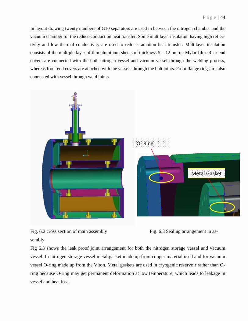
Fig. 6.2 cross section of main assembly Fig. 6.3 Sealing arrangement in as-
sembly
Fig 6.3 shows the leak proof joint arrangement for both the nitrogen storage vessel and vacuum
vessel. In nitrogen storage vessel metal gasket made up from copper material used and for vacuum
vessel O-ring made up from the Viton. Metal gaskets are used in cryogenic reservoir rather than O-
ring because O-ring may get permanent deformation at low temperature, which leads to leakage in
vessel and heat loss.
O- Ring
Metal Gasket

P a g e | 45
6.1: Finite Element Analysis Plots
Finite element analysis was performed by ANSYS 11.0 software; first we imported the 3D model
from the Pro-E software. All the fasteners, Sharpe edges and small surfaces are removed from the
main model for achieving a fine mesh model. Proper material properties like young modulus and
Poisson’s ratios for different types of materials have been assigned separately. Proper contact pa-
rameters are also assigned for different joints. Solid92 element is used for model meshing. 1 bar ex-
ternal pressure has applied on the vacuum chamber and 2 bar internal pressure applied on the nitro-
gen vessel and the portion surfaces which are resting over the support assembly are fixed as shown
in fig 6.4. it is observed that the maximum 102 Mpa stress (fig. 6.6) developed on the vessel assem-
bly which is well below the yield stress of the specified material. Total displacement (Fig. 6.5) on
the vessel during loading is 0.14 mm which is very small.
Fig. 6.4 Loading and Boundary condition Fig. 6.5 Total displacement plot
Fig 6.6 Von mises stress plot
P a g e | 46
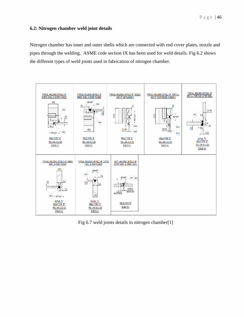
6.2: Nitrogen chamber weld joint details
Nitrogen chamber has inner and outer shells which are connected with end cover plates, nozzle and
pipes through the welding. ASME code section IX has been used for weld details. Fig 6.2 shows
the different types of weld joints used in fabrication of nitrogen chamber.
Fig 6.7 weld joints details in nitrogen chamber[1]
P a g e | 47
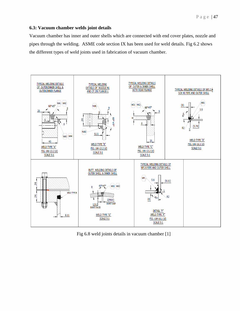
6.3: Vacuum chamber welds joint details
Vacuum chamber has inner and outer shells which are connected with end cover plates, nozzle and
pipes through the welding. ASME code section IX has been used for weld details. Fig 6.2 shows
the different types of weld joints used in fabrication of vacuum chamber.
Fig 6.8 weld joints details in vacuum chamber [1]

P a g e | 48
CHAPTER 7
7. Fabrication and Assembly of Vessel
All the components are manufactured as per the part drawing. Dimensional tolerances and surface finish
are the critical parameter during the assembly of the components. During assembly front cover end is
connected with vessel through the bolt joints. Nozzles are connected with the vessel through the TIG
welding and CF flanges are connected with the nozzle through the TIG welding. The following fig. 7.1
shows the liquid nitrogen vessel during assembly.
Fig. 7.1 Assembly of LN2 Storage Container
P a g e | 49
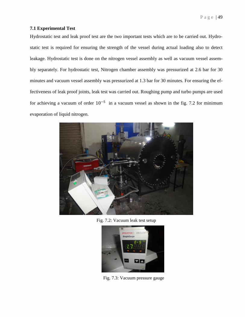
7.1 Experimental Test
Hydrostatic test and leak proof test are the two important tests which are to be carried out. Hydro-
static test is required for ensuring the strength of the vessel during actual loading also to detect
leakage. Hydrostatic test is done on the nitrogen vessel assembly as well as vacuum vessel assem-
bly separately. For hydrostatic test, Nitrogen chamber assembly was pressurized at 2.6 bar for 30
minutes and vacuum vessel assembly was pressurized at 1.3 bar for 30 minutes. For ensuring the ef-
fectiveness of leak proof joints, leak test was carried out. Roughing pump and turbo pumps are used
for achieving a vacuum of order 10−5 in a vacuum vessel as shown in the fig. 7.2 for minimum
evaporation of liquid nitrogen.
Fig. 7.2: Vacuum leak test setup
Fig. 7.3: Vacuum pressure gauge
P a g e | 50
CHAPTER 8
8.1 Discussion and Conclusions
The liquid nitrogen storage vessel has been designed as per ASME Boiler and Pressure Vessel
Code. ASME section II used for material selection, section V used for nondestructive testing like
weld defect detection, section VIII division 1 used for design of components and section IX used
for welding and brazing qualification.
Finite Element Analysis of the assembly was carried out by ANSYS workbench and found that
maximum Vonmises stress was 102 MPa which is well below the yield limit of the specified mate-
rial, thus the design is safe.
Total heat load transferred to the nitrogen chamber is minimized by implementing multilayer insu-
lation for the reduction of radiation heat transfer, G10 insulator separator for reduction in conduc-
tion heat transfer and a evacuated chamber of order 10−5 mbar for the reduction in convection heat
transfer. The total heat load on the nitrogen chamber is 16.58 watts, which shows the effective
thermal design of the nitrogen storage container.
Hydrostatic test was carried out through the water medium on both nitrogen chamber assembly and
the vacuum vessel assembly separately for ensuring the strength against the specified load and it is
found that both the assembly passed the required criteria.
To find any defect in welding and material, cold shock test was carryout five times on the assembly
and it is observed that there was no crack or defect found on the material as well as in welding.
For minimum evaporation of the liquid nitrogen, a higher order (10−5 ) of vacuum was created by
the vacuum chamber over the nitrogen chamber, metal gasket (Cu) used in nitrogen chamber and
O-ring (NBR) used in vacuum chamber was used for leak proof joints.
P a g e | 51
REFERENCES
[1] ASME Boiler and Pressure Vessel Code, Section VIII, Division 1, 2011a Addenda, American
Society of Mechanical Engineers.
[2] Denis R. Moss” Pressure Vessel Design and Development manual, third edition, Elsevier
publisher inc.
[3] Hollinger GL, Hechmer JL. Phase 1 report: three dimensional stress criteria. New York, NY:
PVRC; 1991. Grant 89-16 and 90-13.
[4] WRC 429, Hechmer JL, Hollinger GL. 3D stress criteria e guidelines for application. Welding
Research Council, Inc; 1998. Bulletin WRC 429.
[5] S.M.A Khan, Stress distributions in a horizontal pressure vessel and the saddle supports,
International Journal of Pressure Vessels and Piping 87 (2010) 239- 244.
[6] H. Mayer, H.L Stark, S. Ambrose Review of fatigue design procedure for pressure vessel,
Internationa Journal Pressure Vessel and Piping 77(2000) 775-781
[7] S.V Dubal, S.Y.Gajjal, V.G Patil Review on Stresses in Cylindrical Pressure Vessel and its
Design as per ASME Code, International Journal of Engineering Trends and Technology, Volume11
May 2014
[8] Petrovic, A., 2001, Stress Analysis of the cylindrical vessel with load applied to the free end of
the nozzle, international Journal of Pressure vessels and Piping 78, 485- 493.
[9] M.Jeyakumar, T.Christopher, Influence of residual stresses on failure pressure of cylindrical
pressure vessels, Chinese Journal of Aeronautics, (2013),26(6): 1415–1421
[10] A.Th. Diamantoudis*, Th. Kermanidis, Design by analysis versus design by formula of high
strength steel pressure vessels: a comparative study, International Journal of Pressure Vessels and
Piping 82 (2005) 43–50