
DESIGN AND DEVELOPMENT OF FIXTURE WITH CANTILEVER ...
5
DESIGN AND DEVELOPMENT OF FIXTURE WITH CANTILEVER BEAM FOR INTER MEDIATE GEAR BOX K.PRABHAKAR 1* , Dr .M. ASHOK KUMAR 2 ,E.V.SUBBAREDDY 3 ,S.KASIMVALI 4 . 1* Department of Mechanical Engineering, GATES Institute of Technology, Gooty,Anantapur,A.P. 2 Department of Mechanical Engineering, GATES Institute of Technology, Gooty,Anantapur,A.P. 3 Department of Mechanical Engineering, Kottam college of Engineering,chinnatekur,Kurnool,A.P. 4 Department of Mechanical Engineering, GATES Institute of Technology,Gooty,Anatapur,A.P. Abstract The steel industry involves various production methods and processes for steel manufacturing and end products. This in turn is done with the help of heavy duty industrial machines and equipment. Heavy-duty and powerful industrial machines including Converters, Continuous casting machines, crane slew drives, conveyors and winches are used in the steel industry. Various components including powerful gearboxes are used in these machines for ensuring a smooth power transmission. Our team successfully reduced repair time by crashing the dismantling time of both halves of gear box casing and in turn reduced man-hours consumption. This was achieved by design and manufacturing a fixture which can separate both halves of gearbox casing within minutes using a 100 The hydraulic jack. Keywords—fixture, hydraulic jack, intermediate gear box,development. INTRODUCTION: , Industrial gearboxes used in the steel industry provide high torque with high reduction ratios. They are available in a range of sizes, specifications and configurations to suit the different needs of the industry. Intermediate gear box of concast stand is one of the gear boxes which drive the roller of stand. As the service conditions at continuous casting department not favorable to equipment like gear boxes, the maintenance of these gear boxes is toughest task. The damaged gear boxes along with concast stands are being repaired at Central Machine Shop. Our project work involves study the existing procedure of repair of gear box. Analyze the existing process and suggest improved method of repairing the gear box slashing both time and man-hours consumption. . The life of strand 1&4 TK stands are more compared to strand 2&3 due to simplicity in its arrangement and direct connection to co-axial reduction gear boxes, but in strand 2&3 TK stands the bottom rollers are driven by Intermediate Gear Box through spline mechanism. The IGB is only a power transfer unit; it does not either reduce or increase speed. The IGB consists of input gear, intermediate gear and an output gear. The output gear is mounted on a hollow output shaft, which is having internal splines. These splines are matched with the bottom roller external splines. METHODOLOGY Specification: Reduction Ratio : 1:1 No. of Stages : 2 Power transmitted : 30 KW Input : Z1=50; m=10 Intermediate : Z2=70; m=10 Output : Z3 = 50; m=10 RPM : 1 No. of gear boxes installed : 48 Type of casing : Split K Prabhakar et al, Int.J.Computer Technology & Applications,Vol 4 (6),892-896 IJCTA | Nov-Dec 2013 Available [email protected] 892 ISSN:2229-6093
Transcript of DESIGN AND DEVELOPMENT OF FIXTURE WITH CANTILEVER ...
DESIGN AND DEVELOPMENT OF FIXTURE WITH CANTILEVER BEAM FOR INTER MEDIATE GEAR BOX
K.PRABHAKAR1*, Dr .M. ASHOK KUMAR2,E.V.SUBBAREDDY3,S.KASIMVALI4.
1*Department of Mechanical Engineering, GATES Institute of Technology, Gooty,Anantapur,A.P.
2Department of Mechanical Engineering, GATES Institute of Technology, Gooty,Anantapur,A.P. 3 Department of Mechanical Engineering, Kottam college of Engineering,chinnatekur,Kurnool,A.P.
4Department of Mechanical Engineering, GATES Institute of Technology,Gooty,Anatapur,A.P.
Abstract The steel industry involves various production methods and processes for steel manufacturing and end products. This in turn is done with the help of heavy duty industrial machines and equipment. Heavy-duty and powerful industrial machines including Converters, Continuous casting machines, crane slew drives, conveyors and winches are used in the steel industry. Various components including powerful gearboxes are used in these machines for ensuring a smooth power transmission. Our team successfully reduced repair time by crashing the dismantling time of both halves of gear box casing and in turn reduced man-hours consumption. This was achieved by design and manufacturing a fixture which can separate both halves of gearbox casing within
minutes using a 100 The hydraulic jack. Keywords—fixture, hydraulic jack, intermediate gear
box,development.
INTRODUCTION: , Industrial gearboxes used in the steel industry provide
high torque with high reduction ratios. They are
available in a range of sizes, specifications and
configurations to suit the different needs of the industry.
Intermediate gear box of concast stand is one of the
gear boxes which drive the roller of stand. As the service
conditions at continuous casting department not
favorable to equipment like gear boxes, the
maintenance of these gear boxes is toughest task. The
damaged gear boxes along with concast stands are
being repaired at Central Machine Shop. Our project
work involves study the existing procedure of repair of
gear box. Analyze the existing process and suggest
improved method of repairing the gear box slashing
both time and man-hours consumption.
.
The life of strand 1&4 TK stands are more compared to strand
2&3 due to simplicity in its arrangement and direct connection
to co-axial reduction gear boxes, but in strand 2&3 TK stands
the bottom rollers are driven by Intermediate Gear Box
through spline mechanism.
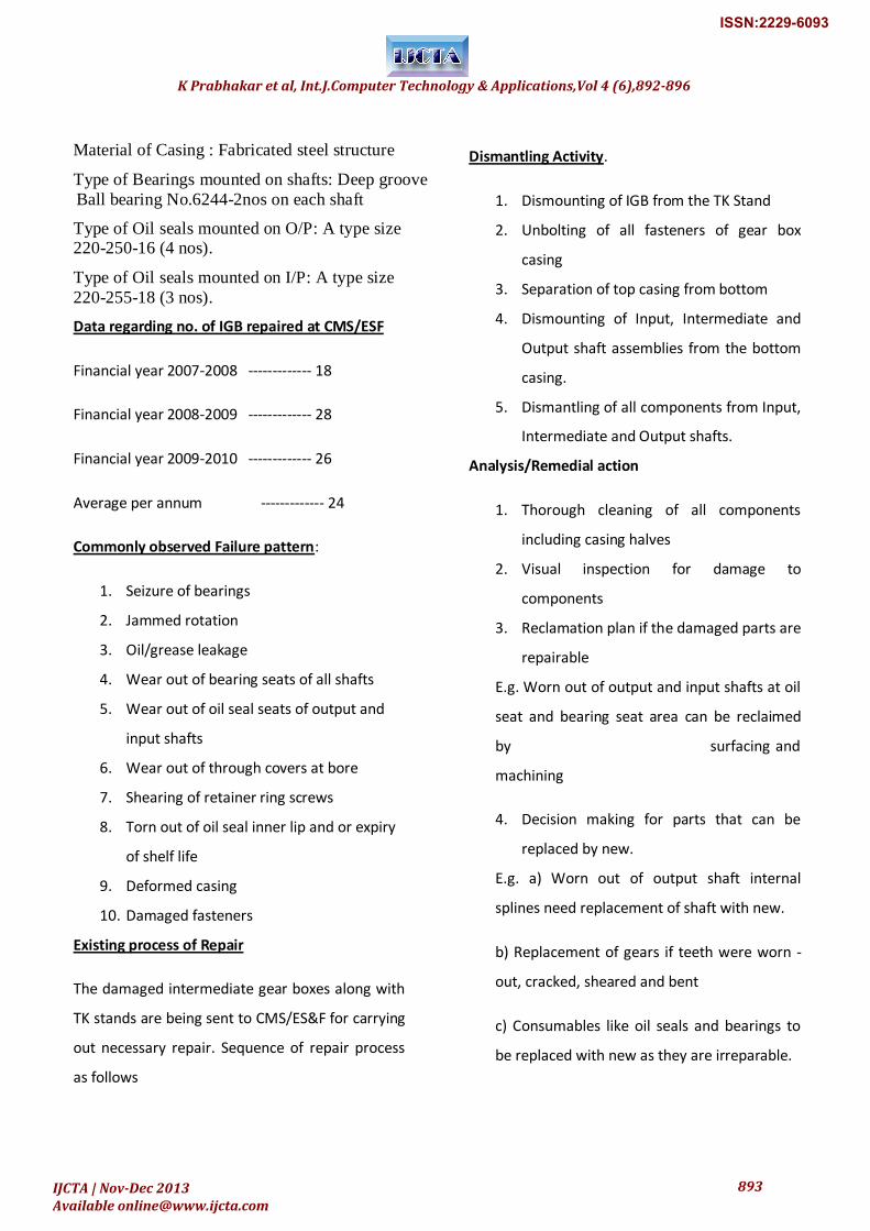
The IGB is only a power transfer unit; it does not
either reduce or increase speed. The IGB consists of input gear,
intermediate gear and an output gear. The output gear is
mounted on a hollow output shaft, which is having
internal splines. These splines are matched with the bottom
roller external splines.
METHODOLOGY
Specification:
Reduction Ratio : 1:1
No. of Stages : 2
Power transmitted : 30 KW
Input : Z1=50; m=10
Intermediate : Z2=70; m=10
Output : Z3 = 50; m=10
RPM : 1
No. of gear boxes installed : 48
Type of casing : Split
K Prabhakar et al, Int.J.Computer Technology & Applications,Vol 4 (6),892-896
IJCTA | Nov-Dec 2013 Available [email protected]
892
ISSN:2229-6093
Material of Casing : Fabricated steel structure
Type of Bearings mounted on shafts: Deep groove
Ball bearing No.6244-2nos on each shaft
Type of Oil seals mounted on O/P: A type size 220-250-16 (4 nos).
Type of Oil seals mounted on I/P: A type size
220-255-18 (3 nos).
Data regarding no. of IGB repaired at CMS/ESF
Financial year 2007-2008 ------------- 18
Financial year 2008-2009 ------------- 28
Financial year 2009-2010 ------------- 26
Average per annum ------------- 24
Commonly observed Failure pattern:
1. Seizure of bearings
2. Jammed rotation
3. Oil/grease leakage
4. Wear out of bearing seats of all shafts
5. Wear out of oil seal seats of output and
input shafts
6. Wear out of through covers at bore
7. Shearing of retainer ring screws
8. Torn out of oil seal inner lip and or expiry
of shelf life
9. Deformed casing
10. Damaged fasteners
Existing process of Repair
The damaged intermediate gear boxes along with
TK stands are being sent to CMS/ES&F for carrying
out necessary repair. Sequence of repair process
as follows
Dismantling Activity.
1. Dismounting of IGB from the TK Stand
2. Unbolting of all fasteners of gear box
casing
3. Separation of top casing from bottom
4. Dismounting of Input, Intermediate and
Output shaft assemblies from the bottom
casing.
5. Dismantling of all components from Input,
Intermediate and Output shafts.
Analysis/Remedial action
1. Thorough cleaning of all components
including casing halves
2. Visual inspection for damage to
components
3. Reclamation plan if the damaged parts are
repairable
E.g. Worn out of output and input shafts at oil
seat and bearing seat area can be reclaimed
by surfacing and
machining
4. Decision making for parts that can be
replaced by new.
E.g. a) Worn out of output shaft internal
splines need replacement of shaft with new.
b) Replacement of gears if teeth were worn -
out, cracked, sheared and bent
c) Consumables like oil seals and bearings to
be replaced with new as they are irreparable.
K Prabhakar et al, Int.J.Computer Technology & Applications,Vol 4 (6),892-896
IJCTA | Nov-Dec 2013 Available [email protected]
893
ISSN:2229-6093
Assembling
1. Assembling of input, output and
intermediate shafts, replacing damaged
components with new or repaired parts
2. Mounting of all three internals on bottom
casing of gear box.
3. Positioning of blind and through covers
along with rubber cords to arrest lubricant
leakage.
4. Mounting of top casing on bottom casing.
Clamping both halves of casing by bolting.
5. Checking proper mating of both casing
parts
6. Inspection of gear box for free rotation of
shafts and lubricant leak
7. Deliver the gear box for fixing it to TK
Stand.
It is clear from the data that maximum load
applied is 63T.As there is only 100T jack above 63T
in CMS; we selected this jack for the unit.
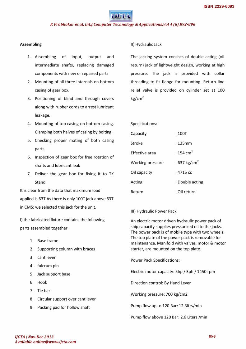
I) the fabricated fixture contains the following
parts assembled together
1. Base frame
2. Supporting column with braces
3. cantilever
4. fulcrum pin
5. Jack support base
6. Hook
7. Tie bar
8. Circular support over cantilever
9. Packing pad for hollow shaft
II) Hydraulic Jack
The jacking system consists of double acting (oil
return) jack of lightweight design, working at high
pressure. The jack is provided with collar
threading to fit flange for mounting. Return line
relief valve is provided on cylinder set at 100
kg/cm2
Specifications:
Capacity : 100T
Stroke : 125mm
Effective area : 154 cm2
Working pressure : 637 kg/cm2
Oil capacity : 4715 cc
Acting : Double acting
Return : Oil return
III) Hydraulic Power Pack
An electric motor driven hydraulic power pack of ship capacity supplies pressurized oil to the jacks. The power pack is of mobile type with two wheels. The top plate of the power pack is removable for maintenance. Manifold with valves, motor & motor starter, are mounted on the top plate.
Power Pack Specifications:
Electric motor capacity: 5hp / 3ph / 1450 rpm
Direction control: By Hand Lever
Working pressure: 700 kg/cm2
Pump flow up to 120 Bar: 12.3ltrs/min
Pump flow above 120 Bar: 2.6 Liters /min
K Prabhakar et al, Int.J.Computer Technology & Applications,Vol 4 (6),892-896
IJCTA | Nov-Dec 2013 Available [email protected]
894
ISSN:2229-6093
Test pressure: 700 kg/cm2
Tank capacity: 50 liters
Benefits of modified System:
Modified Vs Existing dismantling process
Drive the wedges between parting surfaces of gear box by heavy hammering.
Place, clamp and assemble the cantilever after placing the gear box on base frame of fixture. Jack the lever with hydraulic jack to separate both halves of the casing.
Comparison between two methods:
A. Figure.
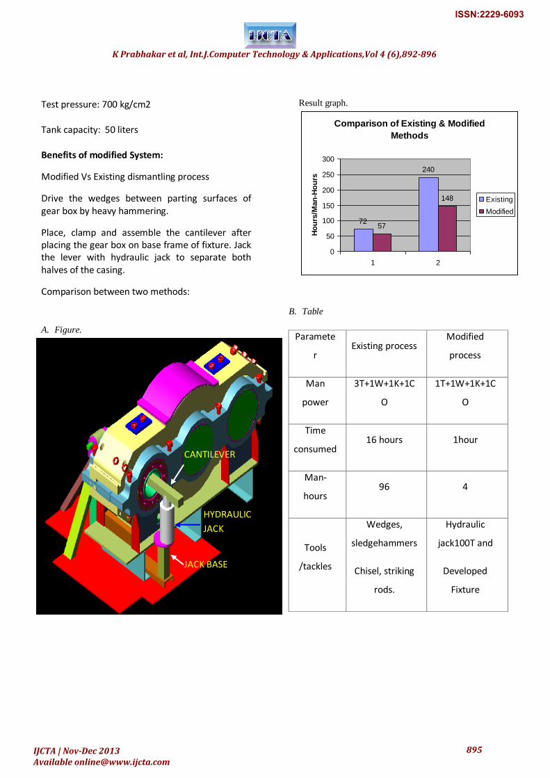
Result graph.
Comparison of Existing & Modified
Methods
72
240
57
148
0
50
100
150
200
250
300
1 2
Ho
urs
/Man
-Ho
urs
Existing
Modified
B. Table
Paramete
r Existing process
Modified
process
Man
power
3T+1W+1K+1C
O
1T+1W+1K+1C
O
Time
consumed 16 hours 1hour
Man-
hours 96 4
Tools
/tackles
Wedges,
sledgehammers
Chisel, striking
rods.
Hydraulic
jack100T and
Developed
Fixture
HYDRAULIC
JACK
CANTILEVER
JACK BASE
K Prabhakar et al, Int.J.Computer Technology & Applications,Vol 4 (6),892-896
IJCTA | Nov-Dec 2013 Available [email protected]
895
ISSN:2229-6093
CONCLUSION
This paper dealt with repair activity of
Intermediate gear box and Development of
Fixture with cantilever beam using hydraulic
jack in the process of repair. The remedial
action for preventing injury to workmen as
well as damage to Gear box casing and other
components in is addressed with modified
procedure for dismantling Gear box Casing
through specialized Fixture in combination
with hydraulic jack.
C. References :
[1] Design data Hand book by K.Balaveerareddy.
[2] Design of machine elements by shigley, TMGH.
[3] www.fixtures.cm
[4]www.hydraulicjacks.com
[5]Machine design by S.Md.jallaluddin, anuradha
Publications.
[6] Jigs and Fixture Design Edward G.Hoffman.
[7] Hand book of Gear Design Gitin M.Maitra TMGH.
2nd
edition.
[8] Jigs and Fixtures – P.H. Joshi, TMGH.
K Prabhakar et al, Int.J.Computer Technology & Applications,Vol 4 (6),892-896
IJCTA | Nov-Dec 2013 Available [email protected]
896
ISSN:2229-6093