DESIGN AND DEVELOPMENT OF COLIFORM …eprints.uthm.edu.my/8800/1/NURULAZIRAH_BINTI_MD_SALIH.pdf ·...
48
DESIGN AND DEVELOPMENT OF COLIFORM BACTERIA DETECTION SYSTEM INTEGRATED WITH MICROFLUIDIC AND OPTICAL ABSORBANCE MEASUREMENT DEVICE NURULAZIRAH BINTI MD SALIH UNIVERSITI TUN HUSSEIN ONN MALAYSIA
Transcript of DESIGN AND DEVELOPMENT OF COLIFORM …eprints.uthm.edu.my/8800/1/NURULAZIRAH_BINTI_MD_SALIH.pdf ·...

DESIGN AND DEVELOPMENT OF COLIFORM
BACTERIA DETECTION SYSTEM INTEGRATED
WITH MICROFLUIDIC AND OPTICAL
ABSORBANCE MEASUREMENT DEVICE
NURULAZIRAH BINTI MD SALIH
UNIVERSITI TUN HUSSEIN ONN MALAYSIA

UNIVERSITI TUN HUSSEIN ONN MALAYSIA
STATUS CONFIRMATION FOR MASTER’S THESIS
DESIGN AND DEVELOPMENT OF COLIFORM BACTERIA DETECTION
SYSTEM INTEGRATED WITH MICROFLUIDIC AND OPTICAL
ABSORBANCE MEASUREMENT DEVICE
ACADEMIC SESSION : 2015/2016
I, NURULAZIRAH BINTI MD SALIH, agree to allow this Master’s Thesis to be kept at the
Library under the following terms:
1. This Master’s Thesis is the property of Universiti Tun Hussein Onn Malaysia.
2. The library has the right to make copies for educational purposes only.
3. The library is allowed to make copies of this report for educational exchange between
higher educational institutions.
4. ** Please Mark (√)
CONFIDENTIAL
(Contains information of high security or of great
importance to Malaysia as STIPULATED under the
OFFICIAL SECRET ACT 1972)
RESTRICTED
(Contains restricted information as determined by
the Organization/institution where research was
conducted)
FREE ACCESS
_________________________
Approved by,
__________________________
(WRITER’S SIGNATURE)
(SUPERVISOR’S SIGNATURE)
Permanent Address :
NO 6, KAMPUNG PARIT LAPIS
KADIR, 83200 SENGGARANG,
BATU PAHAT, JOHOR
Date: 29 FEBRUARY 2016
Date: 29 FEBRUARY 2016
NOTE:
** If this Master’s Thesis is classified as CONFIDENTIAL or RESTRICTED,
Please attach the letter from the relevant authority/organization stating
reasons and duration for such classifications.
This thesis has been examined on 8th December 2015
and is sufficient in fulfilling the scope and quality for the purpose of awarding
Degree of Master.
Chairperson:
PROF. MADYA IR. DR. BABUL SALAM BIN KSM KADER IBRAHIM
Faculty of Electrical and Electronic Engineering
Universiti Tun Hussein Onn Malaysia
Examiners:
PROF. MADYA DR. CHAN KAH YOONG
Faculty of Engineering
Multimedia University (MMU)
PROF. MADYA SITI HAWA BINTI RUSLAN
Faculty of Electrical and Electronic Engineering
Universiti Tun Hussein Onn Malaysia

DESIGN AND DEVELOPMENT OF COLIFORM BACTERIA DETECTION
SYSTEM INTEGRATED WITH MICROFLUIDIC AND OPTICAL
ABSORBANCE MEASUREMENT DEVICE
NURULAZIRAH BINTI MD SALIH
A thesis is submitted in
fulfillment of the requirement for the award of the
Degree of Master of Electrical Engineering
Faculty of Electrical and Electronic Engineering
Universiti Tun Hussein Onn Malaysia
FEBRUARY 2016

ii
I hereby declare that the work in this thesis is my own except for quotations and
summaries which have been duly acknowledged.
Student : ……………………………………………………
NURULAZIRAH BINTI MD SALIH
Date : …………………………………………………….
Supervisor : …………………………………………………….
DR. MOHD ZAINIZAN BIN SAHDAN
Co-supervisor : …………………………………………………….
DR. SOON CHIN FHONG
DECLARATION
29 FEBRUARY 2016

iii
For my parents
For my brothers and sisters
For my teachers
For my friends
DEDICATION

iv
ACKNOWLEDGEMENT
Alhamdulillah, I am grateful to Allah S.W.T. for the good health and wellbeing that
were necessary to complete this thesis.
I wish to express my sincere thanks to my supervisor, Dr Mohd Zainizan bin
Sahdan and my co-supervisor, Dr Soon Chin Fhong for their help and support
throughout this project. I am extremely thankful and indebted to them for the
valuable guidance and encouragement extended to me.
I take this opportunity to express my gratitude to the Microelectronics and
Nanotechnolgy - Shamsuddin Research Centre (MiNT-SRC, UTHM), Molecular
Biology Laboratory (UTHM), Institute of Nano Electronic Engineering (INEE,
UNIMAP), Low Dimensional Materials Research Centre (LDMRC, UM) and the
Faculty of Electrical and Electronic Engineering (FKEE, UTHM) for providing me
all the necessary facilities for the completion of this research. I would like to thank
all the members and staffs for their help and contribution.
Uncountable thanks to my beloved family and friends for the unceasing
encouragement, support and attention. I also place on record, my sense of gratitude
to one and all, who directly or indirectly, have lent their hand in my project.

v
ABSTRACT
The detection of coliform bacteria which contain the disease-causing microorganism
is a useful indication for water contamination. This primary indication is important
for diagnosis of infectious disease, as well as for countermeasure to potential
biological threats. Currently, the emerging of technology in molecular biology
research and industry is in demand for portable and miniaturized system. This project
involved with design and development of microfluidic and optical absorbance
measurement device for coliform bacteria detection system. Suitable microfluidic
design was simulated in the COMSOL Multiphysics software. The microfluidic
device was designed for coliform bacteria sample using optical detection approach.
The microfluidic device was fabricated with glass and polydimethylsiloxane (PDMS)
material using photolithography, replica moulding (soft lithography), and oxygen
plasma bonding techniques. Then, the optical absorbance measurement device for
coliform bacteria detection was developed based on the optical absorbance theory.
The device was constructed using 470 nm blue light emitting diode (LED), photo
detector, ARDUINO microcontroller, liquid crystal display (LCD), and mechanical
elements. This project had successfully developed a prototype which integrates the
PDMS-glass based microfluidic and optical absorbance measurement device. The
absorbance measurement from the prototype and colony number of the coliform
bacteria samples were collected and analyzed. The collected data was used for the
prototype programme. The final analysis had indicated that the developed prototype
was able to detect the coliform bacteria in suspension at the lowest detection of
13,400 CFU/ml.

vi
ABSTRAK
Pengesanan bakteria coliform yang mengandungi mikroorganisma penyebab
penyakit adalah satu petunjuk berguna untuk pencemaran air. Petunjuk utama ini
adalah penting bagi diagnosis kepada penyakit berjangkit, serta penting bagi
tindakan terhadap potensi ancaman biologi. Pada masa kini, perkembangan teknologi
dalam penyelidikan biologi molekular dan industri mempunyai permintaan untuk
sistem yang mudah alih dan kecil. Projek ini melibatkan fabrikasi menggunakan
integrasi alat cecair mikro dan alat pengukur serapan optik untuk sistem pengesanan
bakteria coliform. Reka bentuk alat cecair mikro yang sesuai telah disimulasi
menggunakan perisian COMSOL Multiphysics. Peranti ini direka bentuk untuk
sampel bakteria coliform dan pendekatan pengesanan optik. Alat cecair mikro telah
difabrikasi dengan bahan kaca dan polydimethylsiloxane (PDMS) menggunakan
teknik litografi foto, pengacuan replika (litografi lembut), dan pelekatan plasma
oksigen. Kemudian, alat pengukur serapan optik untuk bakteria coliform telah
dihasilkan berpandukan teori serapan optik. Alat tersebut telah dibina menggunakan
alat pemancar cahaya (LED) 470 nm berwarna biru, pengesan foto, mikropengawal
ARDUINO, paparan kristal cecair (LCD), dan elemen-elemen mekanikal. Projek ini
telah berjaya menghasilkan prototaip yang mengintegrasikan alat cecair mikro
berasaskan kaca dan PDMS bersama alat pengukur serapan optik. Nilai serapan
daripada prototaip dan jumlah koloni bagi bakteria coliform telah dikumpulkan dan
dianalisis. Data yang dikumpul telah digunakan bagi program prototaip tersebut.
Analisis terakhir telah mengenalpasti prototaip yang dihasilkan telah mampu
mengesan bakteria coliform di dalam sampel cecair pada had pengesanan minimum
iaitu 13,400 CFU/ml.

vii
TABLE OF CONTENTS
TITTLE i
DECLARATION ii
DEDICATION iii
ACKNOWLEDGEMENT iv
ABSTRACT v
ABSTRAK vi
TABLE OF CONTENTS vii
LIST OF TABLES x
LIST OF FIGURES xii
LIST OF SYMBOLS AND ABBREVIATIONS xvii
LIST OF APPENDICES xix
LIST OF PUBLICATIONS xx
LIST OF AWARDS xxi
CHAPTER 1 INTRODUCTION 1
1.1 Overview 1
1.2 Background of Study 2
1.3 Problem Statement 6
1.4 Hypothesis 6
1.5 Objective 7
1.6 Project Scope 7
viii
1.7 Research Contribution 8
CHAPTER 2 LITERATURE REVIEW 9
2.1 Introduction 9
2.2 Microfluidic Development 9
2.2.1 Historical Perspective 10
2.2.2 Fluid and Flow Properties in Micro Scale 11
2.2.3 Materials and Fabrication Techniques for
Microfluidic Device 15
2.3 Bacteria Detection 20
2.3.1 Conventional Bacteria Detection Methods 20
2.3.2 Bacteria Detection Technologies 22
2.4 Summary 27
CHAPTER 3 RESEARCH METHODOLOGY 28
3.1 Introduction 28
3.2 Microchannel Design Simulation 29
3.3 Contact Angle and Surface Tension Measurement 30
3.4 PDMS-Glass Based Microfluidic Device Fabrication 32
3.4.1 Master Mould Preparation 32
3.4.2 PDMS Microchannel Patterning 34
3.4.3 PDMS Microchannel and Glass Bonding 36
3.5 Absorbance Measurement Device Development 37
3.5.1 Circuit Design and Development 37
3.5.2 Mechanical Part Design and Development 40
3.6 Coliform Bacteria Cell Culture and Sample Preparation 41
3.6.1 Coliform Plate Cell Culture 41
3.6.2 Coliform Culture Suspension 43
3.6.3 Dilution and Colony Counting 44
3.7 Absorbance Measurement 45
3.7.1 UV-Visible Spectrophotometer Measurement 45
3.7.2 Prototype Measurement 46
3.7.3 Growth Measurement 47
CHAPTER 4 RESULT AND DISCUSSION 48
4.1 Introduction 48
4.2 Simulation Analysis 48

ix
4.2.1 Preliminary Design 48
4.2.2 Microchannel Design 49
4.2.3 Final Microchannel Design 52
4.3 Contact Angle and Surface Tension Analysis 53
4.4 PDMS-Glass Based Microfluidic 58
4.4.1 SU-8 Microchannel Master Mould 59
4.4.2 PDMS Microchannel Pattern 62
4.4.3 PDMS Microchannel and Glass Bonding 65
4.5 Absorbance Measurement Device 66
4.6 Coliform Bacteria Sample 69
4.6.1 Bacteria Culture and Suspension 69
4.6.2 Coliform Bacteria Suspension in PDMS-Glass
Based Microfluidic 71
4.7 Qualitative and Quantitative Absorbance Analysis on
Coliform Bacteria 72
4.7.1 UV-Visible Spectrophotometer Measurement
Analysis 72
4.7.2 Prototype Absorbance Measurement and
CFU Analysis 77
CHAPTER 5 CONCLUSION AND RECOMMENDATIONS 84
5.1 Conclusion 84
5.2 Recommendations 85
REFERENCES 86
APPENDIX 101
x
LIST OF TABLES
2.1 Advantages and disadvantages of materials for
microfluidic device 20
2.2 Advantages and disadvantages of bacteria
detection methods 26
3.1 Simulation setting used in this study 29
4.1 Water flow velocity result of Figure 4.3 design
for different angle (θ1, θ2) 50
4.2 Water flow velocity result of optimized
microchannel design 51
4.3 Validation results for different value of x 52
4.4 Water flow velocity and Reynolds number result 53
4.5 Probe liquids surface tension and cosine θ on
each material 55
4.6 Critical surface tension of glass, PDMS, and
paraffin wax 56
4.7 Optimization of PDMS moulding process 63
4.8 Absorbance readings of coliform bacteria sample
using Quartz cuvette 74
4.9 Absorbance readings of coliform bacteria sample
using PDMS-glass based microfluidic device 74
4.10 Absorbance readings for coliform bacteria
sample using the developed prototype 78
4.11 Comparison of absorbance readings between the
developed prototype and UV-Visible
spectrophotometer 78
4.12 Absorbance and coliform colony number for
different dilution factor 79

xi
4.13 Absorbance and coliform colony number for
different incubation time 80
4.14 Absorbance and colony number outline for
prototype system 82

xii
LIST OF FIGURES
1.1 Agar plate indicating bacteria from polluted water
sample 1
1.2 E. coli cell culture on Chromocult agar 3
1.3 Example of ELISA plate with colour indication of
different level of antibody reactivity 4
1.4 Example of PCR machine to test poultry for
contamination 4
1.5 Microfluidic array for cell culturing 5
1.6 Example of silicon based microfluidic channels
prepared using photolithography technique 5
2.1 Gas chromatography design 10
2.2 Shear stress and shear rate for coefficient of
viscosity of fluid flow 12
2.3 Laminar and turbulent flow behaviour 13
2.4 Example of convection and diffusion behaviour
inside microchannel 14
2.5 Photolithography and etching technique on
silicon wafer 15
2.6 Capillary channels etched into Corning 7740
glass with 10 µm depth 16
2.7 Hot embossing technique for microchannel
fabrication 17
2.8 Laser ablation technique for microchannel
fabrication 17
2.9 Soft lithography technique for PDMS
microchannel fabrication 18
2.10 Conductometric immunosensor construction 22

xiii
2.11 Impedimetric detection system with impedance
analyzer and IME 23
2.12 Detection cells (Cell A, Cell B, and Cell C) in
PDMS microchip 24
2.13 Fluorescence detector device for E. coli bacteria 25
2.14 Diagram of the experimental setup of the sensing
unit with piezoelectric crystal 26
3.1 Research flow methodology process 28
3.2 Step by step simulation 29
3.3 Development of model simulation 30
3.4 Glass, PDMS, and paraffin wax samples for
contact angle measurement 30
3.5 Contact angle analyser 31
3.6 Master mould preparation process 32
3.7 Example of AUTOCAD drawing for the
microchannel mask 33
3.8 (a) SU-8 photoresist (SU-8 2075) (b) SU-8
developer 33
3.9 SU-8 spin coating on glass substrate 33
3.10 Mask aligner machine for UV expose process 34
3.11 PDMS microchannel patterning process 35
3.12 Sylgard 184 silicon elastomer and curing agent 35
3.13 PDMS mixture with master mould 36
3.14 PDMS-Glass bonding 36
3.15 Oxygen Preen System machine 36
3.16 Process flow of the absorbance measurement
system 37
3.17 Schematic drawing of the complete circuit 38
3.18 Arduino UNO R3 38
3.19 OPT101 photo detector 39
3.20 PCB layout for the circuit development 39
3.21 PCB for the hardware development 40
3.22 Hardware design drawing 40
3.23 Microfluidic holder and stage design drawing 41

xiv
3.24 Chromocult powder from Merck 42
3.25 Chromocult mixture heated in microwave 42
3.26 Solidified chromocult agar in petri dish 42
3.27 Nutrient broth powder from Becton Dickinson 43
3.28 Nutrient broth mixture in sample bottles 43
3.29 Dilution step being used in this project 44
3.30 Counting the bacteria colony using digital colony
counter device 44
3.31 UV-Visible spectrophotometer (SHIMADZU,
UV-1800) 46
3.32 Coliform bacteria suspension in cuvette and
microfluidic 46
3.33 PDMS-glass based microfluidic position in the
developed prototype for absorbance measurement 47
4.1 Initial simulation design with one inlet and one
outlet channel 49
4.2 Several models of microchannel design 50
4.3 Microchannel design with θ1 and θ2
microchannel angle 50
4.4 Optimized microchannel design specification 51
4.5 Finalized microchannel design for the prototype 53
4.6 Contact angle of probe liquids on paraffin wax
surface 54
4.7 Contact angle of probe liquids on PDMS surface 54
4.8 Contact angle of probe liquids on glass surface 54
4.9 Fox-Zisman graph of paraffin wax surface tension
analysis 55
4.10 Fox-Zisman graph of PDMS surface tension
analysis 56
4.11 Fox-Zisman graph of glass substrate surface
tension analysis 56
4.12 Microchannel design for the microfluidic
fabrication (a) preliminary trial design (b) final
design for coliform bacteria detection device 58

xv
4.13 SU-8 master mould for design in Figure 4.12 (a) 59
4.14 SU-8 master mould for design in Figure 4.12 (b) 59
4.15 Surface profiler result for SU-8 master mould in
Figure 4.13 (thickness = 96.0 µm) 60
4.16 Surface profiler result for SU-8 master mould in
Figure 4.14 (thickness = 98.0 µm) 60
4.17 SU-8 master mould thickness dependence on
deposition speed graph 61
4.18 Pre-baking or soft baking time with respect to
SU8 thickness 61
4.19 PDMS microchannel based on the master mould
design in Figure 4.13 62
4.20 PDMS microchannel based on the master mould
design in Figure 4.14 63
4.21 Surface profiler result of the prepared PDMS
microchannel depth 64
4.22 FESEM result of the prepared PDMS
microchannel depth 64
4.23 PDMS-glass microfluidic based on the master
mould design in Figure 4.13 65
4.24 PDMS-glass microfluidic based on the master
mould design in Figure 4.14 65
4.25 Absorbance measurement device 66
4.26 Dark measurement area inside the hardware
chasing 67
4.27 Movable microfluidic holder and stage 68
4.28 Movable microfluidic stage 68
4.29 Movable microfluidic holder 68
4.30 Coliform bacteria colonies on chromocult agar 69
4.31 Coliform bacteria in nutrient broth medium (1
hour to 3 hours) 70
4.32 Microscopic image of coliform bacteria in
PDMS-glass based microchannel (40X
magnification) 71

xvi
4.33 Coliform bacteria size indication (inside PDMS-
glass based microchannel) 71
4.34 Absorbance measurement for medium with
coliform bacteria and medium without coliform
bacteria 73
4.35 Absorbance measurement using Quartz cuvette
and PDMS-glass based microfluidic device 73
4.36 UV-Visible absorbance measurement (350 nm to
750 nm wavelength) of coliform bacteria
suspension in quartz cuvette for every 1 hour
incubation time 75
4.37 UV-Visible absorbance measurement (350 nm to
750 nm wavelength) of coliform bacteria
suspension in PDMS-glass based microfluidic
device for every 1 hour incubation time 76
4.38 Growth curve of coliform bacteria (Quartz
cuvette) 76
4.39 Growth curve of coliform bacteria (PDMS-glass
based microfluidic device) 77
4.40 Absorbance versus coliform colony number for
sample dilution analysis 80
4.41 Absorbance versus coliform colony number for
growth analysis 81
4.42 Absorbance versus coliform colony number for
overall analysis 82
4.43 Example of absorbance reading in the prototype
display 83
4.44 Example of colony number indication in the
prototype display 83

xvii
LIST OF SYMBOLS AND ABBREVIATIONS
θ - Angle
ρ - Density
η - Viscosity
∆P - Pressure drop across the length
d - Typical length scale/diameter
l - Length
m - Mass
t - Time
v - Volume
x - Average distance
A - Area
D - Diffusion constant
F - Force
I - Transmitted light intensity
I0 - Original light intensity
L - Capillary length/channel length
P - Pressure
Q - Volume flow
R - Radius
V - Velocity
CFU - Colony forming unit
DNA - Deoxyribonucleic acid
COC - Cyclic Olefin Copolymer
DI - Distilled
ELISA - Enzyme-linked immunosorbent assay
E. coli - Escherichia coli
FESEM - Field emission scanning electron microscope

xviii
IME - Interdigitated microelectrode
IPA - Isopropyl alcohol
LAPS - Light-addressable potentiometric sensor
LCD - Liquid crystal display
LED - Light emitting diode
MCU - Microcontroller unit
NOA81 - Norland Adhesive 81
PC - Polycarbonate
PCB - Printed circuit board
PCR - Polymerase chain reaction
PDMS - Polydimethylsiloxane
PMMA - Polymethylmethacrylate
POC - Point of care
PUMA - Polyurethane Methacrylate
Re - Reynolds number
TPE - Thermoset Polyester
UV - Ultraviolet

xix
LIST OF APPENDICES
APPENDIX TITLE PAGE
A Table A.1: Gantt’s Chart of Research Activities 101
B PDMS-glass based microfluidic fabrication flow 102
C Flowchart of the prototype system program 103
D ARDUINO coding for the prototype system
programme 104
E Prototype design drawing with full dimension 109
F Voltage and absorbance readings from prototype
measurement 111

xx
LIST OF PUBLICATIONS
CONFERENCE PAPER:
1. Advanced Material Research Conference Proceedings Journal: N. M.
Salih, U. Hashim, N. Nafarizal, C. F. Soon and M. Z. Sahdan, 'Surface
Tension Analysis of Cost-Effective Paraffin Wax and Water Flow
Simulation for Microfluidic Device', AMR, vol. 832, pp. 773-777, 2013.
2. Advanced Material Research Conference Proceedings Journal: N. M.
Salih, U. Hashim, N. Nafarizal, C. F. Soon and M. Z. Sahdan, 'Numerical
Simulation of Water Flow Velocity for Microfluidic Application Using
COMSOL Multiphysics', AMR, vol. 925, pp. 651-655, 2014.
3. IEEE Conference Proceedings Journal: N. M. Salih, N. Nafarizal, U.
Hashim, A. Tijjani, C. F. Soon and M. Z. Sahdan, 'Glass Etching for Cost-
Effective Microchannels Fabrication', Semiconductor Electronics (ICSE),
2014 IEEE International Conference on. IEEE, pp. 432-435, 2014.
4. Advanced Material Research Conference Proceedings Journal: N. M.
Salih, U. Hashim, N. Nafarizal, C. F. Soon and M. Z. Sahdan, ‘Absorbance
Analysis of Escherichia coli (E. coli) Bacteria Suspension in
Polydimethylsiloxane (PDMS)-Glass Based Microfluidic’, AMR, vol.
1133, pp. 65-69, 2015.

xxi
LIST OF AWARDS
1. Bronze Medal in Malaysia Technology Expo [MTE] 2015:
Mohd Zainizan Sahdan, Nurulazirah Md Salih, and Soon Chin Fong,
“Coliform Bacteria Monitoring System Using Integrated Microfluidic Lab-
On-Chip and Optical Sensor”.
2. Bronze Medal in Research and Innovation Festival 2013 UTHM:
Nurulazirah Md Salih, Mohd Zainizan Sahdan, and Soon Chin Fong,
“Cost-Effective Material and Process for Microfluidic Device Fabrication”.

1CHAPTER 1
INTRODUCTION
1.1 Overview
Bacteria monitoring and detection are important for diagnosis and therapy of
infectious disease, as well as for countermeasure to potential biological threats.
Infectious bacteria in water have been categorized as a considerable threat to global
health. The established finding for coliform bacteria in water includes the total
coliforms, fecal coliforms, and Escherichia coli (E. coli) [1-3]. Figure 1.1 shows the
indication of coliform bacteria on agar plate culture. The presence of coliform
bacteria is an indication of water contamination, which may contain many dangerous
microorganisms [4]. Microorganisms are primary reasons for the infectious diseases.
Therefore, the concentration of harmful bacteria should be routinely monitored to
maintain the quality of water.
Figure 1.1: Agar plate indicating bacteria from polluted water sample [5]

2
Along with the importance of bacteria analysis, suitable detection system is
required for point of care (POC) devices. This project aimed at developing
microfluidic based system for miniaturizing the analytical instrumentation and
methodology in bacteria detection. Microfluidic is a rapidly expanding scientific
discipline which deals with fluids flowing in miniaturized systems [6]. It involves
design of systems in small volumes (micro-scale) of fluids. Microfluidic offers the
ability of a system to work with smaller reagent volumes, shorter reaction times, and
the possibility of parallel operation. Microfluidic is expected able to employ different
approaches of bacteria detection technique including optical measurement method.
Optical measurement method is the most widely employed technique for
bacteria detection due to its sensitivity and selectivity. It offers a wide range of
measurement approaches including absorption, reflection, refraction, dispersion,
chemiluminescence, and fluorescence [7]. All these approaches could be specifically
selected for their suitability for different bacteria analysis. Combination of
microfluidic device with optical measurement method is expected to produce a
complete system for bacteria detection.
1.2 Background of Study
Conventional bacteria detection methods largely rely on microbiological and
biochemical analysis. Culturing bacteria on a plate is perhaps the oldest and yet the
most accurate method. Monolayer cell culture on a surface of a petri dish is widely
used in life science research for the bacteria cellular behaviour analysis. Figure 1.2
shows an example of plate culturing of E. coli bacteria on chromocult agar (Merck
KGaA) for water and food testing. However, these approaches are normally
requiring large sample volume, cost-ineffective, time-consuming, and limiting the
throughput of the cell culture-based assay works. Moreover, they are not suitable for
on-site diagnosis integration.

3
Figure 1.2: E. coli cell culture on Chromocult agar [8]
The plate cell culturing technique utilizes a significant amount of material,
tedious, labour-intensive, and required long time period in providing results [9].
Conventional cell culture that utilizes culture dishes or micro-titer plates requires
technical expertise and specific facilities to handle cell harvesting, media exchange
and cell sub-culturing procedures. It had been indicated the major drawbacks of large
surface area of plate cell culture formats is that it leads to variation in cell seeding
densities, nutrient delivery, and waste removal.
Advanced technologies in immunological methods such as enzyme-linked
immunosorbent assay (ELISA) had introduced easier and faster pathogen detection
methods, relying on the recognition specificity of antibodies as shown in Figure 1.3.
It had been discovered that immunological-based methods require less assay time
compared to traditional culture techniques [10]. However, this method is still lacking
the ability to detect microorganisms in real time. In addition, ELISA method had
been reported requires multiple steps of reagent addition and rinsing which is too
complex to be used in field [11].
The identification of bacteria through genetic analysis techniques is
becoming more conventional. Polymerase chain reaction (PCR) is one of the
methods that leverage the nucleic acid complementarity-based specificity of
pathogen detection. Figure 1.4 shows an example of commercial PCR machine for
contamination detection. PCR detection method can detect single copy of a target
DNA sequence and can be used to detect single pathogenic bacterium in sample [10].

4
Figure 1.3: Example of ELISA plate with colour indication of different level of
antibody reactivity [12]
Figure 1.4: Example of PCR machine to test poultry for contamination [13]
It had been reported that PCR assay offers the advantages of specificity,
accuracy, and capacity in detection of bacteria/pathogen compared to the standard
culture and ELISA methods. In spite of its advantages, the detection of bacteria
using PCR is expensive, complicated, and requiring skilled workers to carry out the
tests [11].
Along with the development of conventional cell culture, immunoassay, and
nucleic based method, a new technology of microfluidics has the possibility to
overcome the limitations of conventional bacteria detection method [14].
Microfluidic based detection method had been observed as a future platform in
microbiology field. A lot of research had been performed in improving and
expanding the use of microfluidic in biological and clinical applications. A
microfluidic cell culture array was produced containing 100 cell culture chambers
with integrated gradient generators as shown in Figure 1.5 [15].

5
Microfluidic had been widely used as a stand-alone device and integrated
with conventional detection method. Integration of microfluidic platform with
ELISA and PCR method had shown interesting results by reducing the complexity
and processing time [16, 17]. However, most of this integration still depends on
expensive and large size apparatus. Due to this problem, it is believed that the
integration of microfluidics with lower cost and miniaturized detection device will
benefit the industry and research. Besides the detection method, preparation process
of microfluidic devices plays a big role in overall system production and application
suitability.
In previous years, microfluidic production had revolved with different
materials which led to various fabrication techniques. The microfluidic fabrications
are mostly depend on micro-processing of silicon, glass, and polymer materials.
Figure 1.6 shows the silicon based microfluidic produced by Pal et al. group in 2009.
Figure 1.5: Microfluidic array for cell culturing [15]
Figure 1.6: Example of silicon based microfluidic channels prepared using
photolithography technique [18]

6
Each of the materials has their own advantages and disadvantages. It has
been discovered that silicon is relatively expensive and opaque, making it unsuitable
for systems that use optical detection [18]. Glass is transparent but, it is amorphous
which make the vertical sides are more difficult to etch compare to silicon [19].
Additionally, glass and silicon micromachining processes are technically demanding
and time consuming. Polymer materials had been reported to be less expensive and
offer mass production, but it still requires dedicated press equipment, a robust
mould, and suffers from a lack of convenient methods for strong bonding [20].
From these findings, it can be concluded that suitable material and fabrication
technique need to be carefully selected in tailoring specific objective of bacteria
detection in the production of microfluidic device.
1.3 Problem Statement
The colony counting on conventional plate culture and absorbance measurement
using cuvette are time-consuming, labour-intensive, and require significant amount
of sample. Moreover, the advanced conventional strategy of immunoassay (example:
ELISA) and nucleic acid based (example: PCR) detection method are commercially
developed with bulky and expensive measurement machine. It also involves with
complicated preparation procedures. These up-to-date devices have been designed
with well-equipped laboratories and trained technicians. Due to these drawbacks, a
faster approach with smaller sample volume is required to overcome the problem. In
addition, a portable and simple measurement device could be developed as
promising alternative.
1.4 Hypothesis
A microfluidic device is expected able to miniaturize the conventional cuvette and
reduce the sample volume in bacteria absorbance measurement. Then, the
development of optical absorbance measurement device can miniaturize and simplify
the bulky and complicated measurement machine. The optical absorbance
measurement device with bacteria concentration information will result in effective
detection system which eliminates the time consuming bacteria colony counting and

7
sample dilution procedures. Integration of the microfluidic and optical absorbance
measurement device will finally produce a portable prototype for coliform bacteria
detection.
1.5 Objective
This research embarks the following objectives:
i) To develop suitable microfluidic design for low sample volume of coliform
bacteria suspension.
ii) To fabricate microfluidic device with rapid fabrication process based on the
combination of glass and PDMS materials.
iii) To develop a portable and miniaturize optical absorbance measurement device.
iv) To integrate the microfluidic device with the optical absorbance measurement
device for coliform bacteria detection.
1.6 Project Scope
The scopes of this project are as follow:
i) Simulation of microfluidic water flow velocity using COMSOL Multiphysics
software.
ii) Surface tension analysis of glass and PDMS using contact angle analyser and
Fox-Zisman Theory.
iii) Fabrication of a microfluidic device for sample volume less than 1.0 ml.
iv) Preparation of SU-8 microfluidic master mould with specific microchannel
design using photolithography technique.
v) Replication of microchannel design on PDMS material using replica moulding
technique (soft lithography).

8
vi) Bonding process of PDMS microchannel and glass using oxygen plasma
treatment.
vii) Coliform bacteria suspension sample preparation in broth medium.
viii) UV-visible spectrophotometer absorbance measurement on the coliform
bacteria sample inside the PDMS-glass based microfluidic device
ix) Construction of optical absorbance measurement device using electrical and
mechanical components.
x) Absorbance measurement using the developed prototype and UV-Visible
spectrophotometer.
xi) Absorbance reading comparison between UV-Visible spectrophotometer and
developed prototype for performance evaluation.
xii) Correlation of the coliform bacteria numbers in CFU/ml with the absorbance
reading from the develop prototype.
1.7 Research Contribution
This research study contributes in production of suitable microfluidic design for low
sample volume. The microfluidic device shows good performance which make it as
a good alternative for Quartz cuvette in optical measurement analysis. Then, this
research study also contributes in production of miniaturize and portable custom-
made detection system for coliform bacteria. The prototype integrates the
microfluidic and optical absorbance measurement device. The developed prototype
will be beneficial for water quality monitoring and coliform bacteria contamination
analysis.

2CHAPTER 2
LITERATURE REVIEW
2.1 Introduction
The literature review consists of historical and research development, theory
explanation and problem discussion. Based on the purpose of the project, important
information related to the microfluidic device and bacteria detection will be
discussed in detail based on their significant for the realization of the project.
2.2 Microfluidic Development
The concept of microfluidic involves with the handling and manipulation of fluids
that are constrained to a very small volume (micro-scale) [21]. The field of
microfluidic combines engineering, physics, chemistry, micro-technology and
biotechnology with knowledge about the behaviour of fluids. It has the potential to
revolutionize the processes and products that use fluids by introducing suitable
integration approach. The attractiveness of microfluidic based systems can be seen in
its size-effect. Smaller analysis platform of microfluidic requires low consumption of
reagent and power [22]. They are also able to perform separations and detections
with high resolution and sensitivity at lower cost and faster time. The development
of microfluidic revolves with history, flow properties, materials, and fabrication
techniques.

10
2.2.1 Historical Perspective
Development of microfluidic was started in the early 1980s initiated from the
realization of a miniaturized gas chromatograph by Terry et al. group on a silicon
wafer in 1979 [23]. Figure 2.1 shows the design of gas chromatography that had
been developed by the group. The system consists of injection valve, separating
capillary column. Then, the development of micro-flow sensors, micro-pumps, and
micro-valves in the late 1980s dominated the early stage of microfluidic. However,
in the 1990s, the microfluidic field has been seriously and rapidly developed since
the introduction of microfluidic by Manz et al. [24]. Microfluidic research has
emerged over the past decade, and will continue to grow in the future.
Recently, the potential role of microfluidic in point-of-care diagnostics is
widely acknowledged, and many reviews have explored its potential applications in
clinical diagnostics, personalized medicine, global health, and forensics [25-27]. In
microfluidic field, many successful commercial implementations have been
demonstrated. In order to realize the commercialization of microfluidic device,
challenges in integrating low cost and rapid production must be addressed.
Furthermore, to demonstrate the practicality of the microfluidic system, an effort
should be made to investigate the ability of the system in handling raw samples and
comparison to conventional methods.
Figure 2.1: Gas chromatography design [23]

11
2.2.2 Fluid and Flow Properties in Micro Scale
In microfluidic system, the understanding of the physical phenomena that dominate
at the micro-scale is important. At the micro-scale, the effects that become dominant
includes the fluid and flow characteristics. Fluid and flow characteristics are very
important in micro-scale system design and simulation. In fluid characteristics, there
are three important parameters including density (ρ), pressure (P), and viscosity (η).
The density of liquid can be defined as the mass (m) per unit volume (v) as shown in
equation (2.1) [28].
(2.1)
The pressure in liquid depends only upon the depth, the density, and the
acceleration of gravity. The pressure is the same at each instance that having same
elevation. It is not affected by the shape of the liquid container. In micro scale
situation, the pressure differences in planar microchannel can be overlooked [29].
However, microchannel systems involve with inlets and outlets which will transfer
any pressure difference to the liquid inducing the liquid to flow. Then, it has been
discovered that the internal friction of the liquid flow is viscosity [30]. The
coefficient of viscosity (η) can be defined as the ratio of the shear stress to the shear
rate as shown in equation (2.2) and equation (2.3). F represents the force, A
represents the area, V represents the velocity, and l represents the length. Equation
(2.3) shows that the shear stress of a fluid is directly proportional to the velocity
gradient which represents the Newtonian fluid. Examples of Newtonian fluid are
water, oil, and glycerine. In non-Newtonian fluid like blood, the viscosity changes
with the shear stress [30].
(2.2)
(2.3)

12
Figure 2.2: Shear stress and shear rate for coefficient of viscosity of fluid flow
The viscosity in non-Newtonian fluid is influenced by the fluid temperature
which makes the cohesive forces as a dominant role. In this situation, the increase of
temperature leads to the decrease of liquids viscosity. Figure 2.2 shows the shear
stress and the shear rate phenomena which involves in viscosity coefficient concept
of a fluid flow. The fluid flow conditions in micro scale systems can be expressed in
Reynolds number. The Reynolds number equation in (2.4) determines the relation
between magnitudes of inertia and viscous forces. In equation (2.4), ρ is density, η is
viscosity, l is the length and V is the average velocity of the moving liquid. Reynolds
number is important to describe the flow regime of a fluid whether laminar or
turbulent. From past studies, it has been discovered that Reynolds numbers higher
than 2300 are corresponding to turbulent flow regime [31].
ρlV/ η (2.4)
Under turbulent flow regime, the inertial forces become dominant. Then, the
region for Reynolds numbers lower than 2000 corresponds to the laminar flow
regime. Figure 2.3 shows the laminar and turbulent flow behaviour. Under laminar
flow regime, low Reynolds number describes a strong viscous interaction between
the wall and the fluid, and there is no turbulences occur [32]. Low Reynolds numbers
are achieved at lower velocities, smaller dimensions, smaller densities, or higher
viscosities. Therefore, in microfluidic application, the laminar flow regime is
dominant due to the small dimensions of the channels.

13
Figure 2.3: Laminar and turbulent flow behaviour
The Navier-Stokes formalism describes the theoretical framework in
analysing the fluid flow [25]. Based on the fundamental laws of conservation, it can
be combined with the consecutive equations of fluids governing viscosity and
thermal conductivity which referred as Navier-Stokes equation. Hagen-Poiseuille
flow is a solution to the Navier-Stokes equations [33]. It can be applied when a
liquid is driven through a channel using the pressure gradient. Equation (2.5) shows
the expression for volume flow (Q) in a capillary with cylindrical and spherical
cross-section. ∆v is the volume different, t is the time, R is the radius of the
capillary, L is the capillary length, η is the viscosity, and ∆P is the pressure drop
across the length.
(2.5)
The transport mechanism is another important property to be considered for
fluid flow in micro scale. There are two types of transport mechanism in microfluidic
systems which are differentiated based on the driving agent behind the transport. The
first type of the transport mechanism is the direct transport. Direct transport is
involved with fluid flow that controlled by the exerting work on the fluid which by
mean will induce a volume flow with a specific direction [34]. Convection is one of
the important direct transports in microchannel. There are few external forces to
generate the convection transport in a microsystem including capillary flow, gravity,
pressure different, and centrifugal force.

14
Figure 2.4: Example of convection and diffusion behaviour inside microchannel [35]
The second type of the transport mechanism in microfluidic is the statistical
transport. Diffusion is a dominant statistical transport for microfluidic which usually
involves with dissolved species and mixture. Diffusion can be defined as a
distribution of molecules or particles resulted from concentration gradients [34]. The
movement of molecule in diffusion transport is random and can be described using
the Einstein-Smoluchowski relation as shown in equation (2.6). From the equation,
x is the average distance, t is the time, and D is the diffusion constant. Figure 2.4
shows an example of convection and diffusion transport in microchannel.
(2.6)
In microfluidic flow, diffusion usually takes more important role compared to
convection. This situation can be determined using the Péclet number. The Péclet
number is the ratio of the convection over diffusion transport as shown in equation
(2.7). From the equation, l is the length, and V is the flow velocity. In microsystem,
Péclet number larger than 1 indicates that the diffusion has minor influence and can
be neglected [36]. Then, Péclet number less than 1 indicates that the diffusion is
dominant and the convection can be neglected.
(2.7)
15
2.2.3 Materials and Fabrication Techniques for Microfluidic Device
Initiated from the pioneering development of microfluidics by S.C Terry (1979) and
Manz et al. (1990), a lot of research and work had been done involving various
materials and fabrication techniques. Initially, microfluidic devices that analyzed
aqueous solutions were developed by several research group including Manz group,
Harrison group, and Ramsey groups [24, 37, 38, 39].
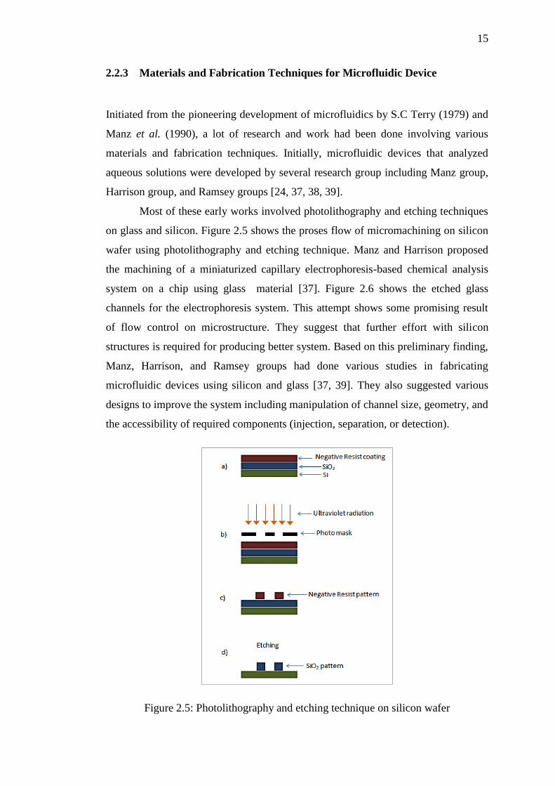
Most of these early works involved photolithography and etching techniques
on glass and silicon. Figure 2.5 shows the proses flow of micromachining on silicon
wafer using photolithography and etching technique. Manz and Harrison proposed
the machining of a miniaturized capillary electrophoresis-based chemical analysis
system on a chip using glass material [37]. Figure 2.6 shows the etched glass
channels for the electrophoresis system. This attempt shows some promising result
of flow control on microstructure. They suggest that further effort with silicon
structures is required for producing better system. Based on this preliminary finding,
Manz, Harrison, and Ramsey groups had done various studies in fabricating
microfluidic devices using silicon and glass [37, 39]. They also suggested various
designs to improve the system including manipulation of channel size, geometry, and
the accessibility of required components (injection, separation, or detection).
Figure 2.5: Photolithography and etching technique on silicon wafer

16
Figure 2.6: Capillary channels etched into Corning 7740 glass with 10 µm depth [37]
From these early studies, some problems about the suitability of the materials
and fabrication techniques were revealed. Silicon is however relatively expensive
and opaque, making it unsuitable for systems that use optical detection. Glass is
transparent, but it is amorphous which make the vertical side walls more difficult to
etch compare to silicon. Additionally, glass and silicon micromachining processes
are expensive, technically demanding, and time consuming. Based on these
problems, there has been rapid growth into many types of materials, especially
polymers. Polymers are inexpensive compared to silicon and glass. Channels can be
formed by moulding or embossing rather than etching. The device also can be sealed
thermally or by using adhesives. The development of polymer microfluidics was
mostly affected by the suitability of different type of polymer and the performance of
different fabrication techniques.
Most of the early attempt of polymer microfluidic fabrications was began
with thermoplastic polymers especially polymethylmethacrylate (PMMA),
polycarbonate (PC), and Cyclic Olefin Copolymer (COC). McCormick group
proposed injection moulding techniques for fabricating microchannel on PMMA
[40]. However, because of the complexity and high initial cost of the moulding
equipment and masters, injection moulding is rarely used for rapid prototyping.
Alternatively, hot embossing technique was introduced which was shown to be fast
and less expensive than injection moulding [41]. Figure 2.7 shows the concept of the
hot embossing technique for microchannel fabrication on plastic material. Many
common polymers had successfully hot embossed including PMMA and COC [42,
43].

17
Figure 2.7: Hot embossing technique for microchannel fabrication
Hot embossing technique is less expensive and possible for mass production.
However, it requires complicated equipment, robust mould, and lack of suitable
methods for good material bonding. Recent studies demonstrated simplified
equipment like the study done by Roy et al. and Young. They had demonstrated
improvement for the fabrication process using less expensive solid epoxy moulds
and convenient thermal bonding procedure [44, 45].
Then, in the same era, the laser ablation technique on thermoplastic polymers
including PMMA and PC was realized [46]. Figure 2.8 shows the illustration of the
laser ablation process for engraving microchannel on the plastic material. Laser
ablation technique for microfluidic fabrication was started by Roberts et al. This
technique is cost-accessible and able to produce complex 3D-multilayer structures
[47]. Some research had shown that this technique offers limited throughput and
fabricated channels showed greater surface roughness than hot embossed, or
injection moulded techniques. Recently, the works done by Huang et al. and Suriano
et al. had successfully showed reduced roughness on the sidewalls of the
microchannel [48, 49].
Figure 2.8: Laser ablation technique for microchannel fabrication
Mould

18
Even though there are many improvements in the fabrication technique,
thermoplastic polymers were observed to have severe drawbacks which limit the
range of microfluidic applications. Both PMMA and PC have opaque characteristic
which make them unsuitable for systems that require optical approach. The COC
material is unsuitable for biomedical application because it can lead to absorption of
specific compounds from biological fluids and causes clogging. Most of the
thermoplastic polymers also suffer from incompatibility with solvents used for the
biological assay and the surface chemistries are not well defined for surface
modifications.
Besides thermoplastic polymers, researcher also discovered the potential of
PDMS for microfluidic device [50, 51]. The fabrication of PDMS microfluidic was
started with the introduction of simpler soft lithography technique. Figure 2.9
describes the soft lithography process for PDMS microchannel fabrication. Soft
lithography technique on PDMS material was started by Duffy et al. [50]. Due to
this approach, PDMS has become a successful polymeric substrate material for rapid
prototyping. The advantages of PDMS for microfluidic technology can be seen in the
study done by Mac Donald et al. [51]. They had discovered that PDMS is
inexpensive, requires simple fabrication procedure, non-toxic, and able to form
multi-level microfluidic device. The study also described that PDMS material can be
sealed reversibly or irreversibly to many types of material.
Figure 2.9: Soft lithography technique for PDMS microchannel fabrication
Master mould

19
From past research works, it has been discovered that PDMS suffers from
some drawbacks including poor biocompatibility with few organic solvents. PDMS
also has unstable surface modification over time, able to absorb small molecules into
its matrix, and can deform under pressure. Several research in improving PDMS
microfluidic device was done including reducing molecule absorption and swelling
with silica particle and by sol-gel surface coating [52, 53]. Then, improvement was
performed to the PDMS microfluidic by controlling the deformation of the
microchannel [54].
Recently, a lot of researches are focusing in identifying polymers
complementary to PDMS, with similar fabrication procedures but, with higher
rigidity and better resistance to solvents. Fiorini et al. had explored the Thermoset
Polyester (TPE) [55, 56, 57]. Due to its higher rigidity, TPE is suggested as the
material of choice for application which has particularly high pressure or for
situations that demands fast flow-stabilization. The main limitation of TPE is its
unknown biocompatibility. Then, Kuo et al. had proposed Polyurethane
Methacrylate (PUMA) as a promising biocompatible material especially for micro-
devices in clinical situations [58, 59]. Bartolo et al. used Norland Adhesive 81
(NOA81) which proposed similar advantages as PUMA [60]. The limitation of
PUMA and NOA is weaker sealing strength compare to TPE but still higher than
PDMS. The channel deformation is also still visible with PUMA when pressures
increase. Researches on TPE, PUMA, and NOA show that they are promising
alternatives to PDMS for rapid prototyping that involve high pressure or
geometrically sensitive applications.
Based on the discussion of the materials and fabrication techniques for
microfluidic device, it described that each of them has their own suitability with
certain microfluidic applications and researcher should be wise in determining the
suitable materials for the microfluidic devices. More promising material and
fabrication technique should be investigated in order to produce better microfluidic
device in the future. The summarization of the reviews on microfluidic material is
shown in the Table 2.1.
20
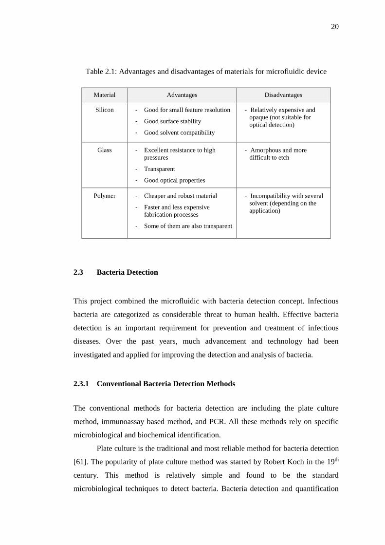
Table 2.1: Advantages and disadvantages of materials for microfluidic device
Material Advantages Disadvantages
Silicon - Good for small feature resolution
- Good surface stability
- Good solvent compatibility
- Relatively expensive and
opaque (not suitable for
optical detection)
Glass - Excellent resistance to high
pressures
- Transparent
- Good optical properties
- Amorphous and more
difficult to etch
Polymer - Cheaper and robust material
- Faster and less expensive
fabrication processes
- Some of them are also transparent
- Incompatibility with several
solvent (depending on the
application)
2.3 Bacteria Detection
This project combined the microfluidic with bacteria detection concept. Infectious
bacteria are categorized as considerable threat to human health. Effective bacteria
detection is an important requirement for prevention and treatment of infectious
diseases. Over the past years, much advancement and technology had been
investigated and applied for improving the detection and analysis of bacteria.
2.3.1 Conventional Bacteria Detection Methods
The conventional methods for bacteria detection are including the plate culture
method, immunoassay based method, and PCR. All these methods rely on specific
microbiological and biochemical identification.
Plate culture is the traditional and most reliable method for bacteria detection
[61]. The popularity of plate culture method was started by Robert Koch in the 19th
century. This method is relatively simple and found to be the standard
microbiological techniques to detect bacteria. Bacteria detection and quantification

21
using plate culture method involves with dilution and bacteria counting. In plate
culture, it is assumed that a single bacterial colony arises from a single cell. With
suitable dilution range, the individual colony can be counted and it can be used to
establish the bacteria concentration from original sample. From history, numerous
bacteria detection had been achieved using the plate culture method. Aycicek et al.
had successfully detected the salmonella, coliform and E. coli bacteria contamination
using the plate culture method [62]. From the traditional plate culture method,
researchers are still improving this method for better accuracy and possible detection
of more types of bacteria. For example, recently Deng et al. had improved the plate
culture method to detect the lactic acid bacteria [63]. From this research, the growth
and colony size of the bacteria was enhanced. Eventually, there are some drawbacks
of the traditional plate culture method including labour intensive, time consuming,
and utilizes significant amount of materials.
Immunoassay based method is a popular conventional method for
quantitative detection of bacteria. Immunoassay method is based on the specific
recognition of specific target by an antibody [64]. One of the most fundamental
immunoassay methods is the ELISA. ELISA technique can be classified into several
types including direct, competitive, and sandwich concepts. From review, the
immunology-based method has been widely used for bacteria detection. Several
researchers had successfully performed the detection of E. coli bacteria using the
immunological method [65-67]. Then, this method was also being used to detect the
salmonella bacteria [68, 69]. Even though immunological detection method had been
found to be faster and more sensitive than plate cell culture, this method is expensive
and more complicated.
Another conventional method for bacteria detection is the PCR technique.
This technique was introduced for almost 20 years ago. PCR method can detect
single bacteria based on single copy of target deoxyribonucleic acid (DNA)
sequence. This promising method detects the bacteria by amplifying target DNA
which led to more specific and sensitive detection. PCR can amplify the target DNA
to 1-million-fold in less than an hour [70]. PCR based detection method had been
used for wide range of bacteria. Choi and Lee, and Choi et al. used this method for
detection of salmonella bacteria [71, 72]. Then, Perry et al. had successfully detected
the Bacillus cereus bacteria using PCR method [7]. However, PCR method depends

22
on expensive and complicated measurement device which requires skilled workers to
carry out the analysis.
2.3.2 Bacteria Detection Technologies
In this project, it is important to suggest the most suitable detection technology that
can be integrated with the microfluidic device. For the past few years, much
advancement has been made for molecular diagnostics of infectious microorganisms.
It has been discovered that wide range of technology approaches can be used to
detect the harmful bacteria based on electrical, optical, chemical, and biological
signals [74]. Based on past works, most bacteria detection technologies are revolving
around the electro-chemical, optical, and piezoelectric properties.
Electrochemical based detection is one of the possible technologies for
detection and quantification of bacteria in microfluidic. Electrochemical detection
technique can be categorized into four methods; amperometric, potentiometric,
impedimetric, and conductometric that are respectively refer to the current, potential,
impedance, and conductance parameters. Amperometric, conductometric, and
potentiometric techniques are the most popular electrochemical technologies for
bacteria detection because these techniques have excellence sensitivity. A lot of
researchers have reported successful bacteria detection using amperometric
technique. They had successfully used amperometric biosensor technique to detect E.
coli and salmonella bacteria [75, 76]. Then, conductometric technique on the other
hand is combination of conductance and bio-recognition method. Muhammad Tahir
and Alocilja group had successfully produced a conductometric-based detector for E.
coli and salmonella bacteria as shown in Figure 2.10 [77].
Figure 2.10: Conductometric immunosensor construction [77]

23
Figure 2.10 shows the schematic diagram of the conductometric
immunosensor device developed by Muhammad Tahir and Alocilja. This device
showed a specific, sensitive, and low volume detection platform. In potentiometric
technique, the bio-recognition process is converted into a potential signal. Based on
the potentiometric detection concept, the electrical potential difference between two
electrodes at near zero current will be detected using the high impedance voltmeter.
Ercole et al. demonstrated the detection of E. coli bacteria using the potentiometric
technique on the Light-addressable potentiometric sensor (LAPS) [78]. From this
project, the potentiometric detection system was reported to be very sensitive and
fast. For the past few years, combination of impedance measurement and bio-
recognition had initiated the development of impedance biosensor for
electrochemical-based bacteria detection. The research done by Yang et al. had
demonstrated an impedance sensor using interdigitated microelectrode (IME) for
detection of salmonella bacteria [79]. Figure 2.11 shows the experimental setup of
the impedance analyzer with IME. The measurement was carried out for detection of
salmonella in milk sample. This research had shown a promising result which able to
identify impedance change for bacterial growth.
Figure 2.11: Impedimetric detection system with impedance analyzer and IME [79]
Optical detection is the most widely employed technique for bacteria
detection due to their sensitivity and selectivity. This method has diverse
measurement platforms including absorption, reflection, refraction,
chemiluminescence, fluorescence, and Raman spectroscopy. Among of all these
diversity, absorption and fluorescence platforms are the most popular for optical
24
detection approach. Absorption spectroscopy is the simplest optical detection
method. Ultraviolet (UV) and visible absorption spectroscopy is a well-established
technique in macro-scale and micro-scale diagnostics. From past research works,
changes in optical density are sufficient for diagnosis and analysis. Li et al. used
optical absorption approach on the microfluidics-based bio-sensing method. In this
work, they had successfully performed the detection of E. coli bacteria [80].
However, it has been discovered that optical absorption detection in microfluidic
devices suffers from poor detection limits. This is due to the short effective optical
path length in microchannel [81]. In the past few years, researchers had contributed
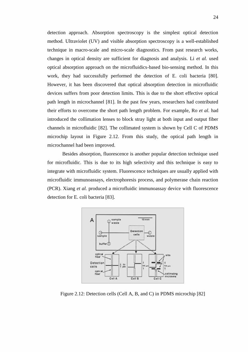
their efforts to overcome the short path length problem. For example, Ro et al. had
introduced the collimation lenses to block stray light at both input and output fiber
channels in microfluidic [82]. The collimated system is shown by Cell C of PDMS
microchip layout in Figure 2.12. From this study, the optical path length in
microchannel had been improved.
Besides absorption, fluorescence is another popular detection technique used
for microfluidic. This is due to its high selectivity and this technique is easy to
integrate with microfluidic system. Fluorescence techniques are usually applied with
microfluidic immunoassays, electrophoresis process, and polymerase chain reaction
(PCR). Xiang et al. produced a microfluidic immunoassay device with fluorescence
detection for E. coli bacteria [83].
Figure 2.12: Detection cells (Cell A, B, and C) in PDMS microchip [82]


![Untitled-1 [uralbeznarkotikov.ru]uralbeznarkotikov.ru/cat/paper/1-2016.pdf · 800 3333 118 8800 3333 118 "talbeznarkotihov.ru 8800 3333 8800 3333 118 8800 3333 118 B 800 3333 118](https://static.fdocuments.in/doc/165x107/5fa8ba52bd5e685c68532c8a/untitled-1-800-3333-118-8800-3333-118-talbeznarkotihovru-8800-3333-8800.jpg)