DESIGN AND DEVELOPMENT OF A ALTERNATE MECHANISM FOR STONE CRUSHER USING RELATIVE...
6
International Journal of Mechanical and Industrial Engineering (IJMIE), ISSN No. 2231 –6477, Vol-3, Iss-2, 2013 51 DESIGN AND DEVELOPMENT OF A ALTERNATE MECHANISM FOR STONE CRUSHER USING RELATIVE VELOCITY METHOD PROF. ANJALI J. JOSHI 1 , DR. JAYANT P. MODAK 2 1 Assistant Professor, 2 Dean R&D, Department of Mechanical Engineering, 1 MIT Academy of Engineering Alandi, Pune (M.S.) India 2 Priyadarshini College of Engineering, Nagpur (M.S) India Abstract- In this paper alternate mechanism for design and analysis of small size stone crusher mechanism is proposed. The basic idea is to optimize the design of the crusher which would be best suited for stone which need crushing force of 3 Tons. Presently for reducing sizes of stones from 10cm x 10cm to 2.5cm x 2.5cm in quarries is laborious job and is done manually our approach is to design a best optimum mechanism for said conditions. Keywords- Dynamic, d'Alembert's principle, Grashoff’s law, Force Analysis, Kinematic synthesis and analysis, Newton-Cotes quadrature formula, composite Trapezoidal rule, Sector gear, Static, Transmission Ratio. I. INTRODUCTION The proposed research is interested in providing an alternative mechanism which includes the position synthesis and analysis of a mechanism with rigid bodies (Links) interconnected by kinematic pairs (Joints) i.e. kinematic chains. This method, of completely geometrical nature, consists in determining the feasible configuration that a kinematic chain can adopt within the given ranges for its degrees of freedom; a configuration is an assignment of positions and orientations to all links that satisfy the kinematic constraints imposed by all joints. II. KINEMATIC SYNTHESIS OF PROPOSED (ALTERNATIVE MECHANISM) STONE CRUSHER The Proposed stone crusher consists of two mechanisms, which needs to be synthesized separately. 2.1) Crank and lever Mechanism 2.2) Double Rocker Mechanism. 2.1) Kinematic Synthesis of Crank and Lever Mechanism Basically this mechanism falls under class I of a four bar mechanism, in which the shortest link can make a full revolution relative to each of the others. The three longer links can only oscillate relative to each other.\ Fig -1 Synthesis of Crank and lever Mechanism Fig 1 Crank – lever mechanism is shown with the notation to be used. As the crank (Link 1) rotates the lever i.e. link 3 oscillates through an angle Ѳ. B 1 and B 2 are the two extreme positions of the pin at the end of the lever. A 1 and A 2 are the corresponding crank pin positions. Here it is important to note that the two swings of the lever do not take place during equal crank rotation angles. The four bar function is a “Quick Return Mechanism”. If the crank turns at a constant speed, the time ratio of two swings of the lever is T. R = 180 + ∝ 180 − ∝ …………… (1) The most common design problem in which, the angle of oscillation Ѳ and angle α (or the time ration, which determines α) are specified. Considering the following input as Time ratio T.R= 1.15, Ѳ = 40 0 and Length of lever = 100 cm. Substituting the value of T.R. in equation 1, α = 12.558 0 is determined. Detailed synthesis of the mechanism is carried out by Geometrical method and optimum parameters are obtained as follows. Crank Length – 27cm, Coupler – 195 cm, Lever – 100 cm, fixed Distance – 156 cm. Kinematic Synthesis of Double Rocker Mechanism This mechanism falls under Class II of four Bar mechanism, In which all members of this class no link can make a full revolution relative to any another.
Transcript of DESIGN AND DEVELOPMENT OF A ALTERNATE MECHANISM FOR STONE CRUSHER USING RELATIVE...

International Journal of Mechanical and Industrial Engineering (IJMIE), ISSN No. 2231 –6477, Vol-3, Iss-2, 2013
51
DESIGN AND DEVELOPMENT OF A ALTERNATE MECHANISM FOR
STONE CRUSHER USING RELATIVE VELOCITY METHOD
PROF. ANJALI J. JOSHI
1, DR. JAYANT P. MODAK
2
1Assistant Professor, 2Dean R&D, Department of Mechanical Engineering, 1MIT Academy of Engineering Alandi, Pune (M.S.) India
2Priyadarshini College of Engineering, Nagpur (M.S) India
Abstract- In this paper alternate mechanism for design and analysis of small size stone crusher mechanism is proposed. The basic idea is to optimize the design of the crusher which would be best suited for stone which need crushing force of 3 Tons. Presently for reducing sizes of stones from 10cm x 10cm to 2.5cm x 2.5cm in quarries is laborious job and is done manually our approach is to design a best optimum mechanism for said conditions. Keywords- Dynamic, d'Alembert's principle, Grashoff’s law, Force Analysis, Kinematic synthesis and analysis, Newton-Cotes quadrature formula, composite Trapezoidal rule, Sector gear, Static, Transmission Ratio.
I. INTRODUCTION
The proposed research is interested in providing an alternative mechanism which includes the position synthesis and analysis of a mechanism with rigid bodies (Links) interconnected by kinematic pairs (Joints) i.e. kinematic chains. This method, of completely geometrical nature, consists in determining the feasible configuration that a kinematic chain can adopt within the given ranges for its degrees of freedom; a configuration is an assignment of positions and orientations to all links that satisfy the kinematic constraints imposed by all joints. II. KINEMATIC SYNTHESIS OF PROPOSED
(ALTERNATIVE MECHANISM) STONE
CRUSHER
The Proposed stone crusher consists of two mechanisms, which needs to be synthesized separately.
2.1) Crank and lever Mechanism 2.2) Double Rocker Mechanism.
2.1) Kinematic Synthesis of Crank and Lever Mechanism
Basically this mechanism falls under class I of a four bar mechanism, in which the shortest link can make a full revolution relative to each of the others. The three longer links can only oscillate relative to each other.\
Fig -1 Synthesis of Crank and lever Mechanism
Fig 1 Crank – lever mechanism is shown with the notation to be used. As the crank (Link 1) rotates the lever i.e. link 3 oscillates through an angle Ѳ. B1 and B2 are the two extreme positions of the pin at the end of the lever. A1 and A2 are the corresponding crank pin positions. Here it is important to note that the two swings of the lever do not take place during equal crank rotation angles. The four bar function is a “Quick Return Mechanism”.
If the crank turns at a constant speed, the time ratio of two swings of the lever is
T. R =180+ ∝
180− ∝ …………… (1)
The most common design problem in which, the angle of oscillation Ѳ and angle α (or the time ration, which determines α) are specified. Considering the following input as Time ratio T.R= 1.15, Ѳ = 400 and Length of lever = 100 cm. Substituting the value of T.R. in equation 1, α = 12.5580 is determined. Detailed synthesis of the mechanism is carried out by Geometrical method and optimum parameters are obtained as follows. Crank Length – 27cm, Coupler – 195 cm, Lever – 100 cm, fixed Distance – 156 cm. Kinematic Synthesis of Double Rocker Mechanism This mechanism falls under Class II of four Bar mechanism, In which all members of this class no link can make a full revolution relative to any another.

Design and Development of a Alternate Mechanism for Stone Crusher Using Relative Velocity Method
International Journal of Mechanical and Industrial Engineering (IJMIE), ISSN No. 2231 –6477, Vol-3, Iss-2, 2013
52
Fig -2 Synthesis of Double rocker mechanism
Fig 2 Double rocker mechanism is shown with the notation to be used. As the Input rocker O2C (Link 3) oscillates, the other output rocker i.e. O3D (link5) oscillates through an angle φ. Considering the following input as Output Rocker Length O3D =50cm then fixed distance O3O2 = 80cm Input angle of oscillation = 400. Detailed synthesis of the mechanism is carried out by Geometrical method for various output angle of oscillation φ. (100, 150, 200) Since mechanism with output angle of oscillation φ
=100 satisfies the Grashoff’s law, following parameters
are obtained. Input Rocker Length - 12 cm, Coupler – 104cm
III.STATIC FORCE ANALYSIS
Graphical Method Analyses may be required for a number of mechanism positions; however, in many cases, critical maximum-force positions can be identified and graphical analyses performed for these positions only. An important advantage of the graphical approach is that it provides useful insight as to the nature of the forces in the physical system. Figure below shows the angular position of crank Ѳ=600
Fig-3 Static Force analysis – Graphical Method
The mechanism is analyzed graphically and ultimately the torque on the crank is computed. From the above Force polygon F45 =7.9 tons in the direction shown. Crushing force at the extension of output rocker is considered approx. 3 Tons. And Crank is rotating at an angular speed of 120 rpm (Anticlockwise)
F45 = -F54 = F34 = -F43 and F23 = 1.1 tons. F32 = -F23 = F12 =-F21=F61
Summing Moments about point O1 gives torque required on the crank. ∑MO1= TO1A+F21 x h = 0 …..(5)For equilibrium, the torque TO1A must be equal to F21 X h. This is shown in Fig. Because the cross-product F21 x h is clockwise, the torque must be anticlockwise.
Fig: 4 Torque required on crank
So we have calculated a torque required on the crank which is given in a tabulated form. Table: 1 Crank Angular Position with force and Torgue
required on crank
Srno. Crank
Angular Position
Coupler force on
Link AB (in
Tons)
Coupler force on
Link CD (in
Tons)
Torque required
on Crank O1A
(in Nm)
1 400 0.9 6.4 800
Clockwise
2 600 1.1 7.9 1042
Anti-
Clockwise
3 900 1.0 7.4 1430
Anti-
Clockwise
4 1200 0.9 6.8 2700
Anti-
Clockwise 5 1500 1.3 8 2600

Design and Development of a Alternate Mechanism for Stone Crusher Using Relative Velocity Method
International Journal of Mechanical and Industrial Engineering (IJMIE), ISSN No. 2231 –6477, Vol-3, Iss-2, 2013
53
Anti-
Clockwise
6 1800 0.8 7.4 960 Anti-
Clockwise
7 2250 1 7.2 900
Clockwise
8 2700 0.9 6.1 1980
Clockwise
9 3150 1.2 7 3120
Clockwise
10 3600 1.8 7.5 2880
Clockwise Above table indicates that maximum force in a revolution of crank on coupler AB is 1.8 Tons and on Coupler CD is 8 Tons. IV. DYNAMIC FORCE ANALYSYS –
GRAPHICAL METHOD
Dynamic force Analysis for Proposed Stone crusher uses d'Alembert's principle can be derived from Newton's second law.
( ) 0GF ma …………… (6)
( ) 0eG GT I ……………….. (7) e terms in parentheses in Eq. (6) and (7) are called the reverse-effective force and the reverse-effective Torque, respectively. These quantities are also referred to as inertia force and inertia torque. Thus, we define the inertia force F, as
Fi = -maG ………………….(8) Where F refers here to the summation of external
forces and eGT is the summation of external moments, or resultant external moment, about the center of mass G This reflects the fact that a body resists any change in its velocity by an inertia force proportional to the mass of the body and its acceleration. The inertia Force acts through the center of mass G of the body. The inertia torque or inertia couple C, is given by: i GC I … (9)
As indicated, the inertia torque is a pure torque or couple. From Equations (8) & (9), their directions are opposite to that of the accelerations. Substitution of Equation (8) and (9) into Equation (6) and (7) leads to equations that are similar to those used for static-force analysis:
0e iF F F ………………. (10)
0G eG iT T C ……………. (11)
Fig: 5 Dynamic Force Analyses – Graphical Method
V. CALCULATIONS
α2=at
ba/AB=4900/195 =25.128rad/s2………from
acceleration diagram aG2=3300N/cm2……………………..From acceleration diagram Allowable Strength=
S X Size Factor X Ignorance F
Reliability Factor X Stress concentration Factor………...(12)
= 16800 X 0.5 X 0.5
0.85 X 2.2 = 2245.989 N/cm2
But, AllowableStrength= Max .Force on link AB
Cross section of link AB………. (13)
2245.989 = 1.1 x 10000
Cross section of link AB
Cross section of link AB = 8.03 cm2 Selecting cross section of link AB as 4cm x 4cm , Similarly cross section of link CD as 8cm x 8cm m2 = Mass of Link AB = Mass density of Link x Volume of Link…………………… (14) =7.8 x 10-3 x 3 x 3 x195=24.34 Kg. IG2=Mass moment of Inertia of Link AB @ C.G. =
1
12 x Mass of Link AB x(Link AB) 2………… (15)
= 77114.7Kg-cm2
Similarly we have calculated, α3=at
o2b/O2B=4000/100=62.5rad/s2…………from
acceleration diagram
Design and Development of a Alternate Mechanism for Stone Crusher Using Relative Velocity Method
International Journal of Mechanical and Industrial Engineering (IJMIE), ISSN No. 2231 –6477, Vol-3, Iss-2, 2013
54
aG3= 2000 N/cm2……………………..From
acceleration diagram m3 = Mass of Link O2B = 12.48 Kg. IG3 = Mass moment of Inertia of Link O2B @ C.G. = 10400Kg-cm2
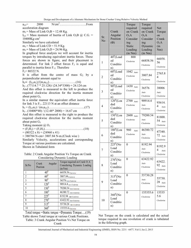
Similarly we have calculated m3 = Mass of Link CD = 51.9 Kg. m3 = Mass of Link O3D = 24.96 Kg. In graphical force analysis we will account for inertia torques by introducing equivalent inertia forces. These forces are shown in figure, and their placement is determined. For link 2 offset forces F2 is equal and parallel to inertia force F12. Therefore F2= 80322 N. It is offset from the centre of mass G2 by a perpendicular amount equal to h2= (IG2α2)/(m2aG2)……………………..(16) h2 = (77114.7 * 25.128)/ (24.34*3300) = 24.124 cm And this offset is measured to the left to produce the required clockwise direction for the inertia moment about point G2. In a similar manner the equivalent offset inertia force for link 3 is F3 = 22113 N at an offset distance h3 = (IG3α3) / (m3aG3)……………………………..(17) h3 = (10400*40) / (12.48* 2000) = 16.67 cm And this offset is measured to the right to produce the required clockwise direction for the inertia moment about point G3 Taking moment @ O1 = (F2H2) + (F3H3)………………………………..(18) = (80322 x 8) + (24960 x 41) = 380784 N-cm= 3807.84 N-m.(Clock wise ) Similarly Velocity, accelerations and corresponding Torque at various positions are calculated. Shown in Tabulated form
Table: 2 Crank Angular Position Vs Torque on Crank Considering Dynamic Loading
Table shows Total torque at various Crank Positions.
Table: 3 Crank Angular Position Vs Net Torque on Crank
Sr.No
Crank Angular Position (Ѳ)
Torque required on Crank O1A Considering Static Loading (in Nm)
Torque required on Crank O1A Considering Dynamic Loading (in Nm)
Net Torque on Crank O1A (in Nm)
1
400(Loaded Condition)
800
Clockwise 66858.56
Clockwise
66058.56
Clockwise
2
600(Loaded Condition)
1042 Anti-
Clockwise 3807.84
Clockwise
2765.84
Clockwise
3
900(Loaded Condition)
1430 Anti-
Clockwise 36576
Anti-
Clockwise
38006
Anti-
Clockwise
4
1200(Loaded Condition)
2700 Anti-
Clockwise 90914.4
Anti-
Clockwise
93614.4 Anti-
Clockwise
5
1500(Loaded Condition)
2600 Anti-
Clockwise 79200.54
Anti-
Clockwise
81800.54 Anti-
Clockwise
6
1800(Loaded Condition)
960 Anti-
Clockwise 46380.72 Anti-
Clockwise
47340.72 Anti-
Clockwise
7
2250(No Load Condition)
0 8192.94
Anti-
Clockwise
8192.94 Anti-
Clockwise
8
2700(No Load Condition)
0 63422.92 Anti-
Clockwise 63422.92 Anti-
Clockwise
9
3150(No Load Condition)
0 55730.28 Anti-
Clockwise 55730.28 Anti-
Clockwise
10
3600(No Load Condition)
0 155355.6
Clockwise 155355.6
Clockwise
Net Torque on the crank is calculated and the actual torque required in one revolution of crank is tabulated in the following graph.

Design and Development of a Alternate Mechanism for Stone Crusher Using Relative Velocity Method
International Journal of Mechanical and Industrial Engineering (IJMIE), ISSN No. 2231 –6477, Vol-3, Iss-2, 2013
55
Fig: 6 Graph of Total Torque On crank Vs One revolution of
crank Applying Newton-Cotes quadrature formula and composite Trapezoidal rule, Total area under this Curve is calculated which represents work done per revolutions. Work done per revolution=∫ T dθ = ∆Ѳ
2 [T1 +TN +2(T2 +T3+…….. TN-1)]…….. (21)
= -174071.768 Nm.rad(Anti-clockwise) Tmean = ∫ TdѲ
∫ dѲ ………………………………….(22)
= - 27704.38 Nm (i.e. Anticlockwise) Further mean torque is calculated which decides the other input parameters like drive rating, flywheel etc. Area under shaded portion gives a maximum fluctuation of energy based on which flywheel is designed. Based on design of complete stone crusher mechanism the other parameters of a stone crusher like design of Motor, belt drive, Flywheel design, gear box etc are decided. Figure given below shows a complete layout of small capacity stone crusher M-Motor V-B-V-Belt Drive, B1, B 2 -Bearings C-Coupling G-Gear Box O1-A-B-O2-C-D-O3-E-Mechanism of a stone Crusher
Fig: 6 Layout of small capacity stone crusher
Outcomes of calculations
Flywheel Parameters: Type of Flywheel: Solid disc geometry with inside and outside radius Type and Density of Material: Cast Iron with density as 7200 Kg/m3 Speed: 900 r. p. m. Inside radius: 46.7 cm Outside radius: 58.4 cm Thickness: 5.84cm Total mass of flywheel: 162.43 Kg Worm Gear Box: Specifications: Helical Gear Box, Speed Reduction ratio 7.5:1, Power: 498 KW V-Belt Drive For speed reduction from 1500 rpm to 910 rpm, Number of belts: 8 of type 5V1250, Type of Pulley 8V Grooves Sheaves of D Type. Motor: 425 KW, 4Pole, 1500rpm VI. PREVIOUS WORK
We have proposed one more design for same capacity [ref.1], in which we proposed the similar mechanism in which selection of crank and lever mechanism was different resulting which design parameters calculated was different. Like this we have design various mechanisms for same capacities by replacing double rocker mechanism with rack and sector gear mechanism.

Design and Development of a Alternate Mechanism for Stone Crusher Using Relative Velocity Method
International Journal of Mechanical and Industrial Engineering (IJMIE), ISSN No. 2231 –6477, Vol-3, Iss-2, 2013
56
VII. CONCLUSION
Similar machines can be designed which are of same capacities. Various designs may have advantages and disadvantages over one another. Based on generated data for various designs, mathematical model based on dimensional analysis can be designed. Further by multiple regressions method using MATLAB software the best and optimum model can be obtained. REFERENCES
[1]. Anjali J. Joshi, Dr. Jayant P. Modak, Design and Development
of a small capacity stone crusher mechanism, Indian Journal of Applied Research, Volume: 3, Issue: 2 February 2013, ISSN - 2249-555X
[2]. Dr. Louis G. Reifschneider, Teaching Kinematic Synthesis of Linkages without Complex Mathematics, journal of Industrial Technology, Volume 21, Number 4-October 2005 through December.
[3]. Dr. Habib, MEG 373“Kinematic and Dynamics of
Machinery”, Chapter 5 Force Analysis.
[4]. Jack A. Collins, Henery Busby, George Stoab, “Mechanical
Design of Machine Elements & Machines” Chapter 18
Flywheel and High –Speed Rotors.
[5]. Shriniwas S. Bali, Satish Chand, Transmission Angle in Mechanism (Triangle in mech), Pergamon Mechanism and Machine Theory 37(2002)175-195.
[6]. Kennth J. Waldron / Gary L. Kinzel, Kinematice, Dynamics,& Design of Machinery, edition 2007.
[7]. R.S. Khurmi and J.K. Gupta, Theory of Machines, edition 2002
[8]. Robert L.Norton,Machine Design,pearson Second edition.
[9]. Amitabha Ghosh and Ashok Kumar Mallik,Theory of Mechanisms and Machines,Third Edition Reprint 2008.
[10]. James G. Donovan Ph. D Thesis in Minning and Mineral Engineering, “Fracture toughness based models for the prediction of power consumption,product size, and capacity of jaw crushers” July 2003.
[11]. Robert L. Norton, Machine Design, pearson Second edition.