Design and Construction of the RF Electronic System at ... · with a 100-kW RF transmitter,...
4
DESIGN AND CONSTRUCTION OF THE RF ELECTRONIC SYSTEM AT TAIWAN PHOTON SOURCE F.-T. Chung#, M.-S. Yeh,T.-C. Yu ,Ch. Wang, L.-H. Chang, C.-H. Lo, M.-H. Tsai, M.-H. Chang, T.- C. Yu, L.-J. Chen, Z.-K. Liu, M.-C. Lin, P.-Y. Chen, C.-L. Tsai, National Synchrotron Radiation Research Center, Hsinchu 30076, Taiwan Abstract The RF electronic system at NSRRC was made fully in house by the RF group from design through construction to completion. The first RF electronic system includes an analogue LLRF system, a step motor, and an ARC module of a Petra cavity. It was successfully integrated with a 100-kW RF transmitter, high-power RF transfer system, and a cooling system and applied to the booster of TPS. Two duplicated RF electronic system were then applied to the storage ring but integrated with the 300- KW transmitters. With these RF systems, the TPS storage ring achieved beam current 100 mA on 2015 March 26. INTRODUCTION This article explains the architecture of the RF electronic system for Taiwan Photon Source (TPS). Modularization of the RF electronic subsystems can duplicate the subsequent second and third storage-ring RF electronic systems efficiently to operate individual RF plant in the first stage of TPS commissioning. The main objective of this article is the construction of the electronic system for booster RF plant, which has also a preliminary role for all RF plants. The principle of this design is to realize both local and remote monitoring and control of the RF cavity. The booster RF system can provide maximum accelerating voltage 1200 kV to boost the electron beam with maximum RF power 100 kW for nominal operation of the TPS booster ring. The planning and allocation of electric power, cooling water, cooling air, cable tray and signal cabling would be shown as a preliminary preparation for construction of the booster RF plant. The complete construction of the booster and storage ring RF plants were designed to support the first-stage commissioning of the synchrotron accelerator with target beam current 100 mA; the parameters of TPS [1] are listed in Table I. ELECTRIC UTILITY To construct operating environment of the RF plants, firstly the AC power was allocated as follows: (1) 3P4W (general AC power) 380V/220V 250/650A (2) 3P4W (general AC power) 208V/120V 32/40A (3) 3P4W (emergency AC power) 208V/120V 50/63A. The components of the RF system are distributed around the building according to their function. To manage efficiently the electric power to each rack and module for all these components in a balanced and safe condition, the original power racks must their capacity with anti-EMI pipes to the load as shown in Figure 1. Table 1: Parameters of the TPS Booster Ring Parameter Value injection energy 150 Mev extraction energy 3 GeV circumference 496.8 m harmonic number (h) 828 momentum compaction factor (alpha) 0.002474 repetition rate 3 Hz RF frequency 499.65 MHz energy spread (Linac to booster) 0.095 % Figure 1: Allocation of AC power for the TPS booster RF system. AC Power for Transmitter The RF transmitter requires general AC power of capacity 380 V/400 A through a cable (200 mm 2 , 400 A, Hypalon) and AC power (208 V/120 V) for the control panel through cable (22 mm 2 , 50 A). As the transmitter rack has its own circuit breaker, the power line can be simply plugged in. AC Power for Signal Controller The controller rack area collects the entire control system; emergency power with an uninterruptible power supply is hence required. Racks 3 and 4 integrate a 3P4W AC power distributor to each rack. As the circulator part requires low AC power, this power is supplied by Rack 8. AC Power for Cavity Control System The cavity of the booster ring requires emergency electric power at 110 V/20 A for the controller rack, general electric power at 220 V/25 A for the controller rack and general electric power at 110 V/20 A for the main breaker. 220 VAC is supplied to ion pumps. 6th International Particle Accelerator Conference IPAC2015, Richmond, VA, USA JACoW Publishing ISBN: 978-3-95450-168-7 doi:10.18429/JACoW-IPAC2015-WEPHA045 7: Accelerator Technology T07 - Superconducting RF WEPHA045 3215 Content from this work may be used under the terms of the CC BY 3.0 licence (© 2015). Any distribution of this work must maintain attribution to the author(s), title of the work, publisher, and DOI.
Transcript of Design and Construction of the RF Electronic System at ... · with a 100-kW RF transmitter,...
DESIGN AND CONSTRUCTION OF THE RF ELECTRONIC SYSTEM AT TAIWAN PHOTON SOURCE
F.-T. Chung#, M.-S. Yeh,T.-C. Yu ,Ch. Wang, L.-H. Chang, C.-H. Lo, M.-H. Tsai, M.-H. Chang, T.-C. Yu, L.-J. Chen, Z.-K. Liu, M.-C. Lin, P.-Y. Chen, C.-L. Tsai, National Synchrotron Radiation
Research Center, Hsinchu 30076, Taiwan
Abstract The RF electronic system at NSRRC was made fully in
house by the RF group from design through construction to completion. The first RF electronic system includes an analogue LLRF system, a step motor, and an ARC module of a Petra cavity. It was successfully integrated with a 100-kW RF transmitter, high-power RF transfer system, and a cooling system and applied to the booster of TPS. Two duplicated RF electronic system were then applied to the storage ring but integrated with the 300-KW transmitters. With these RF systems, the TPS storage ring achieved beam current 100 mA on 2015 March 26.
INTRODUCTION
This article explains the architecture of the RF electronic system for Taiwan Photon Source (TPS). Modularization of the RF electronic subsystems can duplicate the subsequent second and third storage-ring RF electronic systems efficiently to operate individual RF plant in the first stage of TPS commissioning. The main objective of this article is the construction of the electronic system for booster RF plant, which has also a preliminary role for all RF plants.
The principle of this design is to realize both local and remote monitoring and control of the RF cavity. The booster RF system can provide maximum accelerating voltage 1200 kV to boost the electron beam with maximum RF power 100 kW for nominal operation of the TPS booster ring. The planning and allocation of electric power, cooling water, cooling air, cable tray and signal cabling would be shown as a preliminary preparation for construction of the booster RF plant. The complete construction of the booster and storage ring RF plants were designed to support the first-stage commissioning of the synchrotron accelerator with target beam current 100 mA; the parameters of TPS [1] are listed in Table I.
ELECTRIC UTILITY
To construct operating environment of the RF plants, firstly the AC power was allocated as follows:
(1) 3P4W (general AC power) 380V/220V 250/650A (2) 3P4W (general AC power) 208V/120V 32/40A (3) 3P4W (emergency AC power) 208V/120V 50/63A.
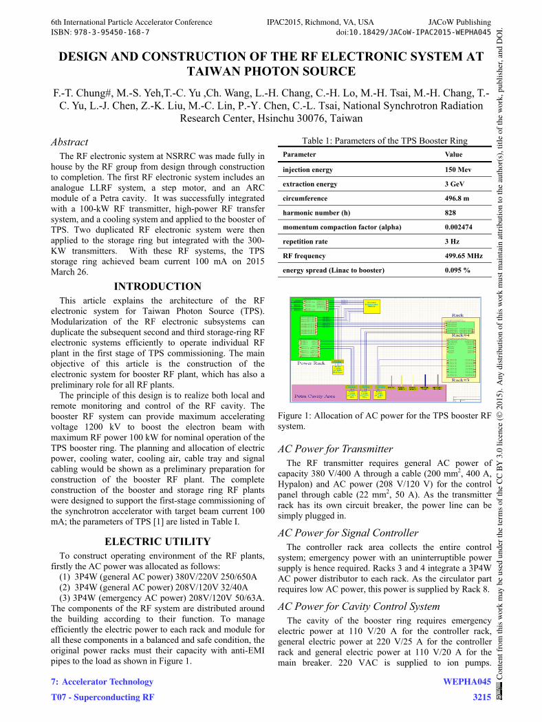
The components of the RF system are distributed around the building according to their function. To manage efficiently the electric power to each rack and module for all these components in a balanced and safe condition, the original power racks must their capacity with anti-EMI pipes to the load as shown in Figure 1.
Table 1: Parameters of the TPS Booster Ring
Parameter Value
injection energy 150 Mev
extraction energy 3 GeV
circumference 496.8 m
harmonic number (h) 828
momentum compaction factor (alpha) 0.002474
repetition rate 3 Hz
RF frequency 499.65 MHz
energy spread (Linac to booster) 0.095 %
Figure 1: Allocation of AC power for the TPS booster RF system.
AC Power for Transmitter The RF transmitter requires general AC power of
capacity 380 V/400 A through a cable (200 mm2, 400 A, Hypalon) and AC power (208 V/120 V) for the control panel through cable (22 mm2, 50 A). As the transmitter rack has its own circuit breaker, the power line can be simply plugged in.
AC Power for Signal Controller The controller rack area collects the entire control
system; emergency power with an uninterruptible power supply is hence required. Racks 3 and 4 integrate a 3P4W AC power distributor to each rack. As the circulator part requires low AC power, this power is supplied by Rack 8.
AC Power for Cavity Control System The cavity of the booster ring requires emergency electric power at 110 V/20 A for the controller rack, general electric power at 220 V/25 A for the controller rack and general electric power at 110 V/20 A for the main breaker. 220 VAC is supplied to ion pumps.
6th International Particle Accelerator Conference IPAC2015, Richmond, VA, USA JACoW PublishingISBN: 978-3-95450-168-7 doi:10.18429/JACoW-IPAC2015-WEPHA045
7: Accelerator TechnologyT07 - Superconducting RF
WEPHA0453215
Cont
entf
rom
this
wor
km
aybe
used
unde
rthe
term
soft
heCC
BY3.
0lic
ence
(©20
15).
Any
distr
ibut
ion
ofth
isw
ork
mus
tmai
ntai
nat
tribu
tion
toth
eau
thor
(s),
title
ofth
ew
ork,
publ
isher
,and
DO
I.
Emergency power is used for local controllers such as step motors, water-flow meters, temperature modules and arc detectors. Other general AC power is used for ion pumps of other types.
AC Power for Air-cooling Devices At the loading area, a set of breakers (3 W 208 VAC,
25 A) is required for an inverter and turbo fan. This setup supplies air to cool the ceramic window of the Petra cavity in the long term. For a switch for the rate of air flow we adopted Barks (dale-D1H A3SS).
AC Power and Signal Connections As the RF cavity, controller and AC power are located in separate areas, connections between these areas are required. The signal cable and AC power cable must be separated. The size of signal cable trays is 600 mm x 100 mm; the AC power cable tray has size 300 mm x 100 mm. Cable trays of two sizes are adopted in the controller area. As the space of the loading area is limited, a double-layer tray is not feasible; thus a single 600 mm x 100 mm size is here adopted. If electric power were required, an AC power line would be shielded in a metal pipe to diminish the electromagnetic interference to the signal cables, as shown in Figure 2.
Figure 2: Arrangements of signal (blue) and AC-power (red) trays are set as a double layer in the controller area, but as a single layer in the loading area (blue).
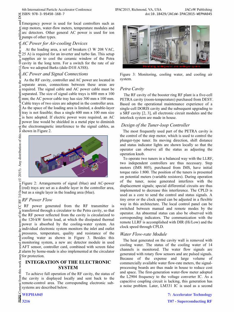
RF Power Flow RF power generated from the RF transmitter is transferred through a circulator to the Petra cavity, so that the RF power reflected from the cavity is circularized to the 120-kW ferrite load, at which the dissipated thermal power is absorbed by the cooling-water system. An individual electronic system monitors the inlet and outlet pressures, temperature, quality and resistance of the cooling water as shown in Figure 3. Besides this monitoring system, a new arc detector module in used AFT sensor, controller card, combined with screen false alarm by home-made is also implemented at the circulator for protection.
INTEGRATION OF THE ELECTRONIC SYSTEM
To achieve full operation of the RF cavity, the status of the cavity is displayed locally and sent back to the remote-control area. The corresponding electronic sub-systems are described below.
Figure 3: Monitoring, cooling water, and cooling air system.
Petra Cavity The RF cavity of the booster ring RF plant is a five-cell
PETRA cavity (room-temperature) purchased from DESY. Based on the operational maintenance experience of a single-cell DORIS cavity and the subsequent upgrading to a SRF cavity [2, 3], all electronic circuit modules and the interlock system are made in house.
Design of the Tuner-loop Controller The most frequently used part of the PETRA cavity is the control of the step motor, which is used to control the plunger-type tuner. Its moving direction, shift distance and status indicator lights are shown locally so that the operator can observe all the status as adjusting the operation knob. To operate two tuners in a balanced way with the LLRF, two independent controllers are thus necessary. Step motors (IMS 805), purchased from IMS, have initial torque ratio 1:800. The position of the tuners is presented on potential meters (variable resistors). During operation of the tuner, noise generated interferes with the displacement signals; special differential circuits are thus implemented to decrease this interference. The CPLD is used as a core to send the control and status signals. A tiny error or the clock speed can be adjusted in a flexible way in this architecture. The local control panel can be switched between manual and remote modes by the operator. An abnormal status can also be observed with corresponding indicators. The communication with the remote LLRF is accomplished with DIR (Hi/Low) and the clock speed through CPLD.
Water Flow-rate Module The heat generated on the cavity wall is removed with cooling water. The status of the cooling water of 14 channels is monitored. The water flow signals are generated with rotary flow sensors and are pulsed signals. Because of the expense and large volume of commercially available water flow-rate meters, the signal-processing boards are thus made in house to reduce cost and space. The first-generation water-flow meter adopted the L2904 frequency to the voltage converter IC. As a capacitive coupling circuit is lacking, this generation has a noise problem. Later, LM331 IC is used as a second
6th International Particle Accelerator Conference IPAC2015, Richmond, VA, USA JACoW PublishingISBN: 978-3-95450-168-7 doi:10.18429/JACoW-IPAC2015-WEPHA045
WEPHA0453216
Cont
entf
rom
this
wor
km
aybe
used
unde
rthe
term
soft
heCC
BY3.
0lic
ence
(©20
15).
Any
distr
ibut
ion
ofth
isw
ork
mus
tmai
ntai
nat
tribu
tion
toth
eau
thor
(s),
title
ofth
ew
ork,
publ
isher
,and
DO
I.
7: Accelerator TechnologyT07 - Superconducting RF
edition to improve the noise problem in the upgraded version.
Upgrading the ARC Module The main part of the arc detector is the light detector. The original arc detector module made by AFT is too sensitive and thus generates false alarms. It was therefore improved, mainly with the CPLD adopted with a digital filter function to improve the correctness of signals. Meanwhile, the display panel would record the first detecting indication but without tripping the system. A latch function is not implemented on the arc-detector modules that are located inside the tunnel. For those arc detectors of the interlock sum on LLRF positioned outside the tunnel, a trip signal becomes triggered and latched locally by LLRF when there are continuous within 40 s.
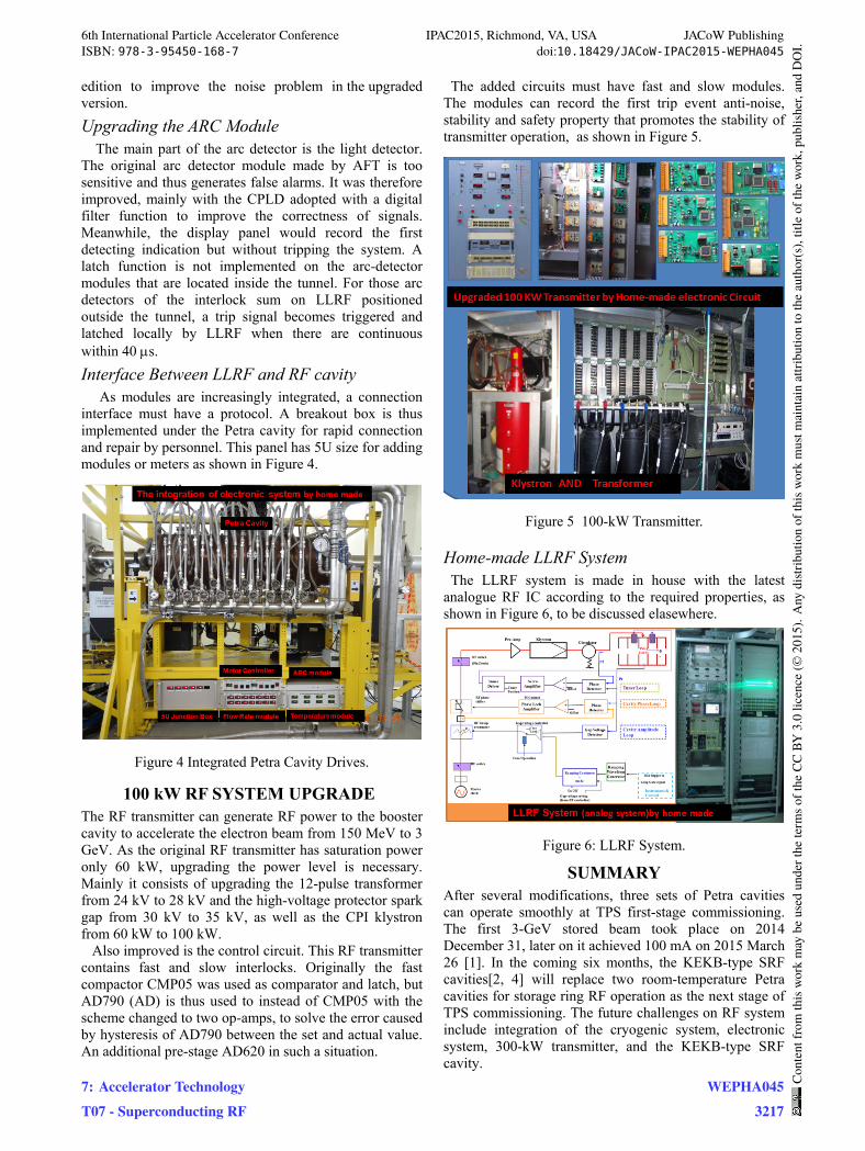
Interface Between LLRF and RF cavity As modules are increasingly integrated, a connection interface must have a protocol. A breakout box is thus implemented under the Petra cavity for rapid connection and repair by personnel. This panel has 5U size for adding modules or meters as shown in Figure 4.
Figure 4 Integrated Petra Cavity Drives.
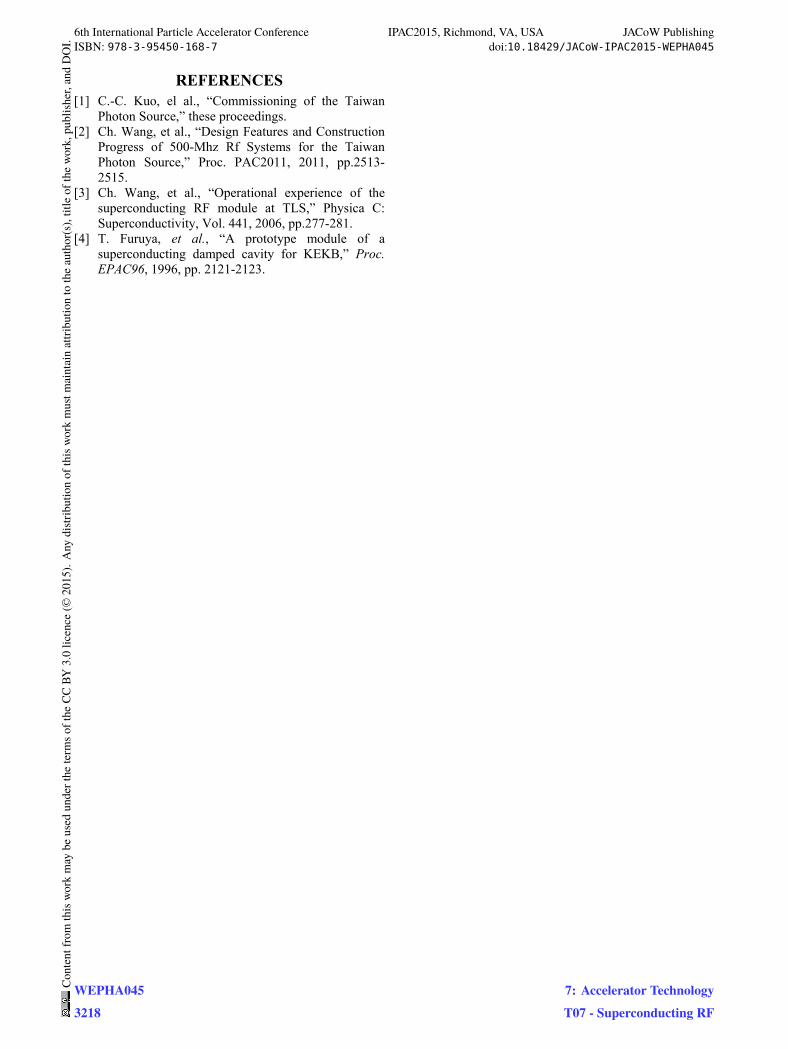
100 kW RF SYSTEM UPGRADE The RF transmitter can generate RF power to the booster cavity to accelerate the electron beam from 150 MeV to 3 GeV. As the original RF transmitter has saturation power only 60 kW, upgrading the power level is necessary. Mainly it consists of upgrading the 12-pulse transformer from 24 kV to 28 kV and the high-voltage protector spark gap from 30 kV to 35 kV, as well as the CPI klystron from 60 kW to 100 kW. Also improved is the control circuit. This RF transmitter contains fast and slow interlocks. Originally the fast compactor CMP05 was used as comparator and latch, but AD790 (AD) is thus used to instead of CMP05 with the scheme changed to two op-amps, to solve the error caused by hysteresis of AD790 between the set and actual value. An additional pre-stage AD620 in such a situation.
The added circuits must have fast and slow modules. The modules can record the first trip event anti-noise, stability and safety property that promotes the stability of transmitter operation, as shown in Figure 5.
Figure 5 100-kW Transmitter.
Home-made LLRF System The LLRF system is made in house with the latest analogue RF IC according to the required properties, as shown in Figure 6, to be discussed elasewhere.
Figure 6: LLRF System.
SUMMARY After several modifications, three sets of Petra cavities can operate smoothly at TPS first-stage commissioning. The first 3-GeV stored beam took place on 2014 December 31, later on it achieved 100 mA on 2015 March 26 [1]. In the coming six months, the KEKB-type SRF cavities[2, 4] will replace two room-temperature Petra cavities for storage ring RF operation as the next stage of TPS commissioning. The future challenges on RF system include integration of the cryogenic system, electronic system, 300-kW transmitter, and the KEKB-type SRF cavity.
6th International Particle Accelerator Conference IPAC2015, Richmond, VA, USA JACoW PublishingISBN: 978-3-95450-168-7 doi:10.18429/JACoW-IPAC2015-WEPHA045
7: Accelerator TechnologyT07 - Superconducting RF
WEPHA0453217
Cont
entf
rom
this
wor
km
aybe
used
unde
rthe
term
soft
heCC
BY3.
0lic
ence
(©20
15).
Any
distr
ibut
ion
ofth
isw
ork
mus
tmai
ntai
nat
tribu
tion
toth
eau
thor
(s),
title
ofth
ew
ork,
publ
isher
,and
DO
I.
REFERENCES [1] C.-C. Kuo, el al., “Commissioning of the Taiwan
Photon Source,” these proceedings. [2] Ch. Wang, et al., “Design Features and Construction
Progress of 500-Mhz Rf Systems for the Taiwan Photon Source,” Proc. PAC2011, 2011, pp.2513-2515.
[3] Ch. Wang, et al., “Operational experience of the superconducting RF module at TLS,” Physica C: Superconductivity, Vol. 441, 2006, pp.277-281.
[4] T. Furuya, et al., “A prototype module of a superconducting damped cavity for KEKB,” Proc. EPAC96, 1996, pp. 2121-2123.
6th International Particle Accelerator Conference IPAC2015, Richmond, VA, USA JACoW PublishingISBN: 978-3-95450-168-7 doi:10.18429/JACoW-IPAC2015-WEPHA045
WEPHA0453218
Cont
entf
rom
this
wor
km
aybe
used
unde
rthe
term
soft
heCC
BY3.
0lic
ence
(©20
15).
Any
distr
ibut
ion
ofth
isw
ork
mus
tmai
ntai
nat
tribu
tion
toth
eau
thor
(s),
title
ofth
ew
ork,
publ
isher
,and
DO
I.
7: Accelerator TechnologyT07 - Superconducting RF