Design and Construction of Reinforced Embankments Over...
14
26 TRANSPORTATION RESEARCH RECORD 115:: Design and Construction of Reinforced Embankments Over Weal< Foundations RUDOLPH BONAPARTE AND BARRY R. CHRISTOPHER Experience with design and construction of reinforced em- bankments over saturated clay foundations is reviewed. Rein- forcement materials considered are geotextiles and geogrids. The effects of tensile reinforcement include increased embank- ment stiffness and reduced shear stress and strain magnitudes and plastic deformations in the foundation. Analysis results show that reinforcement reduces embankment settlement and lateral spreading due to undrained constant-volume distortion. The conditions under which these performance improvements are significant are described. Limit equilibrium design pro- cedures are discussed. Available information indicates that modified classical stability procedures are suitable for rela- tively uniform clay foundations. Their applicability to peat foundations appears to be more limited. Aspects of limit equi- librium analyses specific to use of reinforcement are discussed. These include (a) effect of the reinforcement force, (b) orienta- tion of reinforcement force, ( c) selection of reinforcement force for design, and (d) reinforcement embedment length. Simple design charts and figures presented can be used to make a preliminary assessment of overall factors of safety against foundation bearing capacity and slip surface failures and lat- eral sliding of the embankment. Last, construction aspects are described. Tensile reinforcing elements may be used to increase the sta- bility of embankments constructed over weak foundations. In this type of application, horizontal strips or layers of reinforce- ment are placed on the natural soil or within the base of the embankment with the remainder of the embankment con- structed in the conventional manner. Materials used as tensile reinforcement include steel strips, bars, or meshes (1 ), geotex- tiles (2-5), geogrids (6, 7), and other materials. In this paper, the use of polymer-based reinforcing elements such as geotex- tiles and geogrids is addressed. The use of steel reinforcement is described by Duncan et al. in another paper in this Record. Reinforced embankments over weak foundations typically fall into one of two categories (8). The more common category consists of embankments, dikes, or levees constructed over soft, saturated silt, clay, or peat layers (Figure la). In this category, the reinforcement is typically placed with its strong direction perpendicular to the centerline of the embankment, and plane-strain conditions are assumed to prevail. Additional reinforcement with its strong direction oriented parallel to the centerline may also be required at the ends of the embankment. The second category of reinforced embankment applications consists of those in which the foundation below the embank- ment is locally weak and the role of the reinforcement is to R. Bonaparte, GeoServices Inc., Consulting Engineers, 5950 Live Oak Pkwy., Norcross, Ga. 30093. B. R. Christopher, STS Consultants Ltd., 11 Pfingsten Rd., Northbrook, Ill. 60062. bridge over the weak zones or voids. These zones or voids may be caused by sinkholes, thawing ice, old stream beds, or pockets of silt, clay, or peat (Figure lb). In this category of applications, tensile reinforcement may be required in more than one direction, and thus the strips or layers of reinforcing material may be placed with varied orientations with respect to the embankment centerline. Reinforcement design for the case of an embankment over a void has typically been based on the conservative assumption (7, 9, 10) that the reinforcement acts as a tensioned membrane supporting the full overburden pres- sure (Figure 2). The equations shown in Figure 2 are from Giroud (9). T is the tensile force per unit width in the reinforce- ment; an approximate value for the reinforcement stiffness required to span a circular void of diameter b can be obtained by dividing K by 2. This second category of applications will not be discussed further. MECHANISMS OF REINFORCEMENT FOR EMBANKMENTS OVER WEAK FOUNDATION LAYERS The mechanism of reinforcement for an embankment con- structed over a uniform deposit of saturated clay is to stiffen the base of the embankment and reduce shear stress magnitudes and plastic shear deformations in the fowidation. This mecha- nism is illustrated in the results from a recent investigation by Low and Dunca.1 (11), who used finite element a.1alyses that included nonlinear (hyperbolic) soil stress-strain behavior. Their analyses showed that tensile reinforcement placed at or near the base of an embankment increased the stiffness of the embankment fill. This increase was proportional to the tensile stiffness K (reinforcement tensile modulus multiplied by rein- forcement cross sectional area per unit width) of the reinforce- ment. Only part of the mobilized tensile force went into stiffen- ing the embankment fill. The rest of the tensile force was transferred from the stiff reinforced fill to the less stiff founda- tion soil below the reinforced zone. The average shear stress and strain levels in the foundation were thereby reduced. The combined effects of increased fill stiffness and reduced shear stresses and strains in the foundation soil include reduced undrained (constant-volume) foundation distortion beneath the embankment as well as reduced embankment spreading and initial (undrained) embankment settlements. These effects are illustrated in Figure 3 for an embankment on a saturated clay foundation with an umeinforced factor of safety (FS) of just less than 1.0 and a ratio of foundation depth to crest width (DI B) equal to 0.36. [This DI B ratio and low unreinforced FS were selected to highlight the effect of reinforcement. A larger
Transcript of Design and Construction of Reinforced Embankments Over...
26 TRANSPORTATION RESEARCH RECORD 115::
Design and Construction of Reinforced Embankments Over Weal< Foundations
RUDOLPH BONAPARTE AND BARRY R. CHRISTOPHER
Experience with design and construction of reinforced embankments over saturated clay foundations is reviewed. Reinforcement materials considered are geotextiles and geogrids. The effects of tensile reinforcement include increased embankment stiffness and reduced shear stress and strain magnitudes and plastic deformations in the foundation. Analysis results show that reinforcement reduces embankment settlement and lateral spreading due to undrained constant-volume distortion. The conditions under which these performance improvements are significant are described. Limit equilibrium design procedures are discussed. Available information indicates that modified classical stability procedures are suitable for relatively uniform clay foundations. Their applicability to peat foundations appears to be more limited. Aspects of limit equilibrium analyses specific to use of reinforcement are discussed. These include (a) effect of the reinforcement force, (b) orientation of reinforcement force, ( c) selection of reinforcement force for design, and (d) reinforcement embedment length. Simple design charts and figures presented can be used to make a preliminary assessment of overall factors of safety against foundation bearing capacity and slip surface failures and lateral sliding of the embankment. Last, construction aspects are described.
Tensile reinforcing elements may be used to increase the stability of embankments constructed over weak foundations. In this type of application, horizontal strips or layers of reinforcement are placed on the natural soil or within the base of the embankment with the remainder of the embankment constructed in the conventional manner. Materials used as tensile reinforcement include steel strips, bars, or meshes (1 ), geotextiles (2-5), geogrids (6, 7), and other materials. In this paper, the use of polymer-based reinforcing elements such as geotextiles and geogrids is addressed. The use of steel reinforcement is described by Duncan et al. in another paper in this Record.
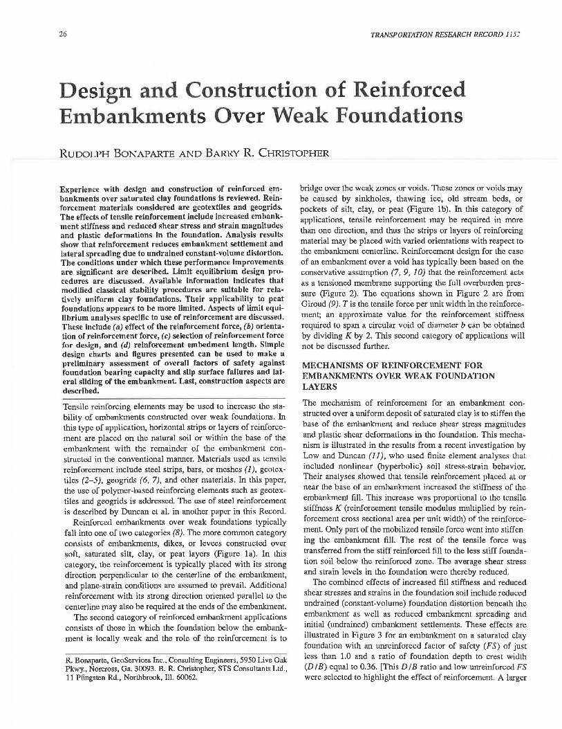
Reinforced embankments over weak foundations typically fall into one of two categories (8). The more common category consists of embankments, dikes, or levees constructed over soft, saturated silt, clay, or peat layers (Figure la). In this category, the reinforcement is typically placed with its strong direction perpendicular to the centerline of the embankment, and plane-strain conditions are assumed to prevail. Additional reinforcement with its strong direction oriented parallel to the centerline may also be required at the ends of the embankment.
The second category of reinforced embankment applications consists of those in which the foundation below the embankment is locally weak and the role of the reinforcement is to
R. Bonaparte, GeoServices Inc., Consulting Engineers, 5950 Live Oak Pkwy., Norcross, Ga. 30093. B. R. Christopher, STS Consultants Ltd., 11 Pfingsten Rd., Northbrook, Ill. 60062.
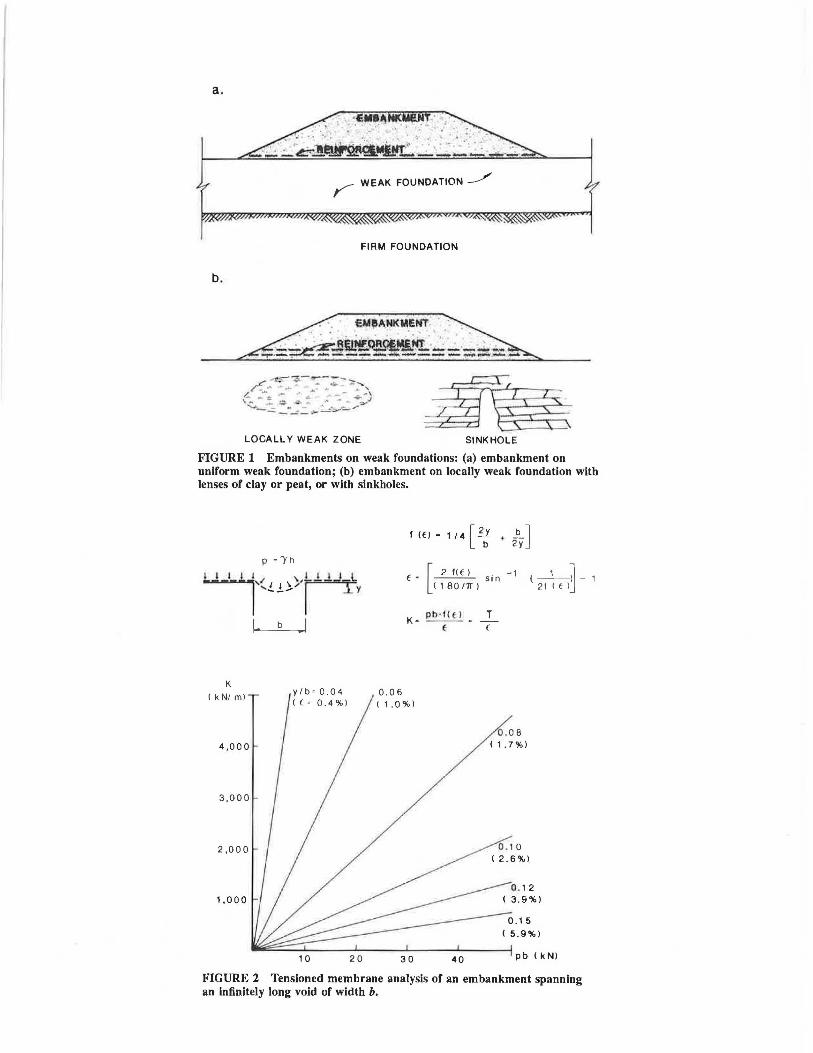
bridge over the weak zones or voids. These zones or voids may be caused by sinkholes, thawing ice, old stream beds, or pockets of silt, clay, or peat (Figure lb). In this category of applications, tensile reinforcement may be required in more than one direction, and thus the strips or layers of reinforcing material may be placed with varied orientations with respect to the embankment centerline. Reinforcement design for the case of an embankment over a void has typically been based on the conservative assumption (7, 9, 10) that the reinforcement acts as a tensioned membrane supporting the full overburden pressure (Figure 2). The equations shown in Figure 2 are from Giroud (9 ). T is the tensile force per unit width in the reinforcement; an approximate value for the reinforcement stiffness required to span a circular void of diameter b can be obtained by dividing K by 2. This second category of applications will not be discussed further.
MECHANISMS OF REINFORCEMENT FOR EMBANKMENTS OVER WEAK FOUNDATION LAYERS
The mechanism of reinforcement for an embankment constructed over a uniform deposit of saturated clay is to stiffen the base of the embankment and reduce shear stress magnitudes and plastic shear deformations in the fowidation. This mechanism is illustrated in the results from a recent investigation by Low and Dunca.1 (11), who used finite element a.1alyses that included nonlinear (hyperbolic) soil stress-strain behavior. Their analyses showed that tensile reinforcement placed at or near the base of an embankment increased the stiffness of the embankment fill. This increase was proportional to the tensile stiffness K (reinforcement tensile modulus multiplied by reinforcement cross sectional area per unit width) of the reinforcement. Only part of the mobilized tensile force went into stiffening the embankment fill. The rest of the tensile force was transferred from the stiff reinforced fill to the less stiff foundation soil below the reinforced zone. The average shear stress and strain levels in the foundation were thereby reduced.
The combined effects of increased fill stiffness and reduced shear stresses and strains in the foundation soil include reduced undrained (constant-volume) foundation distortion beneath the embankment as well as reduced embankment spreading and initial (undrained) embankment settlements. These effects are illustrated in Figure 3 for an embankment on a saturated clay foundation with an umeinforced factor of safety (FS) of just less than 1.0 and a ratio of foundation depth to crest width (DI B) equal to 0.36. [This DI B ratio and low unreinforced FS were selected to highlight the effect of reinforcement. A larger
a.
r WEAK FOUNDATION ____./
FIRM FOUNDATION
b.
E~l\~K~ENT
~-~~~ru.~~~ . ._:::~ --~-----~~~-~----------
LOCALLY WEAK ZONE SINKHOLE
FIGURE 1 Embankments on weak foundations: (a) embankment on uniform weak foundation; (b) embankment on locally weak foundation with lenses of clay or peat, or with sinkholes.
K
( kN/ ml
4 ,00 0
3,000
2 ,ODO
1,000
10 20
£ - [ 2 f( t ) . -1 c SI n
( 1BO111") (-1_)_ 1
21 ( t lJ
0.06 (, .0%)
30 40
0 . 0 B ( 1 . 7 % )
( 5.9%)
pb < kNl
FIGURE 2 Tensioned membrane analysis of an embankment spanning an Infinitely long void of width b.

28
a. FOUNDATION MATTRESS
3.3 FT.
1,-.·-~28'
TRANSPORTATION RESEARCH RECORD 1153
H ( 1 2·)
IL _ HORIZONTAL -
FOUNDATION DISPLACEMENT
0 i' 2' 3' 4' •-+-f--1-------l
D ( 20')
b.
c.
d.
MID SLOPE
Toe
+ p
Top
'Y - 11 Opel
Cu - 250psl
~u - 0
of Slope g
i 2
00
Ill
~ _c; c: ::::!' ~-eo ::: ~E -o :i:: -;v:: <l (/) 0 m
c
_.,,
;~ fvl ~~ - - - - - .- _ _ _ - -.":·;Y ~ o ~-----~-I 0 ~:'_ = ............... ...... ... ........ .. ................ . 00 -·~--. ___ .. ,,,_,. c Ex
o2 <l -2.0 N ~
· ~(I)
o_ Io
K(k/fl)
0 -·- 23 .. . .... 70 ----210 v
T
/ /
. • .. · --.-·-· .... ·······
----
a
10 Ill Ill
~ B 0
::::!' c:
6 c: ·~
4 cii 0 c:
2 0 N ... 0 :i::
~ ~
" w
FIGURE 3 Behavior of embankments with varying reinforcement stiffnesses constructed over a uniform weak foundation layer.
unreinforced FS and larger or smaller D/B would show a smaller influence of the reinforcement. Rowe and Soderman (12) discuss the influence of D/B.] The results in Figure 3 were predicted by Low and Duncan (11), who used nonlinear finite element analysis to analyze the embankment-foundation matiress system shown in the figure. The mattress consisted of a
1-m-thick geogrid-reinforced zone that was assumed to have uniform tensile stiffness. Low and Duncan (11) also showed that the influence of this mattress on embankment performance is roughly equivalent to that of a single layer of reinforcement of similar tensile stiffness located at the mid-height elevation of the mattress. On the basis of Low and Duncan's work, as well
Bonaparte and Christopher
as that of Rowe and his coworkers (12-17), and others [summarized by Christopher and Holtz (18)], a number of general observations can be made with respect to the beneficial effects of reinforcement placed at or near the base of embankments built over weak foundation layers:
1. Tensile reinforcement reduces displacements beneath the embankment centerline and heave near the embankment toe caused by undrained, constant-volume deformation. Tensile reinforcement also reduces vertical and horizontal displacements in the embankment.
2. By reducing the magnitude of shear deformations at the foundation-embankment interface, reinforcement decreases the average shear stress and shear strain magnitudes and the extent of the plastic zone in the foundation.
3. The improvements described in embankment performance increase with increasing mobilized reinforcement force. For a given embankment, the mobilized reinforcement force increases with increasing reinforcement tensile stiffness and decreasing foundation soil modulus (strength). The performance improvements can be significant for embankments with unreinforced factors of safety less than one (Figure 3) but decrease for unreinforced FS values much above 1. All other factors being equal, the mobilized reinforcement force increases with increasing DI B, up to DI B approximately equal to 0.4. For deep deposits with DI B greater than about 0.8, the mobilized reinforcement force will be small (12).
4. Tensile reinforcement may increase the height to which many types of embankments can be constructed without inducing a foundation failure. Alternatively, for a given embankment height, tensile reinforcement increases the factor of safety against foundation failure.
5. The reduction in shear stress and strain magnitudes in the foundation due to reinforcement is largest at shallow depths. A decrease in shear stress magnitude at shallow depths is important for sites at which a desiccated crust is underlain by saturated clay that exhibits a normally consolidated strength profile. In these cases, shear stresses will be reduced in the zone of minimum shear strength just below the crust and the failure surface will be forced deeper into stronger soil (19, 20).
The reinforcement does nothing to increase the strength of the foundation soil. Therefore the foundation soil must have adequate strength to support the entire reinforced embankment. If the embankment is made very stiff through sufficient reinforcement, it may behave as a semirigid mat, and the critical failure mechanism becomes one of bearing capacity of the entire embankment. At that point, additional reinforcement will not further increase embankment stability. Also, reinforcement does not significantly reduce overall embankment settlement owing to consolidation of the foundation soil.
DESIGN OF REINFORCED EMBANKMENTS OVER WEAK FOUNDATION LAYERS
This section of the paper deals solely with the end-of-construction design of reinforced embankments over weak foundation layers. Locally weak foundations are not addressed. Primary emphasis is on uniform, purely cohesive foundation deposits, although some reference is made to peats. The reader is referred to the work of Rowe et al. for peats (12-17).
29
Mechanisms of Failure
Published case studies (11, 13, 16) have shown that nonlinear finite element analyses can be used to evaluate the load-deformation response of embankments built over uniform weak foundations. However, the large majority of projects are designed using limit equilibrium procedures that evaluate a number of idealized failure mechanisms. The three failure mechanisms most often considered are (18, 21, 22)
• Overall bearing capacity failure of the foundation that may occur if the foundation is so weak that it cannot support the weight of the embankment;
• Lateral sliding of a portion of the embankment that may occur along the embankment-reinforcement interface, along the foundation-reinforcement interface, or along a shallow, weak seam or layer in the foundation soil; and
• Slip surface failure through the embankment and foundation.
Overall Bearing Capacity
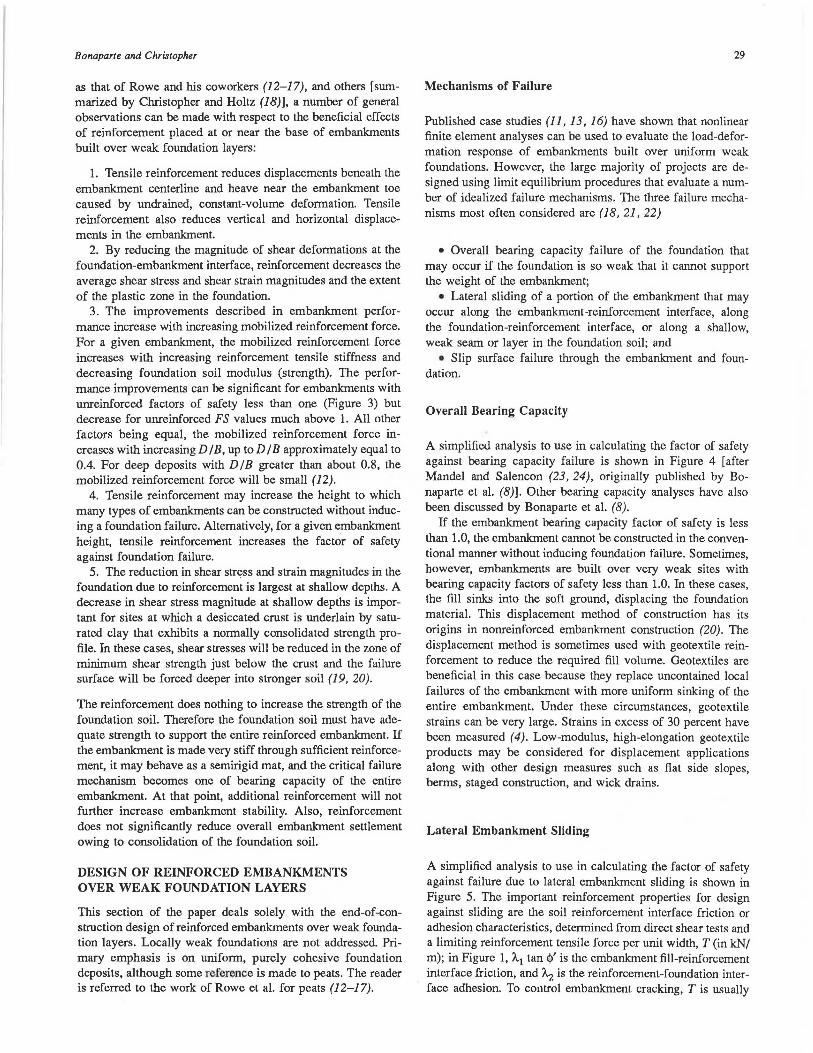
A simplified analysis to use in calculating the factor of safety against bearing capacity failure is shown in Figure 4 [after Mandel and Salencon (23, 24), originally published by Bonaparte et al. (8)]. Other bearing capacity analyses have also been discussed by Bonaparte et al. (8).
If the embankment bearing capacity factor of safety is less than 1.0, the embankment cannot be constructed in the conventional manner without inducing foundation failure. Sometimes, however, embankments are built over very weak sites with bearing capacity factors of safety less than 1.0. In these cases, the fill sinks into the soft ground, displacing the foundation material. This displacement method of construction has its origins in nonreinforced embankment construction (20). The displacement method is sometimes used with geotextile reinforcement to reduce the required fill volume. Geotextiles are beneficial in this case because they replace uncontained local failures of the embankment with more uniform sinking of the entire embankment. Under these circumstances, geotextile strains can be very large. Strains in excess of 30 percent have been measured (4). Low-modulus, high-elongation geotextile products may be considered for displacement applications along with other design measures such as fiat side slopes, berms, staged construction, and wick drains.
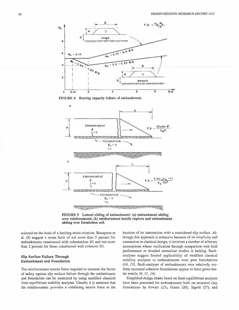
Lateral Embankment Sliding
A simplified analysis to use in calculating the factor of safety against failure due to lateral embankment sliding is shown in Figure 5. The important reinforcement properties for design against sliding are the soil reinforcement interface friction or adhesion characteristics, determined from direct shear tests and a limiting reinforcement tensile force per unit width, T (in kN/ m); in Figure 1, A.1 tan <!>' is the embankment fill-reinforcement interface friction, and A.z is the reinforcement-foundation interface adhesion. To control embankment cracking, T is usually
30 TRANSPORTATION RESEARCH RECORD 1153
8 -~ F.S . I' H
E-z -r "\
8 D I rough
=i?(\iJIA't""".17.t:r Ji'\£ 4$\t -Jri<JJ<CJ-.•
6
4
2
0 0.61 2 4 6 8 B IO
FIGURE 4 Bearing capacity failure of embankment.
Q,
~~~~~~~~~~--.
EMBANKMENT
ti' c'• O
r
"'--- FOUNDATION
l'lu • 0 Cu
b
bA1 Ian 11 · KaH
-b .
H
EMBANKMENT
l!' c'• 0 'Y
--- FOUNDATION 0u - 0 Cu
~~~A"Vff.W/JWA'%.~~
FIGURE S Lateral sliding of embankment: (a) embankment sliding over reinforcement; (b) reinforcement tensile rupture and embankment sliding over foundation soil.
selected on the basis of a limiting strain criterion. Bonaparte et al. (8) suggest a strain limit of not more than 5 percent for embankments constructed with cohesionless fill and not more than 2 percent for those constructed with cohesive fill.
Slip Surface Failure Through Embankment and Foundation
The reinforcement tensile force required to increase the factor of safety against slip surface failure through the embankment and foundation can be estimated by using modified classical limit equilibrium stability analyses. Usually it is assumed that the reinforcement prnvides a stabilizing tensile force at the
location of its intersection with a considered slip surface. Although this approach is attractive because of its simplicity and connection to classical design, it involves a number of arbitrary assumptions whose verification through comparison with field performance or detailed numerical studies is lacking. Backanalyses suggest limited applicability of modified classical stability analyses to embankments over peat foundations (14, 15). Back-analyses of embankments over relatively uniform saturated cohesive foundations appear to have given better results (6, 11, 16).
Simplified design charts based on limit equilibrium analyses have been presented for embankments built on saturated clay foundations by Fowler (25), Gourc (26), Ingold (27), and
Bonaparte and Christopher
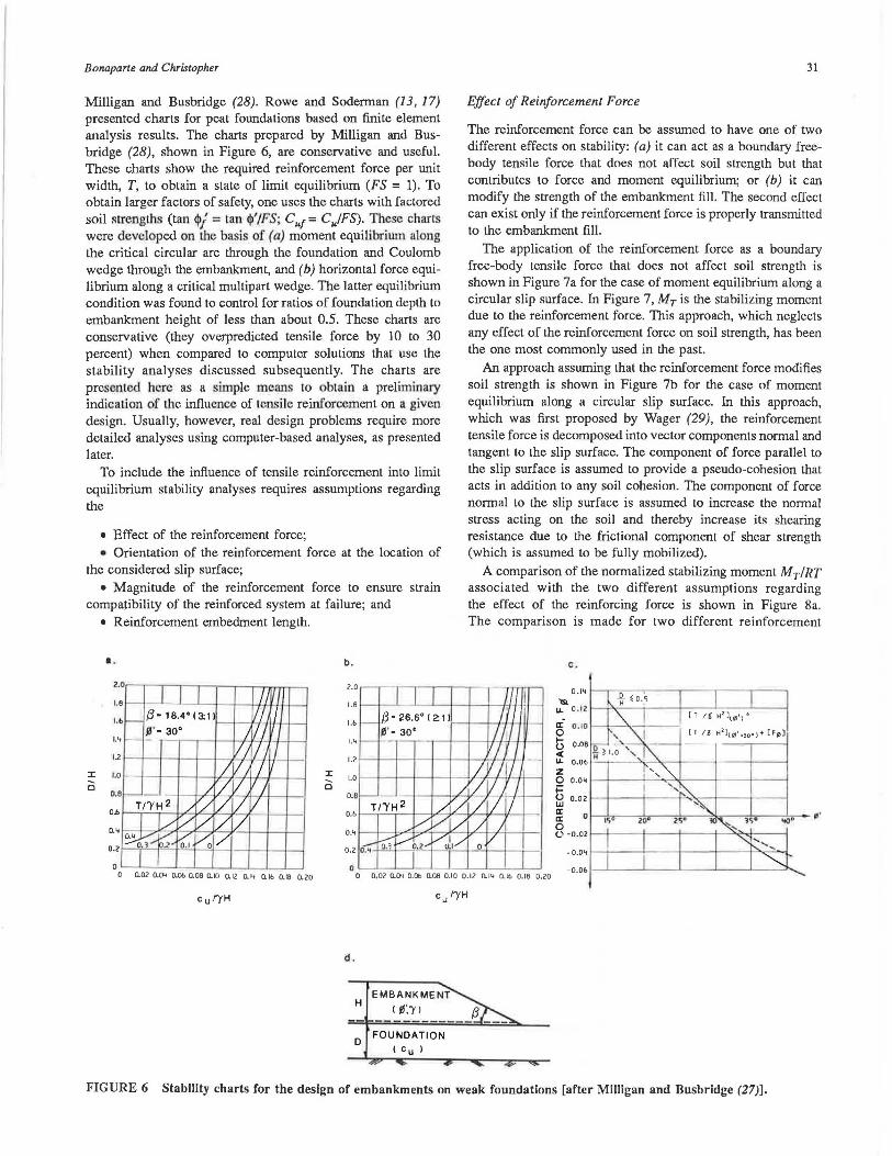
Milligan and Busbridge (28). Rowe and Soderman (13, 17) presented charts for peat foundations based on finite element analysis results. The charts prepared by Milligan and Busbridge (28), shown in Figure 6, are conservative and useful. These charts show the required reinforcement force per unit width, T, to obtain a state of limit equilibrium (FS = 1). To obtain larger factors of safety, one uses the charts with factored soil strengths (tan $/ = can $'IFS; Cu/= CufFS). These charts were developed on lhe basis of (a) moment equilibriwn along the critical circular arc through the foundation and Coulomb wedge through the embankment, and (b) horizontal force equilibrium along a critical multipart wedge. The latter equilibrium condition was found to control for ratios of foundation depth to embankment height of less than about 0.5. These charts are conservative (they overpredicted tensile force by 10 to 30 percent) when compared to computer solutions that use the stability analyses discussed subsequently. The charts are presented here as a simple means to obtain a preliminary indication of the influence of tensile reinforcement on a given design. Usually, however, real design problems require more detailed analyses using computer-based analyses, as presented later.
To include the influence of tensile reinforcement into limit equilibrium stability analyses requires assumptions regarding the
• Effect of the reinforcement force; • Orientation of the reinforcement force at the location of
the considered slip surface; • Magnitude of the reinforcement force to ensure strain
compatibility of the reinforced system at failure; and • Reinforcement embedment length.
.. b .
2.0
1.e
l. b /3· 18.4°(3:1)
s·- 30• 1.4
12
:I: 1.0 :I:
c c
31
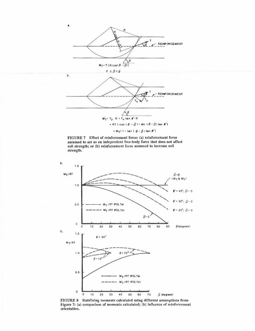
Effect of Reinforcement Force
The reinforcement force can be assumed to have one of two different effects on stability: (a) it can act as a boundary freebody tensile force that does not affect soil strength but that contributes to force and moment equilibrium; or (b) it can modify the strength of the embankment fill. The second effect can exist only if the reinforcement force is properly transmitted to the embankment fill .
The application of the reinforcement force as a boundary free-body tensile force that does not affect soil strength is shown in Figure 7a for the case of moment equilibrium along a circular slip surface. In Figure 7, MT is the stabilizing moment due to the reinforcement force. This approach, which neglects any effect of the reinforcement force on soil strength, has been the one most commonly used in the past.
An approach assuming that the reinforcement force modifies soil strength is shown in Figure 7b for the case of moment equilibrium along a circular slip surface. In this approach, which was first proposed by Wager (29), the reinforcement tensile force is decomposed into vector components normal and tangent to the slip surface. The component of force parallel to the slip surface is assumed to provide a pseudo-cohesion that acts in addition to any soil cohesion. The component of force normal to the slip surface is assumed to increase the normal stress acting on the soil and thereby increase its shearing resistance due to the frictional component of shear strength (which is assumed to be fully mobilized).
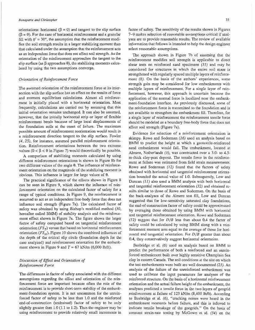
A comparison of the normalized stabilizing moment MT/RT associated with the two different assumptions regarding the effect of the reinforcing force is shown in Figure 8a. The comparison is made for two different reinforcement
c .
0 .14 1-,-;;----.---..--------.--.----. ;:- 0 . 12 \--~-:..:.~ -~-0+' : _ _ +-_ __L _ __JL..__~
[T/~H2 )(~'>" a: 0. 10 ~-1---'>.·~--o [1 / ~ H 2 l[ ~'.w ) + [F~] lJ o.oe
0 --'-,·--'ll. ---1--~ --~-_..,
:t. O.Ob ii ) l.O '
z 0 0 .04 l-4----+---'"-.--><----1---1----" ~ lil 0.02 1-+---l----l"-.::-.--l---I---~
~ 0 1'\'.--- 2=±07"• --=-!,.--~>h---..,...., __ t..,,__ • •
0 t.' -0 .02 t--t---1---r---1-~~t---!
0.02 O.C>< O.Ob 0.06 0.10 0 .12 O.'" O. lb 0.16 0.20
d .
H
D FOUNDATION ( Cu )
FIGURE 6 Stability charts for the design of embankments on weak foundations [after Milligan and Busbridge (27)].
a.
b.
..
b.
Mr· T· [ R cos ((j -/Jl I
0 <; ~ <. (}
M~· Tp R •Tn tan Jl'·R
T __ c::_ ~~l~ORCEMENT
- RT [cos ( (} -fJl+ •In <8-{3lt11n 11'1
- Mr I 1 + tan < 8 - (3 >tan .fl'' I
FIGURE 7 Effect of reinforcement force: (a) reinforcement force assumed to act as an independent free-body force that does not affect soil strength; or (b) reinforcement force assumed to increase soil strength.
1.5
Mr/RT
1.0
0.5
0 0
1.5
Mr/RT
, .0
0 .5
0
----------_,..,- -- ........... ,,.,-"' .---- .......... ....... ___ --..... ........ .........
.;;::::.------ .........
MT /RT <FIG.7al
----- Mr /RT <FIG.7bl
10 20 30 40 50 60 70
II'· 30°
-----
Mr/RT (FIG.7al
Mr /RT (FIG.7bl
If· 40°; {3· o
~· - 30°;(3 - o
If - 20°; (3 = o
80 90 (}!degrees I
0 1 O 20 30 40 50 60 70 (3 lde~eesl
FIGURE 8 Stabilizing moments calculated using different assumptions from Figure 7: (a) comparison of moments calculated; (b) inHuence of reinforcement orientation.
Bonapar/e and Christopher
orientations: horizontal (~ = 0) and tangent to the slip surface (~ = 0). For the case of horizontal reinforcement and a granular fill with <l>' = 30°, the assumption that the reinforcement modifies the soil strength results in a larger stabilizing moment than that calculated under the assumption that the reinforcement acts as an independent force that does not affect soil strength. As the orientation of the reinforcement approaches the tangent to the slip surface (as ~ approaches 0), the stabilizing moments calculated by using the two assumptions converge.
Orientation of Reinforcement Force
The assumed orientation of the reinforcement force at its intersection with the slip surface has an effect on the results of force and moment equilibrium calculations. Almost all reinforcement is initially placed with a horizontal orientation. Most frequently, calculations are carried out by assuming that this initial orientation remains unchanged. It can also be assumed, however, that the initially horizontal strip or layer of flexible reinforcement bends because of large local displacements of the foundation soils at the onset of failure. The maximum possible amount of reinforcement reorientation would result in a reinforcement direction tangent to the slip surface. Fowler (4, 25), for instance, assumed parallel reinforcement orientation. Reinforcement orientations between the two extreme values (0 < ~ < 0 in Figure 7) would theoretically be possible.
A comparison of stabilizing moments calculated by using different reinforcement orientations is shown in Figure 8b for two different values of the angle e. The influence of reinforcement orientation on the magnitude of the stabilizing moment is obvious. This influence is larger for large values of e.
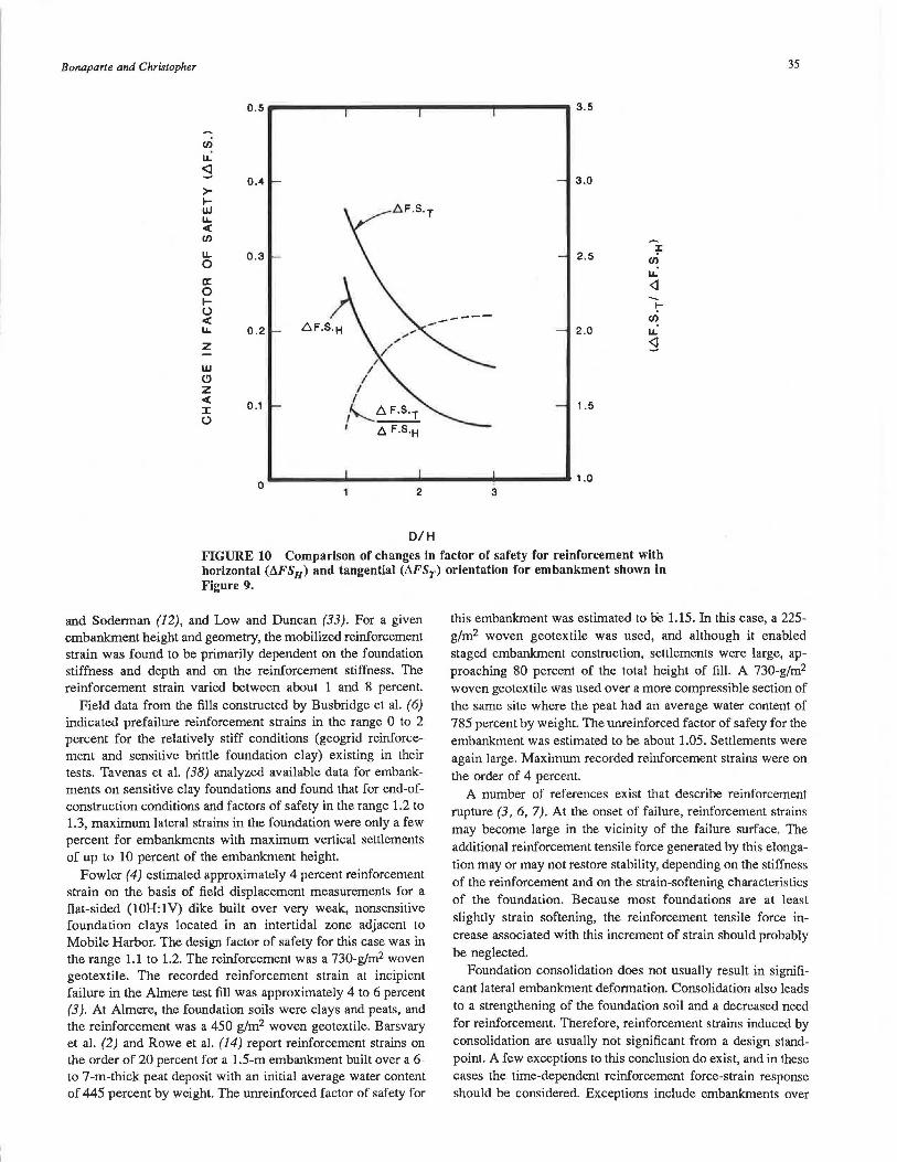
The practical significance of the effects shown in Figure 8 can be seen in Figure 9, which shows the influence of reinforcement orientation on the calculated factor of safety for a range of typical conditions. In Figure 9, the reinforcement is assumed to act as an independent free-body force that does not influence soil strength (Figure 7a). The calculated factor of safety was obtained by using Bishop's modified method (30, hereafter called BMM) of stability analysis and the reinforcement effect shown in Figure 7a. The figure shows the larger factor of safety computed based on tangential reinforcement orientation (FS T) versus that based on horizontal reinforcement orientation (FSu). Figure 10 shows the combined influences of the depth of the critical slip circle (foundation depth for the case analyzed) and reinforcement orientation for the embankment shown in Figure 9 and T = 67 kN/m (6,000 lb/ft).
Discussion of Effect and Orientation of Reinforcement Force
The differences in factor of safety associated with the different assumptions regarding the effect and orientation of the reinforcement force are important because often the role of the reinforcement is to provide short-term stability of the embankment-foundation system. It is not uncommon for the unreinforced factor of safety to be less than 1.0 and the reinforced end-of-construction (undrained) factor of safety to be only slightly greater than 1.0 (1.1 to 1.2). Thus the engineer may be using reinforcement to provide relatively small increments in
33
factor of safety. The sensitivity of the results shown in Figures 7-9 makes selection of reasonable assumptions critical if analyses are to provide reasonable results. The review of available information that follows is intended to help the design engineer select reasonable assumptions.
The approach shown in Figure 7b of assuming that the reinforcement modifies soil strength is applicable to direct shear tests on reinforced sand specimens (31) and may be considered for structures in which the entire soil mass is strengthened with regularly spaced multiple layers of reinforcement (8). On the basis of the authors' experiences, some strength gain may be considered for low embankments with multiple layers of reinforcement. For a single layer of reinforcement, however, this approach is uncertain because the application of the normal force is localized near the embankment-foundation interface. As previously discussed, some of the reinforcement force is transmitted to the foundation and is not available to strengthen the embankment fill. Therefore, for a single layer of reinforcement the reinforcement tensile force should be modeled as a boundary free-body force that does not affect soil strength (Figure 7a).
Evidence for selection of a reinforcement orientation is skimpy. Rowe and Soderman (16) used an analysis based on BMM to predict the height at which a geotextile-reinforced sand embankment would fail. The embankment, located at Almere, Netherlands (3), was constructed over a 3.0- lo 4.5-m-thick clay-peat deposit. The tensile force in the reinforcement at failure was estimated from field strain measurements. Rowe and Soderman (12) found that the factors of safety obtained with horizontal and tangential reinforcement orientation bounded the actual value of 1.0. Subsequently, Low and Duncan (11) also used a BMM analysis with both horizontal and tangential reinforcement orientation (32) and obtained results similar to those of Rowe and Soderman. On the basis of the back-analyses of the Almere test fill, Low and Duncan suggested that for low-sensitivity saturated clay foundations, the end-of-construction factor of safety could be approximated by averaging those obtained by using BMM with horizontal and tangential reinforcement orientation. Rowe and Soderman (12) suggest that for D !B less than about 0.4 the factor of safety could be calculated by using BMM along with a reinforcement moment arm equal to the average of those for horizontal and tangential orientation. For DI B greater than about 0.4, they conservatively suggest horizontal orientation.
Busbridge et al. (6) used an analysis based on BMM to predict the performance of both a reinforced and an unreinforced embankment built over highly sensitive Champlain Sea clay in eastern Canada. The soil conditions at the site on which the test embankments were built are well documented (23). An analysis of the failure of the unreinforced embankment was used to calibrate the input parameters for analyses of the reinforced structure. On the basis of a horizontal reinforcement orientation and the actual failure height of the embankment, the analyses predicted a tensile force in the two layers of geogrid reinforcement at failure of 123 kN/m (8,400 lb/ft). According to Busbridge et al. (6), "cracking noises were heard in the embankment moments before failure, and this is inferred to indicate tensile breakage of the geogrids." On the basis of constant strain-rate testing by McGown et al. (34) on the

34 TRANSPORTATION RESEARCH RECORD 1153
EMBANKMENT J'- 35', 'Y· 18.8kN/m3I120pcfl
FOUNDATION
>.... UJ
"" < I/)
"" 0 a: 0 t5 < ""
1.3
1.2
1.1
1.0
0.9
D (VARIABLE!
" D/H - 1.0~//
" " /.
" /
" /
/ , "~ /
/ /
/ " " "
Cu• 12kPa (250 plfl
lu - O
/
" / /
/
HORIZONTAL
TANGENTIAL
0 29 58 87 116 ( kNlml ( 20001 ( 40001 ( 60001 ( 80001 (lb/ft)
REINFORCEMENT FORCE , T
FIGURE 9 Influence of assumed reinforcement orientation on calculated factor of safety for typical embankment reinforcement application.
geogrid product used in the field trials, the range of possible break loads for two layers of reinforcement are estimated to be 110 to 140 kN/m (7,500 to 9,600 lb/ft). Using the same location and radius of the critical circle found by Busbridge et al. (6), and a tangential reinforcement orientation, the authors calculated a reinforcement force at a factor of safety of 1.0 equal to approximately 60 kN/m (4,100 lb/ft), which is too low. On the basis of this result, for brittle, strain-sensitive foundations, a horizontal reinforcement orientation would appear to be appropriate.
Reinforcement Tensile Force at Failure
Selection of a limiting value of reinforcement tensile force is a key step preceding stability calculations. The magnitude of this force should depend on the deformation at failure of the embankment-foundation system and on the force-elongation behavior of the reinforcement, including reinforcement creep. Determination of the force-elongation relationship for geotextile and geogrid reinforcement is discussed in detail elsewhere (8, 18, 35, 36). Reinforcement elongation due to deformation of the embankment-foundation system is discussed next.
In an embankment application, reinforcement elongation may be induced as a result of the following (8):
• Placement of reinforcement and establishment of construction working pad;
• Undrained constant-volume distortion of the foundation soil during and after embankment construction;
• Localized embankment deformations associated with the development of a slip surface at the onset of failure; and
• Settlement due to consolidation of the foundation soil.
For relatively stiff reinforcement [secant tensile stiffnesses of at least 250 kN/m (17,000 lb/ft) at a strain of 2 percent], strains due to reinforcement placement and establishment of a construction working pad would be expected to be small, certainly not more than 1 or 2 percent. These small strains are in contrast to the large strains that have been observed when lightweight nonwoven geotextiles have been used with foundation displacement construction methods. The latter construction alternative is not considered here.
The tensile strain in reinforcement due to undrained constant-volume distortion has been investigated by using nonlinear finite element analyses by Boutrup and Holtz (37), Rowe
Bonaparte and Christopher 35
0.5 3.5
Cf)
u.: <l
0.4 3.0 >-~ w LL < Cf)
LL 0.3 2.5 ~ 0 Cf)
u.: a: <l 0 ~ -(.)
I-
< ---- Cf)
LL 0.2 .6F.S.H ,, ... 2.0 u.: z " " ~ /
w / I
(!) I z I < 0.1
I J: ~l:;.F.S.T 1 .5 (.) I ---,
.6. F.S.H
0 ._ _____________ .,.. ____ • 1.0
2 3
D/H FIGURE 10 Comparison of changes in factor of safety for reinforcement with horizontal (t:.FSn) and tangential (t:.FSr) orientation for embankment shown in Figure 9.
and Soderman (12), and Low and Duncan (33). For a given embankment height and geometry, the mobilized reinforcement strain was found to be primarily dependent on the foundation stiffness and depth and on the reinforcement stiffness. The reinforcement strain varied between about 1 and 8 percent.
Field data from the fills constructed by Busbridge et al. (6) indicated prefailure reinforcement strains in the range 0 to 2 percent for the relatively stiff conditions (geogrid reinforcement and sensitive brittle foundation clay) existing in their tests. Tavenas et al. (38) analyzed available data for embankments on sensitive clay foundations and found that for end-ofconstruction conditions and factors of safety in the range 1.2 to 1.3, maximum lateral strains in the foundation were only a few percent for embankments with maximum vertical settlements of up to 10 percent of the embankment height.
Fowler (4) estimated approximately 4 percent reinforcement strain on the basis of field displacement measurements for a flat-sided (lOH:lV) dike built over very weak, nonsensitive foundation clays located in an intertidal zone adjacent to Mobile Harbor. The design factor of safety for this case was in the range 1.1to1.2. The reinforcement was a 730-g!m2 woven geotextile. The recorded reinforcement strain at incipient failure in the Almere test fill was approximately 4 to 6 percent (3 ). At Almere, the foundation soils were clays and peats, and the reinforcement was a 450 g/m2 woven geotextile. Barsvary et al. (2) and Rowe et al. (14) report reinforcement strains on the order of 20 percent for a 1.5-m embankment built over a 6-to 7-m-thick peat deposit with an initial average water content of 445 percent by weight. The unreinforced factor of safety for
this embankment was estimated to be 1.15. In this case, a 225-g/m2 woven geotextile was used, and although it enabled staged embankment construction, settlements were large, approaching 80 percent of the total height of fill. A 730-g/m2 woven geotextile was used over a more compressible section of the same site where the peat had an average water content of 785 percent by weight. The unreinforced factor of safety for the embankment was estimated to be about 1.05. Settlements were again large. Maximum recorded reinforcement strains were on the order of 4 percent.
A number of references exist that describe reinforcement rupture (3, 6, 7). At the onset of failure, reinforcement strains may become large in the vicinity of the failure surface. The additional reinforcement tensile force generated by this elongation may or may not restore stability, depending on the stiffness of the reinforcement and on the strain-softening characteristics of the foundation. Because most foundations are at least slightly strain softening, the reinforcement tensile force increase associated with this increment of strain should probably be neglected.
Foundation consolidation does not usually result in significant lateral embankment deformation. Consolidation also leads to a strengthening of the foundation soil and a decreased need for reinforcement. Therefore, reinforcement strains induced by consolidation are usually not significant from a design standpoint. A few exceptions to this conclusion do exist, and in these cases the time-dependent reinforcement force-strain response should be considered. Exceptions include embankments over

36
peat bogs or other deposits with nonuniform thicknesses that may result in large localized reinforcement strains.
On the basis of this discussion and review of available information for highly sensitive, brittle clay foundations, the reinforcement tensile force for design against slip surface foundation failure should be based on a limiting strain of not more than 2 to 3 percent. Limiting strains of not more than 4 to 6 percent should be considered for medium- to low-sensitivity clay foundations. If the foundation soils are nonsensitive and plastic, the reinforcing force should be based on limiting strains of not more than 10 percent.
Two additional factors that should be considered in selecting a reinforcement tensile force for design are (a) the strain to limit lateral embankment deformations to an acceptable level, and (b) the strain to limit creep rupture of the reinforcement. The first factor may be important if cohesive embankment fills are used. In this case, the primary benefit of reinforcement may be to prevent embankment cracking (11). To prevent cracking, mobilized reinforcement strains should be small, as noted in the previous discussion. The second factor may become important if the anticipated reinforcement strains are larger than the strain that would result in reinforcement creep.
Reinforcement Embedment Length
The previous discussion was concerned with selection of a maximum reinforcement force under the embankment. This maximum force can only be generated if the reinforcement has adequate embedment beyond the failure surface. The embedment length required to mobilize a given reinforcement tensile force is dependent on the embankment-reinforcement bond, the foundation-reinforcement bond, or both, as well as on the embankment overburden pressure. For most new embankment construction, embedment length requirements are automatically satisfied by spanning the reinforcement from toe to toe. A length check should be made, however, for embankmentwidening or embankment-raising projects when reinforcement lengths are limited, when the reinforcement does not span the entire embankment, or when very stiff [K greater than about 1,000 kN/m (68,000 lb/ft)] reinforcement is used.
An embedded geotextile or geogrid resists pullout through friction and adhesion on its upper and lower surfaces, and by passive resistance developed by elements perpendicular to the direction of reinforcement. Average interface friction and adhesion coefficients can be defined from the results of direct shear or pullout tests for geotextiles and pullout tests for geogrids. These average coefficients take into account both soil reinforcement friction and adhesion, as well as the passive resistances of regularly spaced, repetitive, perpendicular elements (8). Interface parameters should be measured with soils representative of the embankment fill and the foundation, with test configurations as close as possible to conditions in the field.
Once the interface parameters have been defined, a profile of available reinforcement force (22) can be developed for any given embankment cross section. The available reinforcement force will be the lesser of the force available based on an embedment length analysis and the limit reinforcement tensile force based on the embankment deformation evaluation described in the last section. Near the edge of the embankment, reinforcement pullout or sliding will controi the maximum
TRANSPORTATION RESEARCH RECORD 1153
available force. Under the center of the embankment, the limit reinforcement tensile force will control.
Longitudinal Reinforcement Force
The preceding discussion was directed solely at reinforcement forces and strains in the direction perpendicular to the embankment centerline. Reinforcement forces and strains can also be developed parallel to the embankment centerline. The potential for longitudinal reinforcement forces and strains may occur (a) during construction over very weak sites prone to mud waving; (b) at the ends of an embankment; and (c) owing to differential settlements and bending of embankments built over nonuniform foundation conditions. Barsvary et al. (2) measured reinforcement strains on the order of 8 percent under an embankment built over a peat bog that had variable depth. When these conditions prevail, longitudinal reinforcement forces and strains should be considered during design.
Other Factors
The discussion has focused on reinforcement aspects of limit equilibrium analyses of reinforced embankments. It should be remembered that other factors affect the stability of unreinforced and reinforced embankments alike. The geotechnical literature relating to unreinforced embankment stability should be consulted to evaluate these other factors, which include (a) foundation strength details, including the presence of a crust, strength changes with depth, or thin seams of silts and fine sands; (b) embankment fill properties, including undrained embankment cohesion; (c) embankment cracking, which may be reduced in a reinforced embankment compared to an unreinforced embankment; (d) progressive failure effects; and (e) time-dependent foundation changes, including creep and consolidation.
CONSTRUCTION OF EMBANKMENTS OVER WEAK FOUNDATIONS
Selection and implementation of appropriate construction procedures is of critical importance for reinforced embankments over weak foundations, for at least two reasons: (a) a potential exists for embankment failure during construction if construction sequencing and procedures are not carefully planned; and (b) because often only one layer of reinforcement is used, improper installation- or construction-related material damage could result in embankment failure because there is no redundancy in the reinforcement system.
Site Access and Construction Equipment
Procedures to prevent failures into very weak foundations during construction have been mostly concerned with the placement of woven geotextiles (4, 18, 39) because these were the first synthetic reinforcing materials used in this application. Light construction equipment is recommended so as not to disturb the ground surface (which might consist of a desiccated crust or vegetative mat) or, worse, induce bearing capacity failure of the foundation. Haliburton et al. (40) and Fowler (4)
Bonaparte and Christopher
reported that small, wide-tracked dozers with maximum ground pressures on the order of 17 kPa (2.5 psi) are suitable for spreading as little as 0.3 m (1 ft) of sand fill over geotextiles resting on saturated cohesive foundation soils with undrained shear strengths in the range of approximately 2 to 7 kPa (50 to 150 lb/ft2). During the early stages of construction, haul roads for delivering embankment fill may require special design. Alternatively, partially loaded dump trucks can be used. Design criteria for reinforced haul roads were summarized by Christopher and Holtz (18).
Site Preparation
Site preparation generally depends on the strength of the foundations soil and the presence of a desiccated crust or vegetative mat. As previously noted, care should be taken not to disrupt any crust or mat covering the site. Site preparation must be compatible with the survivability (ability to survive the construction process with minimum damage) and workability (ease of placement, sewing, joining, etc.) characteristics of the reinforcing material. Christopher and Holtz ( 18) provide guidelines for geotextile selection on the basis of survivability and workability criteria that depend on subgrade conditions, construction equipment, and type of cover or backfill material.
[A different approach to reinforcement survivability has been used by geogrid manufacturers. They have recommended reducing a product's reinforcement force for design by a site damage factor that accounts for possible material damage resulting from the construction operation (8, 11). These factors are determined from tension tests on product specimens that have been subjected to field installation placement and fill compaction procedures.]
On sites that can support light construction equipment, a thin granular working table is often constructed before placement of the reinforcement. If the foundation cannot support construction equipment, geotextile reinforcement will usually be placed directly on the subgrade. With geogrid reinforcement, a lightweight geotextile separator is often placed on the subgrade, and the reinforcement is then placed on top of the separator, either before or after the first soil lift. The geotextile separator is usually ignored in stability calculations. Occasionally a lightweight (100 to 150 g/m2) geotextile separator will be used to facilitate construction of a working pad before placement of heavyweight (typically 500 to 1,000 g/m2) geotextile reinforcement. This procedure finds use when stumps and pointed brush that cannot be removed owing to site conditions might diminish the performance of the reinforcement (18). With peat foundations, Rowe et al. (15) suggest placement of the reinforcement directly on the root mat.
Reinforcement Placement Procedures
Placement procedures for geotextiles have been reviewed in a number of references (4, 18, 21, 39). All recommend that geotextile seams be sewn and not overlapped. Ideally, sewn seams should be as strong as the geotextile itself. Practically, seam strengths rarely exceed two-thirds of the geotextile strength, even with high strength thread and double sewn overlap seams (18). Seam strengths must meet reinforcement design strength requirements as the seam strength represents the minimum
37
strength or weak link of the reinforcement system. Lock-stitching has been recommended to preclude seam unraveling. Polypropylene, polyester, polyamide (nylon), and polyaramide (Kevlar) threads are used. To avoid the risk of overstressing seams, geotextiles are usually unrolled with their machine direction perpendicular to the centerline of the embankment. Field labor can be minimized by prefabricating multiwidth geotextile panels at the manufacturing plant or in a staging area.
Geogrid placement procedures differ somewhat from those used for geotextiles. Geogrid rolls tend to be smaller than geotextile rolls, and wind does not hinder placement. Overlapping procedures depend on geogrid type. Geogrid products that are strong in one direction only (uniaxial) are unrolled perpendicular to the embankment centerline, and adjacent strips are usually butted. No mechanical connection is used between strips except for occasional metal hog rings or stakes to hold the grid alignment during fill placement. This procedure works well when plane strain conditions prevail and when a good working pad is available. Otherwise, a second layer of uniaxial grid will be required, oriented parallel to the embankment centerline.
Geogrid products that are strong in two directions (biaxial) may be unrolled parallel or perpendicular to the embankment centerline. If the open area of the grid is large (greater than 60 to 70 percent) and its aperture size permits anchorage by the fill material, adjacent rolls can be overlapped without mechanical connection. Overlap widths should be based on pullout test results. For applications that require mechanical connections, polymer dowel bars, braid, and metal hog rings have been used to form the connections. All of these mechanical connection procedures are relatively labor-intensive. Connection strengths of 80 to 90 percent of the material strength can be achieved. Connection strengths must meet reinforcement design strength requirements. Often a combination of geogrid overlap and mechanical connection is used, and the connection strength is assumed equal to the geogrid strength.
Fill Placement Procedures
It is important that the reinforcement be placed without wrinkles or folds to allow mobilization of the reinforcement tensile force with a minimum amount of deformation. During fill placement, it may be necessary to pull wrinkles or folds out of the reinforcement manually to keep it taut. Hog rings, steel pins, and stakes can be used to hold geogrids in place during fill spreading. For sites that can support construction equipment [with undrained shear strengths greater than about 15 kPa (300 lb/ft2)], Christopher and Holtz (18) suggest that fill be pushed from the center of the embankment forward and out towards the edges of the embankment. This is sometimes called the inverted-U fill placement procedure because of the shape of the front edge of the fill in plan view.
Fill placement procedures become critical for sites underlain by foundation soils with undrained shear strengths Jess than about 10 kPa (200 lb/ft2) if construction related failures are to be avoided. Fill placement procedures for very weak inorganic clays were developed by Haliburton and have been described in detail in a number of references ( 4, 18, 21, 40 ). They consist of building access roads and starter embankments along the longitudinal edges of the main embankment to pretension the reinforcement. Interior fill sections are placed after the reinforcement is pretensioned. In this way, fill placement proceeds in a
38
U shape that is just the opposite of the procedure prescribed for stronger sites. A mud wave will typically form inside the U. Fill dumping, spreading, and initial lift thickness need to be carefully managed during placement of the initial layer of fill to avoid localized bearing capacity failures. The lift thickness for the first lift should be the minimum required to support construction traffic and can be based on haul road design procedures.
SUMMARY
The goal of this paper is to give the design engineer an understanding of the ways in which geotextile and geogrid reinforcement improve the performance of embankments over weak foundations and to provide practical guidance in the use of limit equilibrium analyses for design. To achieve the latter goal, the available literature was reviewed and coupled with the authors' personal experiences. The literature review indicated that modified classical limit equilibrium procedures may be used to evaluate the end-of-construction factor of safety of embankments over saturated clay foundations. The procedures appear to be less reliable in predicting performance over peat deposits, however. Further, it was suggested that the reinforcement force be included as a boundary free-body force in the equilibrium calculations. Guidance was provided on the appropriate direction and magnitude of the reinforcement force to use in calculations. The reinforcement force magnitude was largely dependent on the deformation of the embankment foundation system at failure. Reinforcement strains induced by these deformations are in the range of 1 to 10 percent. Construction procedures that have been successfully used in the past were also reviewed.
ACKNOWLEDGMENTS
This paper was written while the first author was employed by the Tensar Corporation, Morrow, Ga. Its support is gratefully acknowledged. The authors also would like to thank G. R. Schmertmann and J. P. Giroud for reviewing a draft of the paper. Special thanks are due to Barbara Hutcheson and Doris Campbell, who typed the paper, and to Rick Komada, who drafted the figures.
REFERENCES
1. J. Fowler, J. Peters, and L. Franks. Influence of Reinforcement Modulus on Design and Construction of Mohicanville Dike No. 2. Proc., Third International Coriference on Geotextiles, Vienna, Vol. 1, 1986, pp. 267-271.
2. A. K. Barsvary, M. D. Macl..ean, and C. B. H. Cragg. Instrumented Case Histories of Fabric Reinforced Embankments Over Peat Deposits. Proc., Second International Conference on Geotextiles, Las Vegas, Nev., Vol. 3, 1982, pp. 647--652.
3. J. Brackel, M. Coppins, A. C. Maagdenberg, and P. Risseeuw. Stability of Slopes Constructed with Polyester Reinforcing Fabric, Test Section at Almere-Holland. Proc., Second International Conference on Geotextiles, Las Vegas, Nev., Vol. 3, 1982, pp. 727-732.
4. J. Fowler. Design, Construction, and Analysis of Fabric-Reinforced Embankment Test Section at Pinto-Pass, Mobile, Alabama. Technical Report EL-81-8, Waterways Experiment Station, U.S. Army Corps of Engineers, Vicksburg, Miss., 1981.
TRANSPORTATION RESEARCH RECORD 1153
5. J. Hannon. Fabric Support Embankment Over Bay Mud. Proc., Second International Conference on Geotextiles, Las Vegas, Nev., Vol. 3, 1982, pp. 653-658.
6. J. R. Busbridge, P. Chan, V. Milligan, P. R. LaRochelle, and L. D. Lefebvre. The Effect of Geogrid Reinforcement on the Stability of Embankments on a Soft Sensitive Champlain Clay Deposit. Report to Canadian Transportation Development Center, Golder Associates, and Ontario and Universite Laval, Quebec, March 1985.
7. J. E. Fluet, B. R. Christopher, and A. R. Slaters. Geosynthetic Stress-Strain Response Under Embankment Loading Conditions. Proc., Third International Conference on Geotextiles, Vienna, Vol. 1, 1986, pp. 175-180.
8. R. Bonaparte, R. D. Holtz, and J. P. Giroud. Soil Reinforcement Design Using Geotextiles and Geogrids. ASTM Symposium Geotexlile Testing and the Design Engineer, Los Angeles, Calif., July 1985.
9. J. P. Giroud. Designing with Geotextiles. Materiaux et Constructions, Vol. 14, No. 82, 1981, pp. 257-272.
10. T. C. Kinney. Tensile Reinforcement of Road Embankments on Polygonal Ground by Geolextiles and Related Materials. Interim Report to State of Alaska, Department of Transportation and Public Facilities, Fairbanks, Alaska, March 1986.
11. B. K. Lew and J. M. Duncan. Analysis of the Behavior of Reinforced Embankments on Weak Foundations. Report VPI/CEGT-85-11, Virginia Polytechnic Institute, Blacksburg, October 1985.
12. R. K. Rowe and K. L. Soderman. An Approximate Method for Estimating the Stability of Geotextile Reinforced Embankments. Canadian Geotechnical Journal, Vol. 22, No. 3, 1985, pp. 392-398.
13. R. K. Rowe. Reinforced Embankments: Analysis and Design. Journal of Geolechnical Engineering Division, ASCE, Vol. 110, No. GT2, 1984, pp. 231-246.
14. R. K. Rowe, M. D. MacLean, and A. K. Barsvary. The Observed Behavior of a Geotextile-Reinforced Embankment Constructed on Peat. Canadian Geotechnical Journal, Vol. 21, No. 2, 1984, pp. 289-304.
15. R. K. Rowe, M. D. MacLean, and K. L. Soderman. Analysis of a Geotextile-Reinforced Embankment Constructed on Peat. Canadian Geotechnical Journal, Vol. 21, No. 3, 1984, pp. 563-576.
16. R. K. Rowe and K. L. Soderman. Comparison of Predicted and Observed Behavior of Two Test Embankments. Geolextiles and Geomembranes, Vol. 1, No. 2, 1984, pp. 143-160.
17. R. K. Rowe and K. L. Soderman. Geotextile Reinforcement of Embankments on Peat Geotextiles and Geomembranes, Vol. 2, No. 4, 1985, pp. 277-298.
i8. B. R. Christopher and R. D. Holtz. Geotextile Engineering Manual. FHWA, U.S. Department of Transportation, 1985.
19. V. Milligan and P. LaRochelle. Design Methods for Embankment Over Weak Soils. Proc., Symposium on Polymer Grid Reinforcement in Civil Engineering, Institution of Civil Engineers, London, 1984, pp. 95-102.
20. K. Terzaghi and R. B. Peck. Soil Mechanics in Engineering Practice, John Wiley and Sons, New York, 1967.
21. J. Fowler and T. A. Haliburton. Design and Construction of Fabric Reinforced Embankments. The Use of Geolextiles for Soil Improvements, Preprint 80-177, ASCE Convention, Portland, Oreg., 1980, pp. 89- 1J8.
22. R. A. Jewell. A Limil Equilibrium Design Method for Reinforced Embankments on Soft Foundations. Proc., Second International Conference on Geolextiles, Las Vegas, Nev., Vol. 3, 1982, pp. 671- 676.
23. J. Mandel and J. Salencon. Force portante d'un sol sur une assise rigide. Proc., Seventh International Conference on Soil Mechanics and Foundation Engineering, Mexico City, Vol. 2, 1969, pp. 157- 164.
24. J. Mandel and J. Salencon. Force portante d'un sol sur assise rigide: Etude theorique. Geotechnique, Vol. 22, No. 1, 1967, pp. 79-93.
25. J. Fowler. Theoretical Design Considerations for Fabric-Reinforced Embankments. Proc., Second International Conference on Geotextiles, Las Vegas, Nev., 1982, pp. 665--670.
Bonaparte and Christopher
26. J. P. Gourc. Quelques Aspects du Comportement des Geotextiles en Mecanique des Sols. Ph.D. thesis. University of Grenoble, Grenoble, France, 1982.
27. T. S. Ingold. An Analytical Study of Geotextile Reinforced Embankments. Proc., Second International Conference on Geotextiles, Las Vegas, Nev., Vol. 3, 1982, pp. 683-688.
28. V. Milligan and J. R. Busbridge. Guidelines for the Use ofTensar Geogrids in Reinforcement of Fills Over Weak Foundations. Golder Associates Report to the Tensar Corporation, Mississauga, Ontario, 1983.
29. 0. Wager. Building of a Site Road Over a Bog at Kilanda, Alvsborg County, Sweden. Report to the Swedish State Power Board, Boras, Sweden, 1981.
30. A. W. Bishop. The Use of the Slip Surface in the Stability Analysis of Slopes. Geotechnique, Vol. 5, No. 1, 1955, pp. 7-17.
31. R. A. Jewell. Some Effects of Reinforcement on the Mechanical Behavior of Soil. Ph.D. thesis, University of Cambridge, Cambridge, U.K., 1980.
32. J. M. Duncan, B. K. Low, and V. R. Schafer. STABGM: A Computer Program for Slope Stability Analysis of Reinforced Embankments and Slopes. Geotechnical Engineering Report, Virginia Polytechnic Institute, Blacksburg, September 1985.
33. P. LaRochelle, B. Trak, F. Tavenas, and M. Roy. Failure of a Test Embankment on a Sensitive Champlain Clay Deposit. Canadian Geotechnical Journal, Vol. 11, No. 1, 1974.
39
34. A. McGown, K. Z. Andrawes, K. C. Yeo, and D. D. DuBois. The Load-Strain-Time Behavior of Tensas Geogrids. Proc., Symposium on Polymer Grid Reinforcement in Civil Engineering, Institution of Civil Engineers, London, 1984, pp. 11-17.
35. R. A. Jewell. Material Properties for the Design of Geotextile Reinforced Slopes. Geote:xJiles and Geomembranes Journal, Vol. 2, No. 2, 1985, pp. 83-109.
36. A. McGown, N. Paine, and D. D. Dubois. Use ofGeogrid Properties in Limit Equilibrium Analysis. Proc., Symposium on Polymer Grid Reinforcement in Civil Engineering, Institution of Civil Engineers, London, 1984, pp. 11-17.
37. E. Boutrup and R. D. Holtz. Analysis of Embankments on Soft Ground Reinforced with Geotextiles. Proc., Eighth European Conference on Soil Mechanics and Foundation Engineering, Helsinki, Vol. 2, 1983, pp. 469-472.
38. F. Tavenas, C. Mieussens, and F. Bourges. Lateral Displacements in Clay Foundations Under Embankments. Canadian Geotechnical Journal, Vol. 16, No. 3, 1979.
39. R. D. Holtz. Soil Reinforcement with Geotextiles. Third NJ'/ International Geotechnical Seminar, Nanyang Technological Institute, Singapore, 1985, pp. 55-74.
40. T. A. Haliburton, J. D. Lawmaster, and V. E. McGuffey. Use of Engineering Fabrics in Transportation Related Applications. FHWA, U.S. Depanment of Transportation, 1982.
Publication of this paper sponsored by Committee on Mechanics of Earth Masses and Layered Systems.


![Dynamic Analysis of Embankments Reinforced with Micro-Pilesanm.yazd.ac.ir/article_836_b8d82e7a41f1440e9a3add35be0a2953.pdf · ABAQUS/CAE ver. 6.13-1[9], and two-dimensional analysis](https://static.fdocuments.in/doc/165x107/5e1c009188bf484e07342a3e/dynamic-analysis-of-embankments-reinforced-with-micro-abaquscae-ver-613-19.jpg)