Design and Construction of an Annular Detonation Initiator
48
Design and Construction of an Annular Detonation Initiator M. Grunthaner, S. I. Jackson, and J. E. Shepherd Graduate Aeronautical Laboratories California Institute of Technology Pasadena, CA 91125 September 28, 2001 GALCIT Report FM:2001.005
Transcript of Design and Construction of an Annular Detonation Initiator
Design and Construction of an Annular Detonation Initiator
M. Grunthaner, S. I. Jackson, and J. E. Shepherd
Graduate Aeronautical Laboratories California Institute of Technology
Pasadena, CA 91125
September 28, 2001
GALCIT Report FM:2001.005

Abstract A device capable of creating a collapsing toroidal detonation wave front has been designed and constructed. The goal is to generate pressures and temperatures at the focal point of the collapsing detonation wave that will be sufficient to initiate detonations in insensitive fuel-air mixtures inside of a detonation tube without blocking the flow path and causing associated losses in propulsive efficiency. The annular initiator uses a single spark and an array of small diameter channels to generate and merge many detonation waves to create a single detonation wave with a toroidal front. The initiator design utilizes shrink fitting as a method to seal the array of channels used in the creation the toroidal front.

Contents 1 Introduction ……………………………………………………………… 1 2 Shrink-fitting ……………………………………………………………… 5 3 Example Calculations ……………………………………………………... 8 4 Making the Parts …………………………………………………………….. 11 5 Assembling the Parts ………………………………………………………16 6 Summary ……………………………………………………………………... 20 A Part and Assembly Drawings …………………………………………….. 23

1
1 Introduction Recently, there has been significant interest in developing methods of initiating detonations in less sensitive fuel-air mixtures (such as JP10 and air, or propane and air) that do not involve high energy input. Such methods are appealing for air-breathing applications since JP10 is a liquid fuel and air is readily available from the atmosphere. One such method involves shock wave focusing. In shock wave focusing, a high-pressure region is generated by a converging wave or the collision of two or more shock waves. In the focal region, high pressures and temperatures occur. In general, increased temperatures and pressures facilitate the initiation of detonation waves. The following describes the development and assembly of a practical design for creating a focal region inside of a detonation tube without blocking the flow path and causing associated losses in propulsive efficiency. The device uses an array of small diameter channels to generate and merge many detonation waves to create a single detonation wave with a toroidal front. A planar version of this device has been successfully built and tested (Jackson et al., 2001) to demonstrate the principles of wave front merging to create a single front. It is anticipated that the imploding toroidal shock wave will be highly effective at initiating detonations with virtually no initiator interference. This device currently has a patent pending (Shepherd and Jackson, 2001). The key advantage of this method is the use of a single point of ignition to produce a planar wave over a large area. An alternate method is to use multiple ignition sources that directly initiate detonation. This is expensive and the timing is not always reliable, resulting in substantial deviations from planarity. Another technique is to use a single point of ignition and an expanding channel; however, the resulting wave front will be curved, which is undesirable. The planar version (Fig. 1) consists of a main channel (1), secondary channels (2), spark igniter (5), obstacles (6) in the main channel, an exit plane (4), and a test volume (7). The channels are all machined into a common metal substrate (3) that is sealed with a cover plate so that the entire assembly forms a pressure vessel. All secondary channels terminate at a common exit plane (4), opening into a test section area (7). The length of the path from the spark igniter to the exit of each secondary channel is the same for all channels. Operation is as follows: The channels and test section are filled with a combustible mixture such as a hydrocarbon fuel and oxygen. Electrical discharge through the igniter (5) starts a flame (deflagration) propagating in the main channel. The deflagration travels along the main channel, encountering the machined obstacles (6). The machined obstacles create turbulence and accelerate the deflagration to a detonation wave. The detonation wave travels along the length of the main channel; at the intersection with each secondary channel, a detonation is started in that secondary channel while, at the same time, continuing to propagate down the main channel. The geometry of the system

2
is such that all detonation waves will encounter the end (at the exit plane) of each secondary channel at the same time. Expanding detonation fronts will emerge (Fig. 2) into the test volume (7). These individual fronts (8) will merge (Fig. 3) to create a planar detonation front (9), which will continue to propagate into the additional volume. To create a toroidal wave, the device was modified such that the exit of each channel lay on a circle, with the channels exhausting inwards. This involved mapping the plane on which the planar design existed to a cylinder. Thus an annular imploding wave is created instead of a linear wave. A sketch of this device is shown in Figure 4. The mapping transforms the metal substrate containing the channels into an inner sleeve while the cover plate becomes the outer sleeve. Creation of a pressure seal between the inner and outer sleeves is accomplished by a shrink-fit. The theory and implementation of this design is now discussed.
3
Figure 1: The planar initiator
Figure 2: Emerging fronts
Figure 3: Merging fronts

4
Figure 4: Annular imploding wave device
5
2 Shrink-fitting The necessary problem of sealing the Inner Sleeve (the Initiator) against the Outer Sleeve was solved with shrink-fitting. Shrink-fitting is generally the process of heating or cooling parts that otherwise would interfere, assembling them, and allowing the temperatures to equilibrate. With the dimensions of the finished Inner Sleeve already set, the final dimensions of the Outer Sleeve would determine the properties of the shrink-fit.
Figure 5 represents a hollow cylinder with inner radius a and outer radius b , the basic geometry for both the Inner Sleeve and Outer Sleeve. To accurately determine the maximum stresses and interface pressures present in the shrink-fit, the necessary stress distributions in a hollow cylinder submitted to uniform pressure on both the inner and outer surfaces must be found. For a cylindrical tube under uniform pressure, the radial and hoop stress
distributions are
( )
( ),1)(
,1)(
22
22
222
22
22
22
222
22
abbpap
rabppba
r
abbpap
rabppba
r
oiio
oiior
−−
+−
−−=
−−
+−
−=
θσ
σ (1)
where op and ip are the uniform outside and inside pressures exerted on the hollow cylinder. For plane stress,
rE υσσε θθ −= (2)
where E is the Young’s Modulus and υ is the Poisson’s Ratio of the material. Thus, the radial displacement u can be found since
.ru=θε (3)
Substituting Equation 3 into Equation 2 and solving for the displacement yields
( ).)()()( rrErru rυσσθ −= (4)
6
In order to solve for the stresses and pressures involved in the shrink-fitting of two hollow cylinders that would otherwise have overlapping dimensions, a few relations must be noted. The radial stress of the inner cylinder at the outer surface must be the same as the radial stress of the outer cylinder at the inner surface (the equilibrium interface pressure intp ). Also, the total radial interference e must be equal to the difference between the outer radius of the inner cylinder and the inner radius of the outer cylinder, and also equal to the total magnitude of radial displacement of each of the cylinders. Letting the subscripts 1 and 2 represent the inner and outer cylinders respectively
int21 )()(21
pab rr == σσ , (5) )()( 112221 buauabe −=−= . (6)
Setting the inside pressure of the inner cylinder and the outside pressure of the outer cylinder equal to zero, the maximum hoop stress of the inner cylinder is
21
21
21int
max,2
1 abbp
−−=θσ . (7)
The maximum hoop stress of the outer cylinder (tensile at the inner surface) is
22
22
22
22
intmax,2 abbap
−+
=θσ . (8)
Solving Equation 6 will allow one to find the interface pressure given the interference, or the interference given the interface pressure. The interface pressure can be solved for more easily, and the solution put in a form suitable for input into a spreadsheet. Thus finding the interference necessary for a given interface pressure or maximum hoop stress constraint is just an iterative process of changing the interference once all other dimensions are fixed. Attention must also be paid to features in the cylinders that may intensify the stresses and thus constrain the maximum allowable interference. The second problem that arises during shrink-fitting is that of actually assembling the interfering parts. This is accomplished via thermal expansion and contraction. For the heating or cooling of a part with reference length 0l with a relatively constant coefficient of thermal expansion α , the resulting change in length is defined as
( ) 00 lTTl −=∆ α . (9)
For small interferences, adequate clearance can be produced by simply cooling the inner cylinder while the outer cylinder remains at room temperature. For an interference e and inner cylinder outer diameter 1b , the necessary change in temperature of the inner cylinder to exactly match the outer cylinder inner diameter is
1beT
α=∆ . (10)

7
Adequate clearance in addition to the interference would be necessary for actually assembling the parts, so a more significant drop in temperature than shown in Equation 10 is preferable.

8
3 Example Calculations The material used for the Inner Sleeve was 3.00 in inner diameter by 4.00 in outer diameter extruded Al 6061-T6 tube stock. After surfacing and polishing the outside to ensure a reliable sealing surface, the final outer diameter was 3.975 in. The material stock used for cutting the Outer Sleeve was 3.50 in inner diameter by 5.50 in outer diameter extruded Al 6061-T6 tube stock. As discussed below, the inner diameter was later increased by honing to 3.971 in. The outer diameter was left at 5.50 in. The first value to be estimated for the shrink-fit is the minimum interface pressure between the two sleeves. As shown in drawing 22, Cut Initiator (Assembly), the Inner Sleeve contains one primary channel and 29 secondary channels that serve as detonation pathways. The peak pressures produced in these detonations can reach 30 bar (equivalent to 435 psi). An effective interface pressure is necessary to keep the two sleeves clamped together during these pressure spikes. Conservatively, assume this peak pressure acts over the entire interface surface rather than just the much smaller total channel area. Using a dynamic load factor of 2, the resulting pressure is
8754352 =× psi. (11)
Equation 6 can now be used to find the required interference to produce this interface pressure
)()( 112221 buauabe −=−= . (6)
Substituting Equation 4 into Equation 6
( ) ( ))()()()( 1111
1222
2
21122
bbEbaa
Eae rr συσσυσ θθ −−−= . (12)
Substituting the proper expressions from Equation 1 for the stresses into Equation 12 and reducing yields
( ) ( )
+
−
−−−
+
−
−−=
1
111
2
22212
12
1
21
21
1
122
22
2
22
22
2
222
oooi
iioi p
ab
bpppaEbp
ab
ppbapEae υυ . (13)
The following substitutions are then made
EEE == 21 , (14) υυυ == 21 , (15)
int21ppp io == , (16) 0
21== oi pp . (17)
9
Equation 13 then reduces to
−
−++
+
−+= υυ 2
12
1
21
21
122
22
22
22
2int
ababb
ababa
Epe . (18)
At this point one can either substitute eba −= 12 to solve for e , or substitute 21 abe −= to solve for 2a . Choosing to solve for e , the final equation becomes
( ) ( )( )
−
−++
+
−−−+−= υυ 2
12
1
21
21
121
22
21
22
1int
ababb
ebbebbeb
Epe . (19)
Besides e , all variables in Equation 19 are known. The following values are then substituted, including the minimum interface pressure found earlier: 875int =p psi, 500.11 =a in, 9875.11 =b in, 75.22 =b in, 33.0=υ ,
71001.1 ⋅=E psi. (20)
With the aid of a solver, the resulting interference is found
0012.0=e in. (21)
Therefore any interference greater than 0.0012 in, or equivalently any outer cylinder inner radius less than 1.9863 in, will satisfy the minimum interface pressure found above. The idealized perfect cylinder diameters are definitely not the case in the real world, and there are likely to be fluctuations of 0.0005 in or more despite the imposed tolerances during machining. Thus, increased interferences are beneficial in this respect. Keeping the maximum hoop stresses below the yield strength and ultimate strength of the material becomes the next design constraint. Substituting the values above into Equations 7 and 8, the maximum hoop stresses in the inner and outer cylinders are 07.4max,1
−=θσ ksi, 78.2max,2
=θσ ksi. (22)
The maximum hoop stress is compressive at the inner surface of the inner cylinder. The yield strength of Al 6061-T6 is 39.9 ksi. At first glance it would appear that the hoop stresses are well below the yield strength. However, since the Inner Sleeve used in the Annular Initiator Assembly is not a simple hollow cylinder, further analysis must be done.

10
The primary channel in the Inner Sleeve is 0.375 in wide and deep. This is an interruption in the otherwise 0.488 inch thick wall. This results in a stress magnification of
30.1375.0488.0 = . (23)
However, there is an additional stress concentration in the square channel’s corners. Assuming an optimistic stress concentration factor of 4, the total stress magnification is
21.5375.0488.04 =× . (24)
The true maximum hoop stress seen is then estimated to be
2.2107.421.5max, =−×=trueθσ ksi. (25)
This is well below the yield strength. A larger interference can thus be chosen. Choosing a convenient interference of 0.002 in, the resulting interface pressure and true maximum hoop stress is calculated to be 49.1int =p psi,
1.36max, =trueθσ ksi. (26)
The true maximum hoop stress is close, but still less than the yield strength. The 0.002 in radial interference was chosen. The problem of cooling the Inner Sleeve adequately to both surpass the 0.002 inch radial interference with the Outer Sleeve and allow enough clearance for insertion during assembly must now be investigated. The chilling method of choice was chosen to be a liquid nitrogen bath at 77 K. The following values are substituted into Equation 9: 51034.2 −×=α K-1, 2980 =T K, 77=T K,
9875.10 =l in. (27)
The Inner Sleeve’s resulting change in radius is
0102.0−=∆l in. (28)
This is significantly larger than the 0.002 in radial interference, allowing 0.0082 in of radial clearance for assembly. The inner radius of the Outer Sleeve can now be honed to its final dimension of 1.9855 in.

11
4 Making the Parts
Inner Sleeve (Initiator) Notes: This part is the annular equivalent of the linear initiator seen in drawing 21, Unwrapped Initiator. Once the tube stock is surfaced, a bolt circle is put on one end for attachment of the Handle Plate for assembly. The next feature to be cut is the radius on the end opposite the bolt circle. See Detail
A in drawing 11, Initiator (Assembly). This is done on a CNC lathe with a steady rest due to the extreme length of the part. The helical channels in this part are then cut entirely on a CNC mill with a 4th axis. A 2-D sketch containing the equivalent tool paths for a planar surface is then “wrapped” around a cylinder with a 4.000 in diameter. These paths include points for the Alignment Pin Slot, along with other radial counterbore cuts that lie along the paths of the channels. See drawing 20, Channel Cut Paths, for the 2-D geometry. In 4th axis mode, the appropriate cutting tools and cut depths are then assigned to their respective paths. Each channel width is cut by an entire tool width to allow the channel to be fully defined by a single path. In theory, these channels could all be cut by importing the SolidWorks part file into the CAD/CAM software. However, the part file was too complex to define tool paths via surface selection in both GibbsCAM and SURFCAM. The above 2-D sketch wrap method was used successfully in GibbsCAM. A slight chamfer (as shown in drawing 11, note 3) should be put on the end of the channel walls to aid in assembly. See drawing 11, Initiator (Assembly), for basic dimensions. See drawing 22, Cut Initiator (Assembly), for rotated views of the finished part. Critical Dimensions: This part acts as the inner piece in a shrink-fit, and thus, the outer surface finish is very important. A minimum surface finish of 16 µin is recommended. This outer surface must have a 0.004 in diameter interference fit with the Outer Sleeve (see drawing 12, Outer Sleeve (Assembly)).
12
Outer Sleeve Notes: Once the outside of the tube stock is surfaced, the concentric inside diameter must be honed to its final dimension. A counterbore is then cut on one end to allow a slip-fit with the Focusing Ring. The Alignment Pin Slot is then cut on the opposite end, along with the stepped Spark Plug and Gas Fill holes (see drawing 7, Hole S (Spark Plug Hole), and drawing 8, Hole G (Gas Fill Hole) for dimensions).
Bolt circles are then put on both ends of the Outer Sleeve to aid in assembly. See drawing 12, Outer Sleeve (Assembly), for dimensions. Critical Dimensions: The honed inner diameter of this piece must be 0.004 in smaller than the final outer diameter of the Initiator, plus or minus 0.0005 in. A minimum surface finish of 8 µin should be specified for the hone. The counterbore for the Focusing Ring should allow a slip-fit (see drawing 5, Focusing Ring for dimensions). Special attention should be paid to the angular and axial separations of the Alignment Pin Slot, Spark Plug Hole, and Gas Fill Hole to ensure an accurate mate with their respective slots in the Initiator after assembly.
Focusing Ring Notes: This part, in conjunction with the radius on the end of the Initiator, is used to deflect the detonation inward to focus at the centerline of the Initiator. The inside surface of this part is cut on a CNC lathe. This surface sits above the curved end of the Initiator to form an annulus of constantly increasing area. The effective angle between these two surfaces is illustrated in Figure 8. Minimizing this angle is necessary to reduce the diffraction of the detonation wave through this region. Due to length restrictions of the initiator, the smallest allowable angle was determined to be
3.5°. See drawing 5, Focusing Ring, for dimensions.

13
Critical Dimensions: The outside diameter of this part is to have a slip-fit with the counterbore in the Outer Sleeve. Its overall length should be no more than the counterbore depth to eliminate any possible protrusion after assembly.
Adapter Ring Notes: This part adapts the new Annular Initiator Assembly to the current test tube. It utilizes a Parker Static O-Ring 2-347 for the face seal between the Adapter Ring and the Outer Sleeve, and a Parker Static O-Ring 2-345 for the gland seal between the Adapter Ring and the outside of the current test tube. See drawing 4, Adapter Ring, for dimensions.
Critical Dimensions: The face seal groove should have a surface finish of 16 µin, and the gland seal a surface finish of 32 µin, to assure proper sealing. The gland seal dimensions are important for proper fitment and sealing over the current test tube. All ¼-20 clearance holes are counterbored to sink the bolt head below the surface, preventing protrusion and interference with the face seal.
End Plate Notes: This part seals the open end of the Annular Initiator Assembly. It uses a Parker Static O-Ring 2-347 for the face seal between the End Plate and the Outer Sleeve. See drawing 9, End Plate, for dimensions. Critical Dimensions: The face seal groove should have a surface finish of 16 µin to assure proper sealing.

14
Alignment Ring Notes: This part is to aid in the alignment of the Initiator during insertion into the Outer Sleeve. It is to be counterbored to slip-fit onto the top of the Outer Sleeve and then held in place via three set-screws. The final inner diameter and taper should be cut at once from the same side on a CNC lathe to assure a smooth and continuous inner surface. The clearance slot for the Alignment Pin is cut last. See drawing 13,
Alignment Ring, for dimensions. Critical Dimensions: The counterbore should be a slip-fit over the Outer Sleeve to prevent too much play and help maintain concentricity between the Alignment Ring and the Outer Sleeve. The base of the clearance slot for the Alignment Pin should continue just past the bottom of the Alignment Pin Slot in the Outer Sleeve.
Alignment Pin Notes: This part is press-fit into the Initiator Alignment Pin Slot to aid in alignment during assembly. See drawing 19, Alignment Pin, for dimensions. Critical Dimensions: The outside diameter of this pin should seat properly in the Alignment Pin Slot in the Outer Sleeve without restriction. This
should be tested before it is press-fit into the Initiator.
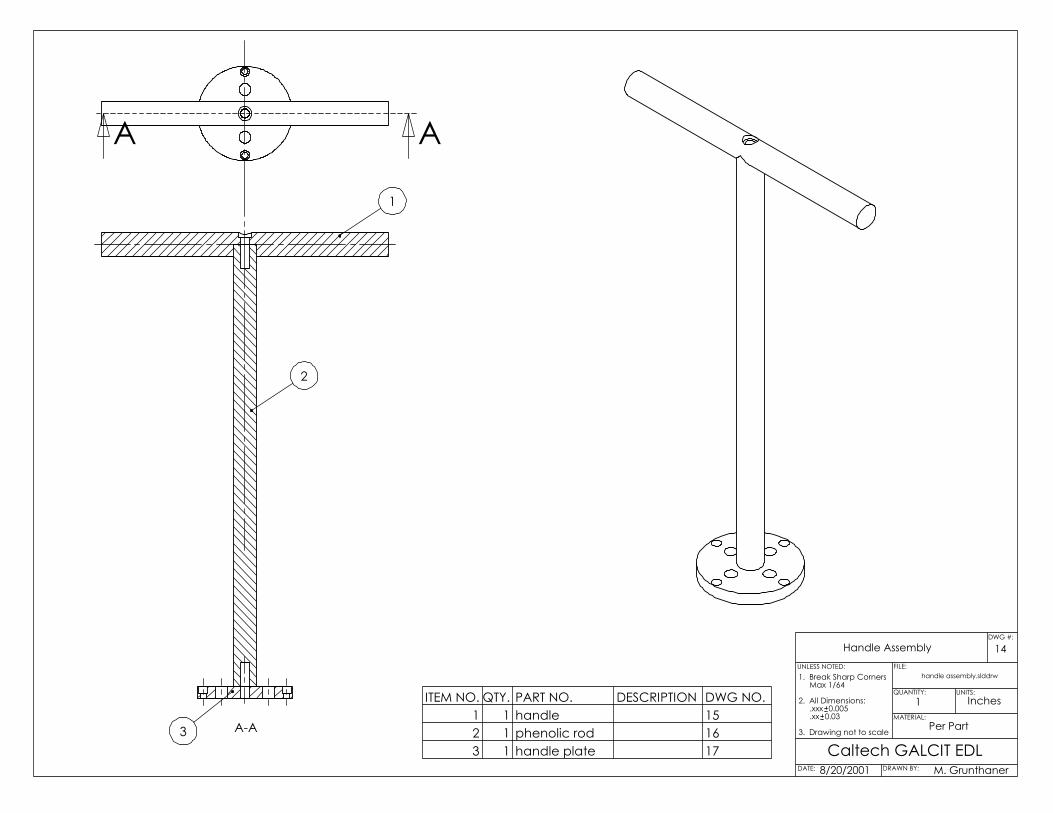
Handle Notes: This is the part that is held during the insertion of the Initiator into the Outer Sleeve. See drawing 15, Handle, for dimensions.

15
Phenolic Rod Notes: This part connects the Handle to the Handle Plate, which is in direct contact with the Initiator and the liquid nitrogen bath before assembly. It is to be made out of phenolic to limit heat transfer between the Handle and the Initiator in the liquid nitrogen bath. See drawing 16, Phenolic Rod, for dimensions. Handle Plate Notes: This part bolts to the top of the Initiator to connect the Handle and Phenolic Rod during assembly. It has four thru-holes to allow nitrogen gas to escape during the insertion of the Initiator into the Outer Sleeve. See drawing 17, Handle Plate, for dimensions. Critical Dimensions: The outer diameter of the Handle Plate
must be slightly less than the outer diameter of the Initiator, and thus less than the inside diameter of the Outer Sleeve, to prevent obstruction during the insertion of the Initiator into the Outer Sleeve.
Assembly Stand Notes: This part is bolted to the base of the Outer Sleeve for assembly. A matching clearanced and counterbored bolt circle should be cut in the center of the part. The outside plate dimensions are not critical. See drawing 18, Assembly Stand, for suggested dimensions. Critical Dimensions: The outer dimensions of the Assembly
Stand should provide stability and support during the assembly process.

16
5 Assembling the Parts
Once all of the parts are machined, the only difficult part of the assembly is inserting the Initiator (Inner Sleeve) into the Outer Sleeve. This is accomplished via a shrink-fit as discussed previously. In preparation for the cooling of the Inner Sleeve, the handle assembly should be constructed. This consists of the Handle, Phenolic Rod, Handle Plate, a washer, and two 3/8-16 UNC socket-cap bolts. They are to be assembled in the manner shown below in Figure 17.
The Pin is then pressed into the Initiator, and the Handle Plate is attached to the Initiator via four 1/4-20 UNC socket-cap bolts as shown in Figure 18.
17
The Outer Sleeve and Alignment Ring should first have their inside surfaces coated with Fluoroglide, a Teflon lubricant, that is still effective at 77 K. The Outer Sleeve should then be attached to the Assembly Stand via 8 1/4-20 UNC socket-cap bolts and the Alignment Ring mounted on the open end as shown below in Figure 19. Care should be taken to ensure that the Alignment Ring is properly seated and concentric with the inner diameter of the Outer Sleeve and its pin slit properly aligned with the alignment pin slot in the Outer Sleeve. The three set-screws located on the outside of the Alignment Ring can be used for fine adjustment.
18
Before cooling the Initiator, it should also be coated in the Teflon lubricant that is still effective at 77 K. The Initiator is then submerged in a liquid nitrogen bath with the handle still accessible. The nitrogen will continue to boil off for a few minutes until the Initiator approaches the 77 K temperature of the liquid. Once the temperatures have equilibrated, the Initiator should be removed from the bath and quickly inserted through the Alignment Ring and into the Outer Sleeve. Care should be taken to mate the Alignment Pin with the alignment pin slot in the Alignment Ring and Outer Sleeve. See Figure 20 below.
Once the parts have equilibrated to room temperature, the parts used for assembly should be removed. The Alignment Pin must first be driven through the assembly before the Alignment Ring can be removed. With the set-screws loosened, the Alignment Ring will

19
slide off and allow access to the Handle Plate bolts. The Handle Assembly and Assembly Plate can then be removed. The permanently connected Inner Sleeve and Outer Sleeve can now be machined to their final dimensions. See drawing 6, Outer Sleeve, for these final dimensions.

20
6 Summary All of the parts were successfully machined to the design specifications. During assembly, the Teflon lubricant and liquid nitrogen cooling allowed the Inner Sleeve to slide effortlessly into the Outer Sleeve. The Annular Initiator Assembly is now waiting to be tested in the GALCIT Explosion Dynamics Laboratory.

21
Acknowledgement This work was supported by the Office of Naval Research Multidisciplinary University Research Initiative, Multidisciplinary Study of Pulse Detonation Engine (Grant 00014-99-0744, subcontract 1686-ONR-0744) and General Electric contract GE-PO-A02 81655. Thanks to Tong-Wa Chao for help with the shrink fit computations, and Joe Haggerty and Brad St. John for CAD/CAM assistance and machining.

22
References Jackson, S.I., J.M. Austin, M. Cooper, E. Wintenberger, J.E. Shepherd, "Development of Initiation Systems for Pulse Detonation Engines," presented at 18th ICDERS meeting, Seattle, 2001 Shepherd, J.E. and S.I. Jackson, "Planar Detonation Initiator," CIT Invention Disclosure: CIT 01-116, 2001

23
Appendix A: Part and Assembly Drawings Drawing 1: Exploded View
Drawing 2: Assembly Drawing
Drawing 3: Initiator
Drawing 4: Adapter Ring
Drawing 5: Focusing Ring
Drawing 6: Outer Sleeve
Drawing 7: Hole S (Spark Plug hole)
Drawing 8: Hole G (Gas Fill hole)
Drawing 9: End Plate
Drawing 10: Assembly Drawing (for assembly)
Drawing 11: Initiator (Assembly)
Drawing 12: Outer Sleeve (Assembly)
Drawing 13: Alignment Ring
Drawing 14: Handle Assembly
Drawing 15: Handle
Drawing 16: Phenolic Rod
Drawing 17: Handle Plate
Drawing 18: Assembly Stand
Drawing 19: Alignment Pin
Drawing 20: Channel Cut Paths
Drawing 21: Unwrapped Initiator
Drawing 22: Cut Initiator (Assembly)
annular initiator (exploded).slddrw
Per Part
Exploded View
8/11/2001
End Plate
O-Ring
Spark Plug Hole
Gas Fill Hole
Outer Sleeve
Initiator
Focusing Ring
O-Ring
1/4-20 Bolts
Adapter Ring
Caltech GALCIT EDL
1
DATE: DRAWN BY:
QUANTITY: UNITS:
MATERIAL:
FILE:UNLESS NOTED:
M. Grunthaner
1 Inches
1. Break Sharp Corners Max 1/64
2. All Dimensions: .xxx 0.005 .xx 0.03
3. Drawing not to scale
DWG #:

A
A
5
4
6
21
Assembly Drawing
annular initiator.slddrw
8/8/2001
Al 6061-T6
Caltech GALCIT EDL
2ITEM NO. QTY. PART NO. DESCRIPTION DWG NO:1 1 Initiator 32 1 Adapter Ring 44 1 End Plate 95 1 Outer Sleeve 66 1 Focusing Ring 5
DATE: DRAWN BY:
QUANTITY: UNITS:
MATERIAL:
FILE:UNLESS NOTED:
M. Grunthaner
1 Inches
1. Break Sharp Corners Max 1/64
2. All Dimensions: .xxx 0.005 .xx 0.03
3. Drawing not to scale
DWG #:

1.00
0
13.0
66
A
1. This dimension to have 0.004" interference fit with outer sleeve inner diameter
2. This chamfer to aid in alignment during assembly
3.600
R1.817
3.975 - 0.0005+0.0005
, Note 1
3.000
0.06
5, N
ote
2
30°
initiator.slddrw
Initiator
Al 6061-T6
8/6/2001
Detail A
Caltech GALCIT EDLDATE: DRAWN BY:
QUANTITY: UNITS:
MATERIAL:
FILE:UNLESS NOTED:
M. Grunthaner
1 Inches
1. Break Sharp Corners Max 1/64
2. All Dimensions: .xxx 0.005 .xx 0.03
3. Drawing not to scale
3DWG #:
A A
0.257 THRU ON A BC 5.050 0.390 0.3008 PLCS
0.257 THRU ON A BC 3.5000.390 FARSIDE 0.300
8 PLCS
5.500
+0.0054.004 0.000
3.000
4.682
4.342 0.000+0.005
B
A-A
0.241
0.28
10.
119
0.10
0
0.50
0
1.00
00.
157
Detail B
Adapter Ring
9/4/2001
adapter ring.slddrw
Al 6061-T6
O-RING GROOVEPARKER STATIC 2-345
O-RING GROOVEPARKER STATIC 2-347
Caltech GALCIT EDL
4
32
16
DATE: DRAWN BY:
QUANTITY: UNITS:
MATERIAL:
FILE:UNLESS NOTED:
M. Grunthaner
1 Inches
1. Break Sharp Corners Max 1/64
2. All Dimensions: .xxx 0.005 .xx 0.03
3. Drawing not to scale
DWG #:

AA
1. This dimension to have slip-fit with corresponding end of outer sleeve
4.200, Note1
4.000
3.000
8/6/2001
Focusing Ring
Al 6061-T6
focusing ring.slddrw
Caltech GALCIT EDL
3.0000.20
0
1.50
0
R2.500
DATE: DRAWN BY:
QUANTITY: UNITS:
MATERIAL:
FILE:UNLESS NOTED:
M. Grunthaner
1 Inches
5DWG #:
1. Break Sharp Corners Max 1/64
2. All Dimensions: .xxx 0.005 .xx 0.03
3. Drawing not to scale

14.7
66
1.70
0
5.500
3.971 - 0.0005+0.0005
, Note 1
4.200, Note 2
0.50
01.
000,
Not
e 4
7/16-20 UNFSee Hole G (DWG #8)
14mm x 1.25See Hole S (DWG #7)
8/6/2001
28.649°
13°
1. This dimension to have 0.004" interference fit with initiator outer diameter
2. This part to have slip-fit with imploder ring outer diameter
3. These threaded holes to be drilled / tapped on both faces of part
4. This depth applies to all tapped holes in part.
1/4-20 UNC 1.000 ON A BC 5.0508 PLCSNote 3
1.50
0
Outer Sleeve
Al6061-T6
outer sleeve.slddrw
Caltech GALCIT EDL
6
DATE: DRAWN BY:
QUANTITY: UNITS:
MATERIAL:
FILE:UNLESS NOTED:
M. Grunthaner
1 Inches
1. Break Sharp Corners Max 1/64
2. All Dimensions: .xxx 0.005 .xx 0.03
3. Drawing not to scale
DWG #:

1.220
0.866
0.561
14mm x 1.25
0.33
1 m
in.
0.40
2 m
ax.
0.04
9 no
m.
120°
0.75
0, N
ote1
Hole S (Spark Plug hole)
8/9/2001
Al6061-T6
spark plug hole.slddrw
7
1. This dimension is the outer sleeve wall thickness.
Champion REJ38 (Short Reach) Spark Plug
Caltech GALCIT EDLDATE: DRAWN BY:
QUANTITY: UNITS:
MATERIAL:
FILE:UNLESS NOTED:
M. Grunthaner
1 Inches
1. Break Sharp Corners Max 1/64
2. All Dimensions: .xxx 0.005 .xx 0.03
3. Drawing not to scale
DWG #:
0.75
0, N
o te
1
0.750
7/16-20 UNF
0.17
5 m
ax.
1. This dimension is the outer sleeve wall thickness.
Hole G (Gas Fill hole)
Al6061-T6
8/9/2001
gas fill hole.slddrw
8
Caltech GALCIT EDLDATE: DRAWN BY:
QUANTITY: UNITS:
MATERIAL:
FILE:UNLESS NOTED:
M. Grunthaner
1 Inches
1. Break Sharp Corners Max 1/64
2. All Dimensions: .xxx 0.005 .xx 0.03
3. Drawing not to scale
DWG #:

5.500
4.682
4.200
A A
0.257 THRU ON A BC 5.0500.390 FARSIDE 0.300
8 PLCS
O-RING GROOVEPARKER STATIC 2-347
1.00
0
0.15
7
A-A
16
End Plate
Al 6061-T6
end ring.slddrw
8/8/2001
Caltech GALCIT EDL
9
DATE: DRAWN BY:
QUANTITY: UNITS:
MATERIAL:
FILE:UNLESS NOTED:
M. Grunthaner
1 Inches
1. Break Sharp Corners Max 1/64
2. All Dimensions: .xxx 0.005 .xx> 0.03
3. Drawing not to scale
DWG #:
A
A
8/29/2001Caltech GALCIT EDL
Assembly Drawing (for assembly)
annular initiator (assembly).slddrw
23
1
Al6061-T6
Excess material is left on both the initiator and outer sleeve for assembly;See "Initiator (Assembly)" and "Outer Sleeve (Assembly)" for dimensions
10
4
ITEM NO. QTY. PART NO. DESCRIPTION DWG NO.1 1 Initiator (Assembly) 112 1 Outer Sleeve (Assembly) 123 1 Alignment Pin 194 1 Alignment Ring 13
DATE: DRAWN BY:
QUANTITY: UNITS:
MATERIAL:
FILE:UNLESS NOTED:
M. Grunthaner
1 Inches
1. Break Sharp Corners Max 1/64
2. All Dimensions: .xxx 0.005 .xx 0.03
3. Drawing not to scale
DWG #:

4 PLCSNote 4
1/4-20 UNF 0.500 ON A BC 3.500
1.00
0
13.0
66
0.37
5
1.00
0
A
AlignmentPin Hole0.500" diam.
1. This dimension to have 0.004" interference fit with outer sleeve inner diameter
2. This excess is for assembly and will be removed after the interference fit; see "Initiator" for final dimensions
3. This chamfer to aid in alignment during assembly
4. This bolt circle for attachment of plate and handle to aid in assembly
5. The channel cuts have been omitted for clarity
Note 2
Note 5
3.600
R1.817
3.975 - 0.0005+0.0005
, Note 1
3.000
0.06
5, N
o te
3
30°
Detail A
initiator (assembly).slddrw
Initiator (Assembly)
Al 6061-T6
8/6/2001Caltech GALCIT EDL
11
DATE: DRAWN BY:
QUANTITY: UNITS:
MATERIAL:
FILE:UNLESS NOTED:
M. Grunthaner
1 Inches
1. Break Sharp Corners Max 1/64
2. All Dimensions: .xxx 0.005 .xx 0.03
3. Drawing not to scale
DWG #:

3.971 - 0.0005+0.0005
, Note 1
0.87
5
4.200, Note 2
1.70
00.
198,
No t
e 330°
15.1
41
5.500
7/16-20 UNFSee Hole G
14mm x 1.25See Hole S
AlignmentPin Slot0.500" diam.
8/6/2001
28.649°
1. This dimension to have 0.004" interference fit with initiator outer diameter and an 8 surface finish
2. This part to have slip-fit with imploder ring outer diameter
3. This is a 30 chamfer with exit 4.100 to aid in alignment during assembly
4. This excess material for assembly. See "Outer Sleeve" for final dimensions
1.87
5
0.37
5
Note 4
Outer Sleeve (Assembly)
Al6061-T6
outer sleeve (assembly).slddrw
Caltech GALCIT EDL
12
DATE: DRAWN BY:
QUANTITY: UNITS:
MATERIAL:
FILE:UNLESS NOTED:
M. Grunthaner
1 Inches
1. Break Sharp Corners Max 1/64
2. All Dimensions: .xxx 0.005 .xx 0.03
3. Drawing not to scale
DWG #:

3 PLCSNote 2
1/4-20 UNC THRU7.
500
30°0.
507
B
B
1. This dimension to have slip-fit with outside diameter of Outer Sleeve
2. These 3 set screws to hold Alignment Ring to Outer Sleeve.
6.500
3.971 -0.0010.000
0.600
4.600
4.015120°
5.500, Note 1
1.00
0
0.50
0
4.00
02.
500
0.90
0
0.36°4.021
Alignment Ring 13
alignment ring.slddrw
Caltech GALCIT EDL8/17/2001
Al 6061-T6
DATE: DRAWN BY:
QUANTITY: UNITS:
MATERIAL:
FILE:UNLESS NOTED:
M. Grunthaner
1 Inches
1. Break Sharp Corners Max 1/64
2. All Dimensions: .xxx 0.005 .xx 0.03
3. Drawing not to scale
DWG #:
A A
A-A
1
2
3
14
Per Part
handle assembly.slddrw
Handle Assembly
Caltech GALCIT EDL8/20/2001
ITEM NO. QTY. PART NO. DESCRIPTION DWG NO.1 1 handle 152 1 phenolic rod 163 1 handle plate 17
DATE: DRAWN BY:
QUANTITY: UNITS:
MATERIAL:
FILE:UNLESS NOTED:
M. Grunthaner
1 Inches
1. Break Sharp Corners Max 1/64
2. All Dimensions: .xxx 0.005 .xx 0.03
3. Drawing not to scale
DWG #:
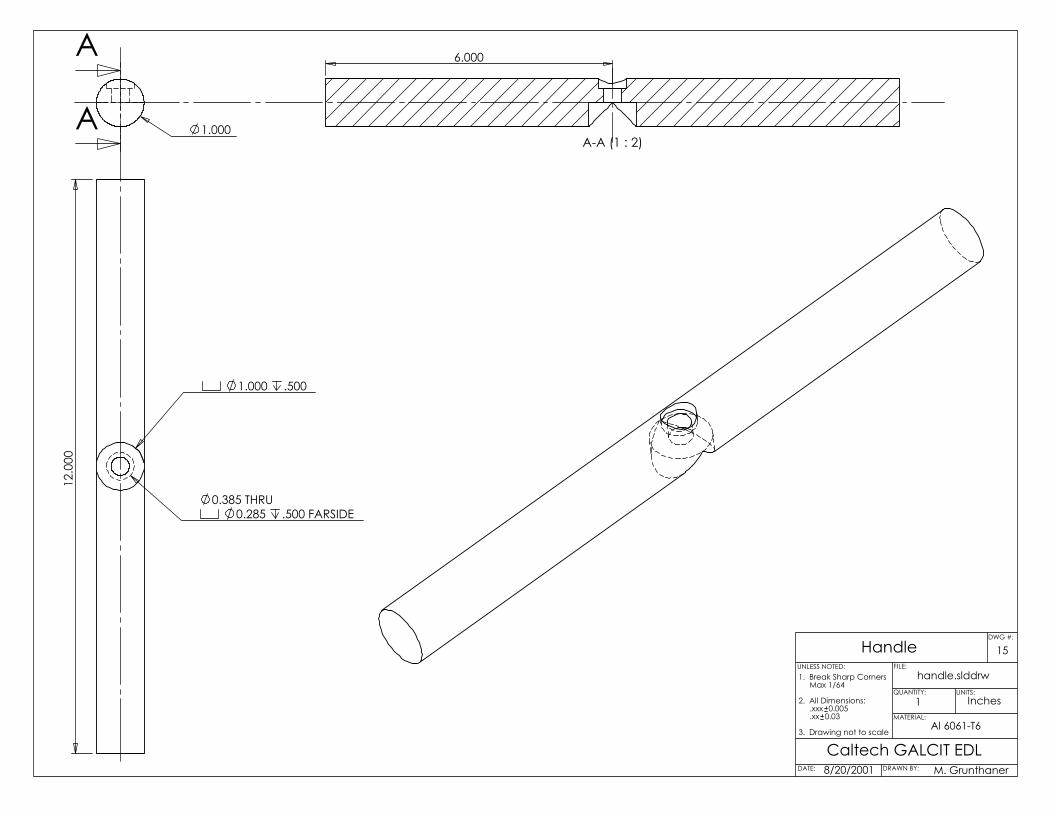
1.000
A
A
0.285 .500 FARSIDE0.385 THRU
1.000 .500
12.0
006.000
A-A (1 : 2)
15
8/20/2001Caltech GALCIT EDL
Al 6061-T6
handle.slddrw
Handle
DATE: DRAWN BY:
QUANTITY: UNITS:
MATERIAL:
FILE:UNLESS NOTED:
M. Grunthaner
1 Inches
1. Break Sharp Corners Max 1/64
2. All Dimensions: .xxx 0.005 .xx 0.03
3. Drawing not to scale
DWG #:
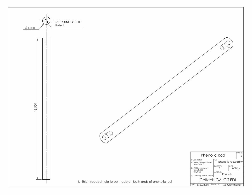
Note 13/8-16 UNC 1.000
1.000
18.5
00
1. This threaded hole to be made on both ends of phenolic rod
16
Caltech GALCIT EDLPhenolic
phenolic rod.slddrw
8/20/2001
Phenolic Rod
DATE: DRAWN BY:
QUANTITY: UNITS:
MATERIAL:
FILE:UNLESS NOTED:
M. Grunthaner
1 Inches
1. Break Sharp Corners Max 1/64
2. All Dimensions: .xxx 0.005 .xx 0.03
3. Drawing not to scale
DWG #:
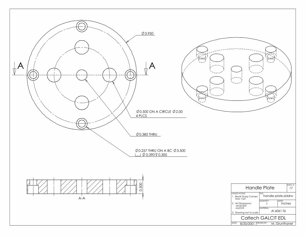
0.257 THRU ON A BC 3.5000.390 0.300
4 PLCS0.500 ON A CIRCLE 2.00
3.950
0.385 THRU
A A
0.50
0
A-A
Handle Platehandle plate.slddrw
Al 6061-T6
Caltech GALCIT EDL8/20/2001
17
DATE: DRAWN BY:
QUANTITY: UNITS:
MATERIAL:
FILE:UNLESS NOTED:
M. Grunthaner
1 Inches
1. Break Sharp Corners Max 1/64
2. All Dimensions: .xxx 0.005 .xx 0.03
3. Drawing not to scale
DWG #:
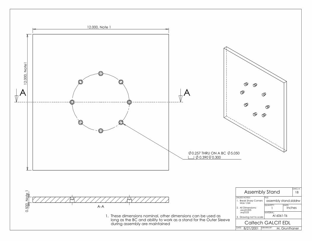
12.000, Note 112
.000
, Not
e1
0.257 THRU ON A BC 5.0500.390 0.300
AA
0.50
0, N
ote
1
A-A
1. These dimensions nominal, other dimensions can be used as long as the BC and ability to work as a stand for the Outer Sleeve during assembly are maintained
18
Caltech GALCIT EDL8/21/2001
assembly stand.slddrw
Al 6061-T6
Assembly Stand
DATE: DRAWN BY:
QUANTITY: UNITS:
MATERIAL:
FILE:UNLESS NOTED:
M. Grunthaner
1 Inches
1. Break Sharp Corners Max 1/64
2. All Dimensions: .xxx 0.005 .xx 0.03
3. Drawing not to scale
DWG #:

0.500, Note 1
2.00
1. This dimension to have a press-fit with Alignment Pin Hole in "Initiator (Assembly)". See "Assembly Drawing (for assembly)" for configuration.
Al 6061-T6
8/29/2001
Caltech GALCIT EDL
alignment pin.slddrw
19Alignment Pin
DATE: DRAWN BY:
QUANTITY: UNITS:
MATERIAL:
FILE:UNLESS NOTED:
M. Grunthaner
1 Inches
1. Break Sharp Corners Max 1/64
2. All Dimensions: .xxx 0.005 .xx 0.03
3. Drawing not to scale
DWG #:

0.99
50.
354
6.28
81.
687
0.41
4
12.566, Note 8
0.20
9
90°
0.87
50.
630
15.0
66
45°
1.27
0
Note 1
Note 2 Note 3 Note 4 Main Channel, Note 5
Seco
nda
ry C
hann
els,
Not
e 6
1. Alignment pin slot, 0.500 0.375
2. Gas Fill hole clearance, 0.500 0.375
3. Spark Plug hole clearance, 0.500 0.375
4. Turbulence counterbores, 0.500 0.375, Main Channel to be cut 1/4" wide and deep in this region
5. Main Channel, 3/8" wide and deep
6. Secondary Channels, 13/64" wide and deep
7. End of Main Channel
8. 4.000 cylinder circumference, "unwrapped"
8/21/2001
Caltech GALCIT EDL
channel cut paths.slddrw
20Channel Cut Paths
Note 7
DATE: DRAWN BY:
QUANTITY: UNITS:
MATERIAL:
FILE:UNLESS NOTED:
M. Grunthaner
1 Inches
1. Break Sharp Corners Max 1/64
2. All Dimensions: .xxx 0.005 .xx 0.03
3. Drawing not to scale
DWG #:

21
Caltech GALCIT EDL8/26/2001
unwrapped initiator.slddrw
Al 6061-T6
Unwrapped Initiator
DATE: DRAWN BY:
QUANTITY: UNITS:
MATERIAL:
FILE:UNLESS NOTED:
M. Grunthaner
1 Inches
1. Break Sharp Corners Max 1/64
2. All Dimensions: .xxx 0.005 .xx 0.03
3. Drawing not to scale
DWG #:

Al 6061-T6
8/29/2001Caltech GALCIT EDL
cut initiator (assembly).slddrw
22Cut Initiator (Assembly)
DATE: DRAWN BY:
QUANTITY: UNITS:
MATERIAL:
FILE:UNLESS NOTED:
M. Grunthaner
1 Inches
1. Break Sharp Corners Max 1/64
2. All Dimensions: .xxx 0.005 .xx 0.03
3. Drawing not to scale
DWG #: