Design and Construction of a 30-Metre-High Glazing Wall ... · PDF filedivided into a...
10
STR-1135-1 3 rd International Structural Specialty Conference 3 ième conférence internationale spécialisée sur le génie des structures Edmonton, Alberta June 6-9, 2012 / 6 au 9 juin 2012 Design and Construction of a 30-Metre-High Glazing Wall Supported by Cable Trusses Georg Josi 1 , Jim Montgomery 1 , Jeff DiBattista 1 , Gord Anderson 1 , Dejan Erdevicki 2 1 DIALOG, Edmonton, Canada (EOR) 2 Erdevicki Structural Engineering, Vancouver, Canada (DDE) Abstract: With a footprint of approximately 7 000 m 2 , the Edmonton Clinic South comprises one basement level and seven floors above ground, plus a two-storey mechanical penthouse. The main architectural feature of the Edmonton Clinic South is a curving, eight-storey glazed atrium wall on its east elevation. The atrium wall is 37 metres high and has a 60 metre arc length, divided into a two-storey curtain wall portion from the ground to the third floor and a clamped point-supported glazing wall portion from the third floor to the roof. The point-supported glass panels span vertically between square HSS girts. In turn, the girts are supported by round HSS356 columns that carry the atrium roof and act as the compression member of a double- cable truss system. The geometry of both cables approximates a parabola. The trusses are spaced at 7.8 m and span from the top of a curved horizontal arch-truss to the roof, a height of almost 30 metres. This paper explains the structural behaviour of the atrium wall cable truss system and how the individual components interact. Challenges encountered during design, fabrication, and erection are outlined. Particular focus is put on the three-dimensional aspects of the design, including stability considerations. The paper also addresses the significance of a constructive collaboration between all parties that led to the successful completion of this new Edmonton landmark, being to the authors' knowledge the largest of its kind in Canada. 1. Introduction In 2004, Alberta Health Services (then called Capital Health in the Edmonton region) developed a vision statement to provide Albertans with "a leading, state-of-the-art enabler of integrated, patient centered clinic care, education and research" (AHS 2006). Based upon the expectations of the vision statement, a partnership between Alberta Health Services, the University of Alberta and the Government of Alberta initiated the construction of two new complementary clinics in the heart of the Health Sciences Campus of the University of Alberta: The Edmonton Clinic Health Academy and the Edmonton Clinic South. The Health Academy primarily houses health sciences academic offices and classrooms, while the Edmonton Clinic South is designed for the professional treatment of outpatients while providing educational opportunities for health sciences students. The focus of this paper, the Edmonton Clinic South, has a footprint of approximately 7000 m 2 , comprising of one basement level and seven floors above ground plus a two-storey penthouse, for a total floor area of 60 000 m 2 . The majority of the structure consists of two-way concrete slabs with drop panels, typically spanning 9.6 m in both directions. The penthouse roof is a steel structure. Concrete shear walls resist the lateral loads. The exterior wall cladding is a combination of lightweight curtain wall and precast concrete panels. One of the main architectural features of
Transcript of Design and Construction of a 30-Metre-High Glazing Wall ... · PDF filedivided into a...

STR-1135-1
3rd International Structural Specialty Conference 3ième conférence internationale spécialisée sur le génie des structures
Edmonton, Alberta
June 6-9, 2012 / 6 au 9 juin 2012
Design and Construction of a 30-Metre-High Glazing Wall Supported by Cable Trusses
Georg Josi1, Jim Montgomery1, Jeff DiBattista1, Gord Anderson1, Dejan Erdevicki2 1 DIALOG, Edmonton, Canada (EOR) 2 Erdevicki Structural Engineering, Vancouver, Canada (DDE)
Abstract: With a footprint of approximately 7 000 m2, the Edmonton Clinic South comprises one basement level and seven floors above ground, plus a two-storey mechanical penthouse. The main architectural feature of the Edmonton Clinic South is a curving, eight-storey glazed atrium wall on its east elevation. The atrium wall is 37 metres high and has a 60 metre arc length, divided into a two-storey curtain wall portion from the ground to the third floor and a clamped point-supported glazing wall portion from the third floor to the roof. The point-supported glass panels span vertically between square HSS girts. In turn, the girts are supported by round HSS356 columns that carry the atrium roof and act as the compression member of a double-cable truss system. The geometry of both cables approximates a parabola. The trusses are spaced at 7.8 m and span from the top of a curved horizontal arch-truss to the roof, a height of almost 30 metres. This paper explains the structural behaviour of the atrium wall cable truss system and how the individual components interact. Challenges encountered during design, fabrication, and erection are outlined. Particular focus is put on the three-dimensional aspects of the design, including stability considerations. The paper also addresses the significance of a constructive collaboration between all parties that led to the successful completion of this new Edmonton landmark, being to the authors' knowledge the largest of its kind in Canada.
1. Introduction
In 2004, Alberta Health Services (then called Capital Health in the Edmonton region) developed a vision statement to provide Albertans with "a leading, state-of-the-art enabler of integrated, patient centered clinic care, education and research" (AHS 2006). Based upon the expectations of the vision statement, a partnership between Alberta Health Services, the University of Alberta and the Government of Alberta initiated the construction of two new complementary clinics in the heart of the Health Sciences Campus of the University of Alberta: The Edmonton Clinic Health Academy and the Edmonton Clinic South. The Health Academy primarily houses health sciences academic offices and classrooms, while the Edmonton Clinic South is designed for the professional treatment of outpatients while providing educational opportunities for health sciences students.
The focus of this paper, the Edmonton Clinic South, has a footprint of approximately 7000 m2, comprising of one basement level and seven floors above ground plus a two-storey penthouse, for a total floor area of 60 000 m2. The majority of the structure consists of two-way concrete slabs with drop panels, typically spanning 9.6 m in both directions. The penthouse roof is a steel structure. Concrete shear walls resist the lateral loads. The exterior wall cladding is a combination of lightweight curtain wall and precast concrete panels. One of the main architectural features of
STR-1135-2
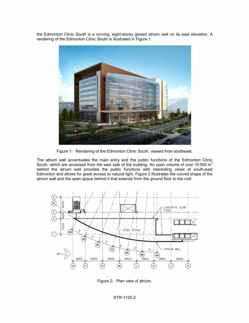
the Edmonton Clinic South is a curving, eight-storey glazed atrium wall on its east elevation. A rendering of the Edmonton Clinic South is illustrated in Figure 1.
Figure 1: Rendering of the Edmonton Clinic South, viewed from southeast.
The atrium wall accentuates the main entry and the public functions of the Edmonton Clinic South, which are accessed from the east side of the building. An open volume of over 10000 m3 behind the atrium wall provides the public functions with interesting views of south-east Edmonton and allows for great access to natural light. Figure 2 illustrates the curved shape of the atrium wall and the open space behind it that extends from the ground floor to the roof.
Figure 2: Plan view of atrium.

STR-1135-3
The curved atrium wall is 37 m high, has an arc length of 60 m, and a radius of 89.4 m. To create the open atrium space, the wall spans from the third level (where an exterior canopy acts as a horizontal wall support) to the roof, a height of nearly 30 m. From the ground floor to the third level, a conventional curtain wall system is used. Above the third floor, clamped point-supported glazing spans between curved HSS203x203 girts with a vertical spacing of 2.2 m. In turn, the girts are supported at every 7.8 m by round HSS356 columns that carry the atrium roof and act as the compression member of a double-cable truss system.
2. The Vision: From Architectural Idea to Design Concept
In the conceptual design stage, the structural and architectural teams held a number of design charrettes to select a structural system to support the glazing system for the atrium wall. The objective was to develop a system that is light and airy in appearance, integrating the mechanical systems that are used to provide heating and cooling to the atrium space.
Cable truss systems are often used to support feature glazing walls for buildings. Typically, these systems span two or three floor levels, with the cables anchored at the top and bottom by relatively rigid structural members. The architectural team was inspired by the appearance of these systems. The structural engineering team conducted an extensive literature review, but was unable to identify any references on a cable truss system of the size and complexity planned for the Edmonton Clinic South atrium wall.
The structural team used the procedures presented by Irvine (1981) on cable trusses for roof systems to develop a conceptual design for the cladding support system. Figure 3 illustrates an initial conceptual sketch of bow shaped trusses that have vertical chords constructed from continuous pretensioned cables. The cables ideally follow a parabolic shape, are anchored at the top and bottom and have horizontal spacers (spreader posts). The spreader posts extend to the columns that support the roof and glazing at the edge of the atrium. In addition to roof vertical loads and lateral wind loads on the glazing, the columns transfer the anchor forces between the ends of the cable trusses, introducing compression into the columns.
Under lateral wind loads, the tension in one of the vertical cables increases while the tension in the other cable decreases. In order to avoid loss of effective flexural stiffness of the system, both cables should be pretensioned so that neither cable goes slack under service load combinations. However, excessive pretensioning forces must be avoided as it is expensive to resist large anchor forces at the ends of the cable trusses and it is often difficult to jack the cables to achieve large pretensioning forces. Thus the selection of an appropriate initial cable pretensioning force is a critical aspect of the design process.
For architectural reasons, minimizing the dimensions of the columns at the edge of the atrium roof was also a design objective. Since the deflections of well proportioned cable trusses under load are relatively small, the team decided that the cable trusses could, in addition to resisting wind loads, be used to brace the 30-metre-tall atrium columns in the direction parallel to the plane of the trusses. Wind girts brace the columns in the direction perpendicular to the plane of the cable trusses.
Consideration was also given to column stability effects if one of the cables did go slack under bending, potentially requiring the cables to be braced out-of-plane to maintain the lateral stability of the trusses (Lew & Scarangello 1997). As discussed in the sections below, it was determined from three dimensional computer simulations and model studies that only relatively light bracing is required to maintain the lateral stability under all design load cases.
In addition to the ultimate and serviceability limit states defined in the Alberta Building Code (ABC 2006), the cable truss system should also be designed with redundancy so that it will not collapse under the effects of service loads even if there is the loss of a single cable.

STR-1135-4
The conceptual design for the cable truss system was passed along to the construction manager for the Edmonton Clinic South to obtain budget pricing. Because of the unique nature of the design, the cost estimates from sub-trades by the construction manager varied widely, and some of the sub-trades indicated that the proposed cable truss system was not viable. Nevertheless, after some deliberation, the project team concluded that it was appropriate to proceed with the design of the cable truss system.
Figure 3: Conceptual design sketch of cable truss system.
3. Three-dimensional Idealizations: Analysis and Design of the Steel Frame Structure and the Cable Truss System
The concept study of the cable trusses considered a simplified planar model, assuming no horizontal or vertical movements of the supports and no out-of-plane contribution of other structural elements. However, a more sophisticated structural model is required to account for horizontal and vertical flexibility of the top and bottom cable supports, for arching action of the curved girt system, and for lateral flexibility of the horizontal supports at the top and bottom of the cable trusses. Consideration must also be given to the out-of-plane behaviour of the cable truss system.
3.1 Cable Anchorage Conditions – Vertical
The vertical anchorage conditions at the top and bottom of the cable trusses, for both the windward and the leeward cables, must be considered in order to assess their effects on cable truss behaviour. As illustrated in Figure 4a, the bottom of the windward cable is connected to the circular HSS356 column, which in turn is supported on a circular cast-in-place concrete column with a diameter of 660 mm. Since this is a stiff support in the vertical direction, it is appropriate to neglect the vertical movement of the bottom windward anchorage in the structural model.

STR-1135-5
The bottom of the leeward cable is anchored to a steel beam, initially designed by the structural engineer of record (EOR) as a W310. The beam cantilevers from a circular HSS127 tie-down column. Obviously, it would be preferable structurally to eliminate the beam cantilever and to use a stiffer tie-down column, but architectural requirements constrained the geometry. In combination, the flexural deflections of the cantilever and the moderate axial stiffness of the tie-down column allowed the leeward cable to undergo vertical movements exceeding 10 mm under factored load. These anchorage movements noticeably affect the cable forces, as expected. The top of the windward cable is anchored to a distributing beam, which is in turn connected to a roof beam. Because the working point of the windward cable is very close to the connection of the roof beam to the HSS356 column, the only significant vertical movements of this anchorage result from axial strain in the column.
The top of the leeward cable is anchored to the same distributing beam. However, the working point of the leeward cable is supported at about the quarter point of the roof beam, contributing significantly to the bending moment in the roof beam. Consequently, vertical deflection of the roof beam must be considered to obtain accurate analysis of the leeward cable forces.
Figure 4: a) Cable truss elevation; b) Horizontal truss at level 3 canopy.

STR-1135-6
3.2 Cable Anchorage Conditions – Horizontal
Flexibility in the horizontal plane of the structures that anchor the cables trusses at the top and bottom must also be considered, as this flexibility influences the force distribution in the cables and girts significantly. At the top cable support locations, the horizontal supports are provided by the roof beams, which shorten or lengthen under wind loading.
At the bottom of the cable trusses, horizontal support is provided by a curved horizontal truss that is integrated into the third level canopy, as shown in Figure 4b. Because of its long span length—about 60 metres—flexibility of the horizontal truss affects the force distribution between the cables and the girts and must be taken into account appropriately in the structural analysis.
Before discussing further the effects of horizontal flexibility of the supports at the cable anchorages, it is instructive to consider the role that the curved HSS254x254 girts play in the overall behaviour of the system. The girts serve not only to support the glazing, they are also essential for stabilizing the cable truss columns in the out-of-plane direction. To provide this stabilization, the girts are connected to the columns to control lateral column displacements. In turn, the girts are anchored into the concrete structure at each end, so that the girt forms a shallow arch with a length of approximately 60 metres. Under wind loading, the atrium glazing wall moves in- and outward. This movement is impeded by the arching action of the girts, which consequently work together with the cable trusses to resist horizontal loads.
Revisiting the horizontal anchorage supports of the cable trusses at the top and the bottom, it becomes evident that the more flexible these supports are, the greater the contribution of the girts in resisting the horizontal loads. The three-dimensional model, constructed using SAP2000 version 14 (CSI 2009) showed that the horizontal movements at the top and bottom cable anchorages had to be limited to less than 5 mm at ultimate limit states in order not to overload the girts. At the top cable anchorages, a WWF1200 section was chosen as roof beam. This beam has reserve strength for the ultimate loads, but provides the required stiffness for the cable supports. At the bottom cable anchorages, the curved shape of the horizontal truss at the third level provides arching action, allowing it to be constructed as a relatively light and shallow truss made of W310 chords and diagonals.
3.3 Participation of Girt Arches
As compared to the simplified planar model developed during concept design, the three-dimensional model of the system exhibits an overall response of the cable truss system in which the cable forces are reduced by over 30% at ultimate limit states. Similarly, horizontal deflections of the cable trusses are reduced to less than half under serviceability loads.
With the significant participation of the girts in the resistance of lateral loads, large axial forces are developed, making necessary the use of HSS203x203 members with wall thicknesses of up to 13 mm. Complicating the system further, architectural requirements constrained the permissible geometry of the girts such that complex connection details were required to introduce the girt forces into the concrete structure.
3.4 Selection of Cable Pretension
The selection of appropriate pretensioning stresses in the cables was made challenging by the EOR's desire to limit the anchorage forces carried by the supporting structure. In order to prevent fluttering of cables during service conditions, the pretension force was selected so that both cables remain in tension for loads smaller than 115% of the service wind load. Under ultimate limit state wind loads, one of the cables of the truss system would go slack, such that all horizontal loads would be carried by the other cable and the girts. Once this condition is reached, the effective stiffness of the system is reduced by approximately 50% for subsequent deflections.

STR-1135-7
The EOR's design of the cable truss system, using non-linear geometric analyses, resulted in stainless steel cables with a diameter of 40 mm. To provide lateral stability for the vertical cables, a system of horizontal bracing cables 20 mm in diameter was specified at each storey.
4. Proprietary System Components: Integrating the Delegated Design Engineer
Architecturally exposed cable truss systems are often one-of-a-kind prototypes in which the clevises, cable anchorages, and other components are proprietary products. In order to provide open competition amongst qualified contractors, certain aspects of the cable truss system could not be specified in detail during the design phase of the project. The participation of a delegated design professional engineer (DDE) retained by the contractor for the cable truss system was also necessary. That DDE was responsible for the detailed design of the truss system and the components used by the contractor, the methods of construction, and ultimately the overall performance of the cable trusses as a system in the context of the design requirements given in the contract documents.
A meeting between the EOR and the DDE of the successful contractor bidder confirmed that the cable truss system for the Edmonton Clinic South atrium wall could be built as proposed, with some adjustments to suit the detailed design requirements, as well as the components and construction techniques preferred by the contractor. After the meeting, a close collaboration was initiated between the EOR and the DDE. First, load assumptions were compared and aligned. Next, the DDE developed his own 3D structural model using a different structural analysis program, confirming the forces for the cable truss system predicted by the EOR and shown on the contract documents.
This independent analysis was a crucial step in the design process, as it further substantiated the adequacy of the system and developed a mutual understanding of the system behaviour. Next, the following optimizations of the design were implemented through close consultations between the EOR and DDE:
x A jacking system was developed using the top distributing beam to introduce the required pretension force into the cables. The DDE proposed to detach the top distributing beam from the roof beam and to use it as a tensioning yoke. High-strength threaded rods 36 mm in diameter connect the distributing beam to the roof beam, stabilized laterally by shear tabs. In order to control the pretension forces better, the stiffness of the distributing beam was increased from a W460 (shown on the original design drawings) to a W610.
x The design cable pretension at lock-off was increased in order to prevent the complete slackening of either cable at ultimate loads (and not at 115% of service loads), improving the overall behaviour of the system.
x The 20 mm horizontal bracing cables were eliminated from the design. This decision resulted from constructability challenges with pretensioning of the curving horizontal cables at the bow of the trusses without introducing unwanted deformations to the main cables. Additionally, the DDE argued that out-of-plane movement of the trusses is restrained by the geometry of the trusses and the fact that all cables are always under tension. This argument was supported by results from a small scale model tested by the contractor under the direction of the DDE and supervision of the EOR. However, since the stiffness of the anchorages in the small scale test was not necessarily representative of the actual structure, and the self-stabilizing effect could not be proven analytically, the EOR elected to provide diagonal stainless steel rod bracing at mid-height of the cable trusses. These horizontal bracing rods are evident in several of the photos in Figure 5.
x To reduce second-order effects and decrease deflections at the bottom cable anchorages, the DDE replaced the W310 cantilever illustrated in Figure 4a with a built-up section with the same depth, but roughly twice the flexural stiffness.

STR-1135-8
Concurrently with these design optimizations, the geometry and details of the cable connections were developed and custom produced by the contractor. Prior to full production of the parts, mock-ups were fabricated and accepted by the EOR and the architect. In addition, the mock-ups served as test specimens. These tests confirmed that the prototypes also met the structural design requirements.
5. The Teamwork: Erection and Cable Tensioning
Erection of the main steel structure (canopy truss, columns, girts, and roof beams) was the responsibility of the steel fabricator. The erection and tensioning of the cable trusses themselves (cables and spreader posts) were the responsibility of the glazing subcontractor. During the design optimization of the cable truss system, the EOR and the DDE involved the steel fabricator in order to integrate efficiently the changes to the top and bottom beams. Close collaboration between the fabricator and the engineers during this phase led the glazing contractor to subcontract the erection of the cable trusses to the steel fabricator.
The cables were prestretched in the factory to attain a consistent stiffness and shipped in segments to the construction site. The trusses were assembled on the ground to ascertain that the desired overall cable geometry was met. The locations of the clamps were marked on the cables, which are fixed to the spreader posts and act as deviation to give the main cables the required quasi-parabolic shape (refer to Figure 5). The cables were then disassembled, the top distributing beam was then lowered to the ground floor, and the top two cable segments attached to the beam.
Next, the distributing beam was hoisted so that the cross-over plates could be attached from the ground. This sequence of hoisting the beam and assembling the cables piece by piece from the ground was continued until the last segment was in place. The beam was then hoisted to the top and loosely attached to the roof beam. The ends of the cables were connected to the bottom beam. After all cables were set in place, the cantilever of the bottom beams was pulled down by approximately 5 mm (this reduced the final adjustment of the cantilevers) and the position of the spreader posts was fine-tuned. The cables were now ready for pretensioning.
Hydraulic jacks were used at the roof level to displace the top beam upward. Load cells provided measurements of the pretension forces in real time. The pretensioning was carried out in several steps: jacks were reset in order not to run out of stroke, bolts at the cable clamp locations were retorqued to prevent slip of the cables, and the geometry of the cable truss system was checked at predefined load increments to confirm the anticipated behaviour of the system. Once the load cell readings confirmed that the required tension in the cables was achieved, the hoisting beam was "locked in".
The spreader posts could only be attached to the columns when the steel temperature was between 15ÛC and 25ÛC. Larger deviations from the target temperature of 20ÛC might have lead to unwanted cable force changes.
Although the physical work was carried out directly by the fabricator's erection crew, the pretensioning of the cables was a team effort. The initial procedure was defined by the DDE. Under his supervision, the procedure was continually refined and improved during the pretensioning phase with the input of the erectors, the construction manager and the EOR.
One final challenge was measuring the cable tension once the load cells were removed. Several options, such as permanent load cells or strain gauges, were investigated. However, the longevity and reliability of such measurement techniques is questionable (Park 2008, Espion & Halleux 2000). The EOR and the construction manager eventually elected to use a sensor that measures the natural frequency of the cables as they are excited by a mild impact (a short length of timber

STR-1135-9
was used to strike the cables and provide the excitation force). The advantage of this sensor is that it can be re-calibrated before each use or replaced when not functioning properly.
Frequency measurements, which were translated into cable tension forces using first principles, were taken after the lock-in of the top beam, after attachment of the spreader posts and the removal of the temporary column bracing, and after the installation of the glass panels. The baselines measurements taken immediately after the lock-in were within 2% of the load cell readings, demonstrating the adequacy of the method. The two subsequent readings showed a slight decrease in cable tension, as expected because of slight creep losses and because the steel temperatures had increased between the readings. The loss in tension force generally corresponded well to the expected loss.
6. The Achievement: Engineering and Architectural Elegance
After almost four years of planning, designing, drawing, optimizing, fabricating and erecting, the Edmonton Clinic South atrium wall is a focal point in the heart of the University of Alberta Health Sciences campus, symbolizing "a leading, state-of-the-art enabler of integrated, patient centered clinical care, education and research." Figure 5 illustrates the splendour of the atrium wall, the elegance of the cable truss system and the grace of the details. The authors believe that such accomplishments can only be achieved through teamwork, bringing together all stakeholders and treating each partner with respect. The Edmonton Clinic South atrium wall is a success story of collaboration between client, architect, structural engineer of record, delegated design engineer, construction manager, glazing subcontractor, and steel fabricator and erector.
Acknowledgments
The authors wish to thank Alberta Health Services and Alberta Infrastructure for the opportunity to design and build a light-filled, inspiring public space that will enhance the quality of health care for Albertans and improve the workplace environment for health care professionals. The contributions of the whole project team are also acknowledged with thanks: PCL Construction Management Inc. (Construction Manager), Specialty Glazing Systems Inc. (glazing subcontractor), Stella Custom Glass Hardware Inc. (cable truss system subcontractor), and Waiward Steel Fabricators Ltd. (structural steel fabrication and erection).
References
Alberta Health Services (AHS) 2006. HSALC Functional Program & PSCR. Prepared by Cohos Evamy. Retrieved March 24, 2012 from http://www.capitalhealth.ca/NR/rdonlyres/eebeeqx5xqh7zq63dlgh7pmb4y6xxkwe5yyogr2kmdavnqofpjarpjrtcpf2zwzbvjfjjbswwzyrftcts2vt34c6xxg/ExecSummary-FunctionalProg.pdf
Computers and Structures Inc. (CSI) 2009. SAP2000, Version 14. Berkeley, CA, USA. Espion, B. and Halleux P. 2000. Long-Term Measurements of Strains with Strain-Gauges and
Stability of Strain-Gauge Transducers. Reports in Applied Measurements, Issue 2000/1. HBM Mess- und Systemtechnik GmbH, Darmstadt, Germany.
Irvine, M. 1981. Cable Structures. Dover Publications, Inc., New York, NY, USA. Lew, I.P. and Scarangello, T.Z. 1997. Suspension Roofs. In: Structural Engineering Handbook.
Fourth Edition. E.H. Gaylord, jr., C.N. Gaylord, J.E. Stallmeyer (Editors), McGraw-Hill, New York, NY, USA.
National Research Council of Canada. 2006. Alberta Building Code 2006. Eighth Edition. Ottawa, ON, Canada.
Park, K.-T. 2008. A Study on the Problem with Long-Term Bridge Monitoring Systems, and Suggested Solutions. Advanced Materials Research, Trans Tech Publications, Vol. 47-50, Part 1, pp. 53-56.

STR-1135-10
Figure 5: Impressions of the Edmonton Clinic South atrium wall.