Design and Comparative Analysis of a Retrofitted Liquid Cooling ...
21
Actuators 2015, 4, 182-202; doi:10.3390/act4030182 OPEN ACCESS actuators ISSN 2076-0825 www.mdpi.com/journal/actuators Article Design and Comparative Analysis of a Retrofitted Liquid Cooling System for High-Power Actuators Nicholas Paine * and Luis Sentis Cockrell School of Engineering, University of Texas at Austin, 301 E Dean Keeton St, Austin, TX 78712, USA; E-Mail: [email protected] * Author to whom correspondence should be addressed; E-Mail: [email protected]; Tel.: +1-512-471-2969. Academic Editor: Delbert Tesar Received: 1 July 2015 / Accepted: 10 August 2015 / Published: 13 August 2015 Abstract: This paper presents an in-depth system-level experimental analysis comparing air-cooled and liquid-cooled commercial off-the-shelf (COTS) electric motors. Typically, liquid-cooled electric motors are reserved for large, expensive, high-end applications where the design of the motor’s electromagnetic components are closely coupled to its cooling system. By applying liquid cooling to a pre-existing motor design, this work helps bring the performance advantages of liquid cooling to smaller scale and lower cost applications. Prior work in this area gives little insight to designers of such systems. Conversely, this work aims to improve the understanding of liquid-cooled COTS motors by reporting empirically-observed factors of improvement for motor current, torque, output power and system efficiency. These measurements are obtained using a new liquid-cooled motor housing design that improves the ease of maintenance and component reuse compared to existing work. It is confirmed that datasheet motor thermal properties may serve as a reasonable guide for anticipating continuous torque performance, but may over-specify continuous power output. For the motor used in this test, continuous torque output is increased by a factor of 2.58, matching to within 9% of expected datasheet values. Continuous power output is increased by a factor of two with only 2.2% reduced efficiency compared to air-cooling. Keywords: liquid cooling; thermal control; electric motor
Transcript of Design and Comparative Analysis of a Retrofitted Liquid Cooling ...

Actuators 2015, 4, 182-202; doi:10.3390/act4030182OPEN ACCESS
actuatorsISSN 2076-0825
www.mdpi.com/journal/actuators
Article
Design and Comparative Analysis of a Retrofitted LiquidCooling System for High-Power ActuatorsNicholas Paine * and Luis Sentis
Cockrell School of Engineering, University of Texas at Austin, 301 E Dean Keeton St, Austin,TX 78712, USA; E-Mail: [email protected]
* Author to whom correspondence should be addressed; E-Mail: [email protected];Tel.: +1-512-471-2969.
Academic Editor: Delbert Tesar
Received: 1 July 2015 / Accepted: 10 August 2015 / Published: 13 August 2015
Abstract: This paper presents an in-depth system-level experimental analysis comparingair-cooled and liquid-cooled commercial off-the-shelf (COTS) electric motors. Typically,liquid-cooled electric motors are reserved for large, expensive, high-end applications wherethe design of the motor’s electromagnetic components are closely coupled to its coolingsystem. By applying liquid cooling to a pre-existing motor design, this work helps bringthe performance advantages of liquid cooling to smaller scale and lower cost applications.Prior work in this area gives little insight to designers of such systems. Conversely,this work aims to improve the understanding of liquid-cooled COTS motors by reportingempirically-observed factors of improvement for motor current, torque, output power andsystem efficiency. These measurements are obtained using a new liquid-cooled motorhousing design that improves the ease of maintenance and component reuse comparedto existing work. It is confirmed that datasheet motor thermal properties may serve asa reasonable guide for anticipating continuous torque performance, but may over-specifycontinuous power output. For the motor used in this test, continuous torque outputis increased by a factor of 2.58, matching to within 9% of expected datasheet values.Continuous power output is increased by a factor of two with only 2.2% reduced efficiencycompared to air-cooling.
Keywords: liquid cooling; thermal control; electric motor

Actuators 2015, 4 183
1. Introduction
Conventional applications in the robotics and transportation industries have gravitated towards electricmotors due to their high operating efficiency (often above 90%) and their ubiquitous, low-cost andminiaturized embedded motion controllers. While these benefits often outweigh the shortcomings ofelectric motors compared to other actuation technologies, new applications in robotics and related fieldsrequire improvement over the current state-of-the-art. Life-sized autonomous humanoid robots [1],rehabilitation exoskeletons [2] and electric vehicles [3] are just a few examples of current technologydevelopment that can directly benefit from electric motors that are less expensive, yet more torque- andpower-dense.
Consider an example of current actuation technology limitations. The maximum continuous torqueper unit mass for electric motors is currently limited to around 6 Nm/kg given current rare-earthmagnets [4]. As a point of comparison, hydraulic actuators achieve torque densities of 90+ Nm/kg,depending on operating conditions [4]. By a torque-density metric, hydraulics performs very well.However, compared to the aforementioned 90% efficiency of electric motors, hydraulic actuation systemsperform rather poorly, achieving 14% in one study [5]. Given such limitations, the demands on modernactuators require improvements beyond the current state of the art [6]. Envisioned robotic applications,such as the helpful humanoid house assistant or the disaster robotic first-responder, provide contradictingrequirements: torque/mass, power/mass and efficiency are simultaneously required.
While an ambitious goal, incremental steps towards this vision may be realized leveraging existingtechnology. Liquid cooling of electric motors is one such technology that is commonly used todayin a wide range of electric vehicles. These motors span the range from small in-wheel motorsfor automobiles [3,7,8], to massive megawatt motors for ocean-going ships [9] and everything inbetween [10–12]. The primary benefit of liquid cooling is that heat generated from Ohmic loss canbe quickly removed from the system with convection, thus allowing larger continuous current, torqueand power output. Additionally, designers of these vehicles are afforded flexibility in the location of thecooling components. In automobiles, for example, this advantage is leveraged in placing the radiator atthe front of the vehicle, where it is most likely to encounter cool, pressurized air.
Phase-changing cooling methods, such as heat pipes, capillary-pumped loops and two-phasemechanically-pumped loops provide another option for heat dissipation. Their primary advantage,relative to single-phase liquid cooling, is improved mass effectiveness due to the latent heat of mostfluids being at least an order of magnitude greater than their sensible heat [13]. General disadvantagesinclude increased complexity and cost compared to single-phase systems, inflexibility in system layout,potential dependence on gravity and the common use of toxic working fluids, such as ammonia, ethanoland methanol [13]. For these reasons, there has been little work in applying phase changing cooling toelectric motors, although a small number of disclosures on such technology have been recently submittedand may prove a viable option in the future [14].
Compared to the transportation industry, single-phase liquid cooling applied to robotic applicationsis less explored. Existing work can be largely grouped into two distinct categories, each benefitingfrom the increased continuous torque production. The first category applies liquid cooling to directdrive robotic joints [15–18]. Drivetrains introduce cost, complexity, additional points of failure and can

Actuators 2015, 4 184
significantly reduce system efficiency (beyond 50% in some cases [19]). Additional drawbacks includebacklash, compliance, and several forms of friction. These factors negatively affect the mechanicaldurability, energetics and controllability of the robotic system. By removing the drivetrain and directlydriving a robotic joint with a motor, most of these issues are reduced or removed completely. At thesame time, direct drive robots are much more sensitive to motor torque ripple and possess greatlyreduced torque/mass compared to highly geared motors [4]. By liquid cooling a direct drive motor, thistorque/mass drawback is reduced. In one study, the continuous torque improved by a factor of six whenliquid cooling was applied, resulting in a overall torque/mass of 15 Nm/kg [4,18]. Unfortunately, suchmotors require a completely custom design and many years of iterative development to obtain a reliabledevice. This development cycle sets an unrealistically high bar for new adopters of the technology.
The second existing category in robotics uses the combined effects of liquid cooling and a highlygeared drivetrain to sustain large continuous joint torques with minimal system mass [20–22]. Unlikethe large and expensive motors used in the transportation industry or the complex and custom-madedirect drive motors, motors intended for geared applications are commercially-available off-the-shelf(COTS), making them ubiquitous and relatively inexpensive. While this type of motor is rarely designedfor use with liquid cooling, it is often designed to minimize thermal resistance to surrounding air. Byapplying liquid cooling, its continuous current can be increased, but rarely to the levels of more expensiveor customized liquid-cooled motors. So far, this class of liquid-cooled COTS motors most directlybenefits humanoid robots, whose leg joints must support their weight along with the weight of the uppertorso and any additional payload [20–22]. While demonstrably effective [23], this actuation approachis relatively new and has not been extensively studied or characterized in prior work. For example,in [20], theoretically-expected improvement factors for continuous current are derived, but are nevervalidated empirically.
The work presented here aims to help solidify the understanding of liquid cooling as applied toCOTS electric motors. Specifically, empirically-measured factors of improvement are provided notonly for continuous current, but also for continuous power output. These results are gathered on aspecially-designed and heavily-instrumented testbed that also measures actuation efficiency versus load.An abundance of temperature sensors enables direct measurement and comparison of the motor’s thermalresistance in air- and liquid-cooled scenarios. In addition to this performance study, an effective designfor a retrofitted liquid-cooled motor housing is proposed. The design improves upon existing work inthat it is non-permanent and removable. This feature facilitates periodic maintenance and componentreuse, key features for a well-designed machine. Overall, the results obtained in this work benefitfuture designers, providing insight towards expected performance improvements based on simple motordatasheet parameters. The presented approach extends the reach of liquid-cooled motor applicationsbeyond their current high-cost/custom-designed niche and thus brings their performance benefits to awider community.
The remainder of this paper is structured as follows. Section 2 introduces simple models forthe thermal behavior of electric motors. These models are then analyzed to establish the rules thatgovern maximum continuous motor torque as a function of a motor’s thermal properties. A motorcore temperature estimation technique is also described, which offers protection from motor coreburnout. Section 3 presents a new design for retrofitted liquid-cooled motors and motor drivers. It also
Actuators 2015, 4 185
discusses issues pertinent to the selection of COTS motors for liquid cooling applications. Comparativeexperimental results between air-cooled and liquid-cooled motors are then shown and analyzed inSection 4. Section 5 then concludes the paper after a brief discussion.
2. Thermal Modeling of Electric Motors
This section gives a brief overview of the models and underlying concepts used in the experimentalportion of the paper. It focuses on simple models for the thermal behavior of electric motors andestablishes rules that govern maximum continuous torque and the effects of heat dissipation. For asupplemental discussion, refer to [4,20,24].
As energy transducers, electric motors convert electric energy into mechanical energy. However, lossis incurred in the process and manifests itself as heat generated by the motor. Two main sources ofloss contribute to this heating: mechanical friction and Ohmic loss (also referred to as Joule heating orresistive loss). Ohmic loss (Pe) depends on instantaneous motor current (I) and on the winding resistance(Re):
Pe = I2Re. (1)
At a small motor load, mechanical friction is the largest source of loss, while Ohmic loss dominatesat larger loads [24]. For the remainder of this discussion, we focus on the second case and neglect therelatively small losses due to mechanical friction.
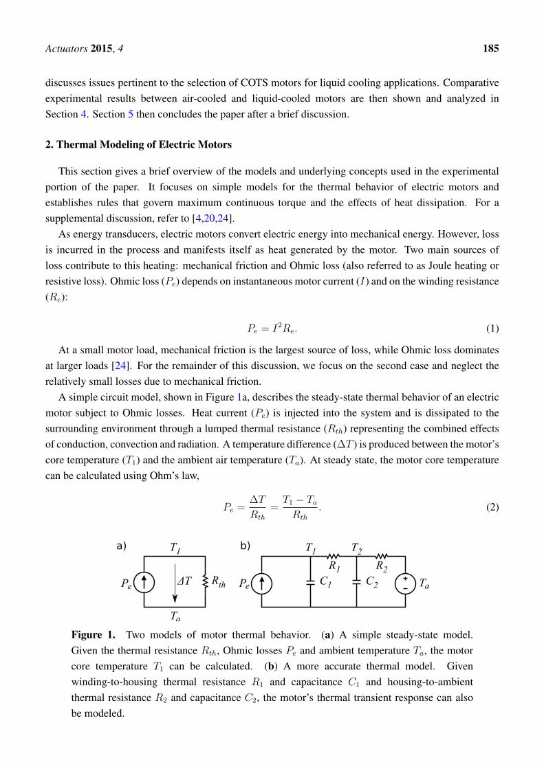
A simple circuit model, shown in Figure 1a, describes the steady-state thermal behavior of an electricmotor subject to Ohmic losses. Heat current (Pe) is injected into the system and is dissipated to thesurrounding environment through a lumped thermal resistance (Rth) representing the combined effectsof conduction, convection and radiation. A temperature difference (∆T ) is produced between the motor’score temperature (T1) and the ambient air temperature (Ta). At steady state, the motor core temperaturecan be calculated using Ohm’s law,
Pe =∆T
Rth
=T1 − TaRth
. (2)
Figure 1. Two models of motor thermal behavior. (a) A simple steady-state model.Given the thermal resistance Rth, Ohmic losses Pe and ambient temperature Ta, the motorcore temperature T1 can be calculated. (b) A more accurate thermal model. Givenwinding-to-housing thermal resistance R1 and capacitance C1 and housing-to-ambientthermal resistance R2 and capacitance C2, the motor’s thermal transient response can alsobe modeled.

Actuators 2015, 4 186
Given the maximum permissible motor winding temperature (T1max), we can combine Equations (1)and (2) to calculate the maximum thermally-permissible continuous current,
Ic =
√T1max − TaRthRe
(3)
noting that Rth is a thermal resistance, while Re is an electrical resistance.Equation (3) depends on Re, which is itself a function of temperature. This relationship is defined by
the resistor temperature coefficient equation [25],
Re(T ) = Ro[1 + α(T − To)] (4)
where Ro is the nominal resistance at the nominal temperature (To) and α is the winding material’stemperature coefficient (copper has an α of around 0.0039 Ω/K).
From Equation (3), we can see how Rth plays a critical role in determining maximum continuouscurrent. The other parameters, T1max , Ta and Re, cannot be significantly altered from nominal values.Alternatively, Rth is very sensitive to design and environmental factors.
To further this analysis, consider the thermal model illustrated in Figure 1b. Here, additional elementsare included: R1 to represent the thermal resistance between the motor core and the motor housing, C1
to represent the thermal capacitance of the motor’s core, R2 to represent the thermal resistance betweenthe motor housing and the environment, C2 to represent the thermal capacitance of the motor’s housingand Ta to represent ambient temperature. Several motor manufacturers provide these parameters inmotor datasheets. This model improves over Figure 1a in that it more accurately captures the transientresponse of the motor to a thermal load and also breaks down the lumped thermal resistance into twodistinct components.
From Equation (3), it is clear that Rth must be minimized to maximize a motor’s torque to mass ratio.This is a central consideration for any high-performance motor design and is often addressed either byusing forced convective air cooling [1] or by adopting liquid cooling [10,12,18]. Table 1 demonstratesthe benefits of liquid cooling with water, where water exhibits up to a 50× improvement in convectiveheat transfer compared to air. Table 1 gives a range for each situation due to a number of factors affectingconvective heat transfer, such as the rate of fluid flow and surface shape.
Table 1. Typical values for mean convective heat transfer coefficient [26].
Flow Situation and Fluid Mean Heat Transfer Coefficient [W/(m2K)]
Free convection in air 3 to 20Forced convection in air 10 to 200Free convection in water 20 to 200
Forced convection in water 40 to 10,000

Actuators 2015, 4 187
2.1. Thermal Ratio
In the case of liquid cooling, custom motor designs typically pass cooling fluid as close to theheat-generating windings as possible in order to reduce Rth. However, custom motor designs are notalways possible, either for cost, time or complexity reasons. An alternative design is to apply liquidcooling to COTS motors to improve their performance [20–22]. In this case, the fundamental design ofthe motor cannot be altered. This consideration implies thatR1 must stay fixed whileR2 may be reducedusing liquid cooling. Taking this constraint into consideration, we can define the thermal ratio (ρ) of amotor to be the maximum achievable improvement of continuous current (Equation (3)) assuming R1
must remains fixed and R2 can be made close to zero using liquid cooling. The thermal ratio is derivedby taking the ratio of two continuous currents, one with with Rth = R1, (Icl) and the second withRth = R1 +R2, (Ica):
ρ =IclIca
=
√R1 +R2
R1
. (5)
Figure 2 shows the thermal ratio for several Maxon motors. As the figure shows, the type of motorand its design significantly affect the potential benefit of adding liquid cooling. Assuming the addedheat can be adequately dissipated, a central issue that will be discussed further in Section 5, the EC25250 W Maxon motor should be able to tolerate over 8× the continuous current of air cooling when liquidcooling is applied, while the RE65 250 W motor’s continuous current is only increased by 1.56×.
The
rmal
Rat
io
0
1
2
3
4
5
6
7
8
9
RE40 1
50W
RE65 2
50W
EC6
2W
EC22 1
00W
EC25 2
50W
EC-4po
le30
200W
EC60 4
00W
Thermal ratio of several Maxon motors
Figure 2. Thermal ratios of several Maxon motors. The thermal ratio is the theoreticalimprovement factor in continuous current of liquid cooling versus air cooling. Part numbersbeginning with ‘RE’ are brushed DC motors, while part numbers beginning with ‘EC’ arebrushless DC motors.

Actuators 2015, 4 188
2.2. Core Temperature Estimation
While liquid cooling may significantly improve continuous current output of electric motors, it doesnot have the same effect on short-term current output. To gain insight into the maximum permissibleshort-term current output, [20] introduced the thermal control concept, which is a method to estimatethe core motor temperature based on current and previous state measurements. This method is moreeffective than placing a temperature sensor directly on the motor’s windings due to the temperaturedifference between the winding core and its surface and the winding’s associated thermodynamics. Here,the thermal control approach is briefly described and is applied later in Section 4.
Two differential equations fully describe the thermal circuit model shown in Figure 1b:
dT1dt
=1
C1
[Pe −
T1 − T2R1
](6a)
dT2dt
=1
C2
[T1 − T2R1
− T2 − TaR2
](6b)
Given accurate initial conditions and measurements of Pe (by measuring motor current) and Ta, theseequations can be integrated in real time using, for example, Euler integration, to estimate the values ofT1 and T2. If T2 is directly measured, as it is in our experimental testbed, then T1 can be calculated fromEquation (6a) alone.
3. Design of the Liquid-Cooled Motor System
This section describes the design of a retrofitted liquid-cooled motor and the auxiliary systemsrequired for accurately measuring and characterizing its performance.
3.1. Motor Selection
Motor selection was driven by a variety of factors. In addition to the typical motor performancerequirements, such as large torque/mass and power/mass, a COTS motor used with liquid cooling shouldsatisfy several additional requirements:
1. High magnetic saturation: Because of the large currents experienced with liquid cooling, theselarge currents must not saturate any flux-producing elements of the motor. Motors with iron coresare more susceptible to this effect than are coreless motor designs [27].
2. Low thermal resistance: The proximity of the heat-generating winding to the outside surface of amotor varies greatly by motor type and motor design (refer back to Figure 2). In the case that R1
and R2 are not provided by the motor manufacturer, motor designs featuring stationary windingswith a short thermal path to the liquid-cooled surface are desirable. Motor types matching thesecharacteristics are internal rotor brushless DC/AC motors and stepper motors. Poor candidates areexternal rotor brushless DC/AC, brushed DC, universal and induction motors.

Actuators 2015, 4 189
In the present case, along with a desired power range of 100 W to 200 W, the following two metricswere used to choose the EC22 100-W motor from the Maxon catalog:
Continuous Power · Thermal RatioMass · Cost
(7a)
Continuous Torque · Thermal RatioMass · Cost
(7b)
Table 2 shows the datasheet thermal parameters for the EC22 100-W motor.
Table 2. Maxon EC22 100-W datasheet thermal parameters.
Parameter Value Units
R1 1 K/WR2 7 K/WRe 0.797 Ω
T1max 155 C
From Equation (5), the thermal ratio for this motor is calculated to be 2.83, yielding a theoreticalair-cooled continuous current of 3.71 A (Equation (3)) assuming an ambient temperature of 25 C. Forthis case, Ohmic losses would be 16.2 W. Using liquid cooling, continuous current is increased to 10.5 A,generating Ohmic losses of 130 W. The next section describes how this large amount of heat is efficientlycarried away from the motor case.
3.2. Retrofitted Liquid-Cooled Motor Housing Design
A fluid conducting housing was designed to fit a Maxon EC22 100-W motor with three main goals:(1) provide a water-tight seal around the motor for the 1.5-bar fluid pressure generated by the liquidcooling pump; (2) ensure the fluid is circulated over the entire surface of the motor, limiting eddy currentswhere possible; and (3) produce a design that may be disassembled for cleaning and maintenanceif needed.
To satisfy these requirements, a unique design was developed that is composed of three sections(see Figure 3). The front-most sections, where the motor’s output shaft is located, serve as both themechanical and fluid interface for the motor. Requiring mechanical strength, corrosion resistance,chemical inertness and high machining tolerances, this section is CNC-machined from Delrin plastic(also known as polyoxymethylene). Two fluid seals, one a COTS silicone O-ring with a 70-A durometerhardness and one custom-designed laser-cut from EPDM (ethylene-propylene-diene monomer) rubberwith a 60-A durometer hardness are designed for a 30% squeeze (O-ring compression) to provide awatertight barrier.
The middle section of the liquid-cooled motor housing circulates the fluid around the full surface ofthe motor, following a ribbed design similar to that of [22]. Requiring lower tolerances (±0.127 mm),cost is saved by 3D printing this part from watertight acrylic polymer using a UV curing process. Anadditional set of O-rings provides a seal to the third, rear-most part of the housing, which is retained

Actuators 2015, 4 190
to the rest of the assembly with screws. Unlike [22], which uses sealing adhesive to join housingcomponents together, this O-ring-based design better facilitates disassembly, allowing for componentreuse and periodic maintenance, if required.
Figure 3. Design of a casing to house and circulate cooling fluid around the Maxon EC22100-W motor.
Motor case temperature is measured using a pre-calibrated thermistor. The thermistor is securedto the motor case with thermally-conductive epoxy (also known as potting compound) with a thermalconductivity of 0.682 W/mK, similar to that of water. One hole must be drilled into the middle part ofthe liquid cooling housing assembly through which the thermistor’s leads are routed. A non-permanentroom-temperature vulcanized silicone rubber seal is used at this interface.
3.3. Retrofitted Liquid-Cooled Servo Drive Water Block Design
Because motor current also must pass through the motor servo drive, a water block was designed tocool this component, as well. Its design requirements are similar to that of the motor’s liquid coolinghousing. Figure 4 illustrates this design. CNC-machined Delrin is again used for the body of theassembly, while a custom-designed gasket provides the watertight seal. Copper was chosen to carryheat away from the servo drive (Advanced Motion Controls AZB60A8), but aluminum will likely beused in the next iteration for its lower density. A single channel is machined into the housing of thewater block to force liquid to pass over the portion of the heat sink where heat is most concentrated.
The remaining liquid cooling components such as the radiator, reservoir, pump and fittings, wereobtained from Swiftech, a personal computer (PC) liquid cooling company. High-flex PVC (polyvinylchloride) tubing was used to connect these components together. Optimal sizing of the liquid cooling

Actuators 2015, 4 191
components remains an important question to be addressed in future work. In the present testbed, theflow rate of the coolant through the combined fluid resistances of the motor housing, servo drive waterblock and radiator was measured to be 0.036 L/s.
Figure 4. Design of a casing to house and circulate cooling fluid around the AdvancedMotion Controls AZB60A8 motor driver.
3.4. Instrumentation and Dynamometry Design
A controllable motor load and a large suite of sensors is necessary to enable thermal control andto fully characterize motor performance (see Figures 5 and 6). A hysteresis brake (Magtrol HB-840)capable of dissipating 300-W continuous and 1340-W peak power is used as a variable motor load. Witha thermal ratio of 2.83, the liquid-cooled EC22 100-W motor is expected to produce 283 W of powercontinuously. The brake’s maximum speed is 6000 rpm, while the motor’s maximum speed, driven by a64-V battery supply, is 43,000 rpm. Therefore, a 7.68:1 two-stage pulley speed reduction is used betweenthe motor and the hysteresis brake to match their respective maximum speeds.
The following measurements are taken on the motor testbed:
1. Motor torque is measured using a reaction torque sensor (Futek TFF325).2. Motor speed is measured based on the time between hall sensor signal pulses.3. Motor current is monitored using feedback from the motor servo drive (Advanced Motion Controls
AZB60A8).4. Bus voltage is measured directly across the battery output terminals.5. Bus current is measured from the negative battery terminal lead using a Hall effect sensor.

Actuators 2015, 4 192
6. Motor case temperature is measured using a potted negative temperature coefficient(NTC) thermistor.
7. Servo drive temperature is measured using a potted NTC thermistor.8. Fluid reservoir temperature is measured using an NTC thermistor.
Figure 5. The motor testbed used in Section 4. This picture shows the testbed as configuredfor liquid cooling. For air cooling tests, a bare motor was used. This system is interfaced toa Texas Instruments TMS320F28335 microcontroller (refer to Figure 6 below).
EtherCAT ET1100 ASIC
TI Delfino F28335 uC
Motordriver
Battery
Load cell
Hysteresisbrake
BLDCMotor
Radiator
Pump
thermistors
SPI
grou
nd c
onne
ction
current cmd
current monitor
curre
nt se
ns
e
voltage s
ense coolant
Fans
Analog circu
itry
Hall Sensors
Powersupply
Control PC(Ubuntu 14.04)
EtherCAT
fluid resevoirExperimental Setup of Motor Testbed
Figure 6. A block diagram showing the hardware interface used for experimental testing.Data are gathered on a Texas Instruments TMS320F28335 microcontroller and then passedto a control PC via EtherCAT.

Actuators 2015, 4 193
Coupled with the programmable hysteresis brake, this set of sensors enables thermal control and alsodirect measurement of input power, output power and, therefore, overall actuation system efficiency.Efficiency is measured as the ratio of mechanical output power to electrical input power as illustratedin Figure 7. For efficiency measurement in this paper the additional power consumption of the liquidcooling pump is not considered. In the present testbed, the power consumed by the pump is relativelysmall compared to the maximum continuous power consumed by the motor (2.2%, 12 W versus 533 W).In a real robotic system, this discrepancy would likely be larger, since a single pump can provide fluidflow to multiple motors. The efficiency measured by the testbed does include hysteresis, eddy currentand Ohmic losses in the motor, as well as switching and Ohmic losses in the motor driver.
Battery Servo drive Motor Load
Input power measurement Output power measurement
Belttransmission
Figure 7. Location of power measurements in the motor testbed. Electrical power ismeasured from the power source (batteries) as voltage times current. Mechanical poweris measured at the motor’s output as angular velocity times torque. Measured efficiencytherefore includes the motor and servo drive losses.
4. Experimental Comparison between Air- and Liquid-Cooled Motors
The central goal of this work was to empirically determine and compare the maximum continuouspower and torque production of air- and liquid-cooled motors. To achieve this objective, the problemwas subdivided into four stages or experiments:
1. Experiment 1: establish the maximum continuous motor current using air cooling and a fixed load.
2. Experiment 2: measure the maximum output power and torque using continuous current, aircooling and a variable load.
3. Experiment 3: establish the maximum continuous motor current using liquid cooling and afixed load.
4. Experiment 4: measure the maximum output power and torque using continuous current, liquidcooling and a variable load.
4.1. Experimental Setup
Motor commands and all sensor data were interfaced through a Texas Instruments TMS320F28335microcontroller as depicted in Figure 6. Data were transmitted to a control PC running Ubuntu 14.04 viaEtherCAT fieldbus. Due to the long duration of each test, sample rates between 100 Hz and 20 Hz wereused. The hysteresis brake was interfaced to a separate power supply, and its torque, which is measuredwith the testbed torque sensor, was set manually. Five 12-V lead acid batteries were used to supplybetween 60 V and 70 V to the motor driver.

Actuators 2015, 4 194
In the process of performing tests that reach the maximum safe motor core temperatures, it isimportant to be able to discern if and when damage to the motor occurs. System operating efficiencyis used for this purpose, and it is assumed that it corresponds to the health of the motor. Between eachhigh current experiment, a test is run to measure system operating efficiency. In this way, we are able todetect if and when motor damage occurs.
4.2. Experiment 1: System Identification of Air-Cooled Motor
In this experiment, a stock motor without liquid cooling was used. The commanded motor current wasfirst calibrated against an oscilloscope current probe attached to the motor phase wires. After calibration,a constant current was applied to the motor, and the hysteresis brake torque was set such that a low motorspeed was achieved (between 2000 rpm and 3000 rpm). Through trial and error, the magnitude of thecurrent was set such that the estimated core motor temperature would reach close to a steady-state valueof 155 C, the maximum rated winding temperature. Figure 8 shows the final result.
Time(s)0 200 400 600 800 1000 1200 1400 1600 1800 2000
Tem
pera
ture
(C
)
0
50
100
150
R1 =1[K/W]
τ1 =4.92[s]
R2 =5.2[K/W]
τ2 =250[s]
Ta =22.837[C]
I =4.07[A]T1
ss
=141.9343[C]
T2ss
=122.725[C]
Pess
=19.2092[W]
Air Cooling Temperature Step Response
Meas. case tempEst. core tempSim. core tempSim. case tempAmbient temp
Figure 8. Thermal step response of the Maxon EC22 100-W motor with air cooling. Acurrent amplitude of 4.07 A was used. This amplitude was empirically determined andcauses the core motor temperature to reach an estimated steady-state value of 141.9 C(a safety margin of 13.1 C compared to the maximum rated value of 155 C). The coretemperature was estimated using the thermal control technique described in Section 2.2.Actual data are plotted as points, while the lines are simulated responses and were used to fitthe thermal model (from Figure 1b) to the data.
Figure 8 also shows the empirically-identified thermal model parameters R1, τ1 = R1C1, R2,
τ2 = R2C2, along with the experimental parameters. Our identified thermal parameters match thedatasheet values except for R2, which is 74% of the datasheet value (5.2 K/W vs. 7 K/W). This isan acceptable difference given the sensitivity of thermal resistance to environmental conditions, suchas mounting conditions, air currents, etc. The simulated core temperature (Sim. core temp) and casetemperature (Sim. case temp) lines are extrapolations of the experimental data and are used to determine
Actuators 2015, 4 195
the steady-state value of the core temperature. These simulated values are generated using a Simulinkmodel of the thermal circuit (Figure 1b).
The end result of this experiment is a continuous current value of 4.07 A (corresponding to 0.06 Nm oftorque), which is 14% greater than the datasheet value of 3.57 A. This difference is due to the discrepancybetween the datasheet and measured R2 value. This continuous current and torque will serve as ourbaseline for comparison with the liquid cooling experiments.
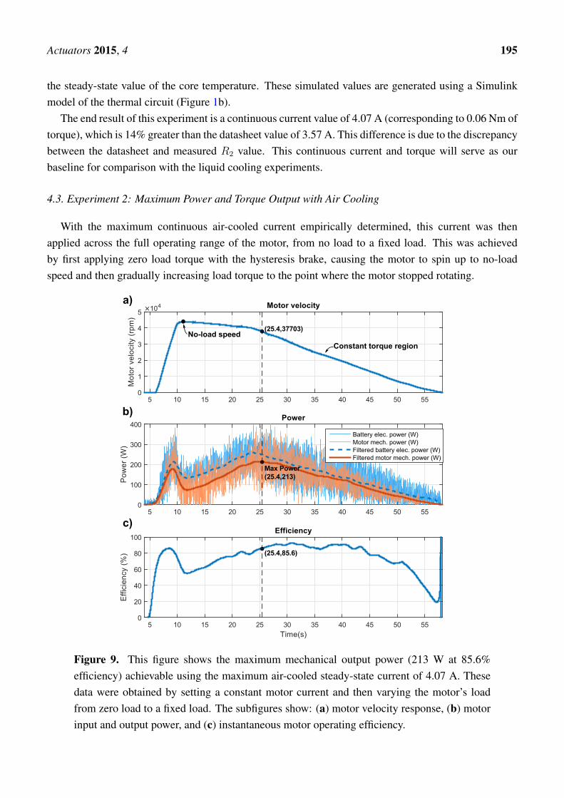
4.3. Experiment 2: Maximum Power and Torque Output with Air Cooling
With the maximum continuous air-cooled current empirically determined, this current was thenapplied across the full operating range of the motor, from no load to a fixed load. This was achievedby first applying zero load torque with the hysteresis brake, causing the motor to spin up to no-loadspeed and then gradually increasing load torque to the point where the motor stopped rotating.
Figure 9. This figure shows the maximum mechanical output power (213 W at 85.6%efficiency) achievable using the maximum air-cooled steady-state current of 4.07 A. Thesedata were obtained by setting a constant motor current and then varying the motor’s loadfrom zero load to a fixed load. The subfigures show: (a) motor velocity response, (b) motorinput and output power, and (c) instantaneous motor operating efficiency.

Actuators 2015, 4 196
The results of this experiment are shown in Figure 9. Figure 9a shows motor velocity, which first risesrapidly to the no-load speed, decreases with increasing load until it reaches the constant torque regionand then decreases linearly to zero. Figure 9b shows both electrical input power and mechanical outputpower. Power data were filtered with a zero-phase moving average filter with a window size of 1.5 s.From this plot, the maximum continuous power point can be identified (213 W at 25.4 s). Figure 9cshows the overall system efficiency. The efficiency during peak power output is 85.6%. Efficiency peaksat around 92.5%, which is close to the datasheet value of 90%.
4.4. Experiment 3: System Identification of the Liquid-Cooled Motor
For the third experiment, liquid cooling was installed onto the motor and the servo drive. As aninitial test, the motor current was set to follow a 7-A sine wave with no fluid circulation (see Figure 10).Then, after the motor case temperature had risen to 50 C, the pump for the liquid cooling system wasturned on. In one second, the case temperature dropped by 24 C back to ambient temperature (23.2 C),demonstrating the importance of fluid flow in the convective heat transfer of liquid cooling.
Figure 10. This figure demonstrates the effect of fluid flow on cooling performance. Fromt = 0→180 s, a sinusoidal current with an amplitude of 7 A, generating peak Ohmic lossesof around 40 W, is applied to the motor. During this time, fluid around the motor is slowlyheated. At t = 180 s, the liquid cooling pump is turned on, causing the fluid to begin flowingpast the radiator. A rapid decrease in motor case temperature follows, dropping 24 C backdown to ambient temperature in 1 s.
To identify the maximum steady-state current, the commanded currents were increased until themaximum core temperature was reached with a safety margin of 24 C. Figure 11 demonstrates theidentified maximum continuous current of 9.65 A (0.15 Nm of torque), reaching a core temperature of131 C. Note that the identified model for this case uses an R2 value of 0.0325 K/W, meaning that thethermal resistance is smaller than that of ambient air cooling by a factor of 160 (5.2/0.0325). This is a

Actuators 2015, 4 197
significant improvement and is also sufficiently close to zero to verify the assumption of setting R2 tozero to calculate the thermal ratio, as described in Section 2.1.
Time(s)0 100 200 300 400 500 600 700
Tem
pera
ture
(C
)
0
20
40
60
80
100
120
140
R1 =1[K/W]
τ1 =4.92[s]
R2 =0.0325[K/W]
τ2 =125[s]
Ta =23.1184[C]
I =9.65[A]T1
ss
=131.4283[C]
T2ss
=26.5277[C]
Pess
=104.9006[W]
Liquid Cooling Temperature Step Response
Meas. case tempEst. core tempSim. core tempSim. case tempAmbient temp
Figure 11. Thermal step response of the Maxon EC22 100-W motor with liquid cooling.A current amplitude of 9.65 A was used. This amplitude was empirically determined andcauses the core motor temperature to reach an estimated steady-state value of 131.42 C. Thecore temperature was estimated using the thermal control technique described in Section 2.2.Experimental data are plotted as points, while the lines are simulated responses and wereused to fit the thermal model (from Figure 1b) to the data.
4.5. Experiment 4: Maximum Power and Torque Output with Liquid Cooling
The experimental procedure for the fourth experiment mirrored that of Experiment 2. The maximumliquid-cooled continuous current was set, and the load was then decreased from no load to a fixedload. Velocity, power and efficiency were measured as shown in Figure 12. Figure 12b shows thatthe maximum continuous power was produced at t = 20.4 s, reaching a value of 430 W at 83.4% overallefficiency. Surprisingly, despite the dramatic increase in power by a factor of two, the overall decreasein efficiency between these two operating points is only 2.2% (85.6% versus 83.4%).
4.6. Empirical Comparison of the Cooling Methods
By compiling the various trials of Experiments 1 and 3, the performance of air cooling can be directlycompared against that of liquid cooling. Figure 13 shows these results. The data points on the plotare the steady-state temperatures gathered during the separate trials of Experiments 1 and 3. A best fitcurve was applied to both sets of data to allow direct comparison of the two cooling methods at the samesteady-state core temperature. Based on this approach, liquid cooling the Maxon EC22 100-W motorresults in an improvement in steady-state current by a factor of 2.58. This empirical value matches towithin 9% of the motor’s datasheet thermal ratio value of 2.83 and is lower due to the experimentaldiscrepancy of the R2 parameter.

Actuators 2015, 4 198
No-load speed
Constant torque region
a)
b)
c)
Figure 12. This figure shows the maximum mechanical output power (430 W at 83.4%efficiency) achievable using the maximum liquid-cooled steady-state current of 9.65 A.These data were obtained by setting a constant motor current and then varying the motor’sload from zero load to a fixed load.
Figure 13. This figure compares the performance of air versus liquid cooling as appliedto the COTS Maxon EC22 100-W motor. Here, the performance metric is steady-statecontinuous current. Maximum current is defined to be the current that produces a steady-statecore temperature of 155 C. By this metric, liquid cooling outperforms air cooling by a factorof 2.58 (4.07 A versus 10.5 A) for the Maxon EC22 100-W motor. This factor is motordependent, but is accurately approximated (in this case to within 9%) by the motor’s thermalratio (2.83 for the Maxon EC22 100 W; refer back to Section 2.1).

Actuators 2015, 4 199
5. Conclusion and Discussion
This paper directly compared the achievable torque and power improvements yielded by constructinga retrofitted liquid cooling system for a COTS electric motor. It was found that, for the MaxonEC22 100 W motor, 2.58-times higher current and torque output could be safely obtained with theliquid-cooled motor compared to the same motor with air cooling. This improvement factor closelymatched the motor’s thermal ratio, a theoretical value that can be directly calculated from datasheetmotor parameters. This empirical validation is the main contribution of the paper and enables futuredesigners to place confidence in and have intuition towards active cooling performance for COTS motors.An increase in continuous power output by a factor of two between the two cooling methods was alsomeasured, and importantly, this increase fostered a mere 2.2% decrease in operating efficiency. Thisobservation suggests that liquid cooling may also serve roles in actuators with strict energy consumptionrequirements, yet that are required to produce high energy output periodically.
We presented a new design for a retrofitted liquid cooling housing, which features high coolingperformance (reaching a thermal resistance of R2 = 0.035 K/W), but that is based on a non-permanentO-ring-sealed structure. This improves over existing designs in that the cooling structure can bedisassembled and cleaned periodically. The empirical measurement of the parameter R2 is also useful inthat it provides a data point for the performance of the heat convection in liquid-cooled COTS motors.Comparing the value of R2 with liquid cooling (0.035 K/W) against its air-cooled counterpart (5.2 K/W)resulted in a reduction of thermal resistance by a factor of 160. This yields a data point of
√160 = 12.6
for the thermal ratio of a “thermally-optimized” motor, where R1 ≈ 0, meaning cooling fluid is passeddirectly over the windings. This value is, of course, related to the many factors associated with ourparticular liquid-cooled system, such as the outside surface area of the Maxon EC22 100-W motor, thesize of the radiator, the number of cooling fans used, etc., and therefore is not a hard theoretical limit,only a single, empirically-derived data point.
An additional question to ask is “how may these methods be applied to motors without pre-specifiedthermal properties?” In this case, a more thorough system identification process must be used whereall four parameters, R1, C1, R2, C2 are empirically identified. In this paper, R2 was identified bycommanding a constant current, letting the system reach a steady-state temperature and then measuringthe difference between T2 and Ta. With R2 identified, C2 was found based on the system’s transientresponse. Accurately identifying R1 and C1 is more difficult. Approaches for measuring these valuescould leverage the fact that winding resistance is a function of temperature thus enabling its use as atemperature sensor.
Future work remains in the best sizing of liquid cooling components, such as the radiator, pump andtubing diameter for optimal system-wide power/torque per unit mass. Additionally, limited attemptswere made in this work to optimize pressure versus flow characteristics of the motor and driverwater blocks. Improvements here may improve cooling performance further, leading to improvedempirically-measured thermal ratios.
Acknowledgments
The authors would like to thank Joseph Ho and Aloysius Mok for their contributions to this work.

Actuators 2015, 4 200
Author Contributions
Nicholas Paine built the experimental testbed and wrote the majority of the manuscript text. LuisSentis oversaw and directed the project and provided valuable input for the manuscript.
Conflicts of Interest
The authors declare no conflict of interest.
Abbreviations/Nomenclature
COTS: commercial off-the-shelfCNC: computer numerical control
References
1. Radford, N.A.; Strawser, P.; Hambuchen, K.; Mehling, J.S.; Verdeyen, W.K.; Donnan, A.S.;Holley, J.; Sanchez, J.; Nguyen, V.; Bridgwater, L.; et al. Valkyrie: NASA’s First BipedalHumanoid Robot. J. Field Robot. 2015, 32, 397–419.
2. Veneman, J.F.; Kruidhof, R.; Hekman, E.E.; Ekkelenkamp, R.; Van Asseldonk, E.H.;Van Der Kooij, H. Design and evaluation of the LOPES exoskeleton robot for interactive gaitrehabilitation. IEEE Trans. Neural Syst. Rehabil. Eng. 2007, 15, 379–386.
3. Ridley, J. The MRV: Next-Gen Automobile? Available online:http://www.electricvehiclesresearch.com/articles/7731/the-mrv-next-gen-automobile (accessedon 13 August 2015).
4. Hunter, I.W.; Hollerbach, J.M.; Ballantyne, J. A comparative analysis of actuator technologiesfor robotics. In Robotics Review 2; MIT Press: Cambridge, MA, USA, 1991; pp. 299–342.
5. Zoss, A.B.; Kazerooni, H.; Chu, A. Biomechanical design of the Berkeley lower extremityexoskeleton (BLEEX). IEEE/ASME Trans. Mechatron. 2006, 11, 128–138.
6. Pratt, G.A. DARPA-BAA-12-52: Broad Agency Announcement, Maximum Mobility andManipulation, Actuation; Technical report; DARPA: Arlington, MA, USA, 2012.
7. Caricchi, F.; Crescimbini, F.; Napoli, A.; Marcheggiani, M. Prototype of electric vehicle drivewith twin water-cooled wheel direct drive motors. In Proceedings of the 27th Annual IEEE PowerElectronics Specialists Conference, Baveno, Italy, 23–27 June 1996; Volume 2, pp. 1926–1932.
8. Rahman, K.M.; Patel, N.R.; Ward, T.G.; Nagashima, J.M.; Caricchi, F.; Crescimbini, F.Application of direct-drive wheel motor for fuel cell electric and hybrid electric vehiclepropulsion system. IEEE Trans. Ind. Appl. 2006, 42, 1185–1192.
9. Snitchler, G.; Gamble, B.; Kalsi, S.S. The performance of a 5 MW high temperaturesuperconductor ship propulsion motor. IEEE Trans. Appl. Superconduct. 2005, 15, 2206–2209.
10. Everton, J.; Schofield, N. Design and testing of a liquid cooled brushless DC traction motor.In Proceedings of the IEE Colloquium on Motors and Drives for Battery Powered Propulsion,London, UK, 15 April 1993.
11. Bianchi, N.; Gieras, J. Electric motors for light traction. EPE J. 2004, 14, 12–23.

Actuators 2015, 4 201
12. Laskaris, K.; Kladas, A.G. Liquid cooled permanent-magnet traction motor design consideringtemporary overloading. In Proceedings of the 2012 XXth International Conference on ElectricalMachines (ICEM), Marseille, France, 2–5 September 2012; pp. 2677–2682.
13. Van Es, J.; van Gerner, H.J. Benefits and Drawbacks of Using Two-Phase Cooling Technologies inMilitary Platforms; Technical report; National Aerospace Laboratory: Amsterdam, Netherlands,2011.
14. Rogers, S.; Boyd, S. Overview of the DOE Advanced Power Electronics and Electric Motor R&DProgram; Technical report; U.S. Department of Energy: Washington, DC, USA, 2014.
15. Asada, H.; Youcef-Toumi, K. Direct-Drive Robots: Theory and Practice; MIT Press: Cambridge,MA, USA, 1987.
16. Hollerbach, J.; Hunter, I.; Lang, J.; Umans, S.; Sepe, R.; Vaaler, E.; Garabieta, I. The McGill/MITdirect drive motor project. In Proceedings of the 1993 IEEE International Conference on Roboticsand Automation, Atlanta, GA, USA, 2–6 May 1993; pp. 611–617.
17. Aghili, F.; Buehler, M.; Hollerbach, J.M. Development of a high-performance direct-drive joint.Adv. Robot. 2002, 16, 233–250.
18. Aghili, F.; Hollerbach, J.M.; Buehler, M. A modular and high-precision motion control systemwith an integrated motor. IEEE/ASME Trans. Mechatron. 2007, 12, 317–329.
19. Harmonic Drive LLC. Cup Type Component Sets & Housed Units. Available online:http://harmonicdrive.net/media/support/catalogs/pdf/csf-csg.pdf (accessed on 28 July 2015).
20. Urata, J.; Hirose, T.; Namiki, Y.; Nakanishi, Y.; Mizuuchi, I.; Inaba, M. Thermal control ofelectrical motors for high-power humanoid robots. In Proceedings of the IEEE/RSJ InternationalConference on Intelligent Robots and Systems (IROS 2008), Nice, Italy, 22–26 September 2008;pp. 2047–2052.
21. Urata, J.; Nakanishi, Y.; Okada, K.; Inaba, M. Design of high torque and high speed leg modulefor high power humanoid. In Proceedings of the 2010 IEEE/RSJ International Conference onIntelligent Robots and Systems (IROS), Taipei, Taiwan, 18–22 October 2010; pp. 4497–4502.
22. Ito, Y.; Nozawa, S.; Urata, J.; Nakaoka, T.; Kobayashi, K.; Nakanishi, Y.; Okada, K.; Inaba, M.Development and verification of life-size humanoid with high-output actuation system. InProceedings of the 2014 IEEE International Conference on Robotics and Automation (ICRA),Hong Kong, China, 31 May–7 June 2014; pp. 3433–3438.
23. DARPA. The DARPA Robotics Challenge Trials. 2013. Avaiable online: http://archive.darpa.mil/roboticschallengetrialsarchive/ (accessed on 30 June 2015).
24. Stemme, D.O.; Wolf, P. Principles and Properties of Highly Dynamic DC Miniature Motors;Maxon Motor: Sachseln, Switzerland, 1994.
25. Kasap, S.O. Principles of Electronic Materials and Devices; McGraw-Hill: New York, NY, USA,2006.
26. Oosthuizen, P.H.; Naylor, D. Introduction to Convective Heat Transfer Analysis; McGraw-Hill:New York, NY, USA, 1999.

Actuators 2015, 4 202
27. Maxon Motor. Permanent Magnet DC Motor with Coreless Winding; Technical report; MaxonMotor: Obwalden, Switerland, 2012.
c© 2015 by the authors; licensee MDPI, Basel, Switzerland. This article is an open access articledistributed under the terms and conditions of the Creative Commons Attribution license(http://creativecommons.org/licenses/by/4.0/).