Design and Application Details - Lesman · Page 2754 TUBE-O-THERM® Gas Burners Design and...
12
TUBE-O-THERM ® Gas Burners Page 2753 10/99 Design and Application Details Maxon TUBE-O-THERM ® Burners are nozzle- mixing, gas fired, refractory-less burners specifically designed for firing into a small bore tube. Typical applications are industrial solution heating jobs such as dip tanks, spray washers, pickling or quench tanks, salt baths, indirect air heaters and bakery ovens. TUBE-O-THERM ® Burners are available in two basic versions: 1) packaged with integral low horse- power combustion air blower in your choice of the voltages listed below, or 2) EB (external blower) for use with an external combustion air source. Standard TUBE-O-THERM ® Burner package (shown below) includes a combustion air blower with a non-sparking aluminum impeller. A built-in pilot and spark ignitor is included in the cast iron burner body, as well as the air and gas control valves, gas nozzle, pilot adjustable orifice and provisions for your flame scanner. Burner design permits blower to be rotated at 90° intervals around centerline for application flexibility. 3" EB TUBE-O-THERM ® Burner with control motor Model EB (external blower) TUBE-O-THERM ® Burners (shown below), like all TUBE-O-THERM ® Burner assemblies, are designed to deliver heat efficiently into your fired tube application. Wall or tube stub mounting options simplify installation on your application. Mounting dimensions for tube stub option correspond to standard ANSI 150# flange sizes. Low torque requirements permit use of virtually any electric operator. Maxon supplies connecting base and linkage assemblies for mounting most temperature control operators. Principle of operation (illustrated below) Both versions incorporate a gas and air valve linked together to control the gas-air ratio over the full throttling range of the burner. Gas flows out through the gas nozzle where it mixes with the combustion air. Natural gas, propane or butane can be used. 3" TUBE-O-THERM ® Gas Burner with customer’s control motor and UV scanner mounted M R E H T - O - E B U T ® l e d o M r e n r u B " 3 . d k P " 4 . g k P " 6 . g k P " 8 . g k P r e w o p e s r o H P H 2 / 1 P H 2 / 1 P H 2 P H 3 ) . d t s ( 0 6 / 3 / 0 6 4 / 0 3 2 - 8 0 2 X X X X 0 6 / 1 / 0 3 2 / 5 1 1 X X X A N * 0 5 / 3 / 0 8 3 - 0 9 1 X X X X 0 6 - 3 - 5 7 5 X X X X e g r a h c a r t x e t a n o i t p o r o t o m z t r e h 0 5 *
Transcript of Design and Application Details - Lesman · Page 2754 TUBE-O-THERM® Gas Burners Design and...
TUBE-O-THERM® Gas Burners Page 2753
10/99
Design and Application Details
Maxon TUBE-O-THERM® Burners are nozzle-mixing, gas fired, refractory-less burners specificallydesigned for firing into a small bore tube. Typicalapplications are industrial solution heating jobs suchas dip tanks, spray washers, pickling or quench tanks,salt baths, indirect air heaters and bakery ovens.
TUBE-O-THERM® Burners are available in twobasic versions: 1) packaged with integral low horse-power combustion air blower in your choice of thevoltages listed below, or 2) EB (external blower) foruse with an external combustion air source.
Standard TUBE-O-THERM ® Burner package(shown below) includes a combustion air blower witha non-sparking aluminum impeller. A built-in pilot andspark ignitor is included in the cast iron burner body,as well as the air and gas control valves, gas nozzle,pilot adjustable orifice and provisions for your flamescanner. Burner design permits blower to be rotatedat 90° intervals around centerline for applicationflexibility.
3" EBTUBE-O-THERM®
Burner with controlmotor
Model EB (external blower) TUBE-O-THERM ®
Burners (shown below), like all TUBE-O-THERM®
Burner assemblies, are designed to deliver heatefficiently into your fired tube application.
Wall or tube stub mounting options simplifyinstallation on your application. Mounting dimensionsfor tube stub option correspond to standard ANSI150# flange sizes.
Low torque requirements permit use of virtuallyany electric operator. Maxon supplies connectingbase and linkage assemblies for mounting mosttemperature control operators.
Principle of operation (illustrated below)
Both versions incorporate a gas and air valvelinked together to control the gas-air ratio over the fullthrottling range of the burner. Gas flows out throughthe gas nozzle where it mixes with the combustion air.Natural gas, propane or butane can be used.
3" TUBE-O-THERM®
Gas Burner withcustomer’s controlmotor and UV scannermounted
MREHT-O-EBUT ®
ledoMrenruB"3
.dkP"4
.gkP"6
.gkP"8
.gkP
rewopesroH PH2/1 PH2/1 PH2 PH3
).dts(06/3/064/032-802 X X X X
06/1/032/511 X X X AN
*05/3/083-091 X X X X
06-3-575 X X X X
egrahcartxetanoitporotomztreh05*
Page 2754 TUBE-O-THERM® Gas Burners
Design and Application Details (continued)
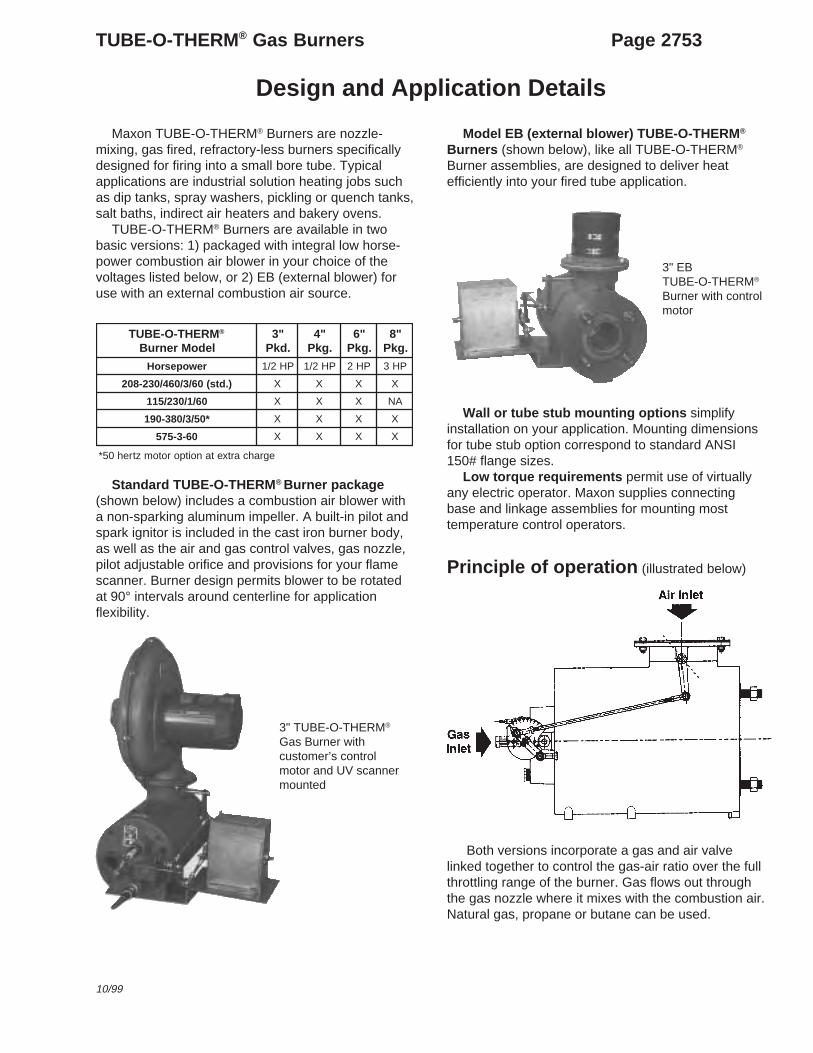
Horizontal mounting of the burner is preferred, butit may be mounted in any position suitable for auto-matic control motor and UV scanner. Do not directlyinsulate tube length outside of tank or overheatingand deterioration of tube may occur. The installershould take precautions to prevent personnel fromcoming into contact with the hot section of the tube.See restrictions in the “Wall Mounting Option” sectionon page 2755.
NOTICE: Burner performance can be affectedby tube configuration. (See page 2755.)
Tube length and configurationTube design should consist of a specified length of
Schedule #40 pipe or lighter (see note below) in thesame size as burner. It is possible to fire TUBE-O-THERM® Burners into tube diameters larger than thesize designation. Contact your Maxon representativefor further information.
Maxon suggests that the first straight pass of tubeconsist of the minimum length shown below for eachtube size and not end in a single-miter elbow turn.Burner capacity may be reduced if tube layout hasmultiple single-miter turns.
Firing tube length and resulting wetted tube surfacearea determines combustion transfer efficiency.Refer to efficiency vs. tube length chart on page2756 for proper length.
Many factors affect overall system efficiency.Typical installations run in the 70% to 80% range.Space considerations (including tube displacement)may limit possible tube lengths and reduce efficiency.Above 80% efficiency, there is a risk of condensation-caused tube damage.
Small bore immersion tubes can be sized for efficien-cies lower than 80% if tank space is limited or if completefreedom from tube condensation is desired.
NOTE: Schedule 40 pipe should be used for atleast the first 2 feet of tube length.
Temperature limitationsBlower motor manufacturers recommend maxi-
mum ambient temperature of +140°F (+40°C).Temperature limits can vary with the type of motorand insulation used. Such special motors are avail-able at net extra charge and with extended deliveries.Check blower motor nameplate for temperature limitson EB TUBE-O-THERM® Burners.
Control motor manufacturers normally establish amaximum ambient temperature for their operators at+125°F (+52°C).
TUBE-O-THERM® Burner internal componentsinclude Rulon bearings which have a maximumtemperature limit of +500°F (+260°C).
Automatic controlRegardless of the type of automatic control (high-
low or modulating), TUBE-O-THERM® Burners shouldbe at or very near the low firing position for pilotignition and main flame light-off.
The built-in air and gas flow control valves aremechanically linked together. At low, the air valve iscracked open but the gas valve is practically closed.
If some higher firing rate is selected for low fire onhigh-low installations, both valves will be openedwider. The increased combustion air will necessitatemore gas for pilot ignition. If carried too far, thisincrease can cause the main flame to be too rich.
Two position control, then, results in what essen-tially is high-low control, down to minimum capacity.
With either high-low or modulating control, high firecan be set at any desired point within burner range.(See notes on instruction page 2750-S-1 for set up ofhigh-fire points less than rated high fire).
The TUBE-O-THERM® Burner was designed toaccept the following electric control motors: Barber-Colman (EA51-58; also with prefix MC, MP, or MF),Honeywell Modutrol (M644, M744, M941, M944,M640A, or M940A), and Penn/Johnson (M80 or M81).The motor mounting bracket and linkage included withTUBE-O-THERM® Burners will accept any of thesemotors; additional CB & L parts are not required.
Flame safeguardThe TUBE-O-THERM® Burner will operate with a
variety of UV scanners for all burner sizes.

TUBE-O-THERM® Gas Burners Page 2755
4/99
Design and Application Details (continued)
Wall mounting optionThe TUBE-O-THERM® Burner was designed to
transfer heat to your process as efficiently as possible.As a result, your process tube, which bolts to theoutlet of the TUBE-O-THERM® Burner, can become hotduring the burner’s operation. The inlet portion of thistube will overheat if it extends too far outside the tank.The maximum recommended length for the inlet portionof your process tube outside the tank is shown asDimension C in the drawings labeled “Stub mountedversions” on pages 2759-2761.
For most applications, the wall mounting optionis recommended. Use of the wall mounting optionwill support the burner off of the tank, instead ofsupporting the burner with the tube. Maxon alsosuggests using a burner support independent of theflange, which will allow for some expansion duringfiring. Consult your Maxon representative for moreinformation.
Tube exhaust requirementsWARNING: Failure to follow the recommendedexhaust considerations could result in poor burnerperformance and/or corrosion of the fired tube due tocondensation.
Historically, conventional immersion tube burnerswere sized for 70% efficiency, since this percentageprovided a compromise between operating fueleconomy and tube length.
Small-bore tubes require less space than conven-tional tubes. Therefore, small-bore tubes can be madelonger to provide efficiencies of 80% or more.
Tubes sized for 80% efficiency will have lowexhaust temperatures, causing condensation to form inthem during start-up or during long idling periods. Thiscondensation will normally evaporate after the burnerhas run at high fire for a brief period of time. If ex-tended idling periods are expected, a condensate drainshould be provided at the low point nearest the exhaustand the immersion tube should be pitched towards theexhaust.
If the immersion tube will operate at efficiencies of75% or lower, the exhaust leg can exit through theliquid surface in the tank without designing for conden-sation. However, the length of the exhaust tube mustalso be considered in the design as explained below.
These considerations also extend to the exhaustlengths after the tube exits the liquid surface. Anexhaust tube exiting the tank will continue to transferheat and cool the products of combustion to theircondensation point. Therefore, an atmospheric break ordilution tee (shown at right) should be used. By doing
Cross-sectional area of the exhaust hood should bea minimum of 1.5 times the fired tube cross-sectional area.
so, the diluting atmospheric air will depress thedewpoint temperature of the combustion products sothat they may exhaust out of the plant without unduecondensation.
If the dilution tee option is chosen, there must besafeguards to ensure that the diluting air is not re-stricted or blocked. If this were to occur, condensationinside the stack could result, with condensate flowingdownward to the low point in the tube, possibly block-ing the tube and causing burner instability.
Because of the high firing rates possible with thisburner and the low cross-sectional area of the tubes,no draft or chimney effect should be designed for, orexpected, if the exhaust stack diameter is equal tothe fired tube diameter.
Immersion tubes are usually vented to the outdoors,except for those in highly ventilated areas such as aplating room with continuous high-volume exhaust. Anexhaust fan may be required if the building is undernegative pressure. Exhaust is normally diluted to avoidthe need for high-temperature fans, but adequatemake-up air must be available.
This diluting can be done with an open tee installedin a vertical run (or in a horizontal run with the openend down), but such a system mixes slowly.
An adjustable hood (shown in sketch below) offersmuch better performance. In all cases, care must betaken that all products of combustion are exhaustedfrom the building.

Page 2756 TUBE-O-THERM® Gas Burners
Design and Application Details (continued)
Immersion Tube Sizing – 60 Hz
Design Notes1. Systems sized for 80% efficiencies or higher need to
account for condensation during extended idlingperiods. Refer to Design and Application Details onpage 2755.
2. Curves shown are for 60 Hz applications only.3. Curves above are not parallel due to small differences in
excess combustion air at maximum design rate. AllTUBE-O-THERM®Burners operate in a range of 2% to4% excess oxygen at maximum firing rate.
4. Use the centerline lengths of elbows when computingtotal tube length.
5. Note that longer tube lengths are required to achieve thesame efficiency on external blower (EB) versions. This is
due to increased maximum firing rate.
Indirect FiringTube sizing chart above is applicable only to liquid-
backed immersion tubes. Indirect-fired applications (non-liquid backed fired tubes) could require additional lengthdepending on the specific application. For indirect firing inmoving air streams, use the above chart and multiplythe specified tube length by 1.75 to obtain the sameefficiency.
Recommended air stream velocity across fired tubesis 1500+ FPM.
80
75
70
65
60
55
50
45
40
35
30
25
20
15
10
Wet
ted
Tub
e Le
ngth
(fee
t)
65
6" EB (3M Btu/hr)
6" Pkg. (2M Btu/hr)
4" EB (1.35M Btu/hr)4" Pkg. (900K Btu/hr)3" EB (750K Btu/hr)
3" Pkg. (500K Btu/hr)
70 75 80 85
Above 80%Design for
Condensation
Immersion Tube Efficiency (percent)
8" EB (5.3M Btu/hr)
8" Pkg. (3.5M Btu/hr)

TUBE-O-THERM® Gas Burners Page 2757
9/03
Capacities and Specifications
60 Hz capacity and specification information forboth standard burners (including blower) and EBburners (requiring separate air supply) are given in thetable on page 2758. Measured sound levels and motorinformation apply only to standard burners.
For operation on 50 Hz power, reduce capacitiesto 83% of those shown. Refer to 50Hz capacities andspecifications on Product Information Sheet 2750-2 forproper operating pressures.
Air pressure readings at test connection reflectthose that may be expected during high fire operationand may vary as a result of tube and exhaust configu-rations.
Inlet air pressures and flows must not exceedthose given in table. DO NOT OVERSIZE blowersfeeding EB Burners. If a blast gate or similar device isused to limit air pressure at an EB Burner, air pressureat the burner will rise as firing rate is reduced until theblower’s rated pressure is reached. This will result inincreased pilot and minimum capacities, as well asincreased excess air at lower firing rates.
For optimum performance, the use of Maxon FGBlowers is recommended.
NOTE: The required combustion air blower foreach individual EB-style burner is given below:
3" Burner C-1450-12 (1-1/2 HP)
4" Burner C-1450-12 (1-1/2 HP)
6" Burner C-3480-12 (3 HP)
8" Burner C-7020-16 (7-1/2 HP)
Blower curves for these burners are shown onProduct Information Sheet 2750-3.
The TUBE-O-THERM® Burner combustion air andfuel gas controls are linked and characterized toprovide proper air/fuel ratios at specific supplypressures. Use of blowers which do not match theMaxon FG Blower performance curves shown onProduct Information Sheet 2750-3 could result inburner instability, excessive rumbling and unsatis-factory overall performance.
Main gas train should be sized to give no morethan 6" wc pressure drop to obtain catalog minimums.It is recommended to size the regulator for at least120% of the full system capacity at the requiredpressure, carefully considering pipe train losses.
Pilot piping and regulator should be sizedcarefully for the full pilot and capacity shown on Page2758. Pilot regulator pressure range should match thepressure range used for the main gas regulator. Thiswill eliminate the possibility of chattering in the pilotregulator when the main gas (higher pressure) is athigh fire and the burner operates with continuous pilot.If burner controls are set to operate with interruptedpilot, chattering would not be a concern.
NOTE: Most regulator manufacturers include aninternal relief valve in their standard regulators. Theserelief valves will begin to vent when the downstreampressure is somewhere around 7 inches w.c. greaterthan the regulator set pressure. Regulators can beordered without an internal vent. The best option is torun the pilot interrupted. If the pilot is not interrupted,catalog minimums cannot be obtained.
Refer to Page 2758 for the proper pilot gas pressureas measured at the burner gas test port. Theadjustable orifice inside the pilot can be used toestablish the required pressure (5/32" hex wrenchrequired). Pilot solenoid should be located within 5 feetof burner to allow gas to reach burner before flamesafeguard “times-out”.
Self-piloting feature of burner allows pilot gas tobypass internal gas control valve and issue from maingas nozzle ports. Most insurance authorities agree thatan interrupted pilot is a more reliable method ofmonitoring an industrial combustion system.
Low-fire start: Main flame light-off is possibleabove minimum fire position, but larger pilot will berequired and turndown will be sacrificed.
seicneiciffErefsnarT
%ycneiciffErefsnarT)htgnelebutnodesab(
tf,rh/utB 2 ecafrusebutdettew).gva(
.gkP"3 BE"3 .gkP"4 BE"4 .gkP"6 BE"6 .gkP"8 BE"8
56 084,53 084,53 038,42 040,13 018,32 042,13 415,62 164,23
07 061,32 092,72 022,12 051,82 035,12 005,82 680,32 043,92
57 008,71 033,22 097,81 018,52 066,91 012,62 731,12 605,72
08 008,41 044,91 022,71 021,42 072,81 027,42 386,91 327,52
58 098,21 004,71 048,51 056,22 002,71 043,32 840,81 136,42

Page 2758 TUBE-O-THERM® Gas Burners
Capacities and Specifications – 60 Hertz
MREHT-O-EBUT ® renruBeziS "3 "4 "6 "8
noitpircseD .dgkPlanretxE
rewolB.dgkP
lanretxErewolB
.dgkPlanretxE
rewolB.dgkP
lanretxErewolB
seiticapaC)rh/utB(
mumixaM 000,005 000,057 000,009 000,053,1 000,000,2 000,000,3 000,005,3 000,003,5
ylnOtoliP 000,05 000,57 000,09 000,531 000,031 000,002 000,053 000,035
)ylnoniam(muminiM 000,05 000,57 000,09 000,531 000,061 000,042 000,053 000,074
saGlarutaNstnemeriuqeR
deriuqererusserpsaGta(renrubniamrof
)seiticapacmumixam
renruboTtelnisag
cw"3.53 cw"0.66 cw"5.92 cw"3.56 cw"5.63 cw"4.67 cw"0.73 cw"67
renruboTtroptsetsag
cw"1.23 cw"0.95 cw"8.52 cw"9.65 cw"2.92 cw"1.26 cw"0.33 cw"27
erusserpsagtoliPderiuqer
renruboTtroptsetsag
cw"6.0 cw"2.1 cw"5.0 cw"0.1 cw"3.0 cw"6.0 cw"6.0 cw"3.1
rianoitsubmoCderiuqererusserp
riarenrubtAtelni
cw"1.6 cw"3.81 cw"2.7 cw"7.61 cw"8.9 cw"6.81 cw"0.01 cw"8.42
laitnereffiDerusserpria
]1[cw"5.1 cw"8.2 cw"3.1 cw"8.2 cw"1.2 cw"9.3 cw"4.1 cw"7.2
saGenaporPstnemeriuqeR
deriuqererusserpsaGta(renrubniamrof
)seiticapacmumixam
renruboTtelnisag
cw"0.51 cw"0.23 cw"5.41 cw"7.13 cw"0.81 cw"0.14 cw"2.81 cw"44
renruboTtroptsetsag
cw"6.31 cw"0.92 cw"9.21 cw"4.82 cw"4.51 cw"7.33 cw"5.61 cw"73
erusserpsagtoliPderiuqer
renruboTtroptsetsag
cw"5.0 cw"1.1 cw"3.0 cw"8.0 cw"4.0 cw"8.0 cw"6.0 cw"3.1
rianoitsubmoCta(deriuqererusserp
onhtiwnoitisoperifhgih)erif
riarenrubtAtelni
cw"1.6 cw"3.81 cw"2.7 cw"0.71 cw"8.9 cw"6.81 cw"0.01 cw"8.42
laitnereffiDerusserpria
]1[cw"5.1 cw"8.2 cw"3.1 cw"8.2 cw"1.2 cw"9.3 cw"4.1 cw"7.2
deriuqeremulovrianoitsubmocmumixaM001MFCS
551MFCS
081MFCS
072MFCS
514MFCS
006MFCS
576MFCS
5101MFCS
htgnelebuT )ycneiciffe%08rofdezis,teefni( dnaretemaid )rethgilroepip04#eludehcS(
fo.tf03.aid"3
fo.tf43.aid"3
fo.tf63.aid"4
fo.tf83.aid"4
fo.tf05.aid"6
fo.tf65.aid"6
fo.tf46.aid"8
fo.tf37.aid"8
rewolbrianoitsubmocro/dnarenrubdegakcaPderiuqerrewopesroh
PH2/1 ]2[ PH2/1 ]2[ PH2 ]2[ PH3 ]3[
sleveldnuosrenrubdegakcaP teef3ta)A(Bd)recnelison(
58 A/N 68 A/N 88 A/N 98 A/N
.6-S-0572dna5-S-0572segapnospiTecivreSnidebircsedsierusserprialaitnereffidgnitteS]1[).7572egapnonoitcelesrewolbdetsegguseeS(deriuqerrewolbiso61]3[deriuqerrewolbiso21]2[
.3-0572teehSnoitamrofnItcudorPnonwohserasevrucrewolB
50 Hz performance data shown on Product Information Sheet 2750-1
TUBE-O-THERM® Gas Burners Page 2759
8/03
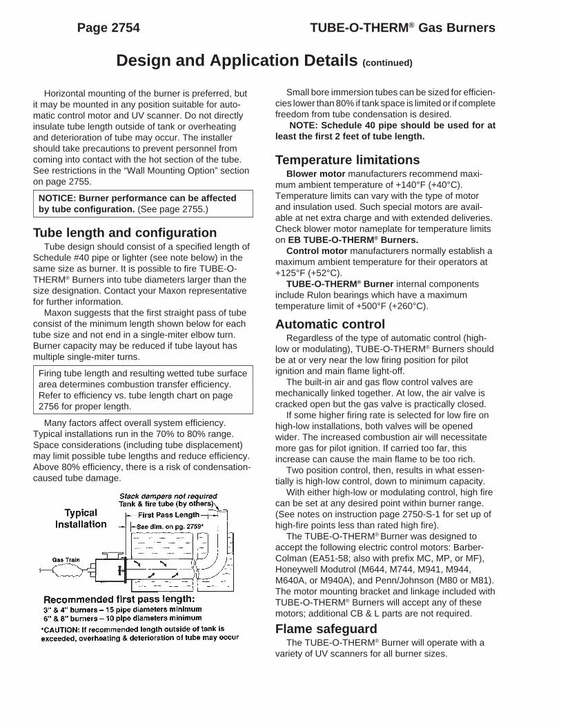
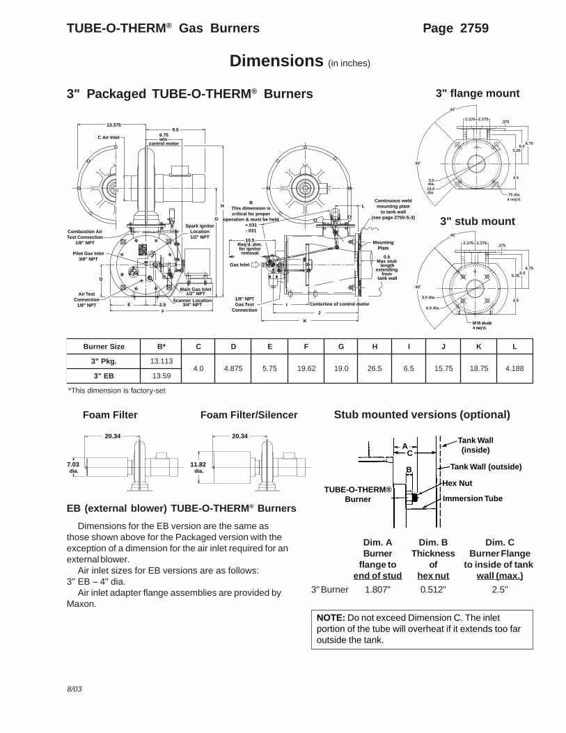
Dimensions (in inches)
3" Packaged TUBE-O-THERM ® Burners
Foam Filter
EB (external blower) TUBE-O-THERM ® Burners
Stub mounted versions (optional)
Dimensions for the EB version are the same asthose shown above for the Packaged version with theexception of a dimension for the air inlet required for anexternal blower.
Air inlet sizes for EB versions are as follows:3" EB – 4" dia.
Air inlet adapter flange assemblies are provided byMaxon.
Dim. A Dim. B Dim. CBurner Thickness Burner Fl ange
flange to of to inside of tankend of stud hex nut wall (max.)
3" Burner 1.807" 0.512" 2.5"
3" flange mount
3" stub mount
eziSrenruB *B C D E F G H I J K L
.gkP"3 311.310.4 578.4 57.5 26.91 0.91 5.62 5.6 57.51 57.81 881.4
BE"3 95.31
tes-yrotcafsinoisnemidsihT*
Foam Filter/Silencer
NOTE: Do not exceed Dimension C. The inletportion of the tube will overheat if it extends too faroutside the tank.
7.03 dia.
20.34 20.34
11.82 dia.
Tank Wall(inside)
Tank Wall (outside)
Hex Nut
Immersion Tube
B
AC
TUBE-O-THERM®Burner
GASGAS
MAXONMAXON
9090
80807070
60605050 4040 3030
20201010
0
LIP OT
TI LL
ASN
EREH
FLAMEFLAME
DETECTORDETECTOR
GAS BURNERGAS BURNER
TUBE-O-THERM
USEUSE
BTU/HRBTU/HR
MILLIONMILLION
CAPACITYCAPACITY
NO.NO.
MUNCIE,INDIANA,U.S.A.MUNCIE,INDIANA,U.S.A.
MAXIMUMMAXIMUM
ASBYASBY
MAXON CORPORATIONMAXON CORPORATION
TUBETUBE
FIRINGFIRING
WITHWITH
FUELFUEL
F.O. NO.F.O. NO.
R%%135R%%135
R%%135R%%135
MAXONMAXON
13.3759.5
6.75w/o
control motorC Air Inlet
G
Spark IgnitorLocation1/2" NPT
Combustion AirTest Connection
1/8" NPT
Pilot Gas Inlet3/8" NPT
Air TestConnection
1/8" NPT
Main Gas Inlet1/2" NPT
2.5EF
D
BThis dimension iscritical for proper
operation & must be held+.031-.031
10.5Req'd. dim.for ignitorremoval
Gas Inlet
1/8" NPTGas Test
ConnectionI
J
K
0.5 Max stub
lengthextending
from tank wall
MountingPlate
Continuous weldmounting plate
to tank wall(see page 2750-S-3)
LH
Scanner Location3/4" NPT Centerline of control motor
6.756.0
5.25
4.5
M16 studsM16 studs4 req'd.4 req'd.
6.0 dia.
3.0 dia.
90˚
45˚
2.3752.375 .375
6.756.0
5.25
4.5
.75 dia4 req'd.
10.0dia.
3.0dia.
90˚
45˚
2.3752.375.375

Page 2760 TUBE-O-THERM® Gas Burners
Dimensions (in inches)
4" Packaged TUBE-O-THERM ® Burners
Foam Filter
EB (external blower) TUBE-O-THERM ® Burners
Stub mounted versions (optional)
Dimensions for the EB version are the same asthose shown above for the Packaged version with theexception of a dimension for the air inlet required for anexternal blower.
Air inlet sizes for EB versions are as follows:4" EB – 4" dia.
Air inlet adapter flange assemblies are provided byMaxon.
Dim. A Dim. B Dim. CBurner Thickness Burner Flange
flange to of to inside of tankend of stud hex nut wall (max.)
4" Burner 1.829" 0.512" 2.5"
4" stub mount
4" flange mount
eziSrenruB *B C D E F G H I J K L
BE&.gkP"4 5.41 0.5 0.6 5.6 83.02 0.12 5.92 0.8 5.71 0.32 260.4
tes-yrotcafsinoisnemidsihT*
Foam Filter/Silencer
NOTE: Do not exceed Dimension C. The inletportion of the tube will overheat if it extends too faroutside the tank.
7.03 dia.
20.34 20.34
11.82 dia.
Tank Wall(inside)
Tank Wall (outside)
Hex Nut
Immersion Tube
B
AC
TUBE-O-THERM®Burner
GASGAS
MAXONMAXON
9090
80807070
60605050 4040 3030
20201010
0
LIP OT
TI LL
ASN
EREH
FLAMEFLAME
DETECTORDETECTOR
GAS BURNERGAS BURNER
TUBE-O-THERM
USEUSE
BTU/HRBTU/HR
MILLIONMILLION
CAPACITYCAPACITY
NO.NO.
MUNCIE,INDIANA,U.S.A.MUNCIE,INDIANA,U.S.A.
MAXIMUMMAXIMUM
ASBYASBY
MAXON CORPORATIONMAXON CORPORATION
TUBETUBE
FIRINGFIRING
WITHWITH
FUELFUEL
F.O. NO.F.O. NO.
R%%135R%%135
R%%135R%%135
MAXONMAXON
13.3759.5
6.75w/o
control motorC Air Inlet
G
Spark IgnitorLocation1/2" NPT
Combustion AirTest Connection
1/8" NPT
Pilot Gas Inlet3/8" NPT
Air TestConnection
1/8" NPT
Main Gas Inlet1/2" NPT
2.5EF
D
BThis dimension iscritical for proper
operation & must be held+.031-.031
10.5Req'd. dim.for ignitorremoval
Gas Inlet
1/8" NPTGas Test
ConnectionI
J
K
0.5 Max stub
lengthextending
from tank wall
MountingPlate
Continuous weldmounting plate
to tank wall(see page 2750-S-3)
LH
Scanner Location3/4" NPT Centerline of control motor
7.56.75
5.9
5.5
11.5 dia.
4.0 dia.
90˚
45˚
2.375 2.375 .375
˚
7.56.755.9
5.5
M16 studs8 required
7.5 dia
4.0 dia
45˚
22.5˚
2.3752.375 .375
TUBE-O-THERM® Gas Burners Page 2761
8/03
Dimensions (in inches)
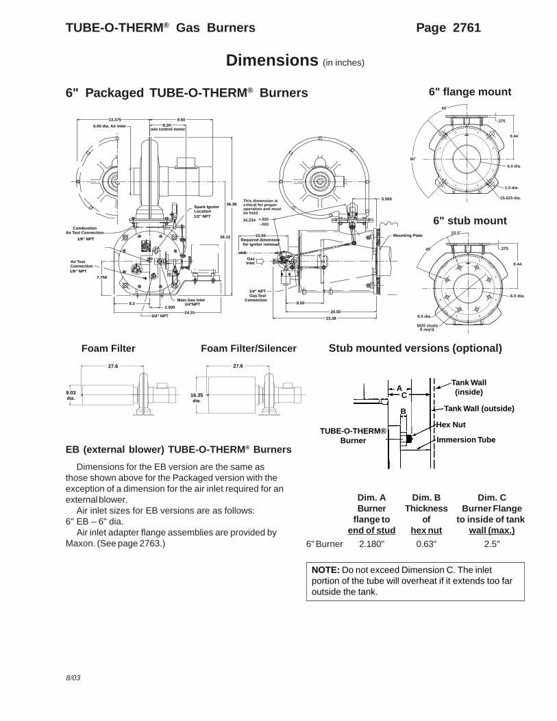
6" Packaged TUBE-O-THERM ® Burners
EB (external blower) TUBE-O-THERM ® Burners
Stub mounted versions (optional)
Dimensions for the EB version are the same asthose shown above for the Packaged version with theexception of a dimension for the air inlet required for anexternal blower.
Air inlet sizes for EB versions are as follows:6" EB – 6" dia.
Air inlet adapter flange assemblies are provided byMaxon. (See page 2763.)
Dim. A Dim. B Dim. CBurner Thickness Burner Fl ange
flange to of to inside of tankend of stud hex nut wall (max.)
6" Burner 2.180" 0.63" 2.5"
Foam Filter Foam Filter/Silencer
9.03dia.
27.6
16.35dia.
27.6
NOTE: Do not exceed Dimension C. The inletportion of the tube will overheat if it extends too faroutside the tank.
Tank Wall(inside)
Tank Wall (outside)
Hex Nut
Immersion Tube
B
AC
TUBE-O-THERM®Burner
GASGAS
MAXONMAXON
9090
80807070
60605050 4040 3030
20201010
0
LIP OT
TI LL
ASN
EREH
FLAME
DETECTOR
GAS BURNER
TUBE-O-THERMTUBE-O-THERM
USEUSE
BTU/HRBTU/HR
MILLIONMILLION
CAPACITYCAPACITY
NO.NO.
MUNCIE,INDIANA,U.S.A.MUNCIE,INDIANA,U.S.A.
MAXIMUMMAXIMUM
ASBYASBY
MAXON CORPORATIONMAXON CORPORATION
TUBETUBE
FIRINGFIRING
WITHWITH
FUELFUEL
F.O. NO.F.O. NO.
R%%135R%%135
R%%135R%%135
MAXONMAXON
5.500
3/4"
6.00 dia. Air Inlet
8.50
15.0026.12
7.750
20.50
23.38
CombustionAir Test Connection
1/8" NPT
8.2
24.31
8.20w/o control motor
Mounting Plate
GasInlet
1/2" NPT
Spark IgnitorLocation
3/4" NPT
NPTMain Gas Inlet
1/8" NPT
Air Test Connection
15.234 +.031-.031
36.38
2.500
13.375 9.50
1/4" NPT Gas Test
Connection
Required dimension for ignitor removal
This dimension is critical for proper operation and mustbe held.
6" stub mount
6" flange mount
15.625 dia.
1.0 dia.
6.0 dia.
9.44
.375
45˚
90˚
M20 studs8 req'd.
9.5 dia.
6.0 dia.
9.44
.375
22.5˚
45˚
Page 2762 TUBE-O-THERM® Gas Burners
Dimensions (in inches)
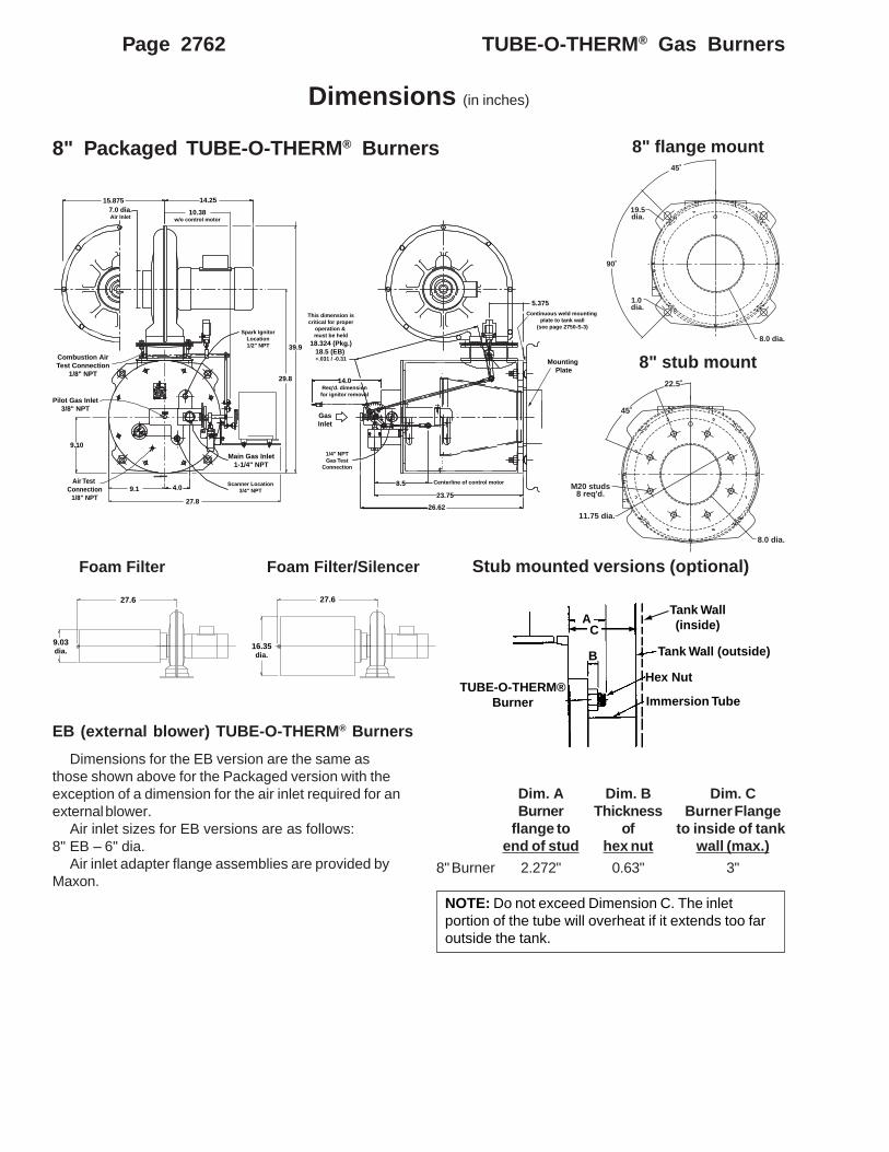
8" Packaged TUBE-O-THERM ® Burners
EB (external blower) TUBE-O-THERM ® Burners
Stub mounted versions (optional)
Dimensions for the EB version are the same asthose shown above for the Packaged version with theexception of a dimension for the air inlet required for anexternal blower.
Air inlet sizes for EB versions are as follows:8" EB – 6" dia.
Air inlet adapter flange assemblies are provided byMaxon.
Dim. A Dim. B Dim. CBurner Thickness Burner Flange
flange to of to inside of tankend of stud hex nut wall (max.)
8" Burner 2.272" 0.63" 3"
Foam Filter Foam Filter/Silencer
9.03dia.
27.6
16.35dia.
27.6
NOTE: Do not exceed Dimension C. The inletportion of the tube will overheat if it extends too faroutside the tank.
Tank Wall(inside)
Tank Wall (outside)
Hex Nut
Immersion Tube
B
AC
TUBE-O-THERM®Burner
E1%%136E1%%136E3%%136E3%%136
9090
80807070
60605050 4040 3030
20201010
0
GAS BURNERGAS BURNER
TUBE-O-THERMTUBE-O-THERM
USEUSE
BTU/HRBTU/HR
MILLIONMILLION
CAPACITYCAPACITY
NO.NO.
MUNCIE,INDIANA,U.S.A.MUNCIE,INDIANA,U.S.A.
MAXIMUMMAXIMUM
ASBYASBY
MAXON CORPORATIONMAXON CORPORATION
TUBETUBE
FIRINGFIRING
WITHWITH
FUELFUEL
F.O. NO.F.O. NO.
R%%135R%%135
R%%135R%%135
MAXONMAXON
LIP OT
TI LL
ASN
EREH
FLAMEFLAME
DETECTORDETECTOR
7.0 dia.Air Inlet
15.875
10.38w/o control motor
14.25
Spark IgnitorLocation1/2" NPT
29.8
39.9Combustion AirTest Connection
1/8" NPT
Pilot Gas Inlet3/8" NPT
Air Test Connection
1/8" NPT
Scanner Location3/4" NPT
Main Gas Inlet1-1/4" NPT
4.09.1
27.8
This dimension iscritical for proper
operation & must be held
18.324 (Pkg.)18.5 (EB) +.031 / -0.31
14.0Req'd. dimensionfor ignitor removal
GasInlet
1/4" NPTGas Test
Connection
Centerline of control motor8.5
23.75
26.62
Mounting Plate
Continuous weld mounting plate to tank wall
(see page 2750-S-3)
5.375
9.10
8" stub mount
8" flange mount
8.0 dia.
1.0 dia.
19.5dia.
45˚
90˚
8.0 dia.
11.75 dia.
M20 studs8 req'd.
45˚
22.5˚
Dimensions (in inches)
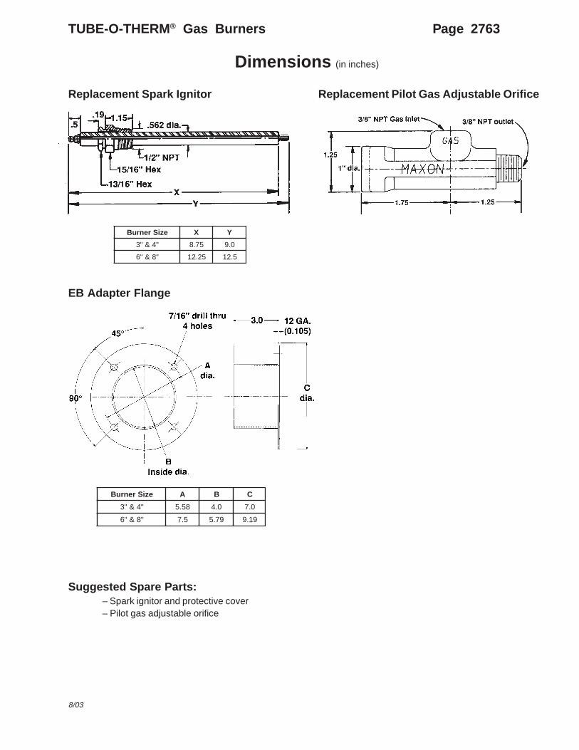
Replacement Pilot Gas Adjustable OrificeReplacement Spark Ignitor
EB Adapter Flange
Suggested Spare Parts:– Spark ignitor and protective cover– Pilot gas adjustable orifice
eziSrenruB X Y
"4&"3 57.8 0.9
"8&"6 52.21 5.21
eziSrenruB A B C
"4&"3 85.5 0.4 0.7
"8&"6 5.7 97.5 91.9
TUBE-O-THERM® Gas Burners Page 2763
8/03
Page 2764 TUBE-O-THERM® Gas Burners
Notes