Phased Array Inspections of Low Pressure Steam Turbine blade Curved Roots
Upload
ijripublishers-ijriCategory
view
434download
4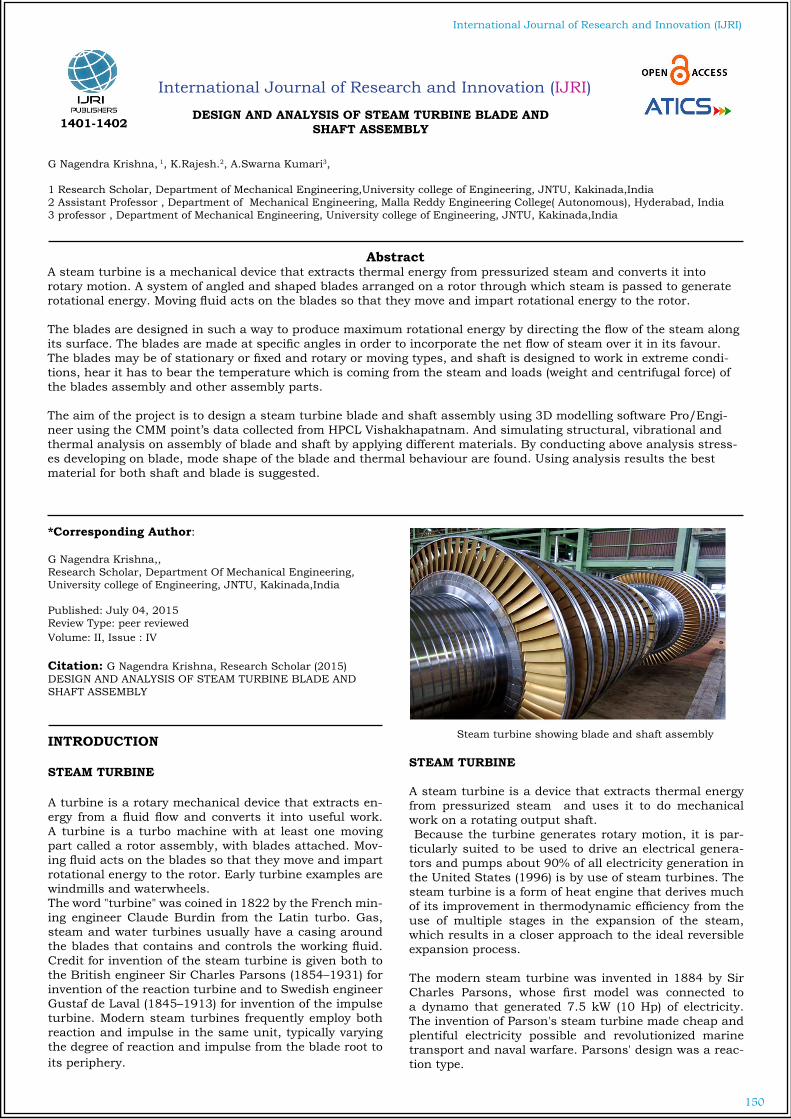
150
International Journal of Research and Innovation (IJRI)
International Journal of Research and Innovation (IJRI)
DESIGN AND ANALYSIS OF STEAM TURBINE BLADE AND SHAFT ASSEMBLY
G Nagendra Krishna, 1, K.Rajesh.2, A.Swarna Kumari3,
1 Research Scholar, Department of Mechanical Engineering,University college of Engineering, JNTU, Kakinada,India2 Assistant Professor , Department of Mechanical Engineering, Malla Reddy Engineering College( Autonomous), Hyderabad, India3 professor , Department of Mechanical Engineering, University college of Engineering, JNTU, Kakinada,India
*Corresponding Author:
G Nagendra Krishna,, Research Scholar, Department Of Mechanical Engineering, University college of Engineering, JNTU, Kakinada,India
Published: July 04, 2015Review Type: peer reviewedVolume: II, Issue : IV
Citation: G Nagendra Krishna, Research Scholar (2015) DESIGN AND ANALYSIS OF STEAM TURBINE BLADE AND SHAFT ASSEMBLY
INTRODUCTION
STEAM TURBINE
A turbine is a rotary mechanical device that extracts en-ergy from a fluid flow and converts it into useful work. A turbine is a turbo machine with at least one moving part called a rotor assembly, with blades attached. Mov-ing fluid acts on the blades so that they move and impart rotational energy to the rotor. Early turbine examples are windmills and waterwheels.The word "turbine" was coined in 1822 by the French min-ing engineer Claude Burdin from the Latin turbo. Gas, steam and water turbines usually have a casing around the blades that contains and controls the working fluid. Credit for invention of the steam turbine is given both to the British engineer Sir Charles Parsons (1854–1931) for invention of the reaction turbine and to Swedish engineer Gustaf de Laval (1845–1913) for invention of the impulse turbine. Modern steam turbines frequently employ both reaction and impulse in the same unit, typically varying the degree of reaction and impulse from the blade root to its periphery.
Steam turbine showing blade and shaft assembly
STEAM TURBINE A steam turbine is a device that extracts thermal energy from pressurized steam and uses it to do mechanical work on a rotating output shaft. Because the turbine generates rotary motion, it is par-ticularly suited to be used to drive an electrical genera-tors and pumps about 90% of all electricity generation in the United States (1996) is by use of steam turbines. The steam turbine is a form of heat engine that derives much of its improvement in thermodynamic efficiency from the use of multiple stages in the expansion of the steam, which results in a closer approach to the ideal reversible expansion process.
The modern steam turbine was invented in 1884 by Sir Charles Parsons, whose first model was connected to a dynamo that generated 7.5 kW (10 Hp) of electricity. The invention of Parson's steam turbine made cheap and plentiful electricity possible and revolutionized marine transport and naval warfare. Parsons' design was a reac-tion type.
AbstractA steam turbine is a mechanical device that extracts thermal energy from pressurized steam and converts it into rotary motion. A system of angled and shaped blades arranged on a rotor through which steam is passed to generate rotational energy. Moving fluid acts on the blades so that they move and impart rotational energy to the rotor. The blades are designed in such a way to produce maximum rotational energy by directing the flow of the steam along its surface. The blades are made at specific angles in order to incorporate the net flow of steam over it in its favour. The blades may be of stationary or fixed and rotary or moving types, and shaft is designed to work in extreme condi-tions, hear it has to bear the temperature which is coming from the steam and loads (weight and centrifugal force) of the blades assembly and other assembly parts.
The aim of the project is to design a steam turbine blade and shaft assembly using 3D modelling software Pro/Engi-neer using the CMM point’s data collected from HPCL Vishakhapatnam. And simulating structural, vibrational and thermal analysis on assembly of blade and shaft by applying different materials. By conducting above analysis stress-es developing on blade, mode shape of the blade and thermal behaviour are found. Using analysis results the best material for both shaft and blade is suggested.
1401-1402
151
International Journal of Research and Innovation (IJRI)
CLASSIFICATION OF STEAM TURBINESBY THE ACTION OF STEAM1. Impulse 2. Reaction 3. Impulse and reaction combinedTHE NUMBER OF STEP REDUCTIONS INVOLVED1. Single stage 2. Multi-stage THE DIRECTION OF STEAM FLOW1. Axial 2. Radial 3. Mixed 4. Tangential THE INLET STEAM PRESSURE1. High pressure 2. Medium pressure 3. Low pressure THE FINAL PRESSURE1. Condensing 2. Non-condensing THE SOURCE OF STEAM3. Extraction4. reheat
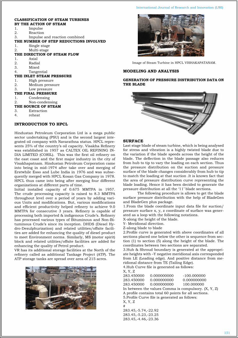
INTRODUCTION TO HPCL
Hindustan Petroleum Corporation Ltd is a mega public sector undertaking (PSU) and is the second largest inte-grated oil company with Navarathna status. HPCL repre-sents 25% of the country’s oil capacity. Visakha Refinery was established in 1957 as CALTEX OIL REFINING IN-DIA LIMITED (CORIL). This was the first oil refinery on the east coast and the first major industry in the city of Visakhapatnam. Hindustan Petroleum Corporation came into being in mid-1974 after take over and merging of Erstwhile Esso and Lube India in 1976 and was subse-quently merged with HPCL Kosan Gas Company in 1978. HPCL thus came into being after merging four different organizations at different parts of time.Initial installed capacity of 0.675 MMTPA in 1957. The crude processing capacity is raised to 8.3 MMTPA throughout level over a period of years by adding vari-ous Units and modifications. But, various modifications and efficient productivity helped refinery to achieve 9.0 MMTPA for consecutive 3 years. Refinery is capable of processing both imported & indigenous Crude’s. Refinery has processed various types of Bituminous and Non-Bi-tuminous Crude’s since its inception. DHDS (Diesel Hy-dro-Desulphurization) and related utilities/offsite facili-ties are added for enhancing the quality of diesel product to meet Environment norms. Similarly, MS (motor spirit) block and related utilities/offsite facilities are added for enhancing the quality of Petrol product. VR has its additional storage facilities at the North of the refinery called as additional Tankage Project (ATP). The ATP storage tanks are spread over area of 215 acres.
Image of Steam Turbine in HPCL VISHAKAPATANAM.
MODELING AND ANALYSIS
GENERATION OF PRESSURE DISTRIBUTION DATA ON THE BLADE
SURFACELast stage blade of steam turbine, which is being analysed for stress and vibration is a highly twisted blade due to the variation if the blade speeds across the height of the blade. The deflection in the blade passage also reduces from hub to tip to vary the loading on each section. Thus the pressure distribution on the suction and pressure surface of the blade changes considerably from hub to tip to match the loading at that suction .It is known fact that the area of pressure distribution curve representing the blade loading. Hence it has been decided to generate the pressure distribution at all the ‘11’ blade sections. The following procedure is allows to get the blade surface pressure distribution with the help of BladeGen and BladeGen plus package.1.From the blade coordinate input data file for suction/pressure surface x, y, z coordinate of surface was gener-ated as a loop with the following notations.X-along the height of the blade.Y- Meridional direction.Z-along blade to blade2.Profile curve is generated with above coordinates of all sections placed one below the other is sequence from sec-tion (1) to section (5) along the height of the blade. The coordinates between two sections are separated.3.Hub & Shroud boundary is generated at the appropri-ate heights with –Y negative meridional axis corresponded from LE (Leading edge). And positive distance from me-ridional distance from TE (Tailing Edge).4.Hub Curve file is generated as follows:X, Y, Z283.450000 0.000000000 -100.000000283.450000 0.000000000 0.000000000283.450000 0.000000000 100.000000 In between the values Comma is compulsory. (X, Y, Z)A profile contains total 60 points for all sections.5.Profile Curve file is generated as follows:X, Y, Z #283.45,-5.74,-22.92283.45,-5.23,-23.25283.45,-4.46,-23.36

152
International Journal of Research and Innovation (IJRI) 283.45,-3.43,-23.22283.45,-2.15,-22.82283.45,-0.66,-22.12283.45, 1.03,-21.11283.45, 2.85,-19.72283.45, 4.74,-17.91283.45, 6.61,-15.62283.45, 8.32,-12.78283.45, 9.66,-9.39283.45, 10.4,-5.53283.45, 10.35,-1.43#442.65, 15.21,-15.51442.65, 15.64,-15.21442.65, 15.81,-14.69442.65, 15.74,-13.95442.65, 15.44,-12.99442.65, 14.91,-11.83442.65, 14.19,-10.49442.65, 13.26,-8.99442.65, 12.14,-7.36442.65, 10.79,-5.66442.65, 9.23,-3.95
BLADE PROFILE
Turbine blade profile in Pro/E Sketcher.
Generated part of Blade
Image showing blade assembly.
Generated part of shaft.
Step by steps procedure for Assembly:•After opening new assembly file shaft is assembled with default constraints.•Patterned blade part is assembled using insert, mate and align constraints at required positions •File is exported to IGES( Initial Graphical Exchanging Specification) for analysis purpose
Turbine blade and shaft assembly
Now using these design conditions and working condi-tions of the turbine. The structural, vibrational and ther-mal analysis is carried out with three different materials as mentioned. The temperature changes in the turbine are monitored periodically using the thermal images taken by the thermal camera. When a image taken by the thermal camera the image will show the temperature variations directly

153
International Journal of Research and Innovation (IJRI)
INTRODUCTION TO FEA
Finite Element Analysis (FEA) was first developed in 1943 by R. Courant, who utilized the Ritz method of numerical analysis and minimization of variational calculus to ob-tain approximate solutions to vibration systems. Shortly thereafter, a paper published in 1956 by M. J. Turner, R. W. Clough, H. C. Martin, and L. J. Topp established a broader definition of numerical analysis. The paper cen-tered on the "stiffness and
RESULTS AND DISCUSSION
When the simulation is completed a report is generated in order to explore the results. At first the static analy-sis is done for three different types of materials. It gives stresses developed in the turbine blade and shaft assem-bly, strain values and displacement.Now all the stress, strain and displacement values are shown in figures below.
RESULTS OF STRUCTURAL ANALYSIS
Stress developed in EN24 Stainless Steel
Displacement of EN24 Stainless Steel.
Strain for EN24 Stainless Steel.
AISI 4130 Steel
Stress developed in AISI 4130 Steel
Displacement of AISI 4130 Steel
Strain for AISI 4130 Steel.
Thermal gradient for ZAMAK
Thermal flux for ZAMAK.
154
International Journal of Research and Innovation (IJRI) RESULT TABLES AND GRAPHS
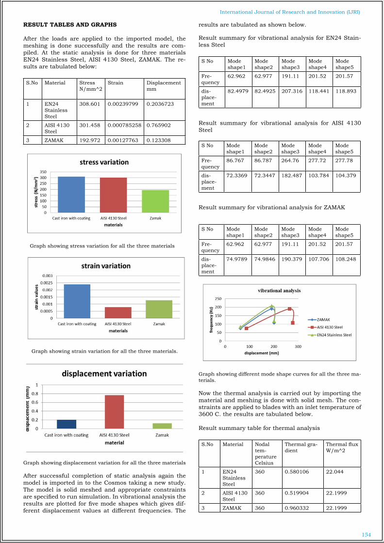
After the loads are applied to the imported model, the meshing is done successfully and the results are com-piled. At the static analysis is done for three materials EN24 Stainless Steel, AISI 4130 Steel, ZAMAK. The re-sults are tabulated below:
S.No Material StressN/mm^2
Strain Displacementmm
1 EN24 Stainless Steel
308.601 0.00239799 0.2036723
2 AISI 4130 Steel
301.458 0.000785258 0.765902
3 ZAMAK 192.972 0.00127763 0.123308
Graph showing stress variation for all the three materials
Graph showing strain variation for all the three materials.
Graph showing displacement variation for all the three materials
After successful completion of static analysis again the model is imported in to the Cosmos taking a new study. The model is solid meshed and appropriate constraints are specified to run simulation. In vibrational analysis the results are plotted for five mode shapes which gives dif-ferent displacement values at different frequencies. The
results are tabulated as shown below.
Result summary for vibrational analysis for EN24 Stain-less Steel
S No Mode shape1
Mode shape2
Mode shape3
Mode shape4
Mode shape5
Fre-quency
62.962 62.977 191.11 201.52 201.57
dis-place-ment
82.4979 82.4925 207.316 118.441 118.893
Result summary for vibrational analysis for AISI 4130 Steel
S No Mode shape1
Mode shape2
Mode shape3
Mode shape4
Mode shape5
Fre-quency
86.767 86.787 264.76 277.72 277.78
dis-place-ment
72.3369 72.3447 182.487 103.784 104.379
Result summary for vibrational analysis for ZAMAK
S No Mode shape1
Mode shape2
Mode shape3
Mode shape4
Mode shape5
Fre-quency
62.962 62.977 191.11 201.52 201.57
dis-place-ment
74.9789 74.9846 190.379 107.706 108.248
Graph showing different mode shape curves for all the three ma-terials.
Now the thermal analysis is carried out by importing the material and meshing is done with solid mesh. The con-straints are applied to blades with an inlet temperature of 3600 C. the results are tabulated below.
Result summary table for thermal analysis
S.No Material Nodal tem-perature Celsius
Thermal gra-dient
Thermal fluxW/m^2
1 EN24 Stainless Steel
360 0.580106 22.044
2 AISI 4130 Steel
360 0.519904 22.1999
3 ZAMAK 360 0.960332 22.1999

155
International Journal of Research and Innovation (IJRI)
Graph showing nodal temperature variation for all the three ma-terials
Graph showing thermal gradient variation for all the three ma-terials
Graph showing thermal flux variation for all the three materials
CONCLUSIONS
The entire project work is done in R&D department of HPCL Visakhapatnam for optimizing the material of steam turbine assembly. A PT2001 turbodine steam turbine is optimized for to re-duce maintenance. Initially static and thermal conditions are evaluated using Infra-red thermometer and digital vi-brometer. Those readings are taken for simulation inputsA FEA model is developed according to given drawing.Static analysis is carried out on FE model using EN24 Stainless steel (present material), AISI 4130 Stainless Steel and zinc aluminum alloy (zamak) with zirconia coat-ing. In static analysis, the stress value of ZAMAK is best when compared with other materials and value is 192.972 N/mm2. The strain value of AISI 4130 Steel is best with a value of 0.000785258. the displacement for ZAMAK is 0.123308.Vibrational analysis is carried out to determine the vibra-tions due to geometry and property of material.In vibrational analysis, ZAMAK is having less displace-ment at a particular frequencies among all the three ma-terials as shown in the table 5.5Thermal analysis is carried out to determine the thermal
behavior like thermal gradient and heat flux.In thermal analysis, ZAMAK is having high thermal gradi-ent and thermal flux and the thermal gradient is 0.960332 oC/cm and thermal flux is 22.1999 W/m2.Partially stabilized zirconia is mainly used as a surface coating to prevent the thermal effect on surface and also it reduces the corrosive effect.As per the analytical results ZAMAK material along with partially stabilized zirconia coating will improve reliability of turbine shaft and blades due to less stress, negligible displacement and strain values, also ZAMAK is having good level of thermal gradient(heat transfer rate) and suf-ficient heat flux rate which in turn improves the power generation rate by reducing the maintenance.
SCOPE OF FUTURE WORK
In this project the total work is carried out to design and analysis of steam turbine blade and shaft assembly by applying different materials and finally suggesting best material for blade and shaft. The future scope of this pro-ject would be designing of turbine blade with different angles and shapes to get more outputs. The new materi-als can be applied to blade and shaft assembly which can reduce maintenance cost and greater power generation without loss.
REFERENCES
1“Speed Controller Design For Steam Turbine”, RekhaRa-jan, MuhammedSalih. P, N. Anilkumar, PG Students [I&C], Dept. of EEE, MES College of Engineering, Kuttip-puram, Kerala, India.
2.“3D Finite Element Structural Analysis of Attachments of Steam Turbine Last Stage Blades”, Alexey I. Borovkov Alexander V. Gaev Computational Mechanics Laboratory, St.Petersburg State Polytechnical University, Russia.
3.“Design of a Constant Stress Steam Turbine Rotor Blade”, Asst. Prof. Dr.ArkanKh. Husain Al-Tai, Mechani-cal Engineering Department, University of Technology, Baghdad, Iraq.
4.“Simulation Modeling Practice and Theory”, Ali Chai-bakhsh, Ali Ghaffari Department of Mechanical Engineer-ing, K.N. Toosi University of Technology.
5.“Development of New High Efficiency Steam Turbine”, EIICHIRO WATANABE, YOSHINORI TANAKA.
6.”Theoretical and Numerical Analysis of the Mechanical Erosion in Steam Turbine Blades”, Fernando Rueda Mar-tínez, Miguel Toledo Velázquez, Juan Abugaber Francis.
7.”Design Optimization and Static & Thermal Analysis of Gas Turbine Blade”, GantaNagaraju , Venkata Ramesh Mamilla, M.V.Mallikarjun.
8.”Analysis of Liquid Droplet Erosion for Steam Tur-bine Blades of Composite Material”, SandeepSoni.
9.Applied thermodynamics by R.K.Rajput.
10.Steam and Gas Turbines and power plant engineering by Dr.R.Yadav.
11.The finite Element Methodology, SINGIRESU S.RAO.
12.SolidWorks 2013 for Engineers and Designers by Prof. Shaun Tickeo & Sandeep Prandas.

156
International Journal of Research and Innovation (IJRI)
AUTHOR
G Nagendra KrishnaResearchScholar,Department of Mechanical Engineering,University college of Engineering, JNTU, Kakinada,India
K.Rajesh,Assistant Professor, Department of Mechanical Engineering, Mallareddy Engineering College( Autonomous),Hyderabad,India
Experience: Industrial 2 years Teaching: 7.5 years
Dr.A.Swarna Kumari3,professor ,Department of Mechanical Engineering,Universitycollege of Engineering, JNTU, Kakinada,India
Experience: Teaching: 24 years