Design and Analysis of Multiplate Clutch Final
16
1 | Page Design & Analysis of Multiplate Clutch A Project Report By Sreetam Bhaduri In partial fulfillment of the requirements for the certificate of the CREO Parametric 2.0 in Signature of Instructor Vinoth Kumar Signature of Technical Leader Signature of Branch Manager Mr. N. Aravanan Mr. R. Charles Immanuel Date: 24/07/2016
-
Upload
sreetam-bhaduri -
Category
Documents
-
view
74 -
download
1
Transcript of Design and Analysis of Multiplate Clutch Final

1 | P a g e
Design & Analysis of Multiplate Clutch
A Project Report
By
Sreetam Bhaduri
In partial fulfillment of the requirements for the certificate of the CREO Parametric 2.0 in
Signature of Instructor
Vinoth Kumar
Signature of Technical Leader Signature of Branch Manager
Mr. N. Aravanan Mr. R. Charles Immanuel
Date: 24/07/2016

2 | P a g e
Contents
S.No. Topics Pg. No.
1. Introduction of CREO Parametric 2.0 3-5
2. Brief Description of Multiplate Clutch 6-6
3. Rendered View & Analysis Result 7-14
4. Bill of Material 15-15
5. Conclusion 16-16
6. Acknowledgement 16-16

3 | P a g e
Introduction of CREO Parametric 2.0
CREO Parametric 2.0 is a commercial CAD/CAM package that is widely used in industry for CAD/CAM applications. It is one of the new generation of systems that not only a full
3-D solid modeler, in contrast to purely 2-D and surface modelers, but also parametric functionality and full associativity. This means that explicit relationships can be established between
design variables and changes can be made at any point in the modelling process and the whole model is updated. The method of constructing a model of an object is very similar to that
followed in the production of a physical component. For example the manufacture of the shaped block would start with the choice of construction environment, the selection of a piece of
stock material followed by a series of manufacturing processes, e.g. milling, drilling, welding/sticking. CREO has direct analogues for most of these operations as various types of features
which can be combined to generate a complete representation of a PART, CREO’s terminology for a single component. Features fall into three main categories, Construction, Sketched and
Pick/Placed.
Features:
Construction Features:-
These features are purely used as an aid to the construction of the part, a number of various forms are available the most commonly used are as follows:
Coordinate systems which aid in the orientation of additional features and the assembly of the part in to subsequent assemblies. Co-ordinate system feature is normally the first
feature in a part definition and is used as the basis for the placement of all subsequent features. Datum are an extension of the idea of construction lines as used on a traditional
drawing. The most used type is a DATUM PLANE which allows a 2-D reference plane to be defined in space. Additional forms include DATUM AXES, DATUM POINTS and
DATUM CURVES. It is normal to add three.

4 | P a g e
DEFAULT datum planes, immediately after the initial coordinate system, to effectively generate default x-y, x-z and y-z planes.
Sketched Features:-
These features are so named because they all involve the use of the SKETCHER mode within CREO. The main features that use this functionality are:
Protrusion using this feature material can be added to/removed from a part by sketching a cross-section and then extruding/revolving/sweeping the section to produce a 3-D
solid/cut. A solid protrusion is normally the first non-constructional feature in a part, and is used to produce the base solid entity of the part. In the material removal mode the action
is similar to a turning, saw or milling cut.
Rib allows the user to produce a thin rib or web. This is a limited version of the protrusion function.
Pick & Place Features:-
Pick and place features tend to refer to simple or standard operations, e.g. the production of HOLES, ROUNDS and CHAMFERS. The action to produce the required effect
has been preprogrammed into CREO, thus requiring the user to indicate the position of the operation on the existing model.

5 | P a g e
Sketcher:-
Central to the use of the `sketched' features is the use of the sketcher or sketch mode. This is basically a 2-D drawing program which allows profiles to be drawn that are
subsequently extruded/revolved/swept etc. through 3-D space to modify the item being constructed. Built into the package is knowledge of how things are typically constructed, e.g.
lines are often parallel, similarly sized sketched entities are likely to be identical. The system uses these `Assumptions' to apply Ove ridable `Constraints' to the sketch, e.g.
vertical/horizontal line, to simplify the drawing the problem. It should be noted that the assumptions taken by the system are partial dependent on the screen scale.
Sketching Tools:
The sketcher has many commands/functions that are accessible either from the SKETCH pull-down menu, via the side icon bar or from context sensitive coating menus accessed via
the RMB. In addition a number are mapped to standard CUED hotkey sequences, described below.
The main drawing commands are found in the following sum-menus:
GEOMETRY: Mouse Sketch, Lines, Arc, Circle, Rectangle and Point.
GEOMETRY TOOLS: Intersect, Trim, Divide, Use edge, Mirror and Move.
SECONDARY INFORMATION: Information about the sketched entities, including intersect and tangent points, angles, distances etc.
Sketcher Assumptions:
The knowledge model underpinning both operational modes attempts to apply constraints based on the following assumptions about the users intent:
Equal radii and diameters, symmetry, horizontal and vertical lines, parallel and perpendicular lines, tangency, 90 and 180 degrees arcs, collinearity, equal segment lengths, point
entities lying on other entities, and centers lying on same horizontal or vertical. More detailed information on these assumptions can be found in the user manuals.

6 | P a g e
Brief Description of Multiplate Clutch
The clutch is a mechanical device, which is used to connect or disconnects the source of power from the remaining parts of the power transmission system at the will of operator. The
clutch can connect or disconnect the driving shaft and driven shaft. An automotive clutch can permit the engine to run without driving the car. This is desirable when the engine is to be
started or stopped, or when the gears to be shifted. Clutch is a mechanism for transmitting rotation, which can be engaged and disengaged. The clutch connects the two shafts so that they
can either be locked together and spin at the same speed (engaged), or be decoupled and spin at different speeds (disengaged). Depending on the orientation, speeds, material, torque
produced and finally the use of the whole device, different kinds of clutches are used. The clutch in itself is a mechanism, which employs different configurations. The friction clutch is an
important component of any automotive machine. It is a link between engine and transmission system which conducts power, in form of torque, from engine to the gear assembly. When
vehicle is started from standstill clutch is engaged to transfer torque to the transmission; and when vehicle is in motion clutch is first disengaged of the drive to allow for gear selection and
then again engaged smoothly to power the vehicle. Generally there are two types of clutches based on type of contact
Positive clutch
Friction clutch
Multi plate clutch comes under the category of friction clutch. Multi plate clutch is an extension of single plate type where the number of friction and metal plates is increased. The
increases in the number of friction surfaces obviously increase capacity of clutch to transmit torque, the size remaining fixed. Alternatively, the overall diameter of clutch is reduced for the
same torque transmission as a single plate clutch. This type of clutch is, therefore used in some heavy transport vehicles and racing cars where high torque is to be transmitted. Besides, this
finds application in case of scooters and motorcycles, where space available is limited.
Desirable properties for friction materials for clutches:
The two materials in contact must have a high coefficient of friction.
The materials in contact must resist wear effects, such as scoring, galling, and ablation.
The friction value should be constant over a range of temperatures and pressures. The materials should be resistant to the environment (moisture, dust, pressure).
The materials should possess good thermal properties, high heat capacity, good thermal conductivity, withstand high temperatures able to withstand high contact pressures
Good shear strength to transferred friction forces to structure.
7 | P a g e
Rendered View & Analysis Result
Exploded View:
8 | P a g e
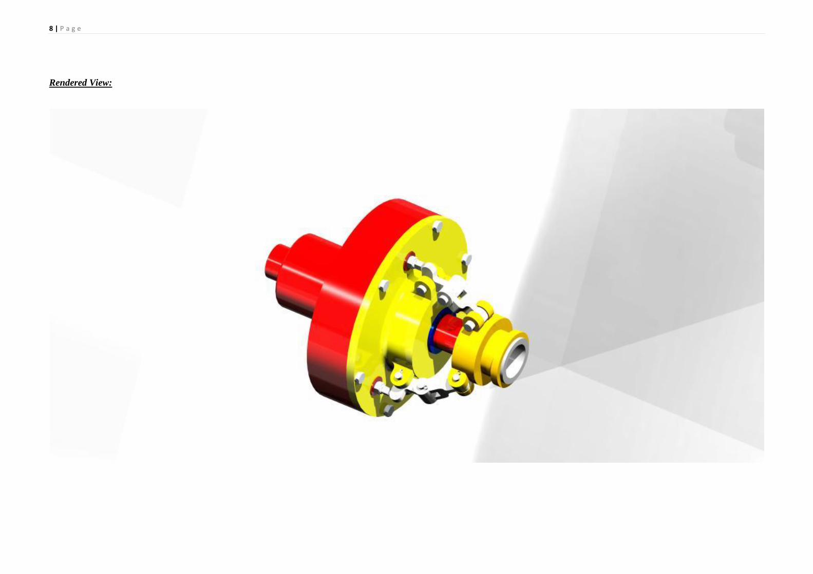
Rendered View:
9 | P a g e
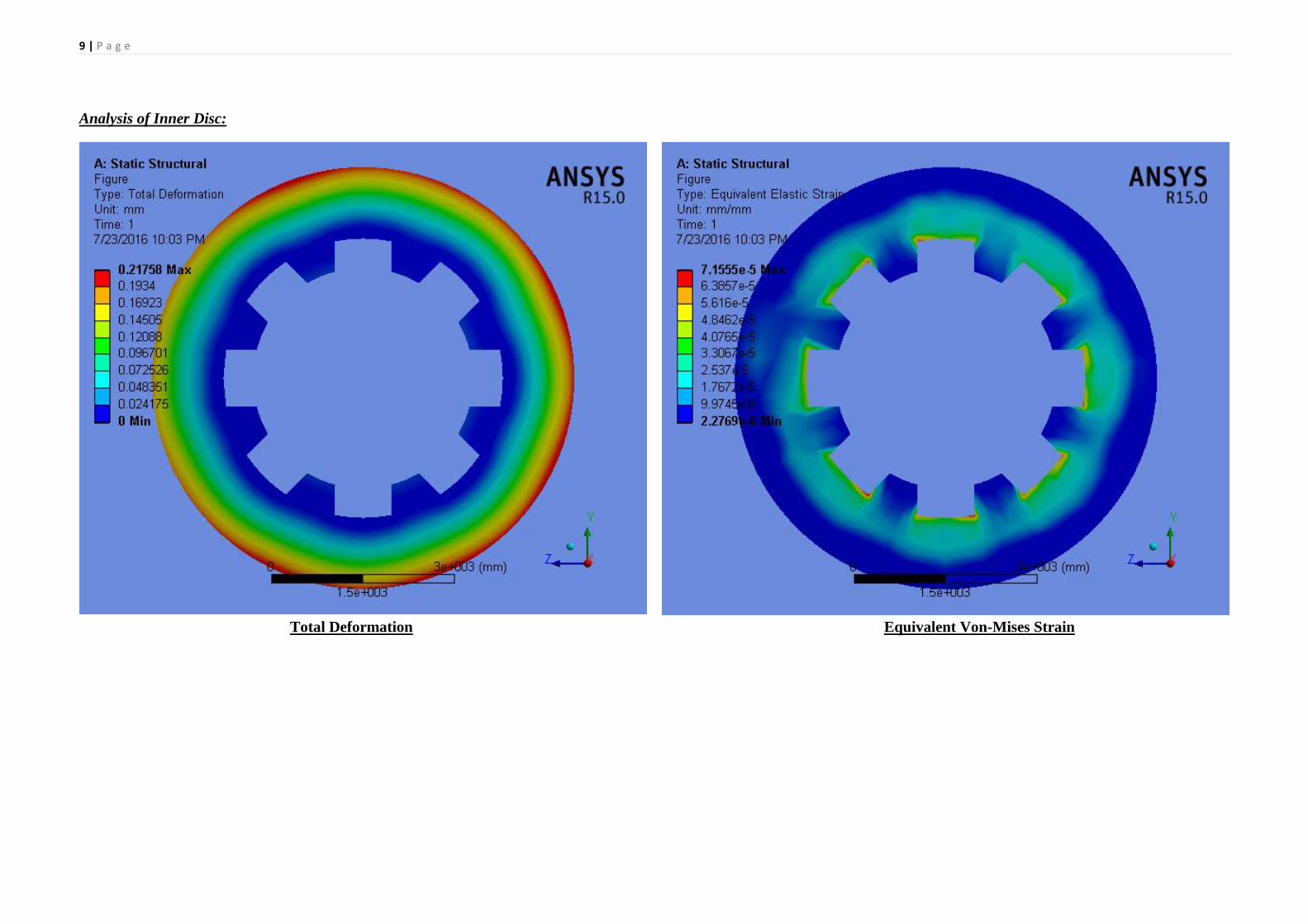
Analysis of Inner Disc:
Total Deformation Equivalent Von-Mises Strain

10 | P a g e
Equivalent Von-Mises Stress Factor of Safety

11 | P a g e
Strain Energy Induced
12 | P a g e
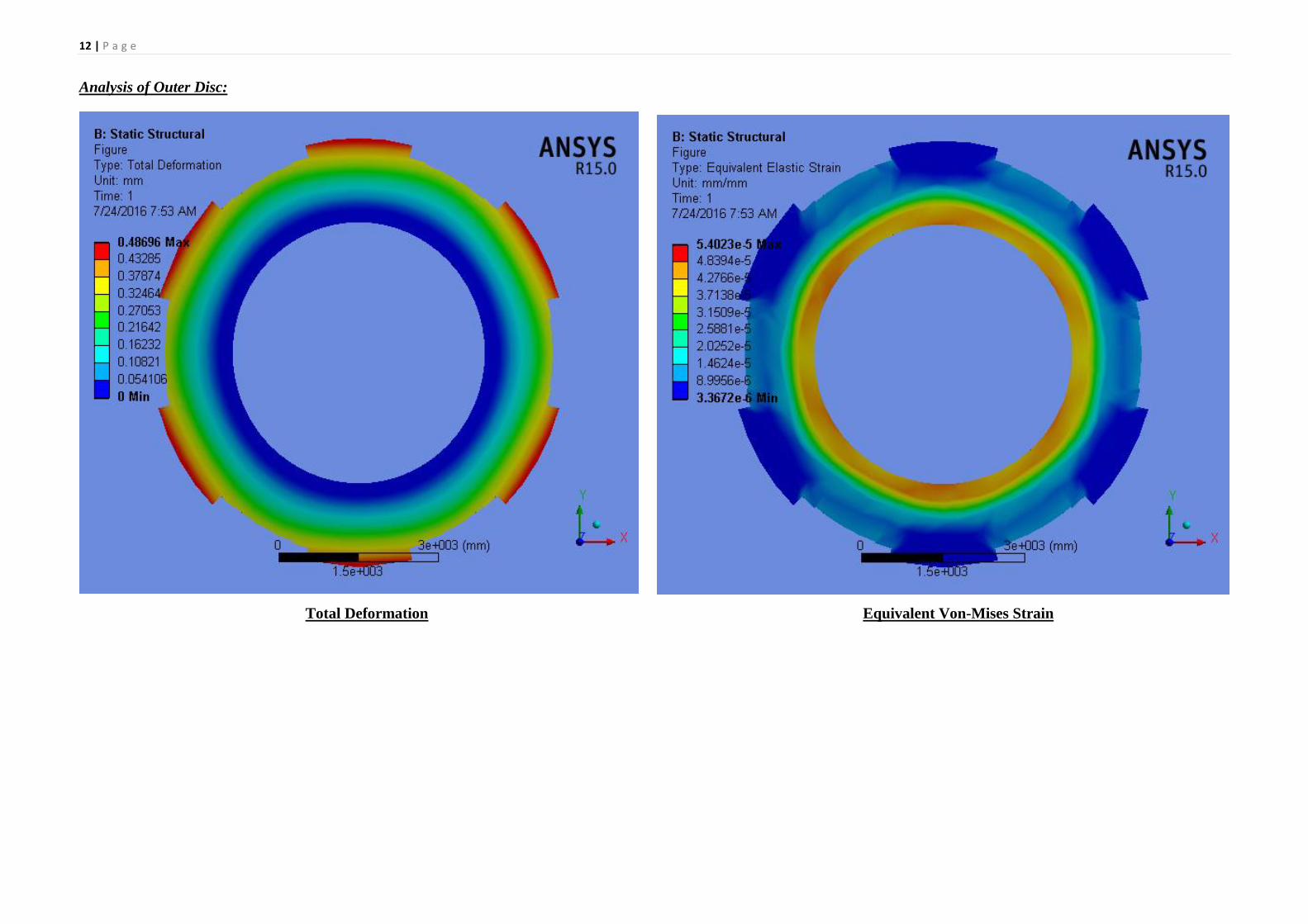
Analysis of Outer Disc:
Total Deformation Equivalent Von-Mises Strain

13 | P a g e
Equivalent Von-Mises Stress Factor of Safety

14 | P a g e
Strain Energy Induced
15 | P a g e
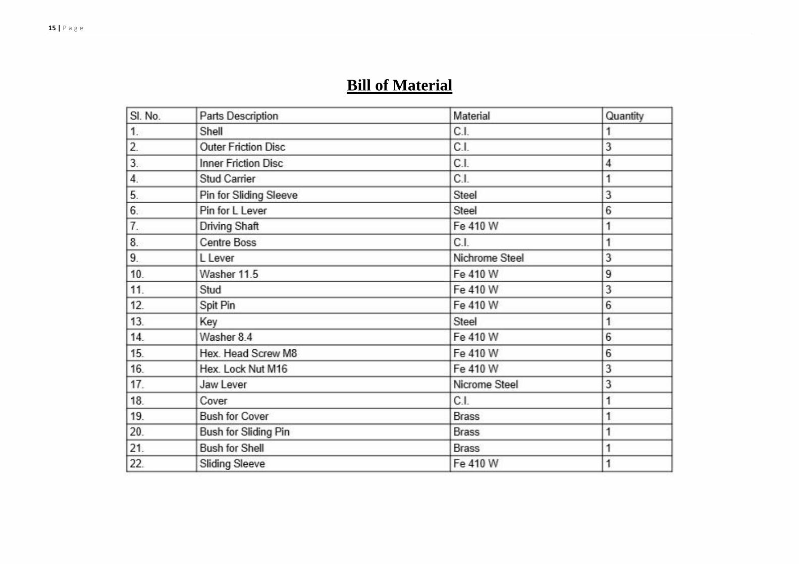
Bill of Material

16 | P a g e
Conclusion
In this work the Multi Plate Clutch parts and assembly is done using CREO Parametric 2.0 and the analysis is done using ANSYS 15.0 software. Here the boundary conditions are given in
ANSYS 15.0 are as follows:
Center circular potion is fixed.
One side 0.7 MPa pressure is given.
Other side 0.75 MPa pressure is given.
So from this analysis the resultant effects what will happen has tried to express. The analysis images will express what the Total Deformation, Equivalent Strain and Stress, Factor of Safety
and Strain Energy induced in the components. From the image of Factor of Safety of Clutch Plate and Pressure Plate are coming as 10.0-15.0. Hence the designed Clutch plate and Pressure
Plates are very much safe in operating condition.
Acknowledgements
Analysis of Multidisc Clutch Using FEA Ganesh Raut#1, Anil Manjare#2, P Bhaskar#3 #123Department of School of Mechanical and Building sciences, M. Tech Automotive
Division, VIT University, TamilNadu-632001, India. International Journal of Engineering Trends and Technology (IJETT) – Volume 6 Number 1- Dec 2013 ISSN: 2231-5381
http://www.ijettjournal.org (Page 5).
S. Jaya Kishor, M. Lava Kumar -Structural Analysis of Multi-Plate Clutch-(IJCTT) – volume 4 Issue 7–July 2013 ISSN: 2231-2803. Sankar.L, Srinivasan .R, Viswanathan .P and
Subramanian .R -Comparison study of al-fly ash composites in automobile clutch plates
International Journal of Emerging trends in Engineering and Development, Issue 3, Vol.3 (May 2013), ISSN 2249-6149.
Manfred Przybilla, Christian Kunze and Serdar Celik, Shachindr Dongaonkar―Combined Simulation Approach for Dry Clutch Systems” ISSN 0148-7191, SAE international.
Design of Machine Elements by V. B. Bhandari, 3rd Edition, ISBN : 978-0-07-068179-8 ( Page No. 456-459)


![DESIGN AND ANALYSIS OF CLUTCH LINER USING POLYMER FIBRE · “Static Structural Analysis of Multiplate Clutch with Different Friction Materials”, [3] Arvind vadiraj “Engagement](https://static.fdocuments.in/doc/165x107/5f0ff7cb7e708231d446c846/design-and-analysis-of-clutch-liner-using-polymer-fibre-aoestatic-structural-analysis.jpg)