DESIGN AND ANALYSIS OF IMPACT CRUSHERS -...
49
DESIGN AND ANALYSIS OF IMPACT CRUSHERS A THESIS SUBMITTED IN PARTIAL FULFILLMENT OF THE REQUIREMENTS FOR THE DEGREE OF Bachelor of Technology in Mechanical Engineering By SIDHARTHA PATNAIK Roll-10303035 BISWAJIT PATTNAIK Roll-10303065 Department of Mechanical Engineering National Institute of Technology Rourkela 2007
-
Upload
nguyennhan -
Category
Documents
-
view
215 -
download
0
Transcript of DESIGN AND ANALYSIS OF IMPACT CRUSHERS -...

DESIGN AND ANALYSIS OF IMPACT CRUSHERS
A THESIS SUBMITTED IN PARTIAL FULFILLMENT
OF THE REQUIREMENTS FOR THE DEGREE OF
Bachelor of Technology in
Mechanical Engineering
By
SIDHARTHA PATNAIK Roll-10303035
BISWAJIT PATTNAIK Roll-10303065
Department of Mechanical Engineering National Institute of Technology
Rourkela 2007

DESIGN AND ANALYSIS OF IMPACT CRUSHERS
A THESIS SUBMITTED IN PARTIAL FULFILLMENT
OF THE REQUIREMENTS FOR THE DEGREE OF
Bachelor of Technology in
Mechanical Engineering
By
SIDHARTHA PATNAIK Roll-10303035
BISWAJIT PATTNAIK Roll-10303065
Under the guidance of
Prof. N.Kavi
Department of Mechanical Engineering National Institute of Technology
Rourkela 2007

CERTIFICATE This is to certify that the project work entitled “Design and Analysis of Impact Crushers” by Sidhartha Patnaik and Biswajit Pattnaik has been carried out under my supervision in partial fulfillment of the requirements for the degree of Bachelor of Technology during session 2006-07 in the Department of Mechanical Engineering , National Institute of Technology, Rourkela and this work has not been submitted elsewhere for a degree. Place: Rourkela Prof. N.Kavi Date: 1/5/2007 Professor
Mechanical Engg. Dept. Rourkela-8

ACKNOWLEDGEMENT We take this opportunity to express our gratitude to all those who motivated,
encouraged and helped us in the project work.
We are grateful to our supervisor, Prof.N.Kavi, for his kind support, guidance and
encouragement throughout the project work, also for introducing to us this topic, which
has been very interesting and has given us great insight to the future work on this area.
We also wish to thank Dr.B.K.Nanda, Head of Department of Mechanical
Engineering, for his encouragement, patience and resourcefulness throughout the
development of this project.
We would like to take the chance to express our appreciation to our family
members.Their continuous love and support gave us the strength for pursuing our dream.
Special thanks to our friends and other members of the department for being so
supportive and helpful in every possible way.
NIT Rourkela
1st May,2007 Sidhartha Patnaik
Biswajit Pattnaik

ABSTRACT
Crushers are major size reduction equipment used in mechanical , metallurgical
and allied industries.They are available in various sizes and capacities ranging from 0.2
ton/hr to 50 ton/hr.They are classified based on different factors like product size and
mechanism used.Based on the mechanism used crushers are of three types namely Cone
crusher,Jaw crusher and Impact crusher. Our objective is to design various components of
an Impact crusher like drive mechanism, shaft, rotor ,hammers, casing ,feed and
discharge mechanism which will be useful in minimizing weight, cost and maximizing
the capacity. Impact crushers: they involve the use of impact rather than pressure to crush
materials. The material is contained within a cage, with openings on the bottom, end or
side of the desired size to allow pulverized material to escape. This type of crusher is
usually used with soft material such as coal, seeds or soft metallic ores. The mechanism
applied here is of Impact loading which is applicable when the time of application of
force is less than the natural frequency of vibration of the body.
As because here the hammers are rotating at a very high speed, time for which the
particles come in contact with the hammers is very small, so here impact loading is
applied.

CONTENTS Chapter No. Description Page No. Chapter 1: Introduction
1.1 Introduction 1
1.2 Design Parameters 1
1.3 Types of crushers 3
1.3.1 Horizontal Shaft Impact Crusher 3
1.3.2 Vertical Shaft Impact Crusher 4
1.4 Advantages of Impact crushers 5
1.5 Principle of Operation 5
Chapter 2: Design and Calculation
2.1 Design of V-Belt drive 7
2.2 Design of Shaft 10
2.3 Design of Hammers 14
2.3.1 Using Impact Bending 14
2.3.2 Using Strain Energy method 21
2.4 Design of conveyor belt 22
Chapter 3: A performance model for impact crusher 3.1 Mass balance 23
3.2 Impact energy 24
3.3 Classification function 25
3.4 Breakage function 26
Chapter 4: Hammer locking arrangement

4.1 General overview 27
4.2 Description 28
Chapter 5: Study of Feeder Mechanisms
Chapter 6: Computerisation 5.1 Computerisation of V belt design 32
5.2 Computerisation of Hammer design 33
Chapter 7: Conclusion 35 References 36

LIST OF FIGURES
Figure no. Title Page no. Figure 1.1 Sectional view of horizontal impact crusher 2 Figure 1.2 Front view of horizontal impact crusher 2 Figure 1.3 vertical shaft shaft impact crusher top view 4 Figure 1.4 Vertical shaft impact crusher front view 4 Figure 2.1 Orthographic view of horizontal impact crusher 7 Figure 2.2 Diagram showing diff. mechanisms in a horizontal crusher 7 Figure 2.3 V belt drive 9 Figure 2.4 V belt drive line diagram 11 Figure 2.5 V belt drive line diagram 13 Figure 2.6 Cross section of hammer 16 Figure 2.7 Forces diagram 17 Figure 2.8 Bending moment diagram 17 Figure 2.9 Force diagram on hammer 19 Figure 2.10 Conveyor belt line diagram 23 Figure 3.1 Classification and breakage function line diagram 27 Figure 4.1 Hammer locking arrangement diagram 31

CHAPTER:1
INTRODUCTION

Introduction
A crusher is a machine designed to reduce large solid chunks of raw material into
smaller chunks.
Crushers are commonly classified by the degree to which they fragment not
starting material with wares crushers not reducing it by much, intermediate cruiser
fragmenting it much more significantly and grinders reducing it to a fine power.
Impact crushers: they involve the use of impact rather than pressure to crush
materials. The material is contained within a cage, with openings on the bottom, end or
side of the desired size to allow pulverized material to escape. This type of crusher is
usually used with soft material such as coal, seeds or soft metallic ores:
Hammer mills- Utilize heavy metal bars attached to the edges of horizontal
rotating disks by hinges, which repeatedly strike the material to be crushed.
Ball mills- Use metal balls in rotating cylinders.
Stamp mills- Use cans to lift weighted vertical hammer which are dropped by
gravity to crush the material.
DESIGN PARAMETERS:
The principal design parameters that drive crushing plant selection and configuration
included.
1. Production Requirements
2. Ore characteristics
3. Project location
4. Operational considerations
5. Climate conditions
6. Capital cast
7. Safety & environment
8. Life of mine plants.
9. Maintenance requirements.

Fig.1
Fig.2

ADVANTAGES:
1. Hammers have four crushing positions to maintain a more const. gradation and
greater top size control.
2. Less capital outlay.
3. High degree of product size control
4. Long life of wear components.
For different m/c wts the horse power required are as follows:
Wt (kg) Horse power
15000 150
20000 200
25000 250
35000 300
45000 350
70000 400
The hammer is subjected to:
1. Shear force at point of fixation (attachment).
( ) .2
all catet of area
wnF τγ<=
γ = distance from axis of shaft.
2. Centrifugal force on hammers mrww2
Compressive force
area facewmF
2γ=
3. Bending due to raw material strike
a) Depends on the non flow rate
Shaft is subjected to:
1. Torsion

Max. Torsion will be experiences at L/2.
L= length of shaft.
2. Bending
Assume it to be a cantilever of length L/2.
Principle of operation:
Feed material drops through the feed tube onto chi shoe table or enclosed rotor which,
through centrifugal force throws the material against stationary anvils when the rock
impacts the anvils at 900 angle, it shelters along natural grain structures creating a
uniform cubical product. This is simple and economical to operate. Product output is
easily controlled by varying the rotor speed. each crusher can accommodate several
different rotor, shoe table anvil ring and auto generous rock shelf combinations.
Horse Power --------- Model ---------- Capacity (Tonnes)
75-125 5-50
150-250 30-125
200-300 50-175
200-400 100-275
300-600 200-400
250-500 150-400
300-800 250-500
800-1000 600-1300

VERTICAL SHAFT IMPACT CRUSHER
fig 1.3
fig 1.4

CHAPTER 2
DESIGN AND CALCULATION
DESIGN OF HORIZONTAL SHAFT IMPACT CRUSHER

HORIZONTAL SHAFT IMPACT CRUSHER
Fig2.1 Fig2.2

1. Design of V-belt Drive
Fig.3
MATERIAL SELECTION: LEATHER
Mechanical properties:
µ = 0.15
σ all=7 MPα=7N/mm2
ρ= 1.2 x 10³ Kg/m3
Design calculations:
P = 15 HP
= 15 x 746 W ≈12 Kw
2β = 300 (assumed)
N = 1440 rpm
α = 150 mm
W =17 mm

T = 11 mm
Fig.4
Speed ratio = 1.6
D = 220 mm
Tan 150 = 8.5 /b
B= 31.7 mm]
Tan 150 = P/20.7
2P = 11.1 mm
a = ½ (28.1) (11)= 154.5 mm2 ≈ 160 mm2
V = π x 0.15 x 1440 /60 = 11.3 m/s
Mass of belt /m = 0.19 kg / m
Tc = mv2 = o.19 x 11.3 2 =24.26 N
Cmin = 0.55 (D+d) + T
= 0.55 (150 +220) + 11
=214. 5 mm
C = 230 mm
θ =2 cos-1 D-d /2c = 144.560
22
1 461.1 TT eTT
1 =⇒= μθ
12 = (T1 – T2) x 11.3 x 2

aummN
mm 160 x
NT
NT T
knTT
2
2
σσ
σ
2
1
2
21
/67.10
1707
1683
1152531461.0
531.0
=⇒
=
=
=⇒=
=−⇒
Design fails
( ) 2260371421 mmxxa ==
0
0
155.1421405.41
15tan
05.41
15tan11
mmmmp
Pmmb
b
≈=⇒−
=
=⇒
=
Fig.5
Cmin = 0.55 (370 +14
= 218 mm ≈230 mm
T = σ x a →σ = 1707/260 = 6.56 N/mm2 , < σ au
Hence design is safe.

2- Shaft Design
Material of hammer: CI
Density of CI = 8000 kg /m3
Cross Section of hammer
Fig.6
Fig.7
N = 20” x (2.54)3 cm3
= 312. 5 cm 3
Wt = 6 x 8000 x 312.5
= 15.73 kg
W = 1.96 kg /m
R1 + R2 = 15.73 x 9.8 = 154.154 N
R2 x 91 = 154.73 x 31.5
R2 = 53.36 N, R1 = 100.6 N
M = R1x –w (x-16) (x-16/2)
= 0.98 x2 +131.96x-250.88
For maximum bending moment
dm /dx =0
=>100.6 -0.98 (2x-32)=0
=> x= 67
Maximum = 100.6 x 67 – 0.98 (672- 256- 32 x 67)
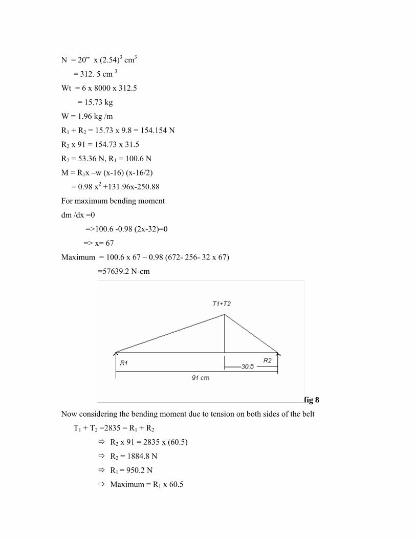
=57639.2 N-cm
fig 8
Now considering the bending moment due to tension on both sides of the belt
T1 + T2 =2835 = R1 + R2
R2 x 91 = 2835 x (60.5)
R2 = 1884.8 N
R1 = 950.2 N
Maximum = R1 x 60.5
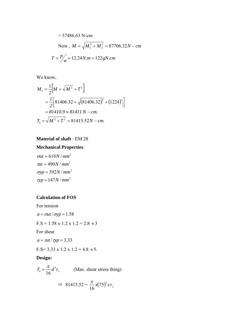
= 57486.63 N-cm
Now , cmNMMM −=+= 32.8770622
21
cmgNmNwpT .122.24.12 ===
We know,
[ ]( ) ( )
.52.81415
122432.8140632.81406
21
22
22
22
cmNTMT
cm.N 81411 81410.9 21
TMMM
e
e
−=+=
−≈=⎥⎦⎤
⎢⎣⎡ ++=
++=
Material of shaft : EM 28
Mechanical Properties:
2
2
2
2
/147/392
/490/618
mmNypmmNyp
mmNutmmNut
=
=
=
=
τ
σ
τ
σ
Calculation of FOS
For tension
58.1/ == yputa σσ
F.S = 1.58 x 1.2 x 1.2 = 2.8 3 ≈
For shear
33.3/ == yputa ττ
F.S= 3.33 x 1.2 x 1.2 = 4.8 5. ≈
Design:
se dT τπ 3
16= (Max. shear stress thing)
81415.52 = ( ) sxx τπ 37516

2/3627.983 cmNs =τ
( ) ( )
2
2
/
/985
490.
cmN10 x 98
mmNSF4
utsalls
=
=== ττ
( )allss ττ < hence design is safe.
According to max principal stress theory
( )33 5.7814113232
xx
dMe
ππσ ==
σσ < all hence design is safe
3. Hammer design:
Impact loading
A load that is suddenly applied to a m/c or structure is called an impact load. The effect
of impact loads differs appreciably from that of static loads because, with a suddenly
applied load, both the magnitude of the stresses produced and resistance properties of the
material are affected. The most common type of impact testing is the “notched bar
testing” or the izode impact test.
Impact bending stress:
Cantilever bean subjected to concentrated load.
Assuming the open screen area / hammer
= 50 % of total area / hammer
22 52.6454.210050210 cmcmxxx ==

fig 9
Total tonnage = 2000 kg /hr
= 0.55 kg / sec
Tonnage / hammer = 0.55 /24
= 0.023 kg /sec.
Assuming it to be a concentrated coal falling from a distance 1 ft.
Applying impact equation
W(h+y) = py/2
Where P is the equivalent static load
0.023 (30.5 +y) = py/2
Now for a simply supported bean subjected to a centre load the deflection is
YL
48EIP EI
PLY 3=⇒=48
3
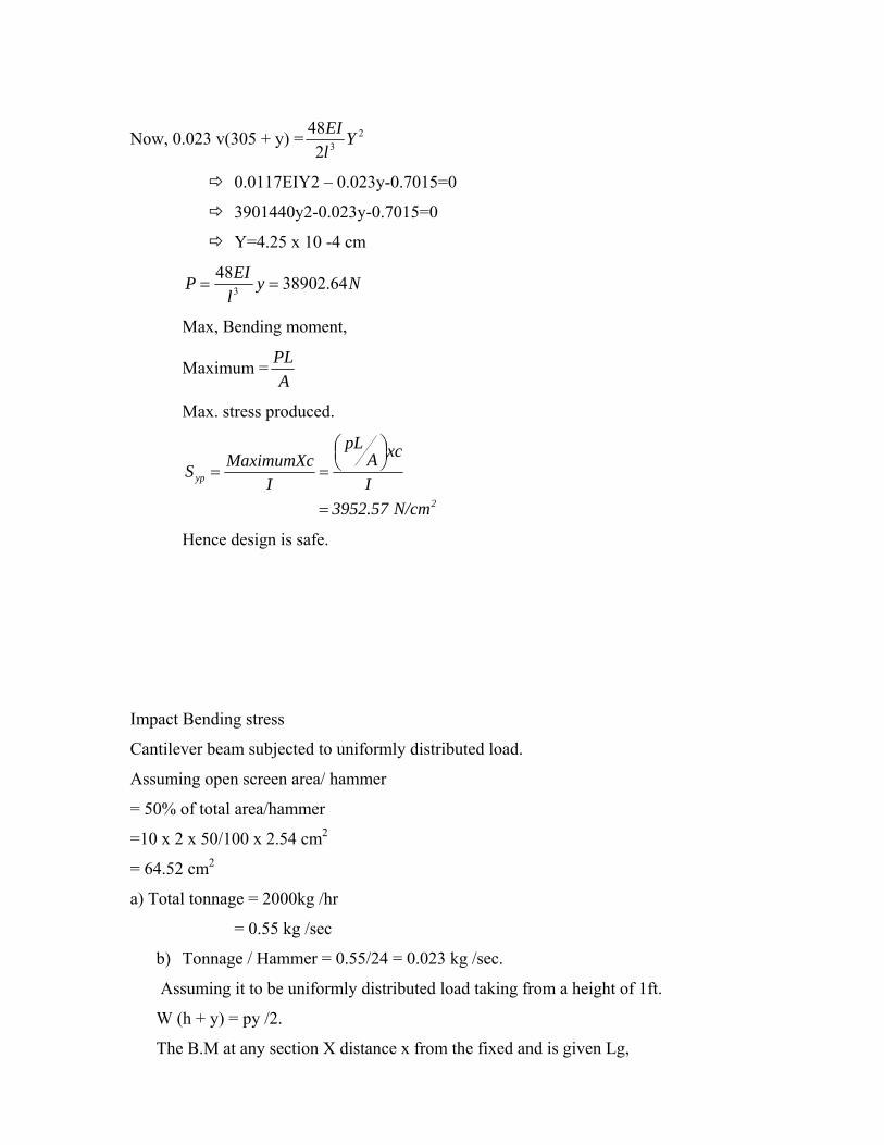
Now, 0.023 v(305 + y) = 232
48 YlEI
0.0117EIY2 – 0.023y-0.7015=0
3901440y2-0.023y-0.7015=0
Y=4.25 x 10 -4 cm
NylEIP 64.38902483 ==
Max, Bending moment,
Maximum =A
PL
Max. stress produced.
2
yp
N/cm 3952.57 I
xcApL
IMaximumXcS
=
⎟⎠⎞⎜
⎝⎛
==
Hence design is safe.
Impact Bending stress
Cantilever beam subjected to uniformly distributed load.
Assuming open screen area/ hammer
= 50% of total area/hammer
=10 x 2 x 50/100 x 2.54 cm2
= 64.52 cm2
a) Total tonnage = 2000kg /hr
= 0.55 kg /sec
b) Tonnage / Hammer = 0.55/24 = 0.023 kg /sec.
Assuming it to be uniformly distributed load taking from a height of 1ft.
W (h + y) = py /2.
The B.M at any section X distance x from the fixed and is given Lg,

( )22
2
2xlw
dxydEI −−==
Integrating ( ) 13
6Cxlw
dxdyEI +−=
( ) 2
34
624w- EIy ,, cwlxlo
dxdyox +−−===
0 y 0, x ==At
244
2wlc =
( )24624
434 wlxwlxlwcEIy +−−−=
work done due to impact distributed load,
= ( )⎥⎦
⎤⎢⎣
⎡−−
−−
EIwlx
EIwl
EInlwhdx
lw
24624
434
Net work done = ∫ aw
== ( )∫ ⎥
⎦
⎤⎢⎣
⎡+−
−−
i
o EIwlx
EIwl
EIxiwhdx
lw
24624
434
= ( )⎥⎦
⎤⎢⎣
⎡+−
−− ∫
l lEI
wzl
EIwlxl
EIwfehi
lw
0
5235
5246524
= ⎥⎦
⎤⎢⎣
⎡+−⎟⎟
⎠
⎞⎜⎜⎝
⎛ −+
EIwl
EIwll
EIwhl
lw
12012524
555
= ⎥⎦
⎤⎢⎣
⎡−
EIwlHL
Lw
12
5
= ⎥⎦
⎤⎢⎣
⎡−
EIwlhlW
12
5
h = 1ft = 12 inch = 30.5 cm
w = 0.023 kg/s. l = 12.7 cm
EI = .33298.51 mm2
W = 0.023 ⎥⎦
⎤⎢⎣
⎡×××
−51.3329812100
)7.12(023.0100
5.304
4

= 0.007014996 J/s
static load work done
= ( )∫ ⎟⎟
⎠
⎞⎜⎜⎝
⎛+−
−−
c
dxwlxwlxlwlEIp
2424242
434
= ( )⎥⎥⎦
⎤
⎢⎢⎣
⎡+−
⎭⎬⎫
⎩⎨⎧ −−− lwllwlxlw
lEIp
l
242.
6524)1(
2
423
0
5
= ⎥⎦
⎤⎢⎣
⎡+−
−24121202
555 wlwlwllEIp
= lEI
pwlwlwllEIp
40 wl
120510
2
5555
−=⎥⎦
⎤⎢⎣
⎡ +−−
0.007014996 = ⎥⎦
⎤⎢⎣
⎡⎟⎟⎠
⎞⎜⎜⎝
⎛××
× 1007.023.0
51.332981
1007.1240
5PP
P = 33298.51 X 0.4 X 12.7 X 0.007 X 023.07.12
100 5
×⎟⎠⎞
⎜⎝⎛
= 023.07.12
10001.11845
×⎟⎠⎞
⎜⎝⎛×
Mmax = 51024.82 ×=lP
Mmax = 200
7.121024.8 5 ××
= MN.10523.0 5×
8
5
1075.2710054.210523.0 −××
××=bσ
= 28 /109.47 mn×
= 47.9 x 10⁴ n/cm2
= 0.47 NPa
considering the load to be acting on 1 hammer
net workdone = ⎥⎦
⎤⎢⎣
⎡−
EIwlhw
12
4

= ⎥⎥⎦
⎤
⎢⎢⎣
⎡
××⎟
⎠⎞
⎜⎝⎛×−
51.33298121
1007.1255.0
1005.3055.0
4
= 0.1677499 J/s
0.1677499 = ( )
( ) 51.332981007.1240
1007.1255.0
5
××
××p
P = ( )( ) 407.12
100401677499.051.332985
5
××××
= 0.0183 x 1010 = 1.83 x 10⁸
Mmax = 200
7.121083.1 8 ××
= 0.110 X 10⁸ n-m
88
1075.2710054.210 0.116 b −××
××=σ
= 10636.42 x 108 N/m2
= 106.36 mPa
Cantilever Beam Subjected to End concentrated Impact load.
w(h+y) = py/2
3
3 33 l
EIYpEI
Ply =⇒=
zy
lEIhtyw
2
3 .3)( =
( ) zy
W
y2
3
17.12
51.332983100
5.3055.0 ×=⎟
⎠⎞
⎜⎝⎛ +⇒
( ) 2710438399.2305.055.0 yty ×=⇒ 2710438399.255.016775.0 yy ×=+⇒
016775.055.010438399.2 27 =−−×⇒ yy
( )7
72
10438399.2216775.010438399.2455.0
55.0××
×××+±=y
= 829.54 x 10⁻⁷ m
= 829.54 x 10⁻⁴ mm

= 0.08 mm or approximately equal to 0.1 mm
ylEIp 3
3=
= ( )
73 1054.829
127.051.332983 −××
×
= 4045.5 N
Mmax = Pl = 4045.5 x 0.127
= 573.78 N.m
drawing 78.573 σ=×⇒Ii
c = 1” = 2.54 cm
81075.271002.54573.78 b −××
×=⇒σ
= 0.47 x 10⁸ N/m2
= 0.47 X 10⁷ N/cm2
= 4700 N/cm2
DESIGN OF HAMMERS CONSIDERING:
1. END LOADING WITH FATIGUE
Fatigue loading is not applicable in this case
2. By using Strain Energy method and approximating the loading to be a static one.
Shear stress at any distance y.
yAIbFq = F = Shear force
= ( )( ) ⎟⎠⎞⎜
⎝⎛ +− 242
ydydbIbF
I = 12
3bd
⎟⎟⎠
⎞⎜⎜⎝
⎛−=⇒ 2
2
3 46 ydbd
Fq

)(2
2
volumeG
qdv =
( )(dxbdyydbd
FG
.4
621
2
22
3 ⎥⎦
⎤⎢⎣
⎡⎟⎟⎠
⎞⎜⎜⎝
⎛−= )
Total shear strain energy
= ∫∫2
d
o
L
o
dv
dydx bydbd
FG
Ld
.4
621
22
22
0 03
12
⎟⎟⎠
⎞⎜⎜⎝
⎛−⎟
⎠⎞
⎜⎝⎛= ∫ ∫
bdGLF 2
53
=
Workdone = w = ½ pys
Equating, bdG
LF y2
s 56
=
bdG
LP U2
53
=
bdGPL Ys 5
6=
2/80
sec/4.555.0
mmNG
Nseckg P
=
==
mm
xxxmmxxYs
06.0
80)100)(54.2254.2()127(4.5
56
=
=
Material can be introduced by means of variable speed vein feeder. This type of feeder
can have its motor slowed by a programmable controller to the main drive motor of the
hammer mill.

CONVEYOR CALCULATION:
fig 10
Material: Rubber(1140 kg/m3)
Angle: 15o
Feed Rate: 2 metric ton/hr
We know,
Discharge(Q) = velocity(v) * Area(A)
= v*5/6*Π*r*(1 m)
r*v = 1/15* Π
Radius (r) Velocity(v)
10 cm 2.1 cm/s
11 cm 1.9 cm/s
13 cm 1.6 cm/s
15 cm 1.4 cm/s

CHAPTER 3
A PERFORMANCE MODEL FOR IMPACT CRUSHER

ANALYSIS
A performance model for impact crushes (study)
The goal of the study is to predict the product size distribution, provided that the crushers
rotor velocity and radius as well as the feed rate and size distribution are known before
hand.
Classification and breakage Fn’s
Fig 1
General scheme of breakage process
Impact breakage takes place on a very short time scale and implies a dynamic crack
propagation that leads to a much faster failure of particles.
The impact generates compressive and tensile shock waves traveling throughout the
particle. The presence of a significant, rapidly growing tensile stress helps the
particles to break from within.

Mass Balance
F feed
P product
C Classification operator, computes the probability of breakage of each
particle size.
B breakage operator
Governs the redistribution of broken particles in the preliminary defined size classes.
P = (I-c), (I-B.C) -1, f
Where, I identity matrix
IMPACT ENERGY PER UNIT MASS:
HORIZONTAL SHAFT:
Assumptions:
1. Rotor mass much greater than mass of single particles in the feed
2. Before impact, linear velocity of the crushing bar is much more important than the
particle velocity. Hence KE of particles is negligible.
Considering the COLM,
E = 0.5 (R + 0.5Hb)2. W2
Where, R Rotor radius
Hb height of impact surface of crushing bar.
W rotor angular velocity
Vertical shaft
Assumption
1. particle energy does not change during its flight from the rotor periphery to the
crushing walls.
E = Rv2. W2
Rv rotor radius
W(S) angular velocity
Classification function:
For cone and jaw crushers
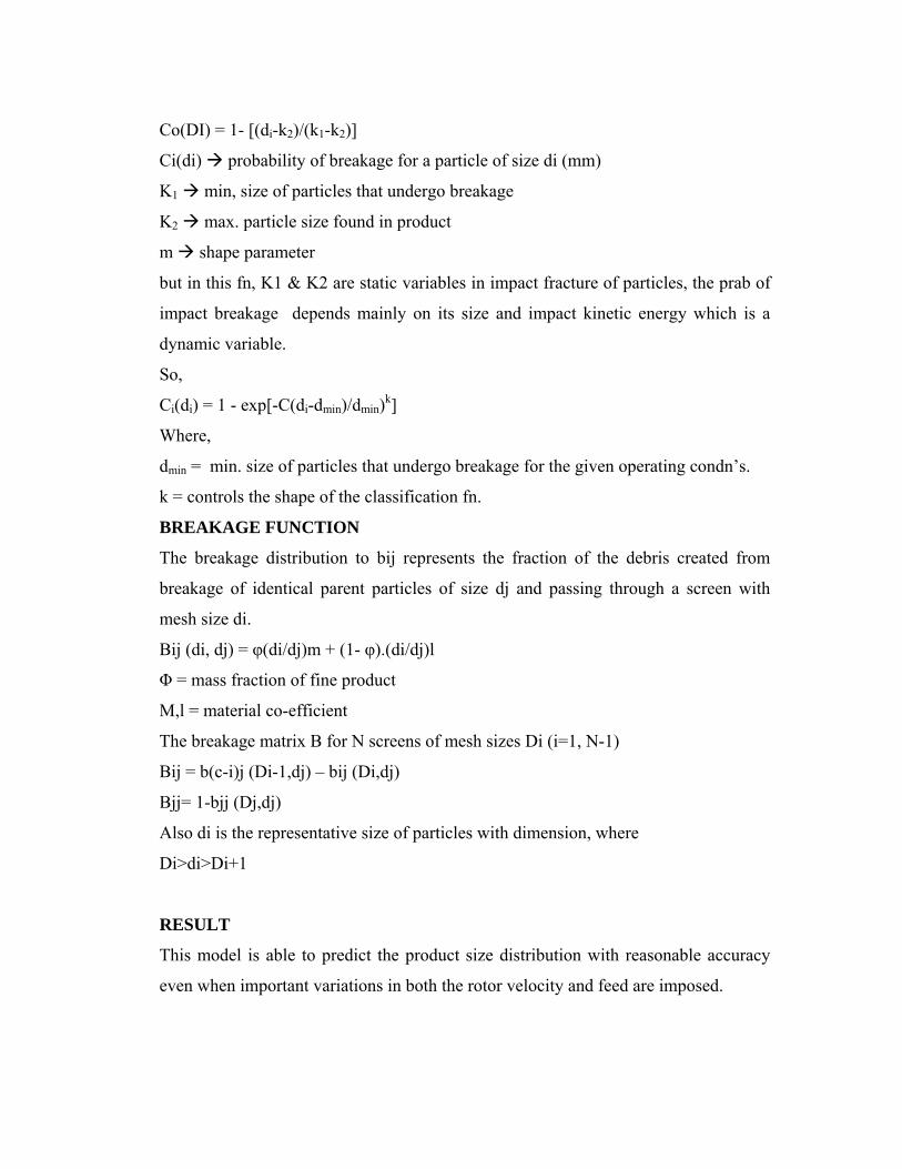
Co(DI) = 1- [(di-k2)/(k1-k2)]
Ci(di) probability of breakage for a particle of size di (mm)
K1 min, size of particles that undergo breakage
K2 max. particle size found in product
m shape parameter
but in this fn, K1 & K2 are static variables in impact fracture of particles, the prab of
impact breakage depends mainly on its size and impact kinetic energy which is a
dynamic variable.
So,
Ci(di) = 1 - exp[-C(di-dmin)/dmin)k]
Where,
dmin = min. size of particles that undergo breakage for the given operating condn’s.
k = controls the shape of the classification fn.
BREAKAGE FUNCTION
The breakage distribution to bij represents the fraction of the debris created from
breakage of identical parent particles of size dj and passing through a screen with
mesh size di.
Bij (di, dj) = φ(di/dj)m + (1- φ).(di/dj)l
Φ = mass fraction of fine product
M,l = material co-efficient
The breakage matrix B for N screens of mesh sizes Di (i=1, N-1)
Bij = b(c-i)j (Di-1,dj) – bij (Di,dj)
Bjj= 1-bjj (Dj,dj)
Also di is the representative size of particles with dimension, where
Di>di>Di+1
RESULT
This model is able to predict the product size distribution with reasonable accuracy
even when important variations in both the rotor velocity and feed are imposed.

CHAPTER 4
HAMMER LOCKING MODEL FOR IMPACT CRUSHER
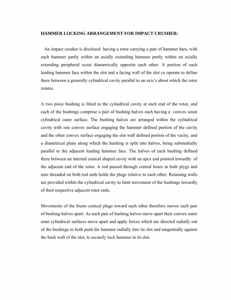
HAMMER LOCKING ARRANGEMENT FOR IMPACT CRUSHER:
An impact crusher is disclosed having a rotor carrying a pair of hammer bars, with
each hammer partly within an axially extending hammer partly within an axially
extending peripheral scoot diametrically opposite each other. A portion of each
leading hammer face within the slot and a facing wall of the slot co operate to define
there between a generally cylindrical cavity parallel to an axis’s about which the rotor
rotates.
A two piece bushing is fitted in the cylindrical cavity at each end of the rotor, and
each of the bushings comprise a pair of bushing halves each having a convex seoni
cylindrical outer surface. The bushing halves are arranged within the cylindrical
cavity with one convex surface engaging the hammer defined portion of the cavity
and the other convex surface engaging the slot wall defined portion of the vacity, and
a diametrical plans along which the hushing is split into halves, being substantially
parallel to the adjacent leading hammer face. The halves of each bushing defined
there between an internal conical shaped cavity with an apex end pointed inwardly of
the adjacent end of the rotor. A rod passed through central bores in both plygs and
nuts threaded on both rod ends holds the plugs relative to each other. Retaining walls
are provided within the cylindrical cavity to limit movement of the bushings inwardly
of their respective adjacent rotor ends.
Movements of the frusto conical plugs toward each other therefore moves each pair
of bushing halves apart. As each pair of bushing halves move apart their convex outer
semi cylindrical surfaces move apart and apply forces which are directed radially out
of the bushings to both push the hammer radially into its slot and tangentially against
the back wall of the slot, to securely lock hammer in its slot.

DESCRIPTION OF THE DRAWINGS
Fig 1.
Fig. 1 of the drawings is a view in elevation and partly in section, showing an impact
crusher according to the present invention.
Fig. 2 is an exploded isometric view of a rotor for the crusher shown in Fig.1.
Referring to fig. 1 an impact crusher is shown which comprises a housing.
1. having disposed within a lower area of a rotor.
2. mounted on a shaft
3. which is carried by suitable journal bearing.
4. the housing 1 defines a material feed
Opening 5 over a feed chute 6 inclined downwardly towards the rotor 2. The feed chute 6
delivers rock to hammers 7 & 8 which are carried by 2 in a manner chute 6 directs feed
rock to rotor 2 at a location where its hammers 7 & 8 are ascending with the result that
the impact of hammers 7 & 8 on rock breaks the rock into smaller particles w3hich are
thrown upwardly to break into even smaller particles upon impact with a complement of

primary target breaker bars 12 and 13 which are carried by the sassing 1. a secondary
crushing occurs when such particles drop downwardly from bars 12 and 13 to be again
struck by hammers 7 and 8 and thrown towards a discharge are 14 where the particles
impact with a vertical array of secondary target bars 15 d\close to the periphery of the
rotor 2 one or more adjustable and yieldable breaker bars 16, 16’ may be arranged.
Adjustable and yieldable moan such as for bars 16 and 16’ are well known. Any particles
not between the bars 15 and into discharge area 14 progress downwardly towards the bar
16’ where such particles are subjected to a final crushing as the particles are nipped and
urged through the space between the rotor 2’ and bar 16’ to the lowest portion of the
discharge area. The casing 1 may include a pivoted position 18 connected tro base
structure 19 by a hinge so operative to open the casing and provided access to the internal
mechanisms.
The rotor 2, shown in elevation in Fig-1 and the exploded isometric in Fig-2 will now be
described. The rotor may be thought of as comprising an elongated central body portion
23 with a pari of axially extending slots 24, 25 and a pair of diametrically apposed spiral
body extensions 26, 27. with reference to Fig.2 slot 24 is shown as having a leading wall
28, a floor 29 and a back wall 30. The body extensions 126, 27 each project progressively
farther radially outward beginning at leading wall 28 of one slot and reaching maximum
radial projection at a terminus defining a face 31 planner with back wall 30 of the other
slot.
First and second hammer means, whose in both Fig-1 and Fig-2 as the hammer bars 7 &
8, are each arranged in one of the slots 24, 25 and project outwardly of such slots with a
leading hammer face 34 extending outwardly and terminating with an edge 35 outward of
slot edge 25 as far as the readially outer edge of the face 31.
Referring now again to Fig-2, an radial inner surface portion 38 of the leading hammer
face 34 of bar 7, is shaped to define a concave semi cylindrical cavity. The leading slot
wall 28 is also shaped to define a concave section in the cylindrical cavity 28, 38 at each
end there of. The two bushing pieces 39, 40 are each halves of a complete bushing and
each have a convex semi cylindrical outer surface 41, 42 respectively, which together
define a frusto conical cavity. A frustoconical plug 45 is provided for each bushing 39, 40
and each plyg 45 conforms to the shape of the frusto conical cavity defined by bushing

surfaces 43, 44. each plug 45 has a central bore 46 through which a rod 47 may be
inserted. The rod 47 is threaded on both ends for engagement with threaded nuts 48,49.
In the assembly of rotor 2, hammer 7 for example is placed is slot 24 on floor 29 and
abutting against back wall 30, with wall 38 and surface 38, thereby co-operating to define
there between a generally cylindrical cavity. One of the two piece bushings 39, 40 is
inserted from and of the rotor 2 with apex ends of the inner frusto conical cavities 43, 44
pointed inwardly of the adjacent rotor ends. The bushings 39, 40 are moved inwardly
untill the pieces abut against semi annular retaining walls 52, 53 in the cavity defined by
surface 38. The retaining walls 50-53 limit movement of the bushings inwardly their
adjacent rotor ends. With the two piece bushings 39, 40 each abutting against a pair of
retaining walls 50, 52 and 51, 53 respectively, the bushing surface 41 is aligned to
engage slot wall surface 41 is aligned to engaged slot wall surface 28, preferably with a
diametrical plane x – x’ along which the bushing is split into halves 39, 40 being
substantially parallel to the adjacent slot back wall 30 referri9ng again to Fig.2, the frusto
conical plugs as are aligned with their apex ends pointed inwardly and each is inserted
into one of the bushing cavities defined by surface 43, 44. the rod 47 is then inserted
through the bares of plugs 45 and the nuts 48, 49 are secured to its ends.
In the operation of the described assembly to source a hammer, such as hammer of as the
plugs 45 are driven in their respective bushings 39, 40 the plugs 45 are moved inwardly
toward each other, the bushing halves 39, 40 surrounding each plug 45 move apart.
Finally, as hushing halves 39, 40 move apart, their convex semi cylindrical outer surface
41, 42 move apart and apply forces which are directed radially of the bushing halves 39,
40 to both push hammer 7 tangentially w.r.t the central body portion 23 of rotor 2, against
the back wall 30 of slot 24, to securely lock the hammer 7 in its slot 24.

CHAPTER 5
STUDY OF FEEDER MECHANISMS

Feeder Mechanisms
Various conveyer systems
1. Telescopic belt conveyor
They are designed to achieve high handling rates. Their dimensions can be altered
to befit distinct machine requirements.
Advantages
Reducing loading and unloading time
Improved handling efficiency
Improved operative safety
2. Screw conveyor
The can be mounted in horizontal vertical and inclined configurations. These
primarily consist of a conveyor screw, rotating in a stationary trough Appl’s.
Can be used as feeders in crushers
Can be used as a vertical lifter for powder and granule.
3. Vibrating Screen
They consist of robust vibrating s feens used widely for grading and sieving.
Composing a main screen, screen web electric motor, eccentric block, rubber
spring and coupler these vibrating screens can be customized to suit the customers
requirement.
Features
highly reliable and durable
Eccentric type systems
high screening capacity
No transmission of screen panels
Rigid and vibrating
Appln’s
Used in industries like crushing plants
CASING
The mill case is welded steel construction and built in three sections. The lower
half is in one piece and upper half is in two sections. The feed intake section of
the upper half is bolted to the lower half resulting in a permanent dust type
connection between the feeding and mill intake.
The remaining top section is hinged for access to interior of the mills for changing
hammers, hammer pins and screens. All mating surfaces are mechanized for an
accurate, dust tight fit. Single latch door for easy maintenance and cleaning.
Gasketed door for dust tight operation.
Screen
The degree of fineness of the ground product depends upon the size of the screen
perforations. The screens are in two sections. In addition to the lower half circles
screen. Mills have an extra quarter screen located in the hinged section of the top
case. This increases the screen area by approximately 50% more than the
conventional designs.
Quick screen Release
The lower screen is held securely in place by a quick screen release mechanism,
ensuring a fight screen fit to guard against leakage of fine dust, which it allows
quick and easy changing of screens.

CHAPTER 6
COMPUTERISATION

Hammer Design Program: #include<stdio.h>
#include<conio.h>
#include<math.h>
void main()
float A,A’,T,D,p,m’,s,i,c,str;
const float F=12.3;
printf(“ENTER THE VALUE OF OPEN SCREEN AREA”);
scanf(“%f”,&A);
printf(”ENTER THE VALUE OF TOTAL TONNAGE PER HAMMER”);
scanf(%f”,&T);
printf(“ENTER THE VALUE OF EI”);
scanf(“%f”,&d);
printf(“ENTER THE VALUE OF I AND C”);
scanf(“%f%f”&i,&c);
printf(“ENTER THE VALUE OF STRESS ALLOWABLE”);
scanf(“%f”,&str);
printf(“THE MATERIAL SELECTED FOR HAMMER IS MS STEEL”);
a=48*E*I/2*l*l*l;
b=T*30.5;
c=T;
m=b*b-4*a*c;
x=-b+sqrt(m);
p=48*d*x/l*l*l;
m’=p*l/4;
s=m’*c/I;
if(s<str)
printf(“safe design”);
else
printf(“unsafe”);
}
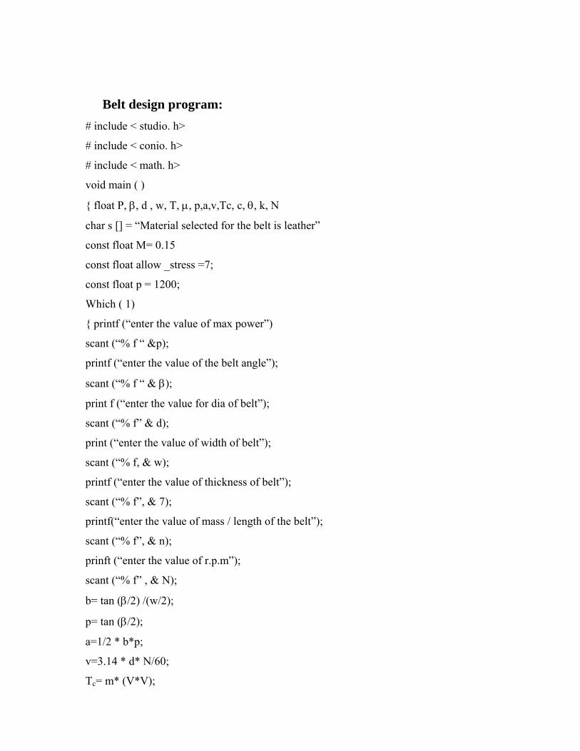
Belt design program:
# include < studio. h>
# include < conio. h>
# include < math. h>
void main ( )
{ float P, β, d , w, T, μ, p,a,v,Tc, c, θ, k, N
char s [] = “Material selected for the belt is leather”
const float M= 0.15
const float allow _stress =7;
const float p = 1200;
Which ( 1)
{ printf (“enter the value of max power”)
scant (“% f “ &p);
printf (“enter the value of the belt angle”);
scant (“% f “ & β);
print f (“enter the value for dia of belt”);
scant (“% f” & d);
print (“enter the value of width of belt”);
scant (“% f, & w);
printf (“enter the value of thickness of belt”);
scant (“% f”, & 7);
printf(“enter the value of mass / length of the belt”);
scant (“% f”, & n);
prinft (“enter the value of r.p.m”);
scant (“% f” , & N);
b= tan (β/2) /(w/2);
p= tan (β/2);
a=1/2 * b*p;
v=3.14 * d* N/60;
Tc= m* (V*V);

C=0.55 * (D+d) +T;
Printf (“enter the new approx value of C from the table”);
Scant (“% f “ , & C);
θ=2* cos-1 (D-d)/2*c;
K= μ*θ;
T1 = T1;
T2 =T2;
T=T1-Tc;
σ = T/a;
If (σ <σall).
{ printf (“design is safe”);
break;
}
}

CONCLUSION
Impact crushers are the latest breed of crushers in use.They have proved to be
more efficient than the other two major types of crushers and are rapidly replacing
them.In the present design we have tried to concentrate on the design of major
components of an Impact crusher and have been able to find certain results.
Computer aided technique is a rapidly growing method for any analysis, design
and investigation purpose.But the constraint associated with this is that it requires
sufficient accuracy in source codes. Source codes are of primary importance in any
computer aided job.In the present project work, the source codes are written in C, but it
can be done in other computer languages.
REFERENCES:
• BOOKS:
[1] R.S.Khurmi, J.K.Gupta, “A textbook of machine design”, S Chand & Co.
Ltd.2002.
[2] Dr.P.C.Sharma, Dr.D.K.Aggarwal, “Machine Design”, S.K.Kataria & sons,2004.
[3] S.S.Rattan, “Theory of Machines”, TMH 2004.
[4] Abdulla Shariff, “Design Data Book” ,S Chand & Co.Ltd.2002.
[5] S Timoshenko, D.H.Young, Elements of Strength of Materials.
[6] Engg. Materials,their mechanical properties and applications, Joseph Marin.
• URL’s
[1] www.feedmachinery.com
[2] www.alltheweb.com
[3] en.wikipedia.org
[4] www.lippmann-milwaukee.com/impactcrusher
[5] www.impactcrusher.cn/