Design and Analysis of Hydraulic Brake Caliper
9
International Journal of Scientific Engineering and Research (IJSER) ISSN (Online): 2347-3878 Impact Factor (2020): 6.733 Volume 9 Issue 11, November 2021 www.ijser.in Licensed Under Creative Commons Attribution CC BY Design and Analysis of Hydraulic Brake Caliper Prajwal Gawali 1 , Prof. S. R. Kulkarni 2 1 Third Year (Mechanical), Department of Mechanical Engineering, G. S. Mandal’s, Maharashtra Institute of Technology, Aurangabad, Maharashtra, India 2 Supervisor, Department of Mechanical Engineering, G. S. Mandal’s, Maharashtra Institute of Technology, Aurangabad, Maharashtra, India Abstract: An important factor in handling of any vehicle is making it to come quick and easy stop. Retarding a vehicle in manner such that driver has complete control over it is essential. The safety while braking is paramount and is quantified by evaluating mathematical model of braking. The evaluation of model is done by calculation of braking torque and comparing it with required value. The paper discusses ideas for using various components in the system, design variables and logic behind selecting correct values of those variables. The design of braking system consists of evaluating multitude of scenarios and using them to achieve optimum, yet effective braking. The data related to them is used to extract average values of design parameters, making the theoretical calculations as realistic as possible. Baja SAE is an intercollegiate design competition run by the Society of Automotive Engineers (SAE). Teams of students from universities all over the world design and build small off-road cars. The goal in Baja SAE racing is to design, build and race off-road vehicles that can withstand the harshest elements of rough terrain. The vehicles used in Baja SAE racing are often similar in appearance to dune buggies. The Main objective of the event is to design and build a vehicle which is safe, easily transported, easily maintained and fun to drive. Each Teams goal is to a build an ATV with least weight without compromising to the build quality of the vehicle. Using OEM components in vehicle leads to increase the overall weight of the vehicle, so the Design and Development of each component owing to required specifications becomes a necessary part while designing the vehicle. OEM Brake Caliper increases the weight of the vehicle with its technical specifications not conforming to the required necessity of the BAJA vehicle. The OEM caliper are designed according to the requirement of the vehicle and the Motorsport Company producing it. The Endurance limit and factor of safety of the OEM caliper are considered according to the use of caliper and the fatigue life of the vehicle. Design of Customized Brake caliper for BAJA vehicle is therefore necessity of the team to reduce the weight of the vehicle. This will enable us to decrease the unsprung mass of the vehicle along with decrease in Scrub radius of the vehicle. The Design specifications of the customized Brake 1alliper are specified according to the use of the vehicle, fatigue life and conforming to the mathematical calculations required to stop the vehicle. Mathematical Calculations were done for the braking force, clamping force, stopping distance of the vehicle owing to the requirement of the BAJA vehicle keeping in mind the dynamic events held at the competition. According to the calculations and the required specifications, Design of Customized Brake caliper were done for BAJA vehicle 2019. The Design specifications of the caliper are specified in the report below along with the design of the caliper and Design Analysis of the caliper. Keywords: BAJA, SAE, OEM Brake Caliper, Unsprung mass, Braking Systems, Scrub Radius, Analysis, Frictional Braking, Biasing effect, Weight Transfer, Hydraulic Pressure, Pascal’s Law 1. Introduction 1.1 Introduction The basic function of braking system is to retard a vehicle in motion A quality braking system enables driver with range of braking effort. This will allow him to feather the pedal for obtaining required amount of braking, getting desired motion while navigating corners and curves. In this way, braking system contributes majorly in terms of safety and handling. Importance of reliable braking mechanism in any vehicle is paramount. Brakes use principle of energy conversion, transforming kinetic energy in heat, thereby retarding velocity of vehicle. This is achieved by fiction between brake rotor and pads along with clamping force applied by caliper pads. This generates large amount of heat which is dissipated to air. The components in vicinity of such high temperature exhibit excellent thermal stability. The common goal of designing braking system is to implement a fully effective braking system in allocated space. The features of system should not have interference with other assemblies, either in static or dynamic condition. Therefore, the mounting and packaging of various sub-assemblies is as unique as the design of vehicle it is implemented in. BAJA buggies require compact and light weight systems which are reliable and provide satisfactory braking under tough conditions. This calls for proper selection of components and their placing in minimum space possible. Components such as rigid pipes are routed such that they do not hinder any other assembly on vehicle. The pedal box requires arrangement such that driver is able to actuate system on moment’s notice and can comfortably ride for four hours of endurance race. An array of calculations dictates the design procedure and validates the condition of wheel- lock. These are performed in iterations to achieve required results. Braking system is an energy converting system that converts vehicle movement into heat while on application of clamping force using friction pads on brake rotor. This is done by applying pressure on back side of piston pushing the brake pads against the rotor disc causing frictional force at contact and inhibiting the motion of the vehicle. The components of a brake caliper are as follows: 1. Caliper body 2. Piston 3. Retraction seal 4. Scrapper seal 5. Friction pads 6. Bleed port 7. Fluid inlet port Paper ID: SE211109192243 20 of 28
Transcript of Design and Analysis of Hydraulic Brake Caliper

International Journal of Scientific Engineering and Research (IJSER) ISSN (Online): 2347-3878
Impact Factor (2020): 6.733
Volume 9 Issue 11, November 2021 www.ijser.in
Licensed Under Creative Commons Attribution CC BY
Design and Analysis of Hydraulic Brake Caliper
Prajwal Gawali1, Prof. S. R. Kulkarni
2
1Third Year (Mechanical), Department of Mechanical Engineering, G. S. Mandal’s, Maharashtra Institute of Technology, Aurangabad,
Maharashtra, India 2Supervisor, Department of Mechanical Engineering, G. S. Mandal’s, Maharashtra Institute of Technology, Aurangabad, Maharashtra, India
Abstract: An important factor in handling of any vehicle is making it to come quick and easy stop. Retarding a vehicle in manner such
that driver has complete control over it is essential. The safety while braking is paramount and is quantified by evaluating mathematical
model of braking. The evaluation of model is done by calculation of braking torque and comparing it with required value. The paper
discusses ideas for using various components in the system, design variables and logic behind selecting correct values of those variables.
The design of braking system consists of evaluating multitude of scenarios and using them to achieve optimum, yet effective braking.
The data related to them is used to extract average values of design parameters, making the theoretical calculations as realistic as
possible. Baja SAE is an intercollegiate design competition run by the Society of Automotive Engineers (SAE). Teams of students from
universities all over the world design and build small off-road cars. The goal in Baja SAE racing is to design, build and race off-road
vehicles that can withstand the harshest elements of rough terrain. The vehicles used in Baja SAE racing are often similar in
appearance to dune buggies. The Main objective of the event is to design and build a vehicle which is safe, easily transported, easily
maintained and fun to drive. Each Teams goal is to a build an ATV with least weight without compromising to the build quality of the
vehicle. Using OEM components in vehicle leads to increase the overall weight of the vehicle, so the Design and Development of each
component owing to required specifications becomes a necessary part while designing the vehicle. OEM Brake Caliper increases the
weight of the vehicle with its technical specifications not conforming to the required necessity of the BAJA vehicle. The OEM caliper are
designed according to the requirement of the vehicle and the Motorsport Company producing it. The Endurance limit and factor of
safety of the OEM caliper are considered according to the use of caliper and the fatigue life of the vehicle. Design of Customized Brake
caliper for BAJA vehicle is therefore necessity of the team to reduce the weight of the vehicle. This will enable us to decrease the
unsprung mass of the vehicle along with decrease in Scrub radius of the vehicle. The Design specifications of the customized Brake
1alliper are specified according to the use of the vehicle, fatigue life and conforming to the mathematical calculations required to stop
the vehicle. Mathematical Calculations were done for the braking force, clamping force, stopping distance of the vehicle owing to the
requirement of the BAJA vehicle keeping in mind the dynamic events held at the competition. According to the calculations and the
required specifications, Design of Customized Brake caliper were done for BAJA vehicle 2019. The Design specifications of the caliper
are specified in the report below along with the design of the caliper and Design Analysis of the caliper.
Keywords: BAJA, SAE, OEM Brake Caliper, Unsprung mass, Braking Systems, Scrub Radius, Analysis, Frictional Braking, Biasing
effect, Weight Transfer, Hydraulic Pressure, Pascal’s Law
1. Introduction
1.1 Introduction
The basic function of braking system is to retard a vehicle
in motion A quality braking system enables driver with
range of braking effort. This will allow him to feather the
pedal for obtaining required amount of braking, getting
desired motion while navigating corners and curves. In
this way, braking system contributes majorly in terms of
safety and handling. Importance of reliable braking
mechanism in any vehicle is paramount. Brakes use
principle of energy conversion, transforming kinetic
energy in heat, thereby retarding velocity of vehicle. This
is achieved by fiction between brake rotor and pads along
with clamping force applied by caliper pads. This
generates large amount of heat which is dissipated to air.
The components in vicinity of such high temperature
exhibit excellent thermal stability. The common goal of
designing braking system is to implement a fully effective
braking system in allocated space. The features of system
should not have interference with other assemblies, either
in static or dynamic condition. Therefore, the mounting
and packaging of various sub-assemblies is as unique as
the design of vehicle it is implemented in. BAJA buggies
require compact and light weight systems which are
reliable and provide satisfactory braking under tough
conditions. This calls for proper selection of components
and their placing in minimum space possible. Components
such as rigid pipes are routed such that they do not hinder
any other assembly on vehicle. The pedal box requires
arrangement such that driver is able to actuate system on
moment’s notice and can comfortably ride for four hours
of endurance race. An array of calculations dictates the
design procedure and validates the condition of wheel-
lock. These are performed in iterations to achieve required
results. Braking system is an energy converting system
that converts vehicle movement into heat while on
application of clamping force using friction pads on brake
rotor. This is done by applying pressure on back side of
piston pushing the brake pads against the rotor disc
causing frictional force at contact and inhibiting the
motion of the vehicle.
The components of a brake caliper are as follows:
1. Caliper body
2. Piston
3. Retraction seal
4. Scrapper seal
5. Friction pads
6. Bleed port
7. Fluid inlet port
Paper ID: SE211109192243 20 of 28

International Journal of Scientific Engineering and Research (IJSER) ISSN (Online): 2347-3878
Impact Factor (2020): 6.733
Volume 9 Issue 11, November 2021 www.ijser.in
Licensed Under Creative Commons Attribution CC BY
Figure 1:-Exploded View of Brake Caliper
The main function of the caliper is to support the brake
pads and the clamping force is applied by the piston.
Important aspects of a caliper is low weight but at the
same time high stiffness. High stiffness and an evenly
distributed pressure on the pads are necessary to achieve
optimal braking force. An evenly distributed pressure
results in evenly heat distribution which is crucial for wear
and to avoid noise which occurs by variations in disc
temperature. These characteristics are a result from the
choice of material, manufacturing precision and the design
of caliper.
1.2 Necessity
The braking system is an important system in the vehicles
used to slow down or stop the vehicle in motion. It is also
used to prevent the vehicle from moving when it is
stationary. During field operations it helps in taking sharp
turns by applying differential brakes on the two rear
wheels. The brakes use the financial force to reduce the
motion of the wheels. Friction is used to convert the
kinetic energy into heat. The brake arrangement serves to
intentionally offer resistance to the movement of the
vehicle. Most common are the friction brakes. These are
essentially heat devices that change the kinetic energy of
the moving vehicle into heat, by virtue of friction between
a rotating component and a stationary component which
are mechanically moved so that they come in contact with
the rotating component. The stationary are lined with a
hard wearing friction material. When this material is
moved into contact with the rotating component, braking
takes place. Brake is used to stop or slow down the motion
of a vehicle. It is mounted on the driving axle and
operated by two independent pedals. Each pedal can be
operated independently to assist the turning of vehicle
during the fieldwork or locked together by means of a
lock.
1.3 Objectives
1. To make a perfectly working hydraulic brake Caliper.
2. To ensure the vehicle stops when brakes are applied.
3. To manufacture a cost efficient Caliper as compared to
OEM Calipers.
4. To manufacture a light weighted Caliper to enhance
vehicle’s overall performance.
5. Study of various types of Brake Caliper.
6. Applying the known knowledge and the outcome of the
education for design of caliper.
2. Theory
2.1 Brake
A Brake is a mechanical device that inhibits motion by
absorbing energy from a moving system. It is used for
slowing or stopping a moving vehicle, wheel, axle, or to
prevent its motion, most often accomplished by means of
friction. Vehicle can be regard as energy conversion
device, which transfers the momentum into heat, in other
words, which transfers the kinetic energy into thermal
energy. The brakes are used to reduce the speed of the
vehicle, and the speed of conversion determines the rate of
the vehicle slows down.
2.2 Background
Most brakes commonly use friction between two surfaces
pressed together to convert the kinetic energy of the
moving object into heat, though other methods of energy
conversion may be employed. For example, regenerative
braking converts much of the energy to electrical energy,
which may be stored for later use. Other methods convert
kinetic energy into potential energy in such stored forms
as pressurized air or pressurized oil. Eddy current brakes
use magnetic fields to convert kinetic energy into electric
current in the brake disc, fin, or rail, which is converted
into heat. Still other braking methods even transform
kinetic energy into different forms, for example by
transferring the energy to a rotating flywheel.
Brakes are generally applied to rotating axles or wheels,
but may also take other forms such as the surface of a
moving fluid (flaps deployed into water or air). Some
vehicles use a combination of braking mechanisms, such
as drag racing cars with both wheel brakes and a
parachute, or airplanes with both wheel brakes and drag
flaps raised into the air during landing.
Since kinetic energy increases quadratic ally with velocity
(K=mv2/2), an object moving at 10 m/s has 100 times as
much energy as one of the same mass moving at 1 m/s,
and consequently the theoretical braking distance, when
braking at the traction limit, is 100 times as long. In
practice, fast vehicles usually have significant air drag,
and energy lost to air drag rises quickly with speed.
Almost all wheeled vehicles have a brake of some sort.
Even the baggage carts and shopping carts may have them
for use on a moving ramp. Most fixed-wing aircraft are
fitted with wheel brakes on the undercarriage. Some
Paper ID: SE211109192243 21 of 28

International Journal of Scientific Engineering and Research (IJSER) ISSN (Online): 2347-3878
Impact Factor (2020): 6.733
Volume 9 Issue 11, November 2021 www.ijser.in
Licensed Under Creative Commons Attribution CC BY
aircraft also feature air brakes designed to reduce their
speed in flight.
2.3 The Basic Physics Principle Used in Braking
System
The main function of the brake system is to decelerate or
decrease the speed of a vehicle. By stepping on the brake
pedal, the brake pads compress against the rotor attached
to the wheel, which then forces the vehicle to slow down
due to friction. As we know when we step the brake
pedals or handbrakes, the cars transmit the force from our
feet or hands to the brakes. Actually the car commands a
stopping force ten times as powerful the force that puts the
cat in motion. Because the brakes need a much greater
force than drivers could apply with legs, the car must
multiply the force of the foot. To stop a car, the brakes
have to get rid of that kinetic energy. They do so by using
the force of friction to convert that kinetic energy into
heat. When you press your foot down on the brake pedal,
a connected lever pushes a piston into the master cylinder,
which is filled with hydraulic fluid.
An object remains in its state of rest or in motion until and
unless acted upon by an external force” Newton’s first law
of motion, this law by Sir Isaac Newton gave rise to the
development of braking system in an automobile,
developing an automobile vehicle not only requires the
power source but also the efficient braking system as
higher the horse power higher will be the brake force
required to stop or de accelerate that vehicle. This thought
gave rise to many researches in the field of braking and
results in its evolution due to which today we have
flexibility in choosing a suitable braking system according
to our need. So let’s just start our article with the curiosity
about the various types of braking system.
In an automobile vehicle, a braking system is an
arrangement of various linkages and components (brake
lines or mechanical linkages, brake drum or brake disc,
master cylinder or fulcrums etc.) that are arranged in such
a fashion that it converts the vehicle’s kinetic energy into
the heat energy which in turn stops or de accelerate the
vehicle.
The conversion of kinetic energy into heat energy is a
function of frictional force generated by the frictional
contact between brake shoes and moving drum or disc of a
braking system.
2.4 Need of Braking System
In an automobile vehicle braking system is needed;
To stop the moving vehicle.
To de accelerate the moving vehicle.
For stable parking of a vehicle either on a flat surface or
on a slope
As a precaution for accidents.
To prevent the vehicle from any damage due to road
conditions.
2.5 Classification of Braking System
A) On Power Source Basis:
1. Mechanical Brakes
It is the type of braking system in which the brake force
applied by the driver on the brake pedal is transferred to
the final brake drum or disc rotor through the various
mechanical linkages like cylindrical rods, fulcrums,
springs etc. In order to de accelerate or stop the vehicle.
Mechanical brakes were used in various old automobile
vehicles but they are obsolete now days due to their less
effectiveness.
2. Hydraulic Brakes
It is the type of braking system in which the brake force
applied by the driver on brake pedal is first converted into
hydraulic pressure by master cylinder (for reference read
article on master cylinder) than this hydraulic pressure
from master cylinder is transferred to the final brake drum
or disc rotor through brake lines. Instead of mechanical
linkages, brake fluid is used in hydraulic brakes for the
transmission of brake pedal force in order to stop or de
accelerates the vehicle. Almost all the bikes and cars on
the road today are equipped with the hydraulic braking
system due to it high effectiveness and high brake force
generating capability. All the modern cars and
Automobiles use this type of Braking System.
3. Air or Pneumatic Brakes
It is the types of braking system in which atmospheric air
through compressors and valves is used to transmit brake
pedal force from brake pedal to the final drum or disc
rotor. Air brakes are mainly used in heavy vehicles like
busses and trucks because hydraulic brakes fails to
transmit high brake force through greater distance and
also pneumatic brakes generates higher brake force than
hydraulic brake which is the need of the heavy vehicle.
The chances of brake failure is less in case of pneumatic
Paper ID: SE211109192243 22 of 28

International Journal of Scientific Engineering and Research (IJSER) ISSN (Online): 2347-3878
Impact Factor (2020): 6.733
Volume 9 Issue 11, November 2021 www.ijser.in
Licensed Under Creative Commons Attribution CC BY
brakes as they are usually equipped with a reserve air tank
which comes in action when there is a brake failure due to
leakage in brake lines. High end cars these days are using
air brakes system due to its effectiveness and fail proof
ability.
4. Vacuum Brakes
It is the conventional type of braking system in which
vacuum inside the brake lines cause’s brake pads to move
which in turn finally stops or de accelerate the vehicle.
Exhauster, main cylinder, brake lines, valves along with
disc rotor or drum are the main components that combines
together to make a vacuum braking system Vacuum
brakes were used in old or conventional trains and are
replaced with air brakes now days because of its less
effectiveness and slow braking. Vacuum brakes are
cheaper than air brakes but are less safe than air brakes.
Vacuum Brakes are less efficient compared to other types
of brakes.
5. Magnetic Brakes
In this types of braking system, the magnetic field
generated by permanent magnets is used to cause the
braking of the vehicle. It works on the principle that when
we pass a magnet through a cooper tube, eddy current is
generated and the magnetic field generated by this eddy
current provide magnetic braking. This is the friction less
braking system thus there is less or no wear and tear. This
is the advanced technology in which no pressure is needed
to cause braking. The response to the braking in this is
quite quick as compared to other braking systems.
6. Electrical Brakes
It is type of braking used in electric vehicle in which
braking is produced using the electrical motors which is
the main source of power in electric vehicles, it is further
divided into 3 types-
(i) Plugging Brakes-When the brake pedal is pressed in
the electric vehicle equipped with plugging braking, the
polarity of the motors changes which in turn reverses the
direction of the motor and causes the braking.
(ii) Regenerative Braking-It is the type of electrical
braking in which at the time of braking the motor which is
the main power source of the vehicle becomes the
generator i. e. when brakes are applied, the power supply
to the motor cuts off due to which the mechanical energy
from the wheels becomes the rotating force for the motor
which in turn converts this mechanical energy into the
electric energy which is further stored in the battery.
Regenerative braking saves the energy and are widely
used in today’s electric vehicles.
Tesla Model-S provides the most effective regenerative
braking.
(iii) Dynamic or Rheostat Braking-It is the type of
electrical braking in which resistance provided by the
rheostat causes the actual braking, in this type a rheostat is
attached to the circuit that provides the resistance to the
motor which is responsible for de acceleration or stopping
of the vehicle.
B) On Frictional Contact Basis:
1. Drum Brakes or Internal Expanding Brakes:
It is the type of brake system in which a drum which is the
housing of the brake shoes along with actuation
mechanism is attached with the wheel hub in such a
fashion that the outer part of the drum rotates with the
wheel and inner part remains constant. When brakes are
applied the actuating mechanism (wheel cylinder or
mechanical linkage.) causes the brake shoes to expand due
to which the outer frictional surface of the brake shoes
makes frictional contact with the rotating drum part which
in turn stops or de accelerate the vehicle.
Paper ID: SE211109192243 23 of 28

International Journal of Scientific Engineering and Research (IJSER) ISSN (Online): 2347-3878
Impact Factor (2020): 6.733
Volume 9 Issue 11, November 2021 www.ijser.in
Licensed Under Creative Commons Attribution CC BY
2. Disc Brake or External Contracting Brakes
It is the types of braking system in which instead of a
drum assembly a disc rotor attached to the hub of the
wheel in such a fashion that it rotates with the wheel, this
disc rotor is clamped in between the caliper which is
rigidly fixed with the knuckle or upright of the vehicle.
This caliper used is the housing of the brake shoes along
with the actuation mechanism (mechanical linkages or
caliper cylinder).
When the brakes are applied the actuation mechanism
contracts the attached brake shoes which in turn makes the
frictional contact with the rotating disc rotor and causes
the braking of the vehicle.
C) On Application Basis:
1. Service Brake or Foot Brakes-
It is the type of brakes in which the brakes are applied
when the driver presses the brake pedal mounted inside
the cockpit or at the foot space of the vehicle with his foot,
this pedal force applied by the driver is further multiplied
and sent to the braking drum or disc either by mechanical
linkages or by hydraulic pressure which in turn causes
braking. In cars foot operated brakes are used and in bikes
the combination of foot and hand operated brakes are
used.
Paper ID: SE211109192243 24 of 28
International Journal of Scientific Engineering and Research (IJSER) ISSN (Online): 2347-3878
Impact Factor (2020): 6.733
Volume 9 Issue 11, November 2021 www.ijser.in
Licensed Under Creative Commons Attribution CC BY
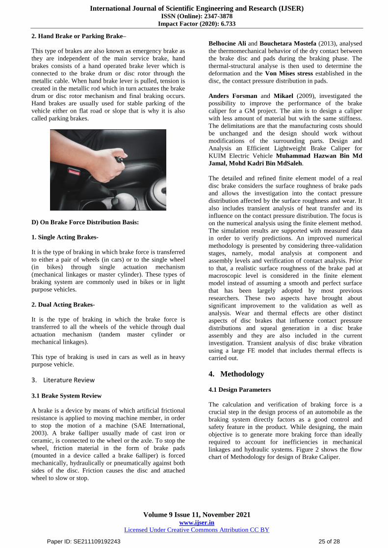
2. Hand Brake or Parking Brake–
This type of brakes are also known as emergency brake as
they are independent of the main service brake, hand
brakes consists of a hand operated brake lever which is
connected to the brake drum or disc rotor through the
metallic cable. When hand brake lever is pulled, tension is
created in the metallic rod which in turn actuates the brake
drum or disc rotor mechanism and final braking occurs.
Hand brakes are usually used for stable parking of the
vehicle either on flat road or slope that is why it is also
called parking brakes.
D) On Brake Force Distribution Basis:
1. Single Acting Brakes-
It is the type of braking in which brake force is transferred
to either a pair of wheels (in cars) or to the single wheel
(in bikes) through single actuation mechanism
(mechanical linkages or master cylinder). These types of
braking system are commonly used in bikes or in light
purpose vehicles.
2. Dual Acting Brakes-
It is the type of braking in which the brake force is
transferred to all the wheels of the vehicle through dual
actuation mechanism (tandem master cylinder or
mechanical linkages).
This type of braking is used in cars as well as in heavy
purpose vehicle.
3. Literature Review
3.1 Brake System Review
A brake is a device by means of which artificial frictional
resistance is applied to moving machine member, in order
to stop the motion of a machine (SAE International,
2003). A brake 6alliper usually made of cast iron or
ceramic, is connected to the wheel or the axle. To stop the
wheel, friction material in the form of brake pads
(mounted in a device called a brake 6alliper) is forced
mechanically, hydraulically or pneumatically against both
sides of the disc. Friction causes the disc and attached
wheel to slow or stop.
Belhocine Ali and Bouchetara Mostefa (2013), analysed
the thermomechanical behavior of the dry contact between
the brake disc and pads during the braking phase. The
thermal-structural analyse is then used to determine the
deformation and the Von Mises stress established in the
disc, the contact pressure distribution in pads.
Anders Forsman and Mikael (2009), investigated the
possibility to improve the performance of the brake
caliper for a GM project. The aim is to design a caliper
with less amount of material but with the same stiffness.
The delimitations are that the manufacturing costs should
be unchanged and the design should work without
modifications of the surrounding parts. Design and
Analysis an Efficient Lightweight Brake Caliper for
KUIM Electric Vehicle Muhammad Hazwan Bin Md
Jamal, Mohd Kadri Bin MdSaleh.
The detailed and refined finite element model of a real
disc brake considers the surface roughness of brake pads
and allows the investigation into the contact pressure
distribution affected by the surface roughness and wear. It
also includes transient analysis of heat transfer and its
influence on the contact pressure distribution. The focus is
on the numerical analysis using the finite element method.
The simulation results are supported with measured data
in order to verify predictions. An improved numerical
methodology is presented by considering three-validation
stages, namely, modal analysis at component and
assembly levels and verification of contact analysis. Prior
to that, a realistic surface roughness of the brake pad at
macroscopic level is considered in the finite element
model instead of assuming a smooth and perfect surface
that has been largely adopted by most previous
researchers. These two aspects have brought about
significant improvement to the validation as well as
analysis. Wear and thermal effects are other distinct
aspects of disc brakes that influence contact pressure
distributions and squeal generation in a disc brake
assembly and they are also included in the current
investigation. Transient analysis of disc brake vibration
using a large FE model that includes thermal effects is
carried out.
4. Methodology
4.1 Design Parameters
The calculation and verification of braking force is a
crucial step in the design process of an automobile as the
braking system directly factors as a good control and
safety feature in the product. While designing, the main
objective is to generate more braking force than ideally
required to account for inefficiencies in mechanical
linkages and hydraulic systems. Figure 2 shows the flow
chart of Methodology for design of Brake Caliper.
Paper ID: SE211109192243 25 of 28

International Journal of Scientific Engineering and Research (IJSER) ISSN (Online): 2347-3878
Impact Factor (2020): 6.733
Volume 9 Issue 11, November 2021 www.ijser.in
Licensed Under Creative Commons Attribution CC BY
Figure 2: Methodology for design of Caliper
4.2 Calculations
Figure 3:-Schematic representation of weight distribution
Following calculations are founding stones for designing
the braking system. They validate that design satisfies
necessary requirements:
1) Force applied on pedal (F) = 350N
2) Bore diameter of master cylinder (db) = 0.01905 m
3) Piston diameter of caliper (d) =0.032 m
4) Number of pistons (n) = 1
a) Bore area of master cylinder (Acb) =
5. Modeling of Caliper
Modeling of caliper was done as per requirement of the
piston diameter and assembly constraints in the wheel rim.
Paper ID: SE211109192243 26 of 28

International Journal of Scientific Engineering and Research (IJSER) ISSN (Online): 2347-3878
Impact Factor (2020): 6.733
Volume 9 Issue 11, November 2021 www.ijser.in
Licensed Under Creative Commons Attribution CC BY
Modeling was done on CATIA V5. Parametric modeling
was used in modeling of caliper.
Figure 4: CAD Model of Caliper
6. Finite Element Analysis
After the numerical calculations, all the parameters such
as bore diameter, seal groove, mounting, etc. are decided
and then the CAD modelling of the caliper was done using
CATIA V5. This model was analyzed by applying the
forces and pressure. Static structural analysis of the CAD
model was carried out in ANSYS 15.0. Following
material parameters were considered.
Table 1: Properties of AI 7075
6.1 MESING
The different mesh parameters like aspect ratio, skewness
were considered too improve the mesh quality. Out of the
different element types like hex dominant, sweep etc. tetra
elements were considered as they capture the curvatures
more accurately than in any other method. Proximity and
curvature was used in order to ensure finer mesh along the
curved regions and varying cross sections.
Figure 5:-Meshed Model of Brake Caliper
Caliper body is subjected to mainly following three loads:
1. Reaction on caliper due to the hydraulic pressure
applied on piston
2. Reaction on the caliper body due to clamping force
3. Frictional force on pad, transmitted to the friction pad
mounts.
Figure 6:-Loading conditions for Brake Caliper
The piston diameter and the bore diameter are calculated
according to required braking torque. This magnitude of
clamping force is applied on the rotor by the piston. T e
diameter and number of pistons can be iterated according
to equation depending upon the rim size i. e. space
availability. The piston diameter was selected to be 28
mm as per availability of rubber seal. The piston diameter
is nothing but the bore diameter of caliper. There is
clearance fit between the piston and the caliper bore in
absence of any seals. A step is provided at the bottom of
bore to prevent the back side of piston from touching the
bottom surface of caliper and to increase the space for
fluid to apply pressure.
Paper ID: SE211109192243 27 of 28

International Journal of Scientific Engineering and Research (IJSER) ISSN (Online): 2347-3878
Impact Factor (2020): 6.733
Volume 9 Issue 11, November 2021 www.ijser.in
Licensed Under Creative Commons Attribution CC BY
7. Results and Discussions
Figure 7:-Total Deformation of Brake Caliper
Figure 8:-Equivalent stress (von-misses) of a brake
caliper
Table 2:-Deformation & Stress variations
The stress results show that factor of safety for the
designed model is within limits Thermal stresses were
neglected as their effect is negligible. The parameters
decided could help in further lowering the manufacturing
cost and weight.
8. Conclusions
The following comments could be concluded:
1) Determination of the braking force is the most crucial
aspect to be considered while designing any braking
system. The generated braking force should always be
greater than the required braking force.
2) The calculation of required clamping force helps us to
decide the diameter and the number of pistons to be
used. Space and assembly constraints are also an
important factor while designing the caliper body.
3) The seal groove geometry is pivotal to the operation
of the caliper as it allows the piston to retract after the
required clamping force has been applied.
References
[1] Limpert, R. Brake design and safety, 2ndEdition,
Society of Automotive Engineers. Inc, Warrendale,
Pa.
[2] Belhocine, A. and Bouchetara, M. Study of The
Thermal Behaviour of Dry Contacts in The Brake
Discs, FME Transactions41 (59-65), 2013
[3] Forsman, A. and Bladh, M. Low weight brake caliper,
Master of Science Thesis, KTH Industrial
Engineering and Management013, MMK 2009: 10
[4] Santhosh sivan. K, Chandrasekar Sundaram,
Arangarajan. A and Dr. Senthil Kumar. P, Speed
dependent dual caliper action in disc brake.
International Journal of Mechanical Engineering and
Technology, 5 (10), 2014, pp.106–114.
[5] Glenn Kwabena Gyimah, Dong Chen and Ping
Huang, Dry Sliding Studies of Porosity On Sintered
Cu-Based Brake Materials. International Journal of
Mechanical Engineering and Technology, 4 (2), 2013,
pp.521–529.
[6] N. N. Kadu and N. Vivekanandan, Numerical and
Experimental Investigation of Squeal Noise
Generated In A Disc Brake System and Reduction of
It. International Journal of Mechanical Engineering
and Technology, 6 (9), 2015, pp.10–16
Paper ID: SE211109192243 28 of 28