Design and Analysis of Gimbal Thruster Configurations for...
10
International Journal of Computer Applications (0975 – 8887) Volume 112 – No. 6, February 2015 29 Design and Analysis of Gimbal Thruster Configurations for 3-Axis Satellite Attitude Control Farhad Fani Saberi Amirkabir University of Technology Space Science and Technology Institude Tehran, Iran Mehdi Zandieh Islamic Azad University of Boroujerd Department of Control Engineering Boroujerd, Iran ABSTRACT The satellite thruster’s configuration plays also an important role in providing the attitude control torques. In this paper, after discussing the gimbal thruster’s structure and its benefits, several configurations based on 2, 3 and 4 gimbal thrusters are investigated in order to identify the most suitable orientation that consume less fuel and raise reliability. Then, a 3-axis attitude controller based on proportional-derivative control law is applied to satellite dynamics under these configurations. All the configurations are analyzed in terms of their torque workspace (controllable directions), attitude control performances and gimbal angles changes. The results show that the 4-thrusters configuration is more reliable and gimbal angles changes are smoother. Keywords Gimbal reaction thrusters; 3-axis attitude control; Torque workspace; Gimbal angles; Proportional-derivative controller 1. INTRODUCTION Attitude control of a satellite has implemented by using various actuators. These actuators are Reaction and Momentum wheels, Control moment gyros, Reaction thrusters and Magnetic torquers. Reaction thrusters significantly used because they can product large torques which are required for attitude control. The level of thruster torque around a satellite axis depends not only on its thrust level but also on the torque-arm length. Thus selection of a suitable thruster depends primarily on its location on the satellite, and also on its inclination to the satellite body axes. In some cases, different torque levels might be needed around the three principal body axes, so the location of the thrusters and their direction must be carefully studied before a final configuration for the propulsion system. The location and direction of the thrusters is also affected by the location of the optical sensors and solar panels, which must not be damaged by the thrusters exhaust. Zuliana Ismail et al in [1] investigated several configurations based on three or four reaction wheels in order to identify the most suitable orientation that consumes a minimum power. The conventional PD-type (proportional-derivative) controller and PI-type (proportional-integral) controller are adopted for the satellite attitude and wheel angular momentum controls, respectively. But use of reaction thrusters has several advantages. Namely they can produce different torques in different intervals. Therefore, thrusters are more efficient rather than wheels in some usages. Sidi in [2] illustrated two configurations of satellite thrusters with six and four thrusters. Considering six fixed thrusters, each thruster is capable of acting only in one direction. Another thruster must be activated around the same axis on the opposite direction, in order to achieve a torque around the same axis on the opposite sign. Use of additional thrusters may cause increase satellite mass and fuel consumption. In other case, with four thrusters, the possibility of achieving linear velocity augmentation in desired body directions is no longer available. More researches have been achieved about actuators configuration scheme for attitude control system in recent years. These schemes have been applying in order to optimize fuel consumption [3]. For this purpose, using Gimbal thruster is offered. Gimbal system allows thrusters to rotate in the ideal direction to produce desired torques. Anzel. B. M et al in [4], Daryl K et al in [5] and Glogowski M. J in [6], have presented models with gimbal thrusters configuration. In these models, different tasks are considered for thrusters. But these models have problems in attitude control. The model is proposed by [4] use 8 fixed thrusters, in addition to 2 gimbal thrusters. As a result, this may be increases fuel consumption in some large maneuvers. According to thrusters configuration of the model is described by [5], thrusters are not capable of producing torques at anti- earth direction. This model needs other actuators like reaction wheels for complete attitude control. The thrusters task in the model proposed by [6] is station keeping. Designer has used single gimbal thrusters in this model. However, using additional thrusters increases accuracy, but also increases fuel consumption. Hence, it is necessary to obtain configuration method that 1 st well done control tasks and 2 nd decrease fuel consumption. On the other hand, reliability of attitude subsystem is one of the most considerable problems. For checking reliability, consider what the effect on product torques is in different directions while one or more thrusters or gimbal platforms get damaged. In spite of decreasing the number of thrusters, all the proposed configurations in this paper completely cover the torques workspace about the three axis of satellite compared to the previous models. Therefore, increase reliability of the configurations. Also, because stepper motors are used in gimbal systems, it should avoid corrosion of stepper motor segments with desired control algorithm. The thrust level is considered to be constant and equal for all thrusters. As a result, different torques provide with gimbal angles changes only. Whatever gimbal angle changes have less amplitude, gimbal hardwares would have less corrosion. The approach is employed for dividing torques. Then the gimbal angles get smooth changes. In this paper in section 2, gimbal thrusters and their benefits in comparison with fixed thrusters are discussed. In section 3, various configurations of gimbal thrusters and covering torques workspace are studied. In section 4, competency of configurations is analysed. In section 5, attitude dynamics and kinematics of satellite and pd control law are presented. In section 6, gimbal thruster control strategy is modeled and
Transcript of Design and Analysis of Gimbal Thruster Configurations for...
International Journal of Computer Applications (0975 – 8887)
Volume 112 – No. 6, February 2015
29
Design and Analysis of Gimbal Thruster Configurations
for 3-Axis Satellite Attitude Control
Farhad Fani Saberi Amirkabir University of Technology
Space Science and Technology Institude Tehran, Iran
Mehdi Zandieh Islamic Azad University of Boroujerd Department of Control Engineering
Boroujerd, Iran
ABSTRACT The satellite thruster’s configuration plays also an important
role in providing the attitude control torques. In this paper,
after discussing the gimbal thruster’s structure and its benefits,
several configurations based on 2, 3 and 4 gimbal thrusters are
investigated in order to identify the most suitable orientation
that consume less fuel and raise reliability. Then, a 3-axis
attitude controller based on proportional-derivative control
law is applied to satellite dynamics under these
configurations. All the configurations are analyzed in terms of
their torque workspace (controllable directions), attitude
control performances and gimbal angles changes. The results
show that the 4-thrusters configuration is more reliable and
gimbal angles changes are smoother.
Keywords Gimbal reaction thrusters; 3-axis attitude control; Torque
workspace; Gimbal angles; Proportional-derivative controller
1. INTRODUCTION Attitude control of a satellite has implemented by using
various actuators. These actuators are Reaction and
Momentum wheels, Control moment gyros, Reaction thrusters
and Magnetic torquers. Reaction thrusters significantly used
because they can product large torques which are required for
attitude control.
The level of thruster torque around a satellite axis depends not
only on its thrust level but also on the torque-arm length.
Thus selection of a suitable thruster depends primarily on its
location on the satellite, and also on its inclination to the
satellite body axes. In some cases, different torque levels
might be needed around the three principal body axes, so the
location of the thrusters and their direction must be carefully
studied before a final configuration for the propulsion system.
The location and direction of the thrusters is also affected by
the location of the optical sensors and solar panels, which
must not be damaged by the thrusters exhaust.
Zuliana Ismail et al in [1] investigated several configurations
based on three or four reaction wheels in order to identify the
most suitable orientation that consumes a minimum power.
The conventional PD-type (proportional-derivative) controller
and PI-type (proportional-integral) controller are adopted for
the satellite attitude and wheel angular momentum controls,
respectively. But use of reaction thrusters has several
advantages. Namely they can produce different torques in
different intervals. Therefore, thrusters are more efficient
rather than wheels in some usages.
Sidi in [2] illustrated two configurations of satellite thrusters
with six and four thrusters. Considering six fixed thrusters,
each thruster is capable of acting only in one direction.
Another thruster must be activated around the same axis on
the opposite direction, in order to achieve a torque around the
same axis on the opposite sign. Use of additional thrusters
may cause increase satellite mass and fuel consumption. In
other case, with four thrusters, the possibility of achieving
linear velocity augmentation in desired body directions is no
longer available.
More researches have been achieved about actuators
configuration scheme for attitude control system in recent
years. These schemes have been applying in order to optimize
fuel consumption [3]. For this purpose, using Gimbal thruster
is offered. Gimbal system allows thrusters to rotate in the
ideal direction to produce desired torques.
Anzel. B. M et al in [4], Daryl K et al in [5] and Glogowski
M. J in [6], have presented models with gimbal thrusters
configuration. In these models, different tasks are considered
for thrusters. But these models have problems in attitude
control. The model is proposed by [4] use 8 fixed thrusters, in
addition to 2 gimbal thrusters. As a result, this may be
increases fuel consumption in some large maneuvers.
According to thrusters configuration of the model is described
by [5], thrusters are not capable of producing torques at anti-
earth direction. This model needs other actuators like reaction
wheels for complete attitude control. The thrusters task in the
model proposed by [6] is station keeping. Designer has used
single gimbal thrusters in this model.
However, using additional thrusters increases accuracy, but
also increases fuel consumption. Hence, it is necessary to
obtain configuration method that 1st well done control tasks
and 2nd decrease fuel consumption. On the other hand,
reliability of attitude subsystem is one of the most
considerable problems. For checking reliability, consider what
the effect on product torques is in different directions while
one or more thrusters or gimbal platforms get damaged. In
spite of decreasing the number of thrusters, all the proposed
configurations in this paper completely cover the torques
workspace about the three axis of satellite compared to the
previous models. Therefore, increase reliability of the
configurations.
Also, because stepper motors are used in gimbal systems, it
should avoid corrosion of stepper motor segments with
desired control algorithm. The thrust level is considered to be
constant and equal for all thrusters. As a result, different
torques provide with gimbal angles changes only. Whatever
gimbal angle changes have less amplitude, gimbal hardwares
would have less corrosion. The approach is employed for
dividing torques. Then the gimbal angles get smooth changes.
In this paper in section 2, gimbal thrusters and their benefits in
comparison with fixed thrusters are discussed. In section 3,
various configurations of gimbal thrusters and covering
torques workspace are studied. In section 4, competency of
configurations is analysed. In section 5, attitude dynamics and
kinematics of satellite and pd control law are presented. In
section 6, gimbal thruster control strategy is modeled and
International Journal of Computer Applications (0975 – 8887)
Volume 112 – No. 6, February 2015
30
finally in section 7, 3-axis attitude control performance of
configurations under pd controller are presented.
2. GIMBAL THRUSTERS Gimbal is a rotary system about one axis and called
single-axis gimbal. This system consists of a small-angle
permanent magnet stepper motor coupled to a harmonic drive
speed reducer, with a large, rotating flange output member.
Nowadays several mechanisms are using for avoiding
corrosion in gimbal systems.
When there is necessity to move a load on two orthogonal
axes, two actuators can be combined to provide this
capability. These biaxial gimbals are designed in modular
fashion, making it easy to change units of either elevation or
azimuth angles. One of the properties of biaxial gimbal
system is covering all of the torque workspace around it by
using change 360 degrees of azimuth and 180 degrees of
elevation. Therefore, if thruster mounts on biaxial gimbal
platform, it can produce enough force in desired direction and
control the attitude and position of satellite. Figure 1
represents biaxial gimbal system.
Fig 1: a. biaxial gimbal scheme [7], b. gimbal platform
sample
Each gimbal mechanism includes a first gimbal for pivotal
movement about an axis parallel to the pitch, that is, Y-axis
and in a plane parallel to a plane defined by the roll (that is,
X-axis) and yaw (that is, Z-axis) axes. Each gimbal
mechanism also includes a second gimbal which is suitably
connected to the first gimbal for pivotal movement about an
axis parallel to the roll axis so as to have a component of
thrust directed out of the plane defined by the pitch and yaw
axes. The single gimbal thruster vector may be generated by
two fixed thrusters and the biaxial gimbal thruster vector may
be generated by three fixed thrusters as shown in Figure 2a
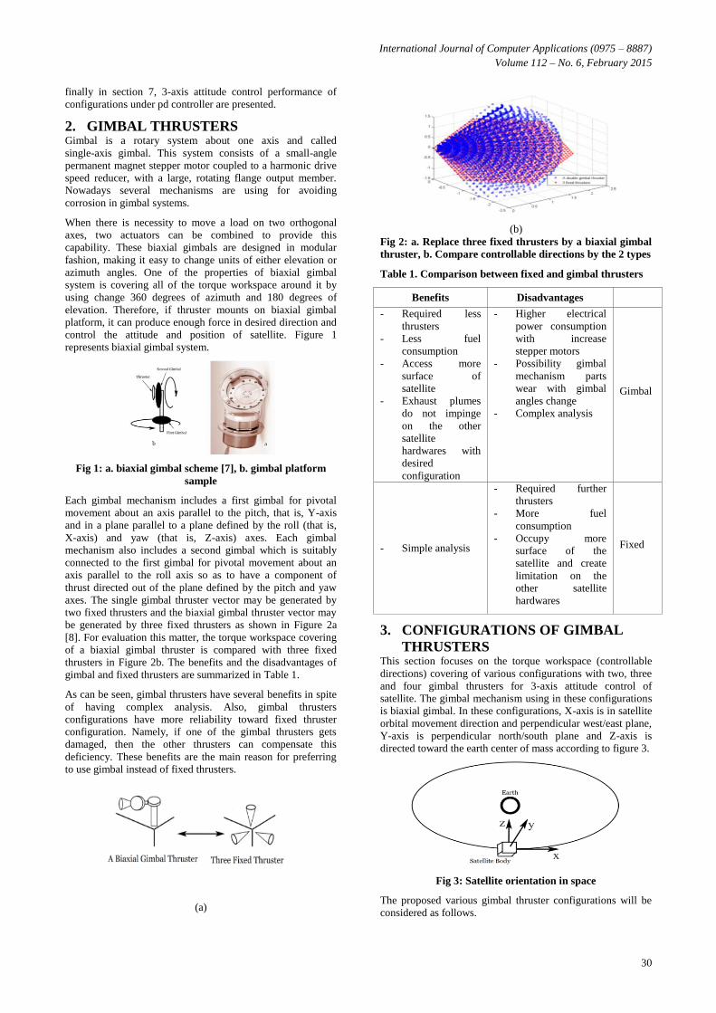
[8]. For evaluation this matter, the torque workspace covering
of a biaxial gimbal thruster is compared with three fixed
thrusters in Figure 2b. The benefits and the disadvantages of
gimbal and fixed thrusters are summarized in Table 1.
As can be seen, gimbal thrusters have several benefits in spite
of having complex analysis. Also, gimbal thrusters
configurations have more reliability toward fixed thruster
configuration. Namely, if one of the gimbal thrusters gets
damaged, then the other thrusters can compensate this
deficiency. These benefits are the main reason for preferring
to use gimbal instead of fixed thrusters.
(a)
(b)
Fig 2: a. Replace three fixed thrusters by a biaxial gimbal
thruster, b. Compare controllable directions by the 2 types
Table 1. Comparison between fixed and gimbal thrusters
Benefits Disadvantages
- Required less
thrusters
- Less fuel
consumption
- Access more
surface of
satellite
- Exhaust plumes
do not impinge
on the other
satellite
hardwares with
desired
configuration
- Higher electrical
power consumption
with increase
stepper motors
- Possibility gimbal
mechanism parts
wear with gimbal
angles change
- Complex analysis
Gimbal
- Simple analysis
- Required further
thrusters
- More fuel
consumption
- Occupy more
surface of the
satellite and create
limitation on the
other satellite
hardwares
Fixed
3. CONFIGURATIONS OF GIMBAL
THRUSTERS This section focuses on the torque workspace (controllable
directions) covering of various configurations with two, three
and four gimbal thrusters for 3-axis attitude control of
satellite. The gimbal mechanism using in these configurations
is biaxial gimbal. In these configurations, X-axis is in satellite
orbital movement direction and perpendicular west/east plane,
Y-axis is perpendicular north/south plane and Z-axis is
directed toward the earth center of mass according to figure 3.
Fig 3: Satellite orientation in space
The proposed various gimbal thruster configurations will be
considered as follows.
International Journal of Computer Applications (0975 – 8887)
Volume 112 – No. 6, February 2015
31
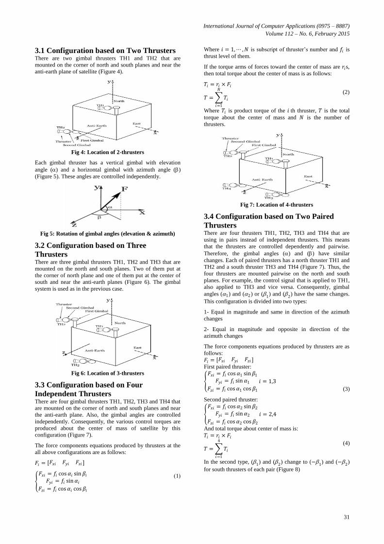
3.1 Configuration based on Two Thrusters There are two gimbal thrusters TH1 and TH2 that are
mounted on the corner of north and south planes and near the
anti-earth plane of satellite (Figure 4).
Fig 4: Location of 2-thrusters
Each gimbal thruster has a vertical gimbal with elevation
angle () and a horizontal gimbal with azimuth angle ()
(Figure 5). These angles are controlled independently.
Fig 5: Rotation of gimbal angles (elevation & azimuth)
3.2 Configuration based on Three
Thrusters There are three gimbal thrusters TH1, TH2 and TH3 that are
mounted on the north and south planes. Two of them put at
the corner of north plane and one of them put at the center of
south and near the anti-earth planes (Figure 6). The gimbal
system is used as in the previous case.
Fig 6: Location of 3-thrusters
3.3 Configuration based on Four
Independent Thrusters There are four gimbal thrusters TH1, TH2, TH3 and TH4 that
are mounted on the corner of north and south planes and near
the anti-earth plane. Also, the gimbal angles are controlled
independently. Consequently, the various control torques are
produced about the center of mass of satellite by this
configuration (Figure 7).
The force components equations produced by thrusters at the
all above configurations are as follows:
𝐹𝑖 = 𝐹𝑥𝑖 𝐹𝑦𝑖 𝐹𝑧𝑖
𝐹𝑥𝑖 = 𝑓𝑖 cos𝛼𝑖 sin𝛽𝑖𝐹𝑦𝑖 = 𝑓𝑖 sin𝛼𝑖
𝐹𝑧𝑖 = 𝑓𝑖 cos𝛼𝑖 cos𝛽𝑖
(1)
Where 𝑖 = 1,⋯ ,𝑁 is subscript of thruster’s number and 𝑓𝑖 is
thrust level of them.
If the torque arms of forces toward the center of mass are 𝑟𝑖s,
then total torque about the center of mass is as follows:
𝑇𝑖 = 𝑟𝑖 × 𝐹𝑖
𝑇 = 𝑇𝑖
𝑁
𝑖=1
(2)
Where 𝑇𝑖 is product torque of the 𝑖 th thruster, 𝑇 is the total
torque about the center of mass and 𝑁 is the number of
thrusters.
Fig 7: Location of 4-thrusters
3.4 Configuration based on Two Paired
Thrusters There are four thrusters TH1, TH2, TH3 and TH4 that are
using in pairs instead of independent thrusters. This means
that the thrusters are controlled dependently and pairwise.
Therefore, the gimbal angles () and () have similar
changes. Each of paired thrusters has a north thruster TH1 and
TH2 and a south thruster TH3 and TH4 (Figure 7). Thus, the
four thrusters are mounted pairwise on the north and south
planes. For example, the control signal that is applied to TH1,
also applied to TH3 and vice versa. Consequently, gimbal
angles (1) and (2) or (1) and (2) have the same changes.
This configuration is divided into two types:
1- Equal in magnitude and same in direction of the azimuth
changes
2- Equal in magnitude and opposite in direction of the
azimuth changes
The force components equations produced by thrusters are as
follows:
(3)
𝐹𝑖 = 𝐹𝑥𝑖 𝐹𝑦𝑖 𝐹𝑧𝑖 First paired thruster:
𝐹𝑥𝑖 = 𝑓𝑖 cos𝛼1 sin𝛽1
𝐹𝑦𝑖 = 𝑓𝑖 sin𝛼1
𝐹𝑧𝑖 = 𝑓𝑖 cos𝛼1 cos𝛽1
𝑖 = 1,3
Second paired thruster:
𝐹𝑥𝑖 = 𝑓𝑖 cos𝛼2 sin𝛽2
𝐹𝑦𝑖 = 𝑓𝑖 sin𝛼2
𝐹𝑧𝑖 = 𝑓𝑖 cos𝛼2 cos𝛽2
𝑖 = 2,4
And total torque about center of mass is:
(4)
𝑇𝑖 = 𝑟𝑖 × 𝐹𝑖
𝑇 = 𝑇𝑖
4
𝑖=1
In the second type, (1) and (2) change to (−1) and (−2)
for south thrusters of each pair (Figure 8)
International Journal of Computer Applications (0975 – 8887)
Volume 112 – No. 6, February 2015
32
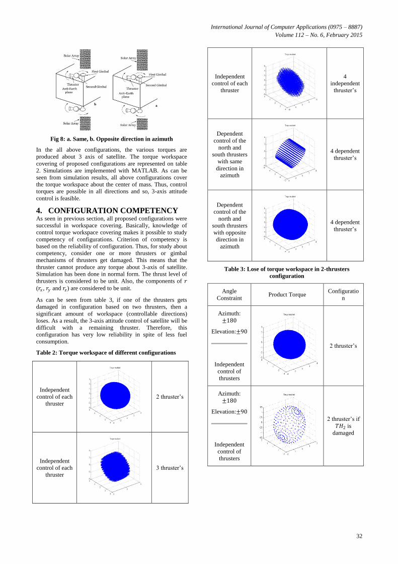
Fig 8: a. Same, b. Opposite direction in azimuth
In the all above configurations, the various torques are
produced about 3 axis of satellite. The torque workspace
covering of proposed configurations are represented on table
2. Simulations are implemented with MATLAB. As can be
seen from simulation results, all above configurations cover
the torque workspace about the center of mass. Thus, control
torques are possible in all directions and so, 3-axis attitude
control is feasible.
4. CONFIGURATION COMPETENCY As seen in previous section, all proposed configurations were
successful in workspace covering. Basically, knowledge of
control torque workspace covering makes it possible to study
competency of configurations. Criterion of competency is
based on the reliability of configuration. Thus, for study about
competency, consider one or more thrusters or gimbal
mechanisms of thrusters get damaged. This means that the
thruster cannot produce any torque about 3-axis of satellite.
Simulation has been done in normal form. The thrust level of
thrusters is considered to be unit. Also, the components of 𝑟
(𝑟𝑥 , 𝑟𝑦 and 𝑟𝑧) are considered to be unit.
As can be seen from table 3, if one of the thrusters gets
damaged in configuration based on two thrusters, then a
significant amount of workspace (controllable directions)
loses. As a result, the 3-axis attitude control of satellite will be
difficult with a remaining thruster. Therefore, this
configuration has very low reliability in spite of less fuel
consumption.
Table 2: Torque workspace of different configurations
2 thruster’s
Independent
control of each
thruster
3 thruster’s
Independent
control of each
thruster
4
independent
thruster’s
Independent
control of each
thruster
4 dependent
thruster’s
Dependent
control of the
north and
south thrusters
with same
direction in
azimuth
4 dependent
thruster’s
Dependent
control of the
north and
south thrusters
with opposite
direction in
azimuth
Table 3: Lose of torque workspace in 2-thrusters
configuration
Configuratio
n Product Torque
Angle
Constraint
2 thruster’s
Azimuth:
±180
Elevation:±90
Independent
control of
thrusters
2 thruster’s if
𝑇𝐻2 is
damaged
Azimuth:
±180
Elevation:±90
Independent
control of
thrusters
International Journal of Computer Applications (0975 – 8887)
Volume 112 – No. 6, February 2015
33
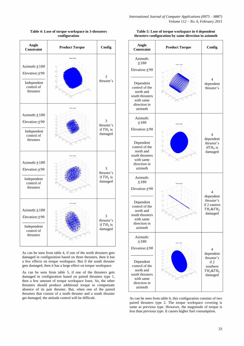
Table 4: Lose of torque workspace in 3-thrusters
configuration
Config Product Torque Angle
Constraint
3
thruster’s
Azimuth:±180
Elevation:±90
Independent
control of
thrusters
3
thruster’s
if 𝑇𝐻1 is
damaged
Azimuth:±180
Elevation:±90
Independent
control of
thrusters
3
thruster’s
if 𝑇𝐻2 is
damaged
Azimuth:±180
Elevation:±90
Independent
control of
thrusters
3
thruster’s
if 𝑇𝐻3 is
damaged
Azimuth:±180
Elevation:±90
Independent
control of
thrusters
As can be seen from table 4, if one of the north thrusters gets
damaged in configuration based on three thrusters, then it has
a few effects on torque workspace. But if the south thruster
gets damaged, then it has a large effect on torque workspace.
As can be seen from table 5, if one of the thrusters gets
damaged in configuration based on paired thrusters type 1,
then a few amount of torque workspace loses. So, the other
thrusters should produce additional torque to compensate
absence of its pair thruster. But, when one of the paired
thrusters that consist of a north thruster and a south thruster
get damaged, the attitude control will be difficult.
Table 5: Lose of torque workspace in 4 dependent
thrusters configuration by same direction in azimuth
Config Product Torque Angle
Constraint
4
dependent
thruster’s
Azimuth:
±180
Elevation:±90
Dependent
control of the
north and
south thrusters
with same
direction in
azimuth
4
dependent
thruster’s
if𝑇𝐻4 is
damaged
Azimuth:
±180
Elevation:±90
Dependent
control of the
north and
south thrusters
with same
direction in
azimuth
4
dependent
thruster’s
if 2 eastern
𝑇𝐻1&𝑇𝐻3
damaged
Azimuth:
±180
Elevation:±90
Dependent
control of the
north and
south thrusters
with same
direction in
azimuth
4
dependent
thruster’s
if 2
southern
𝑇𝐻3&𝑇𝐻4
damaged
Azimuth:
±180
Elevation:±90
Dependent
control of the
north and
south thrusters
with same
direction in
azimuth
As can be seen from table 6, this configuration consists of two
paired thrusters type 2. The torque workspace covering is
same as previous type. However, the magnitude of torque is
less than previous type. It causes higher fuel consumption.
International Journal of Computer Applications (0975 – 8887)
Volume 112 – No. 6, February 2015
34
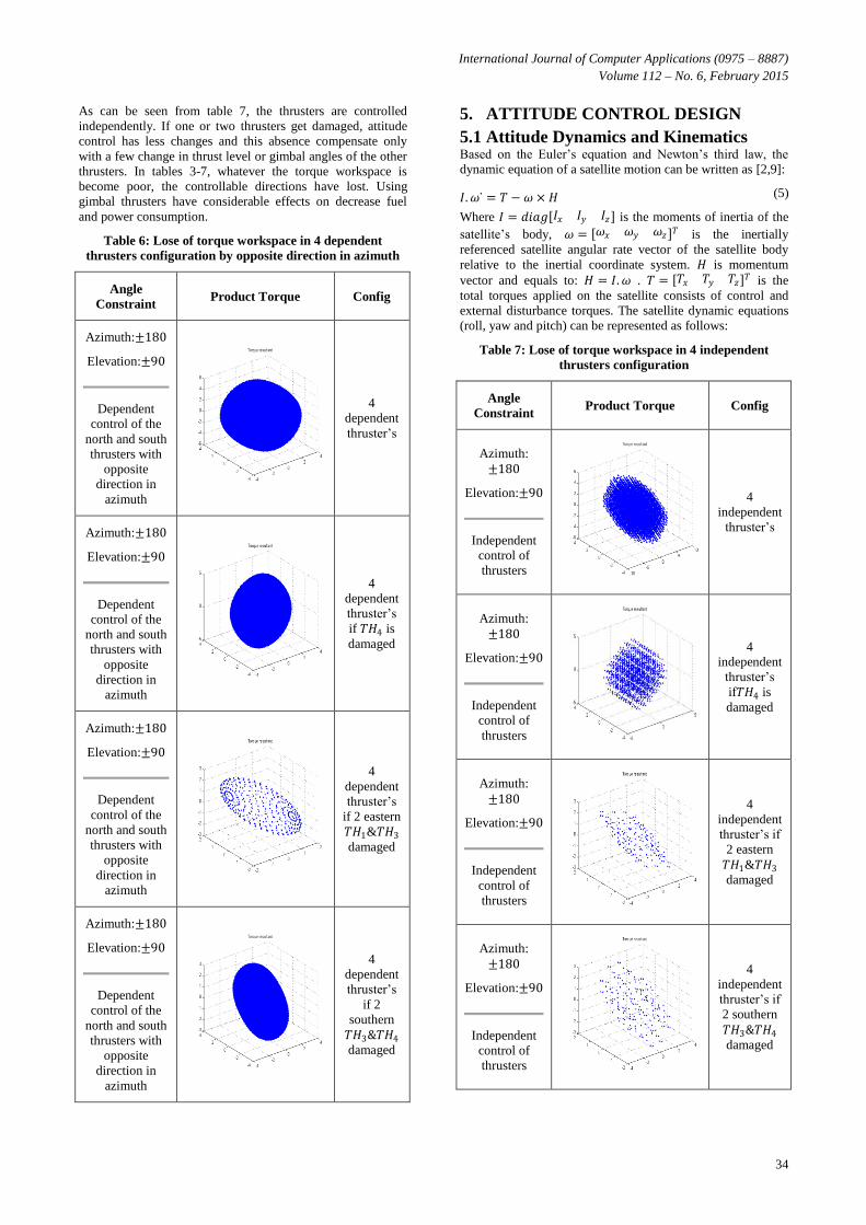
As can be seen from table 7, the thrusters are controlled
independently. If one or two thrusters get damaged, attitude
control has less changes and this absence compensate only
with a few change in thrust level or gimbal angles of the other
thrusters. In tables 3-7, whatever the torque workspace is
become poor, the controllable directions have lost. Using
gimbal thrusters have considerable effects on decrease fuel
and power consumption.
Table 6: Lose of torque workspace in 4 dependent
thrusters configuration by opposite direction in azimuth
Config Product Torque Angle
Constraint
4
dependent
thruster’s
Azimuth:±180
Elevation:±90
Dependent
control of the
north and south
thrusters with
opposite
direction in
azimuth
4
dependent
thruster’s
if 𝑇𝐻4 is
damaged
Azimuth:±180
Elevation:±90
Dependent
control of the
north and south
thrusters with
opposite
direction in
azimuth
4
dependent
thruster’s
if 2 eastern
𝑇𝐻1&𝑇𝐻3
damaged
Azimuth:±180
Elevation:±90
Dependent
control of the
north and south
thrusters with
opposite
direction in
azimuth
4
dependent
thruster’s
if 2
southern
𝑇𝐻3&𝑇𝐻4
damaged
Azimuth:±180
Elevation:±90
Dependent
control of the
north and south
thrusters with
opposite
direction in
azimuth
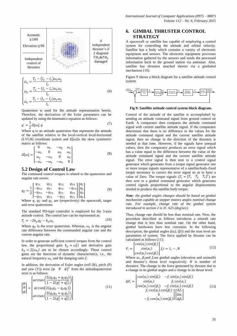
5. ATTITUDE CONTROL DESIGN
5.1 Attitude Dynamics and Kinematics Based on the Euler’s equation and Newton’s third law, the
dynamic equation of a satellite motion can be written as [2,9]:
(5) 𝐼.𝜔 ̇ = 𝑇 − 𝜔 × 𝐻
Where 𝐼 = 𝑑𝑖𝑎𝑔 𝐼𝑥 𝐼𝑦 𝐼𝑧 is the moments of inertia of the
satellite’s body, 𝜔 = 𝜔𝑥 𝜔𝑦 𝜔𝑧 𝑇 is the inertially
referenced satellite angular rate vector of the satellite body
relative to the inertial coordinate system. 𝐻 is momentum
vector and equals to: 𝐻 = 𝐼.𝜔 . 𝑇 = 𝑇𝑥 𝑇𝑦 𝑇𝑧 𝑇 is the
total torques applied on the satellite consists of control and
external disturbance torques. The satellite dynamic equations
(roll, yaw and pitch) can be represented as follows:
Table 7: Lose of torque workspace in 4 independent
thrusters configuration
Config Product Torque Angle
Constraint
4
independent
thruster’s
Azimuth:
±180
Elevation:±90
Independent
control of
thrusters
4
independent
thruster’s
if𝑇𝐻4 is
damaged
Azimuth:
±180
Elevation:±90
Independent
control of
thrusters
4
independent
thruster’s if
2 eastern
𝑇𝐻1&𝑇𝐻3
damaged
Azimuth:
±180
Elevation:±90
Independent
control of
thrusters
4
independent
thruster’s if
2 southern
𝑇𝐻3&𝑇𝐻4
damaged
Azimuth:
±180
Elevation:±90
Independent
control of
thrusters
International Journal of Computer Applications (0975 – 8887)
Volume 112 – No. 6, February 2015
35
4
independent
thruster’s if
2 diagonal
𝑇𝐻2&𝑇𝐻3
damaged
Azimuth:
±180
Elevation:±90
Independent
control of
thrusters
(6)
�̇�𝑥 =
𝑇𝑥 − 𝐼𝑦 − 𝐼𝑧 𝜔𝑧𝜔𝑦
𝐼𝑥
�̇�𝑦 =𝑇𝑦 − 𝐼𝑧 − 𝐼𝑥 𝜔𝑥𝜔𝑧
𝐼𝑦
�̇�𝑧 =𝑇𝑧 − (𝐼𝑥 − 𝐼𝑦)𝜔𝑦𝜔𝑥
𝐼𝑧
Quaternion is used for the attitude representation herein.
Therefore, the derivatives of the Euler parameters can be
updated by using the kinematics equation as follows:
(7) 𝑞 ̇ =1
2𝛺[𝜔]. 𝑞
Where q is an attitude quaternion that represents the attitude
of the satellite relative to the local-vertical–local-horizontal
(LVLH) coordinate system and Ω 𝜔 is the skew symmetric
matrix as follows:
(8) 𝛺 𝜔 =
0 𝜔𝑧 −𝜔𝑦 𝜔𝑥−𝜔𝑧 0 𝜔𝑥 𝜔𝑦𝜔𝑦 −𝜔𝑥 0 𝜔𝑧−𝜔𝑥 −𝜔𝑦 −𝜔𝑧 0
5.2 Design of Control Law The command control torques is related to the quaternion and
angular rate errors:
(9) 𝑞𝐸 =1
2
𝑞𝑇1 𝑞𝑇2 𝑞𝑇3 𝑞𝑇4
−𝑞𝑇2 𝑞𝑇1 𝑞𝑇4 −𝑞𝑇3
−𝑞𝑇3 −𝑞𝑇4 𝑞𝑇1 𝑞𝑇2
−𝑞𝑇4 𝑞𝑇3 −𝑞𝑇2 𝑞𝑇1
𝑞1
𝑞2
𝑞3
𝑞4
Where 𝑞, 𝑞𝑇 and 𝑞𝐸 are (respectively) the spacecraft, target
and error quaternions.
The standard PD-type controller is employed for the 3-axis
attitude control. The control law can be represented as:
(10) 𝑇𝑐 = −2𝑘𝑝𝑞𝐸 − 𝑘𝑑𝜔𝑒
Where 𝑞𝐸 is the error quaternion. Whereas, 𝜔𝑒 is the angular
rate difference between the commanded angular rate and the
current angular rate.
In order to generate sufficient control torques from the control
law, the proportional gain 𝑘𝑝 = 𝜔𝑛2𝐼 and derivative gain
𝑘𝑑 = 2𝜉𝜔𝑛 𝐼 are to be chosen accordingly. These control
gains are the functions of dynamic characteristics, i.e., the
natural frequency 𝜔𝑛 and the damping ratio 𝜉.
In addition, the derivation of Euler angles (roll (R), pitch (P)
and yaw (Y)) error 𝜑 𝜃 𝜓 𝑇 from the attitudequaternion
error is as follows:
(11)
𝜑𝜃𝜓 =
𝑎𝑟𝑐𝑡𝑎𝑛
2(𝑞1𝑞4 + 𝑞2𝑞3)
1 − 2 𝑞12 + 𝑞2
2
𝑎𝑟𝑐𝑠𝑖𝑛 2 𝑞4𝑞2 − 𝑞3𝑞1
𝑎𝑟𝑐𝑡𝑎𝑛 2 𝑞4𝑞3 + 𝑞1𝑞2
1 − 2 𝑞22 + 𝑞3
2
6. GIMBAL THRUSTER CONTROL
STRATEGY A spacecraft or satellite has capable of employing a control
system for controlling the attitude and orbital velocity.
Satellite has a body which contains a variety of electronic
equipment and sensors. The electronic equipment processes
information gathered by the sensors and sends the processed
information back to the ground station via antennae. Also,
satellite has thrusters attached thereto via a gimbaled
mechanism [10].
Figure 9 shows a block diagram for a satellite attitude control
system.
Fig 9: Satellite attitude control system block diagram.
Control of the attitude of the satellite is accomplished by
sending an attitude command signal from ground control on
Earth. A comparator then compares the attitude command
signal with current satellite attitude signal. If the comparator
determines that there is no difference in the values for the
attitude command signal and the current satellite attitude
signal, then no change in the direction of the thrusters is
needed at that time. However, if the signals have unequal
values, then the comparator produces an error signal which
has a value equal to the difference between the value of the
attitude command signal and the current satellite attitude
signal. The error signal is then sent to a control signal
generator which generates from a torque signal generator one
or more torque signals representative of a satellite/body-fixed
torque necessary to correct the error signal so as to have a
value of Zero. The torque signals (𝑇𝑐 = 𝑇𝑥 𝑇𝑦 𝑇𝑧 𝑇) are
then sent to a gimbal command generator which generates
control signals proportional to the angular displacements
needed to produce the satellite body torque.
Note: the gimbal angles changes should be based on gimbal
mechanism capable at stepper motors angles nominal change
rate. For example, change rate of the gimbal system
introduced in section 2 is 31. 625 (deg/sec).
Thus, change rate should be less than nominal rate. Now, the
procedure described as follows introduces a smooth rate
change that is less than nominal rate. On the other hand,
gimbal hardwares have less corrosion. In the following
description, the gimbal angles ((), ()) and the trust level are
parameters of system. The force applied by thruster can be
calculated as follows [11]:
(12) 𝐹𝑖 =
𝑐𝑜𝑠 𝛼𝑖 𝑠𝑖𝑛 𝛽𝑖
𝑠𝑖𝑛 𝛼𝑖
𝑐𝑜𝑠 𝛼𝑖 𝑐𝑜𝑠 𝛽𝑖 𝑓𝑖𝑖 = 1,⋯ ,𝑁
Where 𝛼𝑖 , 𝛽𝑖and 𝑓𝑖are gimbal angles (elevation and azimuth)
and thruster’s thrust level respectively. 𝑁 is number of
thrusters. The change in the force generated by thruster due to
a change in its gimbal angles and a change in its thrust level:
(13)
∆𝐹𝑖 =
𝑐𝑜𝑠 𝛼𝑖 𝑠𝑖𝑛 𝛽𝑖 −𝑓𝑖 𝑠𝑖𝑛 𝛼𝑖 𝑠𝑖𝑛 𝛽𝑖
𝑠𝑖𝑛 𝛼𝑖 𝑓𝑖 𝑐𝑜𝑠 𝛼𝑖
𝑐𝑜𝑠 𝛼𝑖 𝑐𝑜𝑠 𝛽𝑖 −𝑓𝑖 𝑠𝑖𝑛 𝛼𝑖 𝑐𝑜𝑠 𝛽𝑖
𝑓𝑖 𝑐𝑜𝑠 𝛼𝑖 𝑐𝑜𝑠 𝛽𝑖
0−𝑓𝑖 𝑐𝑜𝑠 𝛼𝑖 𝑠𝑖𝑛 𝛽𝑖
∆𝑓𝑖∆𝛼𝑖∆𝛽𝑖
International Journal of Computer Applications (0975 – 8887)
Volume 112 – No. 6, February 2015
36
The torque may be controlled by commanding changes in the
gimbal angles, without commanding changes in thrusts. The
change in torque of thruster due to a change in its gimbal
angles may be calculated according to equation below:
(14)
∆𝑇𝑖 =
0 −𝑦𝑖 𝑥𝑖𝑦𝑖 0 −𝑧𝑖−𝑥𝑖 𝑧𝑖 0
−𝑓𝑖 𝑠𝑖𝑛 𝛼𝑖 𝑠𝑖𝑛 𝛽𝑖 𝑓𝑖 𝑐𝑜𝑠 𝛼𝑖 𝑐𝑜𝑠 𝛽𝑖
𝑓𝑖 𝑐𝑜𝑠 𝛼𝑖 0
−𝑓𝑖 𝑠𝑖𝑛 𝛼𝑖 𝑐𝑜𝑠 𝛽𝑖 −𝑓𝑖 𝑐𝑜𝑠 𝛼𝑖 𝑠𝑖𝑛 𝛽𝑖 ∆𝛼𝑖∆𝛽𝑖
= 𝐴𝑖∆𝑔𝑖𝑖 = 1,⋯ ,𝑁 Where 𝐴𝑖 is a 3 × 2 matrix, ∆𝑔𝑖 is a 2 × 1 vector containing
∆𝛼𝑖 and ∆𝛽𝑖 , and 𝑟𝑖 = 𝑥𝑖 𝑦𝑖 𝑧𝑖 is the vector from
thesatellite center-of-mass to the gimbal platform.
The total change in torque is the sum of the change in torque
due to thrusters:
(15) ∆𝑇 = ∆𝑇𝑖
𝑁
𝑖=1
= 𝐴𝑖∆𝑔𝑖
𝑁
𝑖=1
= 𝐴1 ⋯ 𝐴𝑁
∆𝑔1
⋮
∆𝑔𝑁
= 𝐴∆𝑔𝑡
Where 𝐴 is a matrix and ∆𝑔𝑡 is a vector. Each control cycle, a
commanded torque change ∆𝑇𝑐 may be determined according
to equation (16)
(16) ∆𝑇𝑐 = 𝑇𝑐 − 𝑇𝑔
Where 𝑇𝑐 is the sum of the attitude control torque demand and
𝑇𝑔 is the total torque produced by thrusters. The ∆𝑔𝑡 that
provides therequired ∆𝑇𝑐 is then calculated according to
equation (17)
(17) ∆𝑔𝑡 = 𝑃∆𝑇𝑐
Where P is the pseudo-inverse of A computed as:
(18) 𝑃 = 𝐴𝑇 𝐴𝐴𝑇 −1
The torque control vector ∆𝑔𝑡 , calculated using Equation (17)
is a vector containing the change in gimbal angles for
thrusters. Each control cycle, this change sum with gimbal
angles:
(18) 𝑔𝑛𝑒𝑤 = 𝑔𝑡 + ∆𝑔𝑡 =
𝛼𝑖𝛽𝑖⋮𝛼𝑖𝛽𝑖
+
∆𝛼𝑖∆𝛽𝑖⋮
∆𝛼𝑖∆𝛽𝑖
And the total torque produced by thrusters:
(19) 𝑇𝑔 = 𝑟𝑖 × 𝐹𝑖
𝑁
𝑖=1
The control cycle is repeated until the attitude error reaches to
zero and does not require changing gimbal angles.
The control signals 36 are then sent to the thruster assemblies
which angle one or more of the thrusters so that torques
𝑇𝑐 = 𝑇𝑥 𝑇𝑦 𝑇𝑧 𝑇 are applied to the satellite to correct the
attitude.
The proposed gimbal control system make the controller
capable to control the satellite even with two low thrust
thrusters.
7. ATTITUDE PERFORMANCE OF
VARIOUS CONFIGURATIONS As seen in previous section, the torque may be controlled by
commanding changes in the gimbal angles, without
commanding changes in thrusts. In this section, changes in the
gimbal angles are studied under pd (proportional-derivative)
controller. But, the control law and the optimal changes in
gimbal angles depend on thruster’s configuration. One of the
other important problems is feasibility in capable of stepper
motor’s angles change, i.e. the change rate must be less than
nominal rate.
The standard pd control law is applied to satellite dynamics
under two, three and four gimbal thrusters configuration.
Table 8. Satellite and pd controller parameters
moments of inertia
𝐼𝑥 = 1, 𝐼𝑦 = 0.5,
𝐼𝑧= 0.7 𝑘𝑔𝑚2
Proportional and
derivative gains 𝑘𝑝𝑥 = 1,𝑘𝑝𝑦 = 0.5, 𝑘𝑝𝑧 = 0.7 𝑁𝑚 𝑟𝑎𝑑
𝑘𝑑𝑥 = 2,𝑘𝑑𝑦 = 1, 𝑘𝑑𝑧 = 1.4 𝑁𝑚𝑠 𝑟𝑎𝑑
Attitude maneuver
𝜑𝜃𝜓 =
000 →
40−40−60
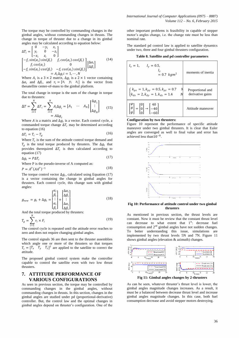
Configuration by two thrusters:
Figure 10 represent the performance of specific attitude
maneuver under two gimbal thrusters. It is clear that Euler
angles are converged as well to final value and error has
achieved less than10−8.
Fig 10: Performance of attitude control under two gimbal
thrusters
As mentioned in previous section, the thrust levels are
constant. Now it must be review that the constant thrust level
can decrease to what extent that 1st: decrease fuel
consumption and 2nd gimbal angles have not sudden changes.
To better understanding this issue, simulations are
implemented by two thrust levels 5N and 7N. Figure 11
shows gimbal angles (elevation & azimuth) changes.
Fig 11: Gimbal angles changes by 2-thrusters
As can be seen, whatever thruster’s thrust level is lower, the
gimbal angles magnitude changes increases. As a result, it
must be a balanced between decrease thrust level and increase
gimbal angles magnitude changes. In this case, both fuel
consumption decrease and avoid stepper motors destroying.
International Journal of Computer Applications (0975 – 8887)
Volume 112 – No. 6, February 2015
37
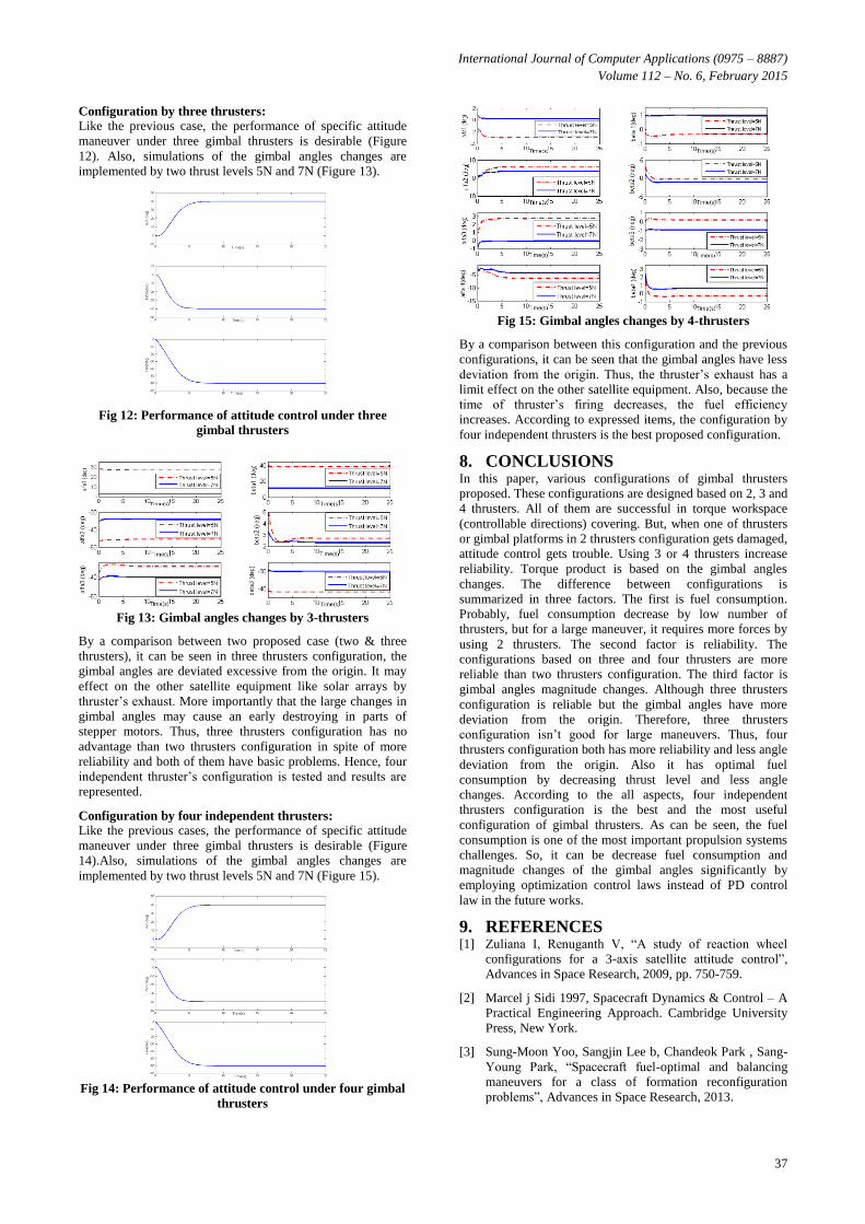
Configuration by three thrusters:
Like the previous case, the performance of specific attitude
maneuver under three gimbal thrusters is desirable (Figure
12). Also, simulations of the gimbal angles changes are
implemented by two thrust levels 5N and 7N (Figure 13).
Fig 12: Performance of attitude control under three
gimbal thrusters
Fig 13: Gimbal angles changes by 3-thrusters
By a comparison between two proposed case (two & three
thrusters), it can be seen in three thrusters configuration, the
gimbal angles are deviated excessive from the origin. It may
effect on the other satellite equipment like solar arrays by
thruster’s exhaust. More importantly that the large changes in
gimbal angles may cause an early destroying in parts of
stepper motors. Thus, three thrusters configuration has no
advantage than two thrusters configuration in spite of more
reliability and both of them have basic problems. Hence, four
independent thruster’s configuration is tested and results are
represented.
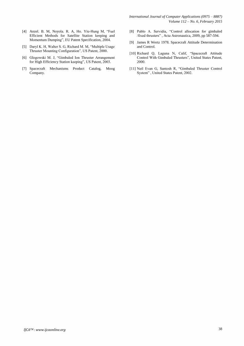
Configuration by four independent thrusters:
Like the previous cases, the performance of specific attitude
maneuver under three gimbal thrusters is desirable (Figure
14).Also, simulations of the gimbal angles changes are
implemented by two thrust levels 5N and 7N (Figure 15).
Fig 14: Performance of attitude control under four gimbal
thrusters
Fig 15: Gimbal angles changes by 4-thrusters
By a comparison between this configuration and the previous
configurations, it can be seen that the gimbal angles have less
deviation from the origin. Thus, the thruster’s exhaust has a
limit effect on the other satellite equipment. Also, because the
time of thruster’s firing decreases, the fuel efficiency
increases. According to expressed items, the configuration by
four independent thrusters is the best proposed configuration.
8. CONCLUSIONS In this paper, various configurations of gimbal thrusters
proposed. These configurations are designed based on 2, 3 and
4 thrusters. All of them are successful in torque workspace
(controllable directions) covering. But, when one of thrusters
or gimbal platforms in 2 thrusters configuration gets damaged,
attitude control gets trouble. Using 3 or 4 thrusters increase
reliability. Torque product is based on the gimbal angles
changes. The difference between configurations is
summarized in three factors. The first is fuel consumption.
Probably, fuel consumption decrease by low number of
thrusters, but for a large maneuver, it requires more forces by
using 2 thrusters. The second factor is reliability. The
configurations based on three and four thrusters are more
reliable than two thrusters configuration. The third factor is
gimbal angles magnitude changes. Although three thrusters
configuration is reliable but the gimbal angles have more
deviation from the origin. Therefore, three thrusters
configuration isn’t good for large maneuvers. Thus, four
thrusters configuration both has more reliability and less angle
deviation from the origin. Also it has optimal fuel
consumption by decreasing thrust level and less angle
changes. According to the all aspects, four independent
thrusters configuration is the best and the most useful
configuration of gimbal thrusters. As can be seen, the fuel
consumption is one of the most important propulsion systems
challenges. So, it can be decrease fuel consumption and
magnitude changes of the gimbal angles significantly by
employing optimization control laws instead of PD control
law in the future works.
9. REFERENCES [1] Zuliana I, Renuganth V, “A study of reaction wheel
configurations for a 3-axis satellite attitude control”,
Advances in Space Research, 2009, pp. 750-759.
[2] Marcel j Sidi 1997, Spacecraft Dynamics & Control – A
Practical Engineering Approach. Cambridge University
Press, New York.
[3] Sung-Moon Yoo, Sangjin Lee b, Chandeok Park , Sang-
Young Park, “Spacecraft fuel-optimal and balancing
maneuvers for a class of formation reconfiguration
problems”, Advances in Space Research, 2013.
International Journal of Computer Applications (0975 – 8887)
Volume 112 – No. 6, February 2015
38
[4] Anzel. B. M, Noyola. R. A, Ho. Yiu-Hung M, “Fuel
Efficient Methods for Satellite Station keeping and
Momentum Dumping”, EU Patent Specification, 2004.
[5] Daryl K. H, Walter S. G, Richard M. M, “Multiple Usage
Thruster Mounting Configuration”, US Patent, 2000.
[6] Glogowski M. J, “Gimbaled Ion Thruster Arrangement
for High Efficiency Station keeping”, US Patent, 2003.
[7] Spacecraft Mechanisms Product Catalog, Moog
Company.
[8] Pablo A. Servidia, “Control allocation for gimbaled
/fixed thrusters” , Acta Astronautica, 2009, pp 587-594.
[9] James R Wertz 1978. Spacecraft Attitude Determination
and Control.
[10] Richard Q, Laguna N, Calif, “Spacecraft Attitude
Control With Gimbaled Thrusters”, United States Patent,
2000.
[11] Neil Evan G, Santosh R, “Gimbaled Thruster Control
System” , United States Patent, 2002.
IJCATM : www.ijcaonline.org


![Volume102,Number6,November–December1997 …...Volume102,Number6,November–December1997 JournalofResearchoftheNationalInstituteofStandardsandTechnology [J.Res.Natl.Inst.Stand.Technol.102,647(1997)]](https://static.fdocuments.in/doc/165x107/5e6c8ae574ec1e6745457f75/volume102number6novemberadecember1997-volume102number6novemberadecember1997.jpg)