
Design and analysis of gasket cutting machine
13
p-ISSN : 2335-1357 e-ISSN : 2437-1122 Mediterranean Journal of Modeling and Simulation Med. J. Model. Simul. 05 (2016) 046-058 Design and analysis of gasket cutting machine Vipin V. Gopal a , Lokavarapu Bhaskara Rao a a School of Mechanical and Building Science, VIT University, Chennai Campus, Vandalur-Kelambakkam Road, Chennai, Tamil Nadu, India ARTICLE INFO Article history : Received October 2015 Accepted February 2016 Keywords : Gasket ; Fully automated ; Idealization of system ; Cost analysis ; Design for manufacturing and assem- bly. ABSTRACT Paper is about the design and analysis of the optimized gasket cutting machine which can be provide to the companies where there is use of gaskets at a certain interval of time. The paper contain the cost optimized machine which is provide at a much lower cost as compared to the machines presently available in the market. This machine can be specically used for the boiler and refrigeration companies where the gaskets are used to avoid the leakage due to the joining of two di/erent diametric pipes. Inspite of giving a large order of gaskets, they can prepare the same at small rate whenever needed at the location. c 2016 LESI. All rights reserved. 1. Introduction Gasket is a mechanical seal that is used for lling the space between two surfaces, usually to prevent the leakage between the two objects which is under compression. Gaskets are used to cover irregularities on mating surfaces of machine parts. They are commonly produced by cutting from sheet materials such as paper, rubber, silicon, metal, ber and asbestos lining material (L. Angrisani et al, 1999). The use of gaskets in automobiles, chemical plants, power plants, ship building yard, breweries, dye, stu/ plants, oil reneries, refrigeration plants, allied industries, assembly lines in refrigeration plants etc (Trelleborg sealing solution,2011). In refrigeration and air conditioning system during assembly of the pipes di/erent diameters pipes are bolted together (David A. Nash et al, 2009 ; Dennis R. Moss et al, 2012). During joining the two di/erent diameters pipe there is a possibility of leakage due to improper contact between them. During assembly there is a major problem of leakage of refrigerant leads to decrees the internal pressure and ow rate of refrigerant. These gaskets get degraded after a specic life time. And for the replacement the companies have to order the same in a bilk. So, rather than buying the gasket the company can have one of the machines so that they can make the gasket whenever needed. But in market the gasket machine Email : [email protected] 46
Transcript of Design and analysis of gasket cutting machine

p-ISSN : 2335-1357 e-ISSN : 2437-1122
Mediterranean Journal of Modeling andSimulation
Med. J. Model. Simul. 05 (2016) 046-058
M J
M S
Design and analysis of gasket cutting machine
Vipin V. Gopal a �, Lokavarapu Bhaskara Rao a
a School of Mechanical and Building Science, VIT University, Chennai Campus,Vandalur-Kelambakkam Road, Chennai, Tamil Nadu, India
ARTICLE INFO
Article history :Received October 2015Accepted February 2016
Keywords :Gasket ;Fully automated ;Idealization of system ;Cost analysis ;Design for manufacturing and assem-bly.
ABSTRACT
Paper is about the design and analysis of the optimized gasket cuttingmachine which can be provide to the companies where there is use ofgaskets at a certain interval of time. The paper contain the cost optimizedmachine which is provide at a much lower cost as compared to the machinespresently available in the market. This machine can be speci�cally used forthe boiler and refrigeration companies where the gaskets are used to avoidthe leakage due to the joining of two di¤erent diametric pipes. Inspite ofgiving a large order of gaskets, they can prepare the same at small ratewhenever needed at the location.
c 2016 LESI. All rights reserved.
1. Introduction
Gasket is a mechanical seal that is used for �lling the space between two surfaces, usuallyto prevent the leakage between the two objects which is under compression. Gaskets areused to cover irregularities on mating surfaces of machine parts. They are commonlyproduced by cutting from sheet materials such as paper, rubber, silicon, metal, �ber andasbestos lining material (L. Angrisani et al, 1999).The use of gaskets in automobiles, chemical plants, power plants, ship building yard,
breweries, dye, stu¤ plants, oil re�neries, refrigeration plants, allied industries, assemblylines in refrigeration plants etc (Trelleborg sealing solution,2011). In refrigeration and airconditioning system during assembly of the pipes di¤erent diameters pipes are boltedtogether (David A. Nash et al, 2009 ; Dennis R. Moss et al, 2012). During joining thetwo di¤erent diameters pipe there is a possibility of leakage due to improper contactbetween them. During assembly there is a major problem of leakage of refrigerant leadsto decrees the internal pressure and �ow rate of refrigerant. These gaskets get degradedafter a speci�c life time. And for the replacement the companies have to order the samein a bilk. So, rather than buying the gasket the company can have one of the machinesso that they can make the gasket whenever needed. But in market the gasket machine
�Email : [email protected]
46

V. V. Gopal et al./ Med. J. Model. Simul. 05 (2016) 046-058
is available at 30,000-50,000 INR (471- 785 USD). In this paper design of the machinewhich can cuts gasket rings of di¤erent diameters as per requirement.The machine can be operated manually and can be designed to cut gasket of di¤erent
diameters and sizes with proper accuracy of +/- 1mm by using this special purposemachine the gasket rings of di¤erent diameters can be cut and used in assembly line. Thegasket sheets up to 3mm to 5 mm thickness can be cut with proper accuracy. The machinedoesn�t require any kind of external supply. It doesn�t need electric power to run, so itcan be used in remote area also. Or otherwise the machine can be operated manually,semi-automated or fully automated depending upon the need. The machine is portableand simple in working.
2. Numerical modeling
Designing is the process of developing a product followed by generation and evaluationof the same. The designing process includes identi�cation, re�ning, evaluating and thenthe documentation of the designed product. The design procedure is well depicted inFigure 1.
Fig. 1 �Design procedure.
2.1. Design considerationFor the designing of the gasket cutting machine it was necessary to assign some constant
parameters for the initial designing procedure (James Walker Moor�ex). So, for the samein this paper the diametric range of the gasket ring is considered to be 50mm to 300mmand an accuracy of +/- 1mm. The maximum thickness of the gasket sheet is consideredto be 5mm. The length of the guide way is 700mm and height of the machine is 250mm.The main factor of consideration is the ovality ; there should be no ovality error.
2.1.1. Design and description of the di¤erent componentsThe machine consist of base frame subassembly that contains L-angle guide ways on
which disk can be slide the supporting panel of the machines that are front supportingplates and L-shaped plates to support the total weight of machine and hold it at properground clearance (M.F. Spotts et al, 2011).Another sub assembly contains the supporting disk with its mountings. On the guide
ways the sliding support can be �xed which can slides the disk as per requirement. Abovethat the disk holder can be placed which holds the disk in proper manner. On which thedisk is mounted which both can have sliding as well as rotating motion due to arrangementof bearing. To hold the gasket in proper position above the disk the ovality reducer isplaced which can be �tted by screw and thread arrangement.
47

V. V. Gopal et al./ Med. J. Model. Simul. 05 (2016) 046-058
Fig. 2 �Design model of the gasket cutting machine (Catia User Manual).
Fig. 3 �Schematic model of gasket cutting machine.
There is another arrangement of roller which can also sides along disk on guide wayswith disk. It helps to support the disk at the load side to reduce its tilting e¤ect towardsthe load side. The cutting operation can be done by carbide tip cutter mounted on the
48

V. V. Gopal et al./ Med. J. Model. Simul. 05 (2016) 046-058
solid shaft at its end. Which can be pressurized by the nut and screw arrangement itshead. The shaft is pivoted at one support close to its other end. It consists of handlewhich can used to rotate the shaft. By simply rotating it the cutting operation can bedone. The design model of the gasket cutting machine is shown in Figure 2.The gasket cuttig machine was modeled taking into consideration, the conventional
geomerty of the model. The new characterestics was achieved by introducing an innovativeidea of reducing the number of parts and reducing the complexity of the design by usinga simple design. The nuber of parts used is less as compared to the previous design. Theconcepts of design for manufacturing and assembly is been greatly used. The circular base10 for mounting the raw material is made more dynamically sound by applying necessaryconstraints.The constrains can be added or removed according to the work application. To avoid
the sagging or bukling of the raw material during cutting a ball indenter support 11 isprovided. This innovative design lets the new design to stand out of the crowd because ofits uniqueness. FIG. 3 shows the respective view of the gasket cutting machine consist oftwo L-angle bars 4 which is supported by L shaped plates 7 on one end and rectangularshaped plate 12 on other end. These ensures the stability of the parts above the L-anglebar and provide a good support to the system.The front frame according to the embodiment includes a ciruclar disc plate 5 on the
bars on which the raw materials kept inorder to cut gaskets. These are attached to thebars with the help of the disc support 11 which is tightend with the help of screw. Nowa shaft 2 is used in which to the end the carbide tool 10 can be �xed which is useful forcutting the gasket. To the other end of the shaft consist a handel 1 which makes it usefulduring the period of power cuts. The gasket cand me cut by rotating the handel too.This shaft is held in a position by using two blocks ; one is bearing block 3 and another
one is couple block . These two consists of bearing house which enhances the easy rotationof the shaft. Figure also shows couple block which contains a power screw 9 which providesor which is used to maintain the essential pressure needed to cut the gasket. By rotatingthe power screw we can change the pressure because as we rotate the screw it pressurisesthe shaft to bend thus applying pressure on the gasket material.The assembly consisting of the ball indenter which is used to provide an essential
reaction or support to the gasket material to avoid sagging or bending of material due tothe application of force by the cutter. To the bottom a shaft or pulley is attached to thedisc down support 11 through which a belt is attached which is inturn connected to themotor which can be used to rotate the disc which will appreciate the use of automaticcutting of gasket. The shaft consisting of the tool can be moved linearly to adjust thediameter of the gasket that is to be made.
3. Analysis
The next step after designing is to do the analysis of the product. In earlier days, foranalysis one has to actually make a prototype which is actually a very lengthy processand waste of time. But the modern technology has provided the easy way of analyzingthe design with the help of software�s. Analysis is an essential process as it helps indetermining the major failure parts of the system under study. The use of software�s has
49

V. V. Gopal et al./ Med. J. Model. Simul. 05 (2016) 046-058
made it easy to check the actual failures same as if the design would have been subjectedto the actual working conditions. For the analysis using software�s one has to idealize thesystem geometry, �eld conditions, boundary conditions etc and the results so obtainedfrom the analysis are next to accuracy and it will or may di¤er from other software�s asthe solvers used by the software way di¤er. The results may di¤er but the di¤erence inthe results will be very less.
3.1. MeshThe analysis of the system was carried out using Ansys software. For the analysis to
start it is very important to mesh the design which has been imported. Meshing is theprocess of discretizing the model into small distinct parts. Finer the mesh more accuratewill be the result. The meshing used is the tetrahedral mesh and the meshing is shown inFigure 4.
Fig. 4 �Meshing of the designed part (Ansys workbench).
The respective number of nodes and elements generated is shown in Table 1. As themesh count increases there is an increase in number of nodes and element.
Table 1 �Shows the number of element and node obtained in meshing (Ansys workbench).
StatisticsNodes 124043Element 62990Mesh metric None
After doing the meshing it is necessary to give essential boundary conditions such asthe end conditions, forces moment etc to get the accurate result (Koji Teramoto et al,1998 ; Edgar R., 2012). The boundary conditions applied to system are ; a pressure of 398
50

V. V. Gopal et al./ Med. J. Model. Simul. 05 (2016) 046-058
Pa is applied on the plate due to cutter, a reactant force of 50 N is applied by the ballindenter support, and legs of the system are �xed. The boundary conditions fed to thesoftware is shown in Figure 5.
Fig. 5 �Boundary condition given to the design (Ansys workbench).
The values of the forces applied to the model as shown in Figure 5 are given in theTable 2.
Table 2 �Values of the boundary condition applied to the model (Ansys workbench).
Object name Pressure Force Fixed supportState Fully de�ned
ScopeScoping method Geometry selectionGeometry 1 face 2 face 3 face
De�nitionType Pressure Force Fixed supportDe�ne by ComponentCoordinate system Global coordinate systemX component -398 Pa (ramped) -50 N (ramped)Y component 0 Pa (ramped) 0 N (ramped)Z component 0 Pa (ramped) 0 N (ramped)Suppressed No
3.2. ResultsAfter giving the all the essential boundary conditions and running for the results. The
�rst is the deformation result, it is found that the maximum deformation obtained is0.004 mm which is a very small de�ection and can be neglected. The following de�ectionis shown in Figure 6.
51

V. V. Gopal et al./ Med. J. Model. Simul. 05 (2016) 046-058
Fig. 6 �Deformation of the designed model (Ansys workbench).
The maximum value of stress induced in the designed model is 1.6765e7 Pa ; whereasthe maximum allowable stress for the model is 2.5e8 Pa. Thus, the model is safe as perstress point of view and is shown in Figure 7.
Fig. 7 �Von-Mises stress analysis of the designed model (Ansys workbench).
Similarly, the maximum value of strain subjected to the model is 9.3733e-5 m/m, whilethe actual value is 4e-6 m/m. Thus the model is safe and is shown in Figure 8.
52

V. V. Gopal et al./ Med. J. Model. Simul. 05 (2016) 046-058
Fig. 8 �Von-Mises strain analysis of the designed model (Ansys workbench).
According to the results obtained from the results, the maximum and the minimumvalues of the desired parameters and the area of e¤ect is shown in Table 3.
Table 3 �Maximum and minimum values of deformation, equivalent stress and strain(Ansys workbench).
Object name Equivalent stress Equivalent strain Total deformation
State Solved
Scope
Scoping method Geometric selection
Geometry All bodies
De�nition
Type Equivalent (von-Mises) stress Equivalent elastic strain Total deformation
By Time
Display time Last
Calculate time history Yes
Suppressed No
Integration Point Result
Display option Averaged
Results
Minimum 1.2753e-008 Pa 1.2536e-019 m/m 0 m
Maximum 1.6765e+007 Pa 9.3733e-005 m/m 4.1528e-005 m
Minimum occurs on Shaft Down support
Maximum occurs on Gasket indenter Circular disc
3.3. Idealization of the resultsFrom the results which were obtained from the analysis of the designed model it is
clear that the maximum deformation occurs in the disc. Therefore, analysis for the discalone was done by using Ansys APDL. Both Ansys classical and workbench are used forthe analysis purpose but for more theoretical results Ansys classical are used but work
53
V. V. Gopal et al./ Med. J. Model. Simul. 05 (2016) 046-058
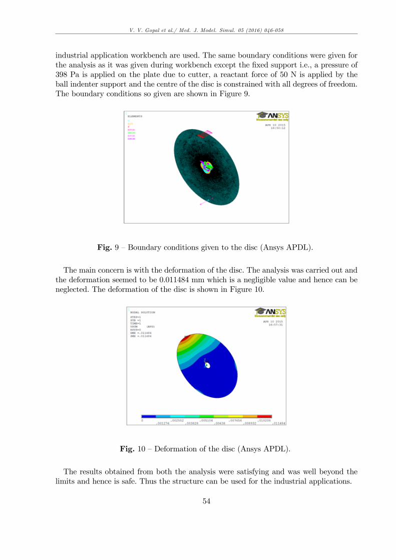
industrial application workbench are used. The same boundary conditions were given forthe analysis as it was given during workbench except the �xed support i.e., a pressure of398 Pa is applied on the plate due to cutter, a reactant force of 50 N is applied by theball indenter support and the centre of the disc is constrained with all degrees of freedom.The boundary conditions so given are shown in Figure 9.
Fig. 9 �Boundary conditions given to the disc (Ansys APDL).
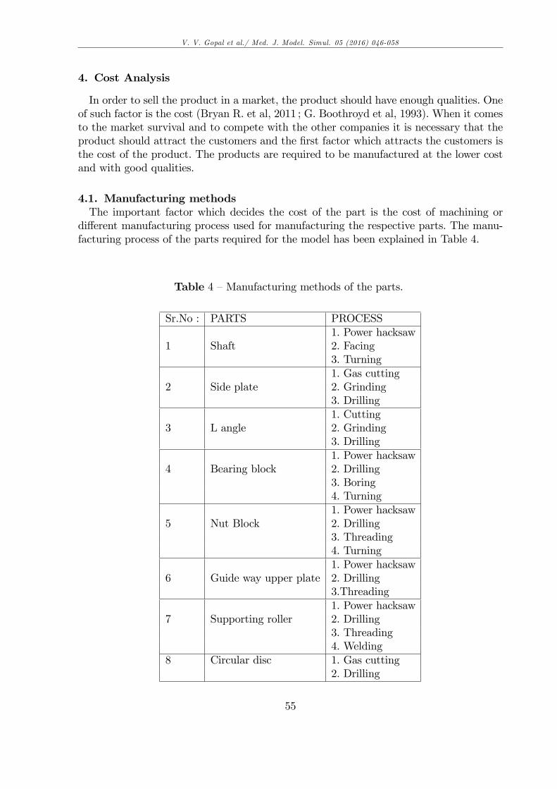
The main concern is with the deformation of the disc. The analysis was carried out andthe deformation seemed to be 0.011484 mm which is a negligible value and hence can beneglected. The deformation of the disc is shown in Figure 10.
Fig. 10 �Deformation of the disc (Ansys APDL).
The results obtained from both the analysis were satisfying and was well beyond thelimits and hence is safe. Thus the structure can be used for the industrial applications.
54
V. V. Gopal et al./ Med. J. Model. Simul. 05 (2016) 046-058
4. Cost Analysis
In order to sell the product in a market, the product should have enough qualities. Oneof such factor is the cost (Bryan R. et al, 2011 ; G. Boothroyd et al, 1993). When it comesto the market survival and to compete with the other companies it is necessary that theproduct should attract the customers and the �rst factor which attracts the customers isthe cost of the product. The products are required to be manufactured at the lower costand with good qualities.
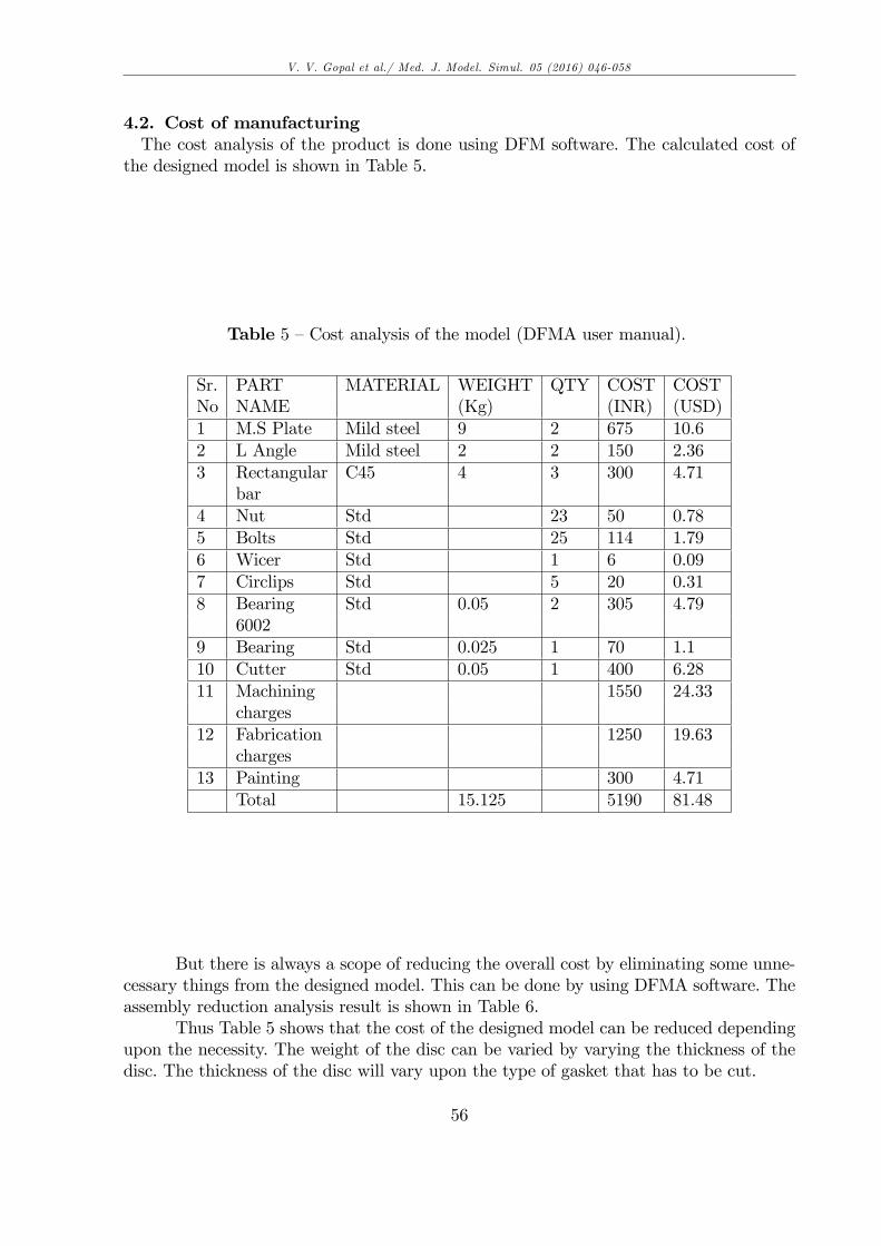
4.1. Manufacturing methodsThe important factor which decides the cost of the part is the cost of machining or
di¤erent manufacturing process used for manufacturing the respective parts. The manu-facturing process of the parts required for the model has been explained in Table 4.
Table 4 �Manufacturing methods of the parts.
Sr.No : PARTS PROCESS1. Power hacksaw
1 Shaft 2. Facing3. Turning1. Gas cutting
2 Side plate 2. Grinding3. Drilling1. Cutting
3 L angle 2. Grinding3. Drilling1. Power hacksaw
4 Bearing block 2. Drilling3. Boring4. Turning1. Power hacksaw
5 Nut Block 2. Drilling3. Threading4. Turning1. Power hacksaw
6 Guide way upper plate 2. Drilling3.Threading1. Power hacksaw
7 Supporting roller 2. Drilling3. Threading4. Welding
8 Circular disc 1. Gas cutting2. Drilling
55
V. V. Gopal et al./ Med. J. Model. Simul. 05 (2016) 046-058
4.2. Cost of manufacturingThe cost analysis of the product is done using DFM software. The calculated cost of
the designed model is shown in Table 5.
Table 5 �Cost analysis of the model (DFMA user manual).
Sr. PART MATERIAL WEIGHT QTY COST COSTNo NAME (Kg) (INR) (USD)1 M.S Plate Mild steel 9 2 675 10.62 L Angle Mild steel 2 2 150 2.363 Rectangular C45 4 3 300 4.71
bar4 Nut Std 23 50 0.785 Bolts Std 25 114 1.796 Wicer Std 1 6 0.097 Circlips Std 5 20 0.318 Bearing Std 0.05 2 305 4.79
60029 Bearing Std 0.025 1 70 1.110 Cutter Std 0.05 1 400 6.2811 Machining 1550 24.33
charges12 Fabrication 1250 19.63
charges13 Painting 300 4.71
Total 15.125 5190 81.48
But there is always a scope of reducing the overall cost by eliminating some unne-cessary things from the designed model. This can be done by using DFMA software. Theassembly reduction analysis result is shown in Table 6.
Thus Table 5 shows that the cost of the designed model can be reduced dependingupon the necessity. The weight of the disc can be varied by varying the thickness of thedisc. The thickness of the disc will vary upon the type of gasket that has to be cut.
56
V. V. Gopal et al./ Med. J. Model. Simul. 05 (2016) 046-058
Table 6 �Cost reduction analysis of the assembly (DFMA user manual).
PART WEIGHT QTY. COST WEIGHT COSTNAME REDUCTION REDUCTION
POSSIBLE POSSIBLERectangular 4 3 300 2 150barCutter 0.05 1 400 300Machining 1550 800chargesFabrication 1250 300chargesDisc 4 1 320 3 230materialTOTAL 15.125 5190 5 Kg 1780 INR
(27.95 USD)
PRODUCT 15.125 - 5 kg 7.7 kgWEIGHTPRODUCT COST 5190 �1780 3410/- INR
(53.54 USD)
5. Conclusion
As discussed above, the design is fully safe and can be used in the best possible way.Now the industries can create the gasket at the own places without going for other dealers.The designed concluded that the main di¤erence between the existing and the new designmodel is that the design complexity is reduced so that one can assemble it easily (G.Boothroyd, 2010), the weight of the model is been reduced so thus light in weight andthe last but not the least the cost of the product is been reduced to a greater extent. Thedesign can be used manually, semi-automatic or fully automated.The designed model proves to be much more superior to the existing gasket cutting
machine. And by using this system will surely will reduce the dependency of the industryon other gasket producing dealers. The result during the analysis of the project was goodwhich indicate that the product is ready for its application
REFERENCES
[1] Angrisani, L., Daponte, P., Liguori, C., Pietrosanto, A. 1999. An image-based measu-rement system for the characterization of automotive gaskets. Measurement, Vol.25,No.3, pp.169-181.
[2] Trelleborg sealing solution. 2011. Trelleborg�s �at gaskets ful�l a range of di¤erentequirements. Sealing Technology, Vol. 2011, No. 5, pp.2.
[3] David A. Nash, Y. Charles Lu, Michael E. Anderson. 2009. Finite element modelling of
57

V. V. Gopal et al./ Med. J. Model. Simul. 05 (2016) 046-058
elastomeric sealing components for cylinder-head cover noise and vibration prediction.International Journal of vehicle design, Vol. 49, No.4, pp. 287-302
[4] Dennis R. Moss, Michael M. Basic. 2012. Pressure Vessel Design Manual. 4th Edition,Butterworth-Heinemann publication.
[5] James Walker Moor�ex, 2005. �Gasket technology guide�, Understanding gaskets &dimensional guidebook, James Walker Moor�ex Limited.
[6] M.F.Spotts, T.E.Shoup, 2011. Design of Machine Elements., Dorling Kindersley (In-dia) Pvt .Ltd, 8th Edition, Licensees of Pearson Education.
[7] Catia V5, user manual.[8] Ansys workbench 14.5, Ansys APDL 14.5, user manual.[9] Koji Teramoto, Masahiko Anasoto, and Kazuaki Iwata. 1998. Coordinative Generation
of Machining and Fixturing Plans by a Modularized Problem Solver. CIRP Annuals,Manufacturing Technology, Vol.47, pp. 437�440.
[10]Edgar R. Rodriguez Ramirez. 2012. The role of surprise on persuasion in industrialdesign. International Journal of Product Development, Vol.16, No.3/4, pp. 263 - 283.
[11]Bryan R. Fischer. 2011.GD&T Update Guide : ASME Y14.5-2009. Changes, Impro-vements, and Clari�cations, Amer Society of Mechanical, Spi edition.
[12]G. Boothroyd and W. Knight. 1993. Manufacturing À La Carte : E¢ ciency : Designfor assembly. IEEE Spectrum, pp.51-53
[13]DFMA, user manual.[14]Geo¤rey Boothroyd, Peter Dewhurst, Winston A. Knight, December 8, 2010. Third
Edition. Product Design for Manufacture and Assembly. CRC Press Pages - 497 B/WIllustrations.
58


![Untitled-2 [shineupvcwindows.com]shineupvcwindows.com/catalogue/brochure.pdf · 2017. 5. 27. · CUTTING MACHINE LOCK HOLE MACHINE V - CUTTING MACHINE ... CNC - CORNER CLEANING MACHINE](https://static.fdocuments.in/doc/165x107/604763e0d38e997fae49d324/untitled-2-2017-5-27-cutting-machine-lock-hole-machine-v-cutting-machine.jpg)


