Design and Analysis of CFD Experiments for the Development ...
17
Research Article Design and Analysis of CFD Experiments for the Development of Bulk-Flow Model for Staggered Labyrinth Seal Filippo Cangioli , 1 Paolo Pennacchi , 1 Leonardo Nettis, 2 and Lorenzo Ciuchicchi 3 1 Politecnico di Milano, Via Giuseppe La Masa 1, Milan, Italy 2 Baker Hughes, a GE company, Via Felice Matteucci 2, Florence, Italy 3 Baker Hughes, a GE company, 480 All´ ee Gustave Eiffel, Le Creusot, France Correspondence should be addressed to Filippo Cangioli; fi[email protected] Received 22 December 2017; Accepted 29 March 2018; Published 15 May 2018 Academic Editor: Tariq Iqbal Copyright © 2018 Filippo Cangioli et al. is is an open access article distributed under the Creative Commons Attribution License, which permits unrestricted use, distribution, and reproduction in any medium, provided the original work is properly cited. Nowadays, bulk-flow models are the most time-efficient approaches to estimate the rotor dynamic coefficients of labyrinth seals. Dealing with the one-control volume bulk-flow model developed by Iwatsubo and improved by Childs, the “leakage correlation” allows the leakage mass-flow rate to be estimated, which directly affects the calculation of the rotor dynamic coefficients. is paper aims at filling the lack of the numerical modelling for staggered labyrinth seals: a one-control volume bulk-flow model has been developed and, furthermore, a new leakage correlation has been defined using CFD analysis. Design and analysis of computer experiments have been performed to investigate the leakage mass-flow rate, static pressure, circumferential velocity, and temperature distribution along the seal cavities. Four design factors have been chosen, which are the geometry, pressure drop, inlet preswirl, and rotor peripheral speed. Finally, dynamic forces, estimated by the bulk-flow model, are compared with experimental measurements available in the literature. 1. Introduction Labyrinth seals and their sealing principles are commonplace in turbomachinery and they can arise in various configura- tions [1]. e most popular are the straight-through, the stag- gered, the slanted, and the stepped labyrinth seals. By their nature, labyrinth seals are noncontact seals that can harmfully rub against stationary parts [2]. eir working principle consists in reducing the leakage mass-flow rate by dissipating the flow kinetic energy via sequential cavities arranged to impose a tortuous path to the fluid (see the scheme of a staggered labyrinth seal in Figure 1). e speed and pressure at which they operate are bounded by their structural design. e clearance is defined by aerothermomechanical condi- tions that stave off the contact against the shroud under radial and axial excursions. In straight-through labyrinth seal, the angle at which the flow approaches to the teeth is usually 90 ∘ ; the coefficients of discharge ( ), peculiar of labyrinth seals, emphasize the effectiveness of the sealing element. e discharge coefficient is defined as the ratio between the actual mass-flow rate and that in ideal flow conditions. e relation between the sharpness of the tooth and the ability to restrict the flow has been given by Mahler [3] and more recently explored by means of computational fluid dynamics (CFD) in [4]. Labyrinth seals are effective in reducing the flow but have a strong effect on the dynamic behaviour and oſten lead to dynamic instabilities. ese problems have been addressed by several researchers starting with omas [5] and Alford [6]. ey recognized that dynamic forces can lead to instabilities. Childs [7] addressed the root cause to the swirl velocity and introduced the swirl brake at the seal inlet to mitigate the circumferential velocity of the fluid. e current trends in the oil and gas market lead the manufacturers to maximize the turbomachinery efficiency. is target pushes the rotor dynamic design to be challeng- ing. erefore, the accuracy of rotor dynamic analyses has become of primary importance to avoid undesired instability phenomenon. Because labyrinth seals are one of the major sources of destabilizing effects, it is straightforward that the accurate prediction of labyrinth seal dynamic coefficients is crucial. e bulk-flow model is the most used approach for estimating the seal dynamic coefficients thanks to the low Hindawi International Journal of Rotating Machinery Volume 2018, Article ID 9357249, 16 pages https://doi.org/10.1155/2018/9357249
Transcript of Design and Analysis of CFD Experiments for the Development ...

Research ArticleDesign and Analysis of CFD Experiments for the Development ofBulk-Flow Model for Staggered Labyrinth Seal
Filippo Cangioli ,1 Paolo Pennacchi ,1 Leonardo Nettis,2 and Lorenzo Ciuchicchi3
1Politecnico di Milano, Via Giuseppe La Masa 1, Milan, Italy2Baker Hughes, a GE company, Via Felice Matteucci 2, Florence, Italy3Baker Hughes, a GE company, 480 Allee Gustave Eiffel, Le Creusot, France
Correspondence should be addressed to Filippo Cangioli; [email protected]
Received 22 December 2017; Accepted 29 March 2018; Published 15 May 2018
Academic Editor: Tariq Iqbal
Copyright © 2018 FilippoCangioli et al.This is an open access article distributed under the Creative CommonsAttribution License,which permits unrestricted use, distribution, and reproduction in any medium, provided the original work is properly cited.
Nowadays, bulk-flow models are the most time-efficient approaches to estimate the rotor dynamic coefficients of labyrinth seals.Dealing with the one-control volume bulk-flow model developed by Iwatsubo and improved by Childs, the “leakage correlation”allows the leakage mass-flow rate to be estimated, which directly affects the calculation of the rotor dynamic coefficients. Thispaper aims at filling the lack of the numerical modelling for staggered labyrinth seals: a one-control volume bulk-flow modelhas been developed and, furthermore, a new leakage correlation has been defined using CFD analysis. Design and analysis ofcomputer experiments have been performed to investigate the leakage mass-flow rate, static pressure, circumferential velocity, andtemperature distribution along the seal cavities. Four design factors have been chosen, which are the geometry, pressure drop, inletpreswirl, and rotor peripheral speed. Finally, dynamic forces, estimated by the bulk-flow model, are compared with experimentalmeasurements available in the literature.
1. Introduction
Labyrinth seals and their sealing principles are commonplacein turbomachinery and they can arise in various configura-tions [1].Themost popular are the straight-through, the stag-gered, the slanted, and the stepped labyrinth seals. By theirnature, labyrinth seals are noncontact seals that can harmfullyrub against stationary parts [2]. Their working principleconsists in reducing the leakage mass-flow rate by dissipatingthe flow kinetic energy via sequential cavities arranged toimpose a tortuous path to the fluid (see the scheme of astaggered labyrinth seal in Figure 1). The speed and pressureat which they operate are bounded by their structural design.
The clearance is defined by aerothermomechanical condi-tions that stave off the contact against the shroud under radialand axial excursions. In straight-through labyrinth seal, theangle at which the flow approaches to the teeth is usually90∘; the coefficients of discharge (𝐶𝑓), peculiar of labyrinthseals, emphasize the effectiveness of the sealing element. Thedischarge coefficient is defined as the ratio between the actualmass-flow rate and that in ideal flow conditions. The relationbetween the sharpness of the tooth and the ability to restrict
the flow has been given by Mahler [3] and more recentlyexplored by means of computational fluid dynamics (CFD)in [4].
Labyrinth seals are effective in reducing the flow but havea strong effect on the dynamic behaviour and often lead todynamic instabilities.These problems have been addressed byseveral researchers starting with Thomas [5] and Alford [6].They recognized that dynamic forces can lead to instabilities.Childs [7] addressed the root cause to the swirl velocity andintroduced the swirl brake at the seal inlet to mitigate thecircumferential velocity of the fluid.
The current trends in the oil and gas market lead themanufacturers to maximize the turbomachinery efficiency.This target pushes the rotor dynamic design to be challeng-ing. Therefore, the accuracy of rotor dynamic analyses hasbecome of primary importance to avoid undesired instabilityphenomenon. Because labyrinth seals are one of the majorsources of destabilizing effects, it is straightforward that theaccurate prediction of labyrinth seal dynamic coefficients iscrucial.
The bulk-flow model is the most used approach forestimating the seal dynamic coefficients thanks to the low
HindawiInternational Journal of Rotating MachineryVolume 2018, Article ID 9357249, 16 pageshttps://doi.org/10.1155/2018/9357249

2 International Journal of Rotating Machinery
Figure 1: Schematic view of a staggered labyrinth seal.
computational effort compared to CFD calculations. It wasdeveloped by Iwatsubo [8] and improved by Childs andScharrer [9] in the 80s. The bulk-flow model is a con-trol volume approach: the continuity and circumferentialmomentum equations are solved for each cavity, allowingthe circumferential fluid dynamics within the seal to beinvestigated. For the axial fluid dynamics, empirical corre-lations are required, aiming at estimating the leakage andthe pressure distribution. No turbulence model is employedin the bulk-flow model; therefore also the effect of theturbulence is demanded to correlations that estimate the wallshear stresses.The leakage strictly influences the swirl velocityprofile along the seal and consequently the resulting dynamiccoefficients.
Dealing with staggered labyrinth seals, few models allowthe dynamic coefficients to be estimated, despite the factthat this seal configuration is widely used in turbomachinery,especially in steam turbines. The advantage of this configu-ration, with respect to straight-through labyrinth seal, is thereduction of the leakagemass-flow rate given equal clearance.
Wang et al. [10] use the straight-through bulk-flowmodelfor the staggered labyrinth seal; Childs [7] considered thekinetic energy carry-over equal to the unity for all thecavities. Kwanka and Ortinger [11] compared the numericalresults of the bulk-flow theory with experimental resultsperformed on a staggered labyrinth seal. They revealed thestrong connection between the circumferential flow and theaxial one. The numerical results were not accurate comparedto the experimental ones. The leakage correlation used byKwanka et al. did not reproduce well the “zig-zag” behaviourof the discharge coefficients, because they considered anaverage value. Li et al. [12] investigated numerically andexperimentally the effects of the pressure ratio and rotationalspeed on the leakage flow in a staggered labyrinth seal. Intheir paper, the authors do not report any correlation for theprediction of the leakage flow.
This paper aims at filling the lack of analytical modelsfor staggered labyrinth seals. Firstly, the authors performed adesign and analysis of computer experiments (DACE) usingsteady-state CFD analysis to develop a new empirical correla-tion for the prediction of staggered labyrinth seal leakage.TheCFD analysis investigates several seal geometries and variousoperating conditions, which are pressure drop, inlet preswirl,and rotor peripheral speed. To capture the nonlinear depen-dency of these factors on the flow conditions, three levelseach are chosen, except two for the preswirl. The correlationobtained is finally verified numerically, comparing the results
P0i−1 P0i
mi
V0i−1 V0i
ℎ0i−1ℎ0i
Ri R
mi+1
Ri+1
STATOR
ROTOR
P0i+1
V0i+1
ℎ0i+1
Figure 2: Bulk-flow control volumes.
of the bulk-flow model with those of a CFD analysis in termsof leakage mass-flow rate, pressure distributions, and Machnumber.
In conclusion, the rotor dynamic coefficients predictionhas been compared with the experimental measurementsperformed by Kwanka and Ortinger [11], highlighting themore accurate estimation of the cross-force with respect toother bulk-flow models.
2. Bulk-Flow Steady-State Solution
The estimation of the steady leakage, pressure, and circum-ferential velocity distribution represents the so-called zeroth-order solution in the bulk-flow model, as described in [13].For a fixed pressure drop and assuming, at a first stage, anisenthalpic process, the leakage and the pressure distributionin the seal cavities are determined by solving iteratively thecontinuity equation, until the mass-flow rate is equal foreach control volume (see Figure 2). Then, the enthalpy andthe circumferential velocity in each cavity are determinedby solving the coupled circumferential momentum andenergy equation. Multivariate Newton-Raphson algorithmis employed to find the solution. At the following step, theleakage is calculated onemore time, considering the enthalpyvariation previously estimated. The iteration continues untilthe leakage mass flow-rate converges.
The continuity, circumferential momentum, and energyzeroth-order equations for each cavity are stated as follows:
Continuity Equation
��01 ≡ ⋅ ⋅ ⋅ ≡ ��0𝑖 ≡ ⋅ ⋅ ⋅ ≡ ��0𝑁𝑇 ≡ ��0. (1)
Circumferential Momentum Equation
��0 (𝑉0𝑖 − 𝑉0𝑖−1) = 𝜏0𝑟𝑖𝑎𝑟𝑖 − 𝜏0𝑠𝑖𝑎𝑠𝑖. (2)
Energy Equation
��0 (ℎ0𝑖 + 𝑉0𝑖22 ) − ��0 (ℎ0𝑖−1 + 𝑉0𝑖−122 ) = 𝜏0𝑟𝑖𝑎𝑟𝑖𝑅𝑠Ω, (3)
where ��0 is the steady leakage mass-flow rate, 𝑉0𝑖 and ℎ0𝑖 arethe steady circumferential velocity and enthalpy for the 𝑖thcavity. 𝜏0𝑟𝑖 and 𝜏0𝑠𝑖 are the shear stresses on the rotor and statorparts, whereas 𝑎𝑟𝑖 and 𝑎𝑠𝑖 are the lengths of the rotor and statorparts, respectively.

International Journal of Rotating Machinery 3
Figure 3: Staggered seal geometry.
The leakage correlation (��𝑖) used in themodel is given bythe Neumann formula, as described in [14]:
��𝑖 = 𝑅𝑠𝑖𝑅𝑠 𝐶𝑓𝑖𝜇𝑖𝐻𝑖√𝜌𝑖−1 (𝑃𝑖−1 − 𝑃𝑖), (4)
where 𝐶𝑓𝑖 and 𝜇𝑖 are, respectively, the discharge coefficientand kinetic energy carry-over coefficient,𝐻𝑖 is the clearance,and 𝑃𝑖 and 𝜌𝑖 are the pressure and density in the 𝑖th cavity.
The shear stresses both on the rotor and on the stator(𝜏0𝑟𝑖 and 𝜏0𝑠𝑖) have been evaluated by implementing theSwamee-Jain [15] explicit formula for the estimation of theDarcy friction factor. Compared with the Blasius correlation,which is used in several models [9, 16–19], the Swamee-Jaincorrelation is more accurate in the calculation of the frictionfactor, because it takes into account the roughness of thesurface and it is validated also for high Reynolds numbers.A comprehensive investigation of the correlation has beenperformed by Kiijarvi in [20]. The rotor and stator frictionfactors are defined as
𝑓𝑟𝑖 = 116 [log10 ( 𝑒𝑟3.7 ⋅ 𝐷ℎ𝑖 +5.74Re𝑟𝑖0.9
)]−2
𝑓𝑠𝑖 = 116 [log10 ( 𝑒𝑠3.7 ⋅ 𝐷ℎ𝑖 +5.74Re𝑠𝑖0.9
)]−2 ,(5)
where 𝐷ℎ𝑖 is the circumferential hydraulic diameter, 𝜇𝑖 isthe kinematic viscosity, 𝑒 is the absolute roughness of therotor/stator surface, andΩ is the rotational speed of the rotor.The Reynolds numbers are defined for the rotor and statorparts, respectively, as follows:
Re𝑟𝑖 = 𝐷ℎ𝑖𝑉𝑅𝑖𝜇𝑖Re𝑠𝑖 = 𝐷ℎ𝑖𝑉𝑆𝑖𝜇𝑖 . (6)
The shear stresses generated by the fluid/structure inter-action are evaluated considering both the axial and circum-ferential velocity, as described in [19] by Wyssmann et al., asfollows:
𝜏𝑟𝑖 = 𝜌𝑖2 𝑓𝑟𝑖 (𝑅𝑠Ω − 𝑉𝑖) 𝑉𝑅𝑖 𝑉𝑅𝑖 = √𝑈𝑖2 + (𝑅𝑠Ω − 𝑉𝑖)2𝜏𝑠𝑖 = 𝜌𝑖2 𝑓𝑟𝑖𝑉𝑖𝑉𝑆𝑖 𝑉𝑆𝑖 = √𝑈𝑖2 + 𝑉𝑖2,
(7)
where 𝑈𝑖 is the axial velocity of the fluid in the 𝑖th cavity,which is estimated as a function of the calculated mass-flowrate as
𝑈𝑖 = ��𝑖𝐶𝑓𝑖𝐻𝑖𝜌𝑖 . (8)
3. Preliminary Results
To investigate the accuracy of the leakage correlation usedfor straight-through labyrinth seals in the case of staggered
Flow
P
S
S
R
T
F
H
G
Figure 4: Parametric view of staggered labyrinth seal.
Table 1: Seal geometry parameter.
Seal geometryShaft radius 𝑅𝑠 189Radial clearance (mm) 𝑠 0.6Steps-to-casing radial distance (mm) 𝐺 2.00Steps height (mm)𝐻 2.00Steps width (mm) 𝐹 3.00𝐽-strips width at tip (mm)𝑊 0.25𝐽-strips pitch (mm) 𝑃 4.00𝐽-strip-to-step axial distance (mm) 𝑇 2.75𝐽-strips number𝑁𝐽 47Rotor steps number𝑁𝑆 24
seals, the zeroth-order solutions are compared with the CFDresults. Steady-state CFD analysis is very accurate in theprediction of the leakage, static pressure, and circumferentialvelocity within the seal; therefore CFD has been consideredas the reference for the zeroth-order solution.
A detailed description of the CFD analysis is shown inthe next chapter of the paper. The seal geometry is shownin Figure 3, and the geometrical parameters are reportedin Table 1, using the nomenclature shown in Figure 4. Theworking fluid is the steam.
The leakage can be calculated in two manners: consider-ing the kinetic energy carry-over coefficient (Wang’s model),as suggested by Wang et al. [10], or assuming that the kineticenergy carry-over coefficient is equal to the unity for all theconstrictions (Childs’ model), as suggested by Childs in [7].Both models use the empirical Neumann’s correlation (see(4)) for the leakage [14] and Chaplygin’s formula (see (9))for the discharge coefficient. The kinetic energy carry-overcoefficient is calculated using the semiempirical correlationdeveloped by Hodkinson in [21].
𝐶𝑓𝑖 = 𝜋𝜋 + 2 − 5 ⋅ 𝛽𝑖 + 2 ⋅ 𝛽2𝑖where, 𝛽𝑖 = (𝑃𝑖−1𝑃𝑖 )
(𝛾−1)/𝛾 − 1(9)

4 International Journal of Rotating Machinery
0,0
0,2
0,4
0,6
0,8
1,0
1,2
1,4
1,6
1,8
2,0
Mas
s-flo
w ra
te (k
g/s)
Wang’s model Childs’ modelCFD
Figure 5: Mass-flow rate comparison.
𝜇𝑖= √ 11 − ((𝑁𝐽 − 1) /𝑁𝐽) ⋅ ((𝐻𝑖/𝐿 𝑖) / ((𝐻𝑖/𝐿 𝑖) + 0.02)) .
(10)
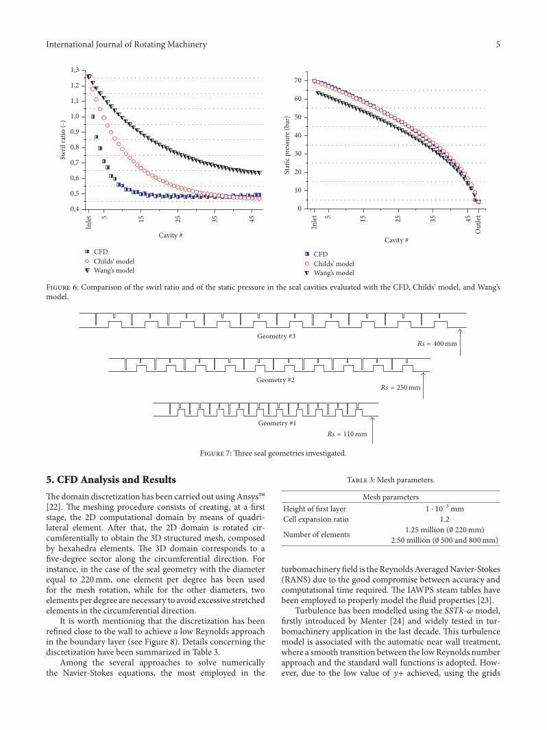
The results in terms of leakage mass-flow rate are shownin Figure 5, while the swirl velocity and the pressure dis-tribution are shown in Figure 6. The mass-flow rate isoverestimated for both bulk-flow models: the relative erroris, respectively, equal to +75% and +272% for Childs’ modeland Wang’s model. The swirl ratios along the seal cavities arestrongly influenced by the mass flow. Even if the asymptoticvalue of the swirl ratio for Childs’ model is equal to that ofthe CFD, the values in the first cavities are far from the CFDones.The predicted static pressure distribution is very similarto Childs’ model.
Eventually, Childs’ model is the more accurate one-control volumebulk-flowmodel in the literature for staggeredlabyrinth seals; however, the results in terms of leakage,pressure, and circumferential velocity distribution are notaccurate enough compared to CFD results. The zeroth-order solution strongly influences the prediction of the sealdynamic coefficients; hence, the authors decide to develop anew empirical correlation for staggered labyrinth seal.
4. Design and Analysis ofComputer Experiments
Design and analysis of CFD experiments allow severalstaggered seal geometries and operating conditions to beinvestigated for the development of a new leakage correlation.A priori, it is not possible to know which are the geometricparameters that influence the leakage flow rate, as well as theoperating conditions.
Three seal geometries are chosen according to the OEMsdesign criteria, while additional two are selected in orderto extend the domain of the investigation in the case ofpossible axial shifting of the rotor. Axial excursion of the rotorcommonly happens during the start-up condition or even
Table 2: Design of computer experiments.
Test Pressure drop Geometry Peripheral speed Preswirl(bar) (m/s) —
1 50 Geom 1 69.1 1.92 20 Geom 1 69.1 1.93 10 Geom 1 69.1 1.94 50 Geom 2 69.1 1.95 50 Geom 3 69.1 1.96 20 Geom 2 69.1 1.97 20 Geom 3 69.1 1.98 50 Geom 4 69.1 1.99 50 Geom 5 69.1 1.910 50 Geom 1 69.1 0.511 20 Geom 1 69.1 0.512 50 Geom 2 69.1 0.513 50 Geom 3 69.1 0.514 50 Geom 1 115.2 1.915 20 Geom 1 115.2 1.916 50 Geom 2 115.2 1.917 50 Geom 1 161.3 1.918 50 Geom 1 115.2 0.519 20 Geom 2 115.2 1.920 50 Geom 2 115.2 0.521 50 Geom 3 115.2 0.522 20 Geom 2 69,1 0,523 20 Geom 3 69.1 0.524 20 Geom 1 115.2 0.525 50 Geom 4 161.3 1.926 50 Geom 5 161.3 1.927 10 Geom 4 69.1 1.928 10 Geom 5 69.1 1.929 50 Geom 4 69.1 0.530 50 Geom 5 69.1 0.531 50 Geom 1 161.3 0.532 10 Geom 1 69.1 0.533 10 Geom 1 161.3 1.9
during the variation of the process parameters (i.e., the outputpower density). The validation of the correlation also foroff-design seal operations allows extending the seal dynamiccoefficients predictability. The geometric parameters thatdefine the seal geometry are those reported in Table 1. Threedifferent rotor diameters have been investigated (220mm,500mm, and 800mm); the teeth are 20, while the rotor stepsare 10. The additional two seal geometries are equal to thosewith the rotor diameter equal to 500mm (geometry #4) and800mm (geometry #5) but with a different length of the rotorstep. The three main geometries are shown in Figure 7; thesteam flows from right to left.
Because CFD analysis is very time-consuming, a factorialDACE is performed, even if not all the combinations ofthe parameters have been investigated. The list of the CFDanalysis performed is shown in Table 2.
International Journal of Rotating Machinery 5
CFDChilds’ modelWang’s model
CFDChilds’ modelWang’s model
0,4
0,5
0,6
0,7
0,8
0,9
1,0
1,1
1,2
1,3Sw
ril ra
tio (-
)
5 15 25 35 45O
utle
t
Inle
t
Cavity #
5 15 453525
Inle
t
Cavity #
0
10
20
30
40
50
60
70
Stat
ic p
ress
ure (
bar)
Figure 6: Comparison of the swirl ratio and of the static pressure in the seal cavities evaluated with the CFD, Childs’ model, and Wang’smodel.
Geometry #3
Geometry #2
Geometry #1Rs = 110 mm
Rs = 250 mm
Rs = 400 mm
Figure 7: Three seal geometries investigated.
5. CFD Analysis and Results
Thedomain discretization has been carried out using Ansys�[22]. The meshing procedure consists of creating, at a firststage, the 2D computational domain by means of quadri-lateral element. After that, the 2D domain is rotated cir-cumferentially to obtain the 3D structured mesh, composedby hexahedra elements. The 3D domain corresponds to afive-degree sector along the circumferential direction. Forinstance, in the case of the seal geometry with the diameterequal to 220mm, one element per degree has been usedfor the mesh rotation, while for the other diameters, twoelements per degree are necessary to avoid excessive stretchedelements in the circumferential direction.
It is worth mentioning that the discretization has beenrefined close to the wall to achieve a low Reynolds approachin the boundary layer (see Figure 8). Details concerning thediscretization have been summarized in Table 3.
Among the several approaches to solve numericallythe Navier-Stokes equations, the most employed in the
Table 3: Mesh parameters.
Mesh parametersHeight of first layer 1 ⋅ 10−3mmCell expansion ratio 1.2Number of elements 1.25million (0 220mm)2.50million (0 500 and 800mm)
turbomachinery field is the ReynoldsAveragedNavier-Stokes(RANS) due to the good compromise between accuracy andcomputational time required. The IAWPS steam tables havebeen employed to properly model the fluid properties [23].
Turbulence has been modelled using the 𝑆𝑆𝑇𝑘-𝜔 model,firstly introduced by Menter [24] and widely tested in tur-bomachinery application in the last decade. This turbulencemodel is associated with the automatic near wall treatment,where a smooth transition between the lowReynolds numberapproach and the standard wall functions is adopted. How-ever, due to the low value of 𝑦+ achieved, using the grids

6 International Journal of Rotating Machinery
0 0.001 0.002 (m)
0.00150.0005
Z
Y
X
Figure 8: Details of the labyrinth seal discretization.
Inlet: Total Pressure Stator: No slip wall
Outlet: Static Pressure
Rotating PeriodicityRotor: No slip wall
Velocity components
Rotating
Figure 9: Boundary conditions scheme.
employed in this paper, this treatment corresponds to the lowReynolds model; hence, the viscous sublayer is not modelledbut directly solved. This approach is surely preferable dueto the final purpose of the present analysis, where the exactamount of flow rate for a given pressure dropmust be assessedthrough the clearances.
The boundary condition scheme is hereafter introducedin Figure 9. The same set of conditions are imposed to all thetest cases. The value of inlet total pressure is changed at eachnew iteration to target the desired pressure drop; moreover,the circumferential velocity component is adjusted to obtainthe desired preswirl ratio.
The results of some simulations are shown in Figures 10and 11. Static pressure and temperature contours are reportedin Figure 10. Dimensionless values are obtained using thedownstream value equaling the unity. Furthermore, stream-lines in the meridional plane are illustrated in Figure 11,focusing on the inlet and outlet locations. The flow structurebefore the first clearance is different from the one occurringupstream the consecutive teeth.
6. Discharge Coefficients Correlation
The objective of the paper is the development of a newleakage correlation to accurately predict the leakage mass-flow rate and the pressure distribution in the seal cavities insteady-state condition (centred rotor). In a nozzle or otherconstrictions, the discharge coefficient is defined as the ratioof the actual mass-flow rate at the discharge end of theconstriction to that in which an ideal working fluid expandswith the same initial and exit conditions. Starting from thedefinition of the discharge coefficient, it is possible to definethe leakage formula, which is equal to the product betweenthe discharge coefficient and the ideal mass-flow rate. Theideal mass-flow rate in a constriction is derived from theBernoulli equation [25], assuming that the outlet area ismuchsmaller than the inlet one. The coefficient of discharge isdefined as
𝐶𝑓𝑖 = ��𝑖+1𝐴 𝑖√2𝜌𝑖 (𝑃0𝑖−1 − 𝑃0𝑖) . (11)

International Journal of Rotating Machinery 7
0.00
e+00
0
7.38
e−00
2
1.77
e−00
1
2.80
e−00
1
3.83
e−00
1
4.86
e−00
1
5.89
e−00
1
6.92
e−00
1
7.95
e−00
1
8.98
e−00
1
1.00
e+00
0
Dimensionless static pressure
Z
Y
X
(a)
0.00
e+00
0
1.90
e−00
2
1.28
e−00
1
2.37
e−00
1
3.46
e−00
1
4.55
e−00
1
5.64
e−00
1
6.73
e−00
1
7.82
e−00
1
8.91
e−00
1
1.00
e+00
0
Dimensionless static temperature
Z
Y
X
(b)
Figure 10: Nondimensional static pressure (a) and temperature (b) contours.
0.00
0e+00
0
1.00
0e+00
0
Dimensionless axial velocity -streamlin
Z
Y
X
2.49
7e−00
1
4.99
5e−00
1
7.49
2e−00
1
(a)
0.00
0e+00
0
Dimensionless axial velocity -streamline
2.49
7e−00
1
4.99
5e−00
1
7.49
2e−00
1
1.00
0e+00
0
Z
Y
X
(b)
Figure 11: Meridional velocity coloured streamlines at inlet (a) and outlet (b) location.

8 International Journal of Rotating Machinery
0
0.2
0.4
0.6
0.8
1
Disc
harg
e coe
ffici
ent [
-]
2 3 4 5 6 7 8 9
Last
Toot
h
Firs
t Too
th 12 13 14 15 16 17 18 1910 11
Orifice #
Figure 12: Discharge coefficients in the seal orifice for the testnumber 4 (seal diameter = 500mm, pressure drop = 50 bar, inletpreswirl = 1.9, and rotor peripheral velocity = 66.19m/s).
Since the mass-flow rate, pressure, and density can beevaluated by the CFD, the discharge coefficient for eachcavity can be evaluated. Using the CFD data of all the testsinvestigated by the DACE, the idea is to develop a newcorrelation based on the geometric parameters and on theoperating conditions.
The authors have observed that the discharge coefficientshave different values depending on the constriction type(long teeth or short teeth coupled with the rotor step);however, the values along the seal orifices almost remainconstant, for both the constriction types, expect for the firsttooth (see Figure 12). Since the discharge coefficient dependson the angle at which the fluid approaches to the tooth,the different discharge coefficient is likely due to the fluid,which approaches to the long teeth and to the short ones intwo different manners. For instance, as can be observed inFigure 12, for test 1 shown in Table 2, the discharge coefficientin correspondence of the short teeth is about 0.3, whereas forlong teeth it is practically constant and equal to 0.48. For thefirst tooth, the discharge coefficient is about 0.6.
After several investigations, the authors have observedthat two geometrical parameters mainly influence the dis-charge coefficient. These parameters are listed in Table 4.The parameter 𝑠/(𝐻 + 𝐺) is related to the ratio between theheight of the constriction and the height of the seal. Theother parameters are related to the axial position and lengthof the rotor step. In addition, one parameter regarding theoperating conditions has been considered. From a primaryscreening of the CFD results, the authors observed that theonly operating condition parameter that significantly affectsthe leakage is the pressure drop. The inlet preswirl and therotor peripherical speed have practically no influence on themass flow and therefore on the pressure distribution.
The authors assume that the cross-dependence termsbetween the geometrical parameters and operating condi-tions are negligible. Thus, at a first stage, the dischargecoefficients have been fitted with a polynomial as a functionof the geometrical parameters for both the 𝑗-strips teeth andthe short 𝑗-strips teeth combined with the rotor steps. At a
0,20
Disc
harg
e coe
ffici
ent
0,20
0,18
0,16
0,14
0,12
0,3
0,2
0,1
0,25
0,30
0,35
0,40
0,45
0,50
0,55
0,60
xs ys
Figure 13: Surface fitting of the discharge coefficients for the shortteeth with the geometrical parameters.
Table 4: Nomenclature of the geometric parameters defined inTable 1.Geometric parametersfor the 𝑗-strip Geometric parameters for
the rotor step
𝑥𝑗 = 𝑠𝐻 + 𝐺 𝑥𝑠 = 𝑠𝐻 + 𝐺𝑦𝑗 = 1 − 𝐹 + 𝑇 − 𝑃𝑃 −𝑊 𝑦𝑠 = 1 − 𝑇𝑃 −𝑊second stage, the residual between the discharge coefficientsevaluated using the CFD data and the discharge coefficientscalculated with the polynomial in (12)-(13) have been fittedusing the operating parameter as shown in (14)-(15). Thesuperscripts and subscripts “𝑗” indicate the long 𝑗-strips (longteeth), whereas the superscripts and subscripts “s” indicatethe short j-strips combined with the rotor steps.
𝐶(𝑗)𝑓
= 𝑞0 + 𝑞1𝑥𝑗 + 𝑞2𝑦𝑗 + 𝑞3𝑥𝑗2 + 𝑞4𝑥𝑗𝑦𝑗 (12)
𝐶(𝑠)𝑓 = 𝑝0 + 𝑝1𝑥𝑠 + 𝑝2𝑦𝑠 + 𝑝3𝑥𝑠2 + 𝑝4𝑥𝑠𝑦𝑠 (13)
Residual(𝑗) = 𝑞5 + 𝑞6√𝜌in (𝑃in − 𝑃out) (14)
Residual(𝑠) = 𝑝5 + 𝑝6√𝜌in (𝑃in − 𝑃out) . (15)
For confidentiality reasons, the values of the coefficients𝑞0, . . . , 𝑞6 and 𝑝0, . . . , 𝑝6, shown in (12)–(15), are not reportedin the paper.
Figures 13 and 14 show the polynomial surface that fitsthe discharge coefficients evaluated with the CFD analysisfor both short teeth (Figure 13) and long teeth (Figure 14).The blue points represent the average value of the dischargecoefficients, in correspondence of the rotor step, for eachCFDanalysis. The CFD points are well fitted, since the adjusted 𝑅2

International Journal of Rotating Machinery 9
0,7
0,6
0,120,14
0,160,18
0,20
0,0
0,5
1,0
1,5
yj
x j
−1,5
−1,0
−0,5
Disc
harg
e coe
ffici
ent
Figure 14: Surface fitting of the discharge coefficients for the longteeth with the geometrical parameters.
2000 4000 6000 8000 10000 12000 14000−0,06
−0,04
−0,02
0,00
0,02
0,04
Resid
ual
0,06
0,08
0,10
√in(Pin − Pout)
Figure 15: Curve fitting of the residual for the short teeth with theoperating parameter.
[26] is about 0.97 for the short teeth and 0.98 for the longones, whereas the root mean square error (RMSE) [26] isequal to 0.01406 and 0.01399, respectively. These statisticalparameters highlight the goodness of fit of the data.
Furthermore, Figures 15 and 16 show the fitting of theresidual by the operating parameter (√𝜌in(𝑃in − 𝑃out)). Theblue points represent the average value of the residual, incorrespondence of the rotor step, for each CFD analysis. Theadjusted 𝑅2 is about 0.9689 and the RMSE is 0.01406.
The discharge coefficient in correspondence of the firsttooth has been considered constant for all the tests and itseems to be uncorrelated from the geometric parameters andfrom the pressure drop.
6.1. Prediction of the Leakage and Pressure Distribution. Thenew discharge coefficient correlation has been implementedin the bulk-flow model. The bulk-flow leakage mass-flow
−0,04
−0,02
0,00
0,02
0,04
0,06
0,08
Resid
ual
2000 4000 6000 8000 10000 12000 14000√in(Pin − Pout)
Figure 16: Curve fitting of the residual for the long teeth with theoperating parameter.
00
1
2
3
4
Bulk
-flow
leak
age (
kg/s
)5
6
1 2 3 4CFD Leakage (kg/s)
5 6
Figure 17: Nomenclature of the geometric parameters.
estimations compared to the CFD leakage are shown inFigure 17. The bulk-flow leakage is in the range of ±6% ofrelative error (the blue region defines the ±10% of relativeerror).
Moreover, the pressure distribution predicted with thebulk-flow model is very similar to that evaluated withthe CFD. In Figure 18(a), the pressure shows a “zig-zag”behaviour along the seal, which is due to the nonconstantdischarge coefficients (see Figure 18(b)).
6.2. Prediction of the Circumferential Velocity. In this section,the authors have compared the fluid-wall shear stressesestimated by the bulk-flowmodel with those computed usingthe CFD. For the sake of brevity, only the results related totest case 1 are reported (see Figure 19) considering both caseswith and without the axial velocity component in the bulk-flow model. The accuracy of the results is still long valid forthe other tests.

10 International Journal of Rotating Machinery
Bulk-FlowCFD
4
5
6
7
8
9St
atic
Pre
ssur
e (Pa
)×106
3 5 7 9 11 1513 17 19
Inle
t
Out
let
Cavity #
(a)
Bulk-FlowCFD
0
0.2
0.4
0.6
0.8
1
Disc
harg
e coe
ffici
ent [
-]
Last
toot
h
Firs
t too
th 6 8 10 12 14 16 182 4
Orifice #
(b)
Figure 18: Static pressure distribution in the seal cavities and discharge coefficients in the seal orifices for the test number 1 (seal diameter =220mm, pressure drop = 50 bar, inlet preswirl = 1.9, and rotor peripheral velocity = 66.19m/s).
Shear stress on rotor
w/ axial velocityw/o axial velocityCFD
w/ axial velocityw/o axial velocityCFD
Shear stress on stator
−300
−200
−100
0
100
200
300
(Pa)
−800
−600
−400
−200
0
(Pa)
0.02 0.04 0.060Axial coordinate (m)
0.02 0.04 0.060Axial coordinate (m)
Figure 19: Rotor and stator shear stresses as a function of the axial coordinate for case 1 shown in Table 2.
The CFD shear stresses are averaged along the lengthof each cavity to be compared with the bulk-flow results.In Figure 20, the circumferential velocity profile is shown.Typically, in the 1CV bulk-flow model (see bulk-flow modelsin [9, 10, 18]), the shear stresses are evaluated consideringonly the circumferential velocity, whereas the authors have
considered also the contribution of the axial velocity (see (7))as suggested in [19].
6.3. Numerical Verification of the New Correlation. The newcorrelation has been numerically verified using the resultsof the staggered seal shown in Figure 3, which has about

International Journal of Rotating Machinery 11
BF w/ axial velocityBF w/o axial velocityCFD
20
40
60
80
100
120
Circ
umfe
rent
ial V
eloci
ty (m
/s)
0.01 0.02 0.03 0.04 0.05 0.060Axial coordinate (m)
Figure 20: Circumferential velocity as a function of the axialcoordinate for case 1 shown in Table 2.
twice the teeth of the DACE seal geometries and moreoverthe operating conditions are far from those investigated inthe DACE. The relative error between the leakage evaluatedwith the bulk-flow model and the one with the CFD is equalto 10% (see Figure 21). Moreover, the pressure distributionis accurately reproduced, and the sonic flow condition isreached as in the CFD analysis (see Figure 23). The resultsof Childs’ model andWang’s model are reported in Figures 21and 22.
7. Prediction of Staggered Labyrinth SealRotor Dynamic Coefficients
7.1. Bulk-Flow First-Order Mathematical Treatment. Thebulk-flow model, developed by the authors, is based on theone-control volume bulk-flowmodel described in [13, 27–29]and here customized for staggered labyrinth seal. Each cavityof the seal is modelled by one-control volume. The modelincludes the steam properties evaluated with the IAPWStables [23]. The model is based on the perturbation analysis,as described in [7].
The fluid dynamics within the seal are governed by thecontinuity equation, circumferential momentum equation,and energy equation (only in the zeroth-order problem).Thefirst two governing equations are stated as follows:
(i) Continuity equation [9]:
𝜕𝜕𝑡 (𝜌𝑖𝐴 𝑖) + 𝜕𝜕𝜗 (𝜌𝑖𝐴 𝑖𝑉𝑖𝑅𝑠 ) + ��𝑖+1 − ��𝑖 = 0. (16)
(ii) Circumferential momentum equation [9]:
𝜕𝜕𝑡 (𝜌𝑖𝐴 𝑖𝑉𝑖) + 𝜕𝜕𝜗 (𝜌𝑖𝐴 𝑖𝑉𝑖2𝑅𝑠 ) + ��𝑖+1𝑉𝑖 − ��𝑖𝑉𝑖−1= −𝐴 𝑖𝑅𝑠
𝜕𝑃𝑖𝜕𝜗 + 𝜏𝑟𝑖𝑎𝑟𝑖 − 𝜏𝑠𝑖𝑎𝑠𝑖.(17)
0,0
0,2
0,4
0,6
0,8
1,0
1,2
1,4
1,6
1,8
2,0
Mas
s-flo
w ra
te (k
g/s)
Wan
g’s m
odel
Child
s’ m
odel
New
corr
elat
ion
CFD
Figure 21: Mass-flow rate comparison.
7.2. Perturbation Analysis. The rotor whirls within the seal inthe 𝑥 and 𝑦 directions based on the equations of motion areas follows:
𝑥 (𝑡) = 𝜖𝑟0 cos (𝜔𝑡) ,𝑦 (𝑡) = 𝜖𝑟0 sin (𝜔𝑡) , (18)
where 𝜖𝑟0 is the radius of the orbit.By using the complex notation, the perturbation of the
clearance𝐻1(𝑡, 𝜗) can be written as follows:
𝐻1 (𝑡, 𝜗) = −Re {𝑟0e𝑗(𝜗+𝜔𝑡) + 𝑟0e𝑗(𝜗−𝜔𝑡)} . (19)
The solution of the first-order equation represented by theperturbed terms of pressure and velocity can be given by thesamemathematical expression of the perturbed clearance dueto the linearity of the system as follows:
𝑃1𝑖 (𝑡, 𝜗) = Re {𝑃+1𝑖e𝑗(𝜗+𝜔𝑡) + 𝑃−1𝑖e𝑗(𝜗−𝜔𝑡)}𝑉1𝑖 (𝑡, 𝜗) = Re {𝑉+1𝑖e𝑗(𝜗+𝜔𝑡) + 𝑉−1𝑖e𝑗(𝜗−𝜔𝑡)} ,
(20)
where 𝑃+𝑖 , 𝑃−𝑖 , 𝑉+𝑖 , and 𝑉−𝑖 represent the amplitude of theharmonic solution. Four linearized algebraic equations canbe obtained for each cavity as follows:
[𝐴−1𝑖 ] {𝑌𝑖−1} + [𝐴0𝑖] {𝑌𝑖} + [𝐴+1𝑖 ] {𝑌𝑖+1} = {𝐵𝑖} . (21)
The matrices in (21) are defined in the appendix. Lastly,the matrices of each cavity can be assembled in a 4(𝑁 − 1) ×4(𝑁−1) band matrix, where𝑁 is the number of cavities.The

12 International Journal of Rotating Machinery
CFDChilds’ model
Wang’s modelAuthors’ model
CFDChilds’ model
Wang’s modelAuthors’ model
0,20,30,40,50,60,70,80,91,01,11,21,3
Swril
ratio
(-)
0
10
20
30
40
50
60
70
Stat
ic p
ress
ure (
bar)
5 15 25 35 45
Inle
t
Out
let
Cavity #
5 25 453515
Inle
t
Cavity #
Figure 22: Comparison of the swirl ratio and of the static pressure in the seal cavities evaluated with the CFD, Childs’ model, Wang’s model,and authors’ model.
Mach NumberContour 1
1.00
0e−01
2.00
0e−01
3.00
0e−01
4.00
0e−01
5.00
0e−01
6.00
0e−01
7.00
0e−01
8.00
0e−01
9.00
0e−01
0.00
0e+00
1.00
0e+00
0
0.2
0.4
0.6
0.8
1
Mac
h nu
mbe
r
4010 15 20 25 30 35 500 455Orifice #
Figure 23: Mach number evaluated using the CFD and the authors’ model.
linear system has 4(𝑁−1) unknowns, that is, 𝑃+𝑖 , 𝑃−𝑖 , 𝑉+𝑖 , and𝑉−𝑖 , for each 𝑖th cavity. Then, the complete seal linear systemcan be obtained as follows:
[[[[[[[[[[[[
d... ... ... ... ... c
⋅ ⋅ ⋅ [𝐴−1𝑖−1] [𝐴0𝑖−1] [𝐴+1𝑖−1] 0 0 ⋅ ⋅ ⋅⋅ ⋅ ⋅ 0 [𝐴−1𝑖 ] [𝐴0𝑖] [𝐴+1𝑖 ] 0 ⋅ ⋅ ⋅⋅ ⋅ ⋅ 0 0 [𝐴−1𝑖+1] [𝐴0𝑖+1] [𝐴+1𝑖+1] ⋅ ⋅ ⋅c
... ... ... ... ... d
]]]]]]]]]]]]
{{{{{{{{{{{{{{{{{{{{{{{{{{{{{
...𝑌𝑖−2𝑌𝑖−1𝑌𝑖𝑌𝑖+1𝑌𝑖+2...
}}}}}}}}}}}}}}}}}}}}}}}}}}}}}
={{{{{{{{{{{{{{{{{{{
...𝐵𝑖−1𝐵𝑖𝐵𝑖+1...
}}}}}}}}}}}}}}}}}}}
.
(22)
7.3. Dynamic Coefficients. By considering the contributionof the shear stresses on the rotor surface, the dynamic forceacting on the rotor [18] is given by
𝐹 = 𝐹𝑥 + 𝑗𝐹𝑦= −𝜖𝑅𝑠𝑁−1∑
𝑖=1
𝐿 𝑖 [∫2𝜋0
(𝑃1𝑖e𝑗𝜗 − 𝑗𝑎𝑟𝑖𝜏𝑟1𝑖e𝑗𝜗)] . (23)
The dynamic coefficients (𝐾, 𝑘, 𝐶, 𝑐) of the seal are calcu-lated by means of the following equations:
𝐾 = 12Re (𝑍+ + 𝑍−)𝑘 = −12 Im (𝑍+ + 𝑍−)𝐶 = − 12Ω Im (𝑍+ − 𝑍−)𝑐 = − 12ΩRe (𝑍+ − 𝑍−) ,
(24)

International Journal of Rotating Machinery 13
50 100 150 200 250 300 350 400 450 500Pressure drop (bar)
ExperimentOrtinger’s model
Serkov’s modelAuthors’ model
4
6
8
10
12
14
16
18
20
Cros
s-fo
rce (
N)
Figure 24: Comparison between the cross-forces evaluated experimentally and those predicted by three different bulk-flow models.
Table 5: Geometry parameters of the seal used in the experimentaltests.
Shaft radius 𝑅𝑠 111 [mm]Radial clearance 𝑠 0.50 [mm]Steps-to-casing radial distance 𝐺 4.00 [mm]Steps height 𝐻 5.00 [mm]Steps width 𝐹 10.50 [mm]𝐽-strips width at tip 𝑊 0.30 [mm]𝐽-strips pitch 𝑃 10.50 [mm]𝐽-strip-to-step axial distance 𝑇 5.00 [mm]𝐽-strips number 𝑁𝐽 15Rotor steps number 𝑁𝑆 8
Table 6: Operating conditions of the experimental tests.
Pressure drop Δ𝑃0.8 [bar]1.80 [bar]3.00 [bar]4.60 [bar]
Outlet pressure 𝑃out 1.01 [bar]Inlet temperature 𝑇in 693 [K]Rotational speed Ω 3000 [rpm]
where 𝑍+ and 𝑍− are complex numbers that correspond tothe dynamic force acting on the rotor and are produced bythe forward and the backward orbit, respectively, which canbe given as follows:
𝑍+ = 𝜋𝑅𝑠𝑁−1∑𝑖=1
𝐿 𝑖 [∫2𝜋0
(𝑃+1𝑖 (1 − 𝑗𝑎𝑟𝑖 𝜕𝜏𝑟𝑖𝜕𝑃1𝑖) − 𝑗𝑎𝑟𝑖 𝜕𝜏𝑟𝑖𝜕𝑉1𝑖𝑉+1𝑖 + 𝑗𝑎𝑟𝑖 𝜕𝜏𝑟𝑖𝜕𝐻1)]𝑍− = 𝜋𝑅𝑠𝑁−1∑
𝑖=1
𝐿 𝑖 [∫2𝜋0
(𝑃−1𝑖 (1 − 𝑗𝑎𝑟𝑖 𝜕𝜏𝑟𝑖𝜕𝑃1𝑖) − 𝑗𝑎𝑟𝑖 𝜕𝜏𝑟𝑖𝜕𝑉1𝑖𝑉−1𝑖 + 𝑗𝑎𝑟𝑖 𝜕𝜏𝑟𝑖𝜕𝐻1)] .(25)
7.4. Numerical Results. A preliminary investigation on thedynamic behaviour of staggered labyrinth seals has beenperformed in the paper. The numerical results are comparedwith the experimental measurements performed by KwankaandOrtinger in [11].The radial force generated by a fourteen-cavity staggered labyrinth seal was obtained by integrating thepressure measured along the circumferential direction. Themaximum circumferential velocity at the seal inlet is equal to22m/s. The seal geometry and the operating conditions arereported in Tables 5 and 6.
Figure 24 shows themeasured cross-force as a function ofthe pressure drop, considering the rotor eccentricity equal to
0.4mm.The geometry of the seal and the operating conditionare far from those used for the development of the leakagecorrelation, but the prediction obtained by the authors’modelis more accurate than the numerical results reported in thepaper by Kwanka and Ortinger.
8. Conclusion
The paper focuses on the numerical modelling of staggeredlabyrinth seals to predict the rotor dynamic coefficients. Byconsidering the one-control volume bulk-flow model, a new

14 International Journal of Rotating Machinery
leakage correlation has been developed to estimate accuratelythe zeroth-order solution: leakage mass-flow rate, staticpressure distribution, circumferential velocity distribution,and temperatures.
Design and analysis of CFD experiments have been usedto develop the leakage correlation using four design factors:the geometry, the pressure drop, the inlet preswirl, and therotor peripherical speed. Only the geometry and the pressuredrop have been confirmed to be effective on the estimation ofthe leakage and static pressure.
The procedure used by the authors for the developmentof the correlation relies on the definition of the dischargecoefficient. The discharge coefficients have different values incorrespondence of the long teeth with respect to the shortones. Polynomial functions have been used to calculate thedischarge coefficients as a function of the seal geometryparameters and of the pressure drop. Once these coefficientshave been evaluated, the static pressure in the cavities isestimated till the leakage converges.
Finally, a detailed description of the one-control volumebulk-flow model for staggered labyrinth seals has beenreported in the paper. The model allows the rotor dynamiccoefficients to be estimated. Numerical results are comparedto experimental measurements by Kwanka and Ortinger.Theresults of the model developed by the authors are moreaccurate than the other numerical models.
Appendix
Definitions of the system matrices and vector are as follows:
𝐴0𝑖 =[[[[[[[
𝑎011 𝑎012 0 0𝑎021 𝑎022 0 00 0 𝑎033 𝑎0340 0 𝑎043 𝑎044
]]]]]]]
𝑎011 = 𝜕��𝑖+1𝜕𝑃1𝑖 − 𝜕��𝑖𝜕𝑃1𝑖 + 𝑗𝐴0𝑖−1 𝜕𝜌𝑖𝜕𝑃1𝑖 (𝑉0𝑖𝑅𝑠 + 𝜔)
𝑎012 = 𝑎034 = 𝑗𝐴0𝑖−1𝜌0𝑖𝑅𝑠𝑎021 = 𝑗𝐴0𝑖−1𝑅𝑠 − 𝑎𝑟𝑖 𝜕𝜏𝑠𝑖𝜕𝑃1𝑖 + 𝑎𝑠𝑖 𝜕𝜏𝑟𝑖𝜕𝑃1𝑖 +
𝜕��𝑖𝜕𝑃1𝑖 (𝑉0𝑖 − 𝑉0𝑖−1) + 𝑗𝐴0𝑖−1 𝜕𝜌𝑖𝜕𝑃1𝑖 (𝑉0𝑖𝑅𝑠 + 𝜔)
𝑎043 = 𝑗𝐴0𝑖−1𝑅𝑠 − 𝑎𝑟𝑖 𝜕𝜏𝑠𝑖𝜕𝑃1𝑖 + 𝑎𝑠𝑖 𝜕𝜏𝑟𝑖𝜕𝑃1𝑖 +𝜕��𝑖𝜕𝑃1𝑖 (𝑉0𝑖 − 𝑉0𝑖−1) + 𝑗𝐴0𝑖−1 𝜕𝜌𝑖𝜕𝑃1𝑖 (
𝑉0𝑖𝑅𝑠 − 𝜔)𝑎022 = ��0 + 𝑎𝑟𝑖 𝜕𝜏𝑠𝑖𝜕𝑉1𝑖 − 𝑎𝑠𝑖 𝜕𝜏𝑟𝑖𝜕𝑉1𝑖 + 𝑗𝐴0𝑖−1𝜌0𝑖 (2𝑉0𝑖𝑅𝑠 + 𝜔)
𝑎033 = 𝜕��𝑖+1𝜕𝑃1𝑖 − 𝜕��𝑖𝜕𝑃1𝑖 + 𝑗𝐴0𝑖−1 𝜕𝜌𝑖𝜕𝑃1𝑖 (𝑉0𝑖𝑅𝑠 − 𝜔)
𝑎044 = ��0 − 𝑎𝑟𝑖 𝜕𝜏𝑠𝑖𝜕𝑉1𝑖 + 𝑎𝑠𝑖 𝜕𝜏𝑟𝑖𝜕𝑉1𝑖 + 𝑗𝐴0𝑖−1𝜌0𝑖 (2𝑉0𝑖𝑅𝑠 − 𝜔)
𝐴−1𝑖 =[[[[[[[[[[[[
− 𝜕��𝑖𝜕𝑃1𝑖−1 0 0 0− 𝜕��𝑖𝜕𝑃1𝑖−1𝑉0𝑖−1 −��0 0 0
0 0 − 𝜕��𝑖𝜕𝑃1𝑖−1 00 0 − 𝜕��𝑖𝜕𝑃1𝑖−1𝑉0𝑖−1 −��0
]]]]]]]]]]]]
𝐴+1𝑖 =[[[[[[[[[[[[
𝜕��𝑖+1𝜕𝑃1𝑖+1 0 0 0𝜕��𝑖+1𝜕𝑃1𝑖+1𝑉0𝑖 0 0 0
0 0 𝜕��𝑖+1𝜕𝑃1𝑖+1 00 0 𝜕��𝑖+1𝜕𝑃1𝑖+1𝑉0𝑖 0
]]]]]]]]]]]]
𝐵𝑖 =
{{{{{{{{{{{{{{{{{{{{{{{
−𝜕��𝑖𝜕𝐻1 +𝜕��𝑖+1𝜕𝐻1 + 𝑗 (𝑃 −𝑊) 𝜌0𝑖 (𝑉0𝑖𝑅𝑠 + 𝜔)
−𝑎𝑟𝑖 𝜕𝜏𝑠𝑖𝜕𝐻1𝑖 + 𝑎𝑠𝑖 𝜕𝜏𝑟𝑖𝜕𝐻1𝑖 +𝜕��𝑖𝜕𝐻1 (𝑉0𝑖 − 𝑉0𝑖−1) + 𝑗 (𝑃 −𝑊)𝑉0𝑖𝜌0𝑖 (𝑉0𝑖𝑅𝑠 + 𝜔)
− 𝜕��𝑖𝜕𝐻1 +𝜕��𝑖+1𝜕𝐻1 + 𝑗 (𝑃 −𝑊) 𝜌0𝑖 (𝑉0𝑖𝑅𝑠 − 𝜔)
−𝑎𝑟𝑖 𝜕𝜏𝑠𝑖𝜕𝐻1𝑖 + 𝑎𝑠𝑖 𝜕𝜏𝑟𝑖𝜕𝐻1𝑖 +𝜕��𝑖𝜕𝐻1 (𝑉0𝑖 − 𝑉0𝑖−1) + 𝑗 (𝑃 −𝑊)𝑉0𝑖𝜌0𝑖 (𝑉0𝑖𝑅𝑠 − 𝜔)
}}}}}}}}}}}}}}}}}}}}}}}
𝑌𝑖 ={{{{{{{{{{{
𝑃+1𝑖𝑉+1𝑖𝑃−1𝑖𝑉−1𝑖
}}}}}}}}}}}.
(A.1)
Definitions of the first-order continuity and circumferen-tial momentum equation coefficients are as follows:
𝜕��𝑖𝜕𝑃1𝑖 = − 𝐶𝑓0𝑖 (𝑅𝑠𝑖/𝑅𝑠) 𝜌0𝑖−1𝑠𝑖√2𝜌0𝑖−1 (𝑃0𝑖−1 − 𝑃0𝑖)
𝜕��𝑖+1𝜕𝑃1𝑖 = 𝐶𝑓0𝑖+1 (𝑅𝑠𝑖+1/𝑅𝑠) 𝑠𝑖+1 ((𝜕𝜌𝑖/𝜕𝑃1𝑖) (𝑃0𝑖 − 𝑃0𝑖+1) + 𝜌0𝑖)√2𝜌0𝑖 (𝑃0𝑖 − 𝑃0𝑖+1)
𝜕��𝑖𝜕𝑃1𝑖−1 =𝐶𝑓0𝑖 (𝑅𝑠𝑖/𝑅𝑠) 𝑠𝑖 ((𝜕𝜌𝑖/𝜕𝑃1𝑖−1) (𝑃0𝑖−1 − 𝑃0𝑖) + 𝜌0𝑖−1)
√2𝜌0𝑖−1 (𝑃0𝑖−1 − 𝑃0𝑖)𝜕��𝑖+1𝜕𝑃1𝑖+1 = −𝐶𝑓0𝑖+1 (𝑅𝑠𝑖+1/𝑅𝑠) 𝜌0𝑖𝑠𝑖+1
√2𝜌0𝑖 (𝑃0𝑖 − 𝑃0𝑖+1)𝜕��𝑖𝜕𝐻1 = 𝐶𝑓0𝑖𝑅𝑠𝑖𝑅𝑠 √2𝜌0𝑖−1 (𝑃0𝑖−1 − 𝑃0𝑖)𝜕��𝑖+1𝜕𝐻1 = 𝐶𝑓0𝑖+1 (𝑅𝑠𝑖+1/𝑅𝑠)√2𝜌0𝑖 (𝑃0𝑖 − 𝑃0𝑖+1)

International Journal of Rotating Machinery 15
𝜕𝜏𝑟𝑖𝜕𝑃1𝑖 =(1/16) log2 (10) (𝜕𝜌𝑖/𝜕𝑃1𝑖) (𝑅𝑠Ω − 𝑉𝑖)√(𝑅𝑠Ω − 𝑉𝑖)22ln2 (𝑒/3.7𝐷ℎ0𝑖 + 5.74 (𝐷ℎ0𝑖√(𝑅𝑠Ω − 𝑉𝑖)2/]𝑖)−0.9)
𝜕𝜏𝑟𝑖𝜕𝑉1𝑖
= (1/16) ln2 (10) 𝜌0𝑖√(𝑅𝑠Ω − 𝑉𝑖)2 (−19.11𝐷ℎ0𝑖/ (21.24𝐷ℎ0𝑖 + 𝑒 (𝐷ℎ0𝑖√(𝑅𝑠Ω − 𝑉𝑖)2/]𝑖)0.9) − ln2 (𝑒/3.7𝐷ℎ0𝑖 + 5.74 (𝐷ℎ0𝑖√(𝑅𝑠Ω − 𝑉𝑖)2/]𝑖)−0.9))ln3 (𝑒/3.7𝐷ℎ0𝑖 + 5.74 (𝐷ℎ0𝑖√(𝑅𝑠Ω − 𝑉𝑖)2/]𝑖)−0.9)
𝜕𝜏𝑟𝑖𝜕𝑉1𝑖 =(1/4) ln2 (10) 𝜌0𝑖 (𝑃 −𝑊) (𝑅𝑠Ω − 𝑉𝑖)√(𝑅𝑠Ω − 𝑉𝑖)2 (19.11𝐷ℎ0𝑖 + 𝑒 (𝐷ℎ0𝑖√(𝑅𝑠Ω − 𝑉𝑖)2/]𝑖)0.9)
𝐷ℎ0𝑖 (𝑎𝑟𝑖 + 𝑎𝑠𝑖) (21.24𝐷ℎ0𝑖 + 𝑒 (𝐷ℎ0𝑖√(𝑅𝑠Ω − 𝑉𝑖)2/]𝑖)0.9) ln3 (𝑒/3.7𝐷ℎ0𝑖 + 5.74 (𝐷ℎ0𝑖√(𝑅𝑠Ω − 𝑉𝑖)2/]𝑖)−0.9)𝜕𝜏𝑟𝑖𝜕𝑃1𝑖 =
(1/16) ln2 (10) (𝜕𝜌𝑖/𝜕𝑃1𝑖) 𝑉𝑖√𝑉𝑖22ln2 (𝑒/3.7𝐷ℎ0𝑖 + 5.74 (𝐷ℎ0𝑖√(𝑅𝑠Ω − 𝑉𝑖)2/]𝑖)−0.9)
𝜕𝜏𝑟𝑖𝜕𝑉1𝑖 =(1/16) ln2 (10) 𝜌0𝑖√𝑉𝑖2 (−19.11𝐷ℎ0𝑖/ (21.24𝐷ℎ0𝑖 + 𝑒 (𝐷ℎ0𝑖√𝑉𝑖2/]𝑖)0.9) − ln2 (𝑒/3.7𝐷ℎ0𝑖 + 5.74 (𝐷ℎ0𝑖√𝑉𝑖2/]𝑖)−0.9))
ln3 (𝑒/3.7𝐷ℎ0𝑖 + 5.74 (𝐷ℎ0𝑖√𝑉𝑖2/]𝑖)−0.9)
𝜕𝜏𝑟𝑖𝜕𝑉1𝑖 =(1/4) ln2 (10) 𝜌0𝑖 (𝑃 −𝑊)𝑉𝑖√𝑉𝑖2 (19.11𝐷ℎ0𝑖 + 𝑒 (𝐷ℎ0𝑖√𝑉𝑖2/]𝑖)0.9)
𝐷ℎ0𝑖 (𝑎𝑟𝑖 + 𝑎𝑠𝑖) (21.24𝐷ℎ0𝑖 + 𝑒 (𝐷ℎ0𝑖√𝑉𝑖2/]𝑖)0.9) ln3 (𝑒/3.7𝐷ℎ0𝑖 + 5.74 (𝐷ℎ0𝑖√𝑉𝑖2/]𝑖)−0.9).
(A.2)
Nomenclature
𝑎𝑟𝑖, 𝑎𝑠𝑖: Dimensionless length of the rotor andstator of the 𝑖th cavity𝐴 𝑖, 𝐴0𝑖: Unsteady and steady cross-sectional areaof the 𝑖th cavity𝐶𝑓𝑖: Discharge coefficient under the 𝑖th tooth𝐶: Direct damping coefficient of the seal𝑐: Cross-coupled damping coefficient of theseal𝐷ℎ𝑖, 𝐷ℎ0𝑖: Unsteady and steady hydraulic diameter ofthe 𝑖th cavity𝑒𝑟, 𝑒𝑠: Absolute roughness of the rotor and statorsurface𝐹: Steps width𝐹𝑥, 𝐹𝑦: Lateral forces acting on the rotor𝑓𝑟𝑖, 𝑓𝑠𝑖: Friction factors on the rotor and statorsurfaces𝐺: Step-to-casing radial distance𝐻: Steps heightℎ𝑖, ℎ0𝑖: Unsteady and steady enthalpy of the 𝑖thcavity𝐻𝑖, 𝐻1: Unsteady and perturbed clearance𝐾: Direct stiffness coefficient of the seal𝑘: Cross-coupled stiffness coefficient of theseal𝑃: Length of the 𝑖th cavity��𝑖, ��0𝑖: Unsteady and steady mass flow rate in the𝑖th orifice𝑁𝐽: Number of long teeth𝑁𝑆: Number of rotor steps
𝑃𝑖, 𝑃0𝑖: Unsteady and steady pressure in the 𝑖thcavity𝑃in: Seal inlet pressure𝑃out: Seal outlet pressure𝑝0, 𝑝1, . . . , 𝑝6: Polynomial coefficients for the dischargecoefficients in correspondence of the shortteeth combined with the rotor step𝑞0, 𝑞1, . . . , 𝑞6: Polynomial coefficients for the dischargecoefficients in correspondence of the longteeth𝑟0: Radius of the circular orbit of the rotor𝑅𝑠: Rotor radius𝑅𝑠𝑖, 𝑅𝑠0𝑖: Rotor radius in the tooth location androtor base radius𝑠𝑖: Clearance of the 𝑖th cavity𝑇: Long tooth-to-step axial distance𝑈𝑖: Axial velocity of the 𝑖th cavity𝑉𝑖, 𝑉0𝑖: Unsteady and steady tangential velocity inthe 𝑖th cavity𝑥(𝑡), 𝑦(𝑡): Rotor displacement in the lateraldirections𝑥𝑗, 𝑦𝑗: Geometrical parameters for the 𝑗-strip𝑥𝑠, 𝑦𝑠: Geometrical parameters for the short teethand rotor steps𝑊: Tooth width𝜖: Perturbation parameter𝜌𝑖, 𝜌0𝑖: Unsteady and steady density in the 𝑖thcavity𝜏𝑟𝑖, 𝜏𝑟0𝑖: Unsteady and steady rotor shear stress inthe 𝑖th cavity

16 International Journal of Rotating Machinery
𝜏𝑠𝑖, 𝜏𝑠0𝑖: Unsteady and steady stator shear stress inthe 𝑖th cavity𝜇𝑖: Kinetic energy carry-over coefficient inthe 𝑖th cavity
]𝑖: Kinetic viscosity in the 𝑖th cavity𝜔: Whirling speed of the orbit of the rotorΩ: Rotational speed of the rotor𝑗: Imaginary part.
Abbreviations
CFD: Computational fluid dynamicsDACE: Design and analysis of computer experimentsOEMs: Original equipment manufacturersSST: Shear stress transport.
Conflicts of Interest
The authors declare that they have no conflicts of interest.
References
[1] R. E. Chupp, R. C. Hendricks, S. B. Lattime, and B. M. Steinetz,“Sealing in turbomachinery,” Journal of Propulsion and Power,vol. 22, no. 2, pp. 313–349, 2006.
[2] F. Cangioli, P. Pennacchi, A. Vania, S. Chatterton, and P.V. Dang, “Analysis of the Dynamic Behavior of Two High-Pressure Turbines for the Possible Detection of Rub Symptoms,”in Proceedings of ASME Turbo Expo 2016: TurbomachineryTechnical Conference and Exposition, Seoul, South Korea.
[3] F. Mahler, “Advanced Seal Technology,” Pratt & Whitney Air-craft Report PWA−4372, 1972.
[4] H. A. Tanvir, Evaluation of steam turbines triangular tooth onstator labyrinth seal [Master, thesis], Texas A & M University,2012.
[5] H. J. Thomas, “Unstable oscillations of turbine rotors due tosteam leakage in the sealing glands and the buckets,” BulletinScientifique A J M, vol. 71, no. 11, pp. 223–236, 1958.
[6] J. S. Alford, “Protection of labyrinth seals from flexural vibra-tion,” Journal of Engineering for Gas Turbines and Power, vol.86, no. 2, pp. 141–147, 1964.
[7] D. Childs, Turbomachinery Rotordynamics - Phenomena, Mod-eling, and Analysis, John Wiley & Sons, New York, NY, USA,1993.
[8] T. Iwatsubo, “Evaluation of instability forces of labyrinth sealsin turbines or compressors,” in NASA CP 2133, Proceedings of aWorkshop at Texas A & M University,Rotordynamic InstabilityProblems in High Performance Turbomachinery, pp. 205–222,1980.
[9] D.W. Childs and J. K. Scharrer, “An iwatsubo-based solution forlabyrinth seals: Comparison to experimental results,” Journal ofEngineering for Gas Turbines and Power, vol. 108, no. 2, pp. 325–331, 1986.
[10] W.Wang, Y. Liu, and P. Jiang, “Numerical investigation on influ-ence of real gas properties on nonlinear behavior of labyrinthseal-rotor system,” Applied Mathematics and Computation, vol.263, pp. 12–24, 2015.
[11] K. Kwanka and W. Ortinger, “Rotordynamic Coefficients ofLong Staggered Labyrinth Gas Seals,” International Journal ofRotating Machinery, vol. 1, no. 3-4, pp. 285–291, 1995.
[12] Z. Li, J. Li, X. Yan, and Z. Feng, “Effects of pressure ratio androtational speed on leakage flow and cavity pressure in thestaggered labyrinth seal,” Journal of Engineering for Gas Turbinesand Power, vol. 133, no. 11, Article ID 114503, 2011.
[13] F. Cangioli, P. Pennacchi, G. Vannini, and L. Ciuchicchi,“Effect of energy equation in one control-volume bulk-flowmodel for the prediction of labyrinth seal dynamic coefficients,”Mechanical Systems and Signal Processing, vol. 98, pp. 594–612,2018.
[14] K. Neumann, “Zur Frage der Verwendung von Durchblicktun-gen im Dampgturbinebau,” Maschinentechnik, vol. 13, no. 4,1964.
[15] P. K. Swamee and A. K. Jain, “Explicit equations for pipe-flowproblems,” Journal of the Hydraulics Division, vol. 102, no. 5, pp.657–664, 1976.
[16] D. W. Childs and J. K. Scharrer, “Theory Versus Experimentfor the Rotordynamic Coefficient of Labyrinth Gas Seals:Part II—A Comparison to Experiment,” Journal of Vibration,Acoustics, Stress, and Reliability in Design, vol. 110, no. 3, p. 281,1988.
[17] D. Eser and Y. Dereli, “Comparisons of rotordynamic coef-ficients in stepped labyrinth seals by using Colebrook-Whitefriction factor model,” Meccanica, vol. 42, no. 2, pp. 177–186,2007.
[18] D. Eser and J. Y. Kazakia, “Air flow in cavities of labyrinth seals,”International Journal of Engineering Science, vol. 33, no. 15, pp.2309–2326, 1995.
[19] H. R. Wyssmann, T. C. Pham, and R. J. Jenny, “Prediction ofstiffness and damping coefficients for centrifugal compressorlabyrinth seals,” Journal of Engineering for Gas Turbines andPower, vol. 106, no. 4, pp. 920–926, 1984.
[20] J. Kiijarvi, “Darcy friction factor formulae in turbulent pipeflow,” Lunowa Fluid Mechanics Paper, Article ID 110727, 2011,no. 110727.
[21] B. Hodkinson, “Estimation of the Leakage through a LabyrinthGland,” Proceedings of the Institution of Mechanical Engineers,vol. 141, no. 1, pp. 283–288, 2016.
[22] Ansys.com, “Ansys,” http://www.ansys.com.[23] W. Wagner, “The IAPWS Industrial Formulation 1997 for the
Thermodynamic Properties of Water and Steam,” Journal ofEngineering for Gas Turbines and Power, vol. 122, no. 1, pp. 150–184, 2000.
[24] F. R. Menter, “Two-equation eddy-viscosity turbulence modelsfor engineering applications,” AIAA Journal, vol. 32, no. 8, pp.1598–1605, 1994.
[25] F. White, Fluid Mechanics, McGraw Hill, 7th edition, 2009.[26] J. Rice, “Mathematical statistics and data analysis,” Mathemati-
cal statistics and data analysis, 2006.[27] F. Cangioli, S. Chatterton, P. Pennacchi, L. Nettis, and L.
Ciuchicchi, “Thermo-elasto bulk-flowmodel for labyrinth sealsin steam turbines,” Tribology International, vol. 119, pp. 359–371,2018.
[28] F. Cangioli, P. Pennacchi, G. Vannini et al., “On theThermody-namic Process in the Bulk-FlowModel for the Estimation of theDynamicCoefficients of Labyrinth Seals,” Journal of Engineeringfor Gas Turbines and Power, vol. 140, no. 3, Article ID 032502,2018.
[29] F. Cangioli, P. Pennacchi, G. Riboni et al., “Sensitivity analysisof the one-control volume bulk-flow model for a 14 teeth-on-stator straight-through labyrinth seal,” in Proceedings of theASME Turbo Expo 2017: Turbomachinery Technical Conferenceand Exposition, GT 2017, Charlotte, NC, USA, June 2017.

International Journal of
AerospaceEngineeringHindawiwww.hindawi.com Volume 2018
RoboticsJournal of
Hindawiwww.hindawi.com Volume 2018
Hindawiwww.hindawi.com Volume 2018
Active and Passive Electronic Components
VLSI Design
Hindawiwww.hindawi.com Volume 2018
Hindawiwww.hindawi.com Volume 2018
Shock and Vibration
Hindawiwww.hindawi.com Volume 2018
Civil EngineeringAdvances in
Acoustics and VibrationAdvances in
Hindawiwww.hindawi.com Volume 2018
Hindawiwww.hindawi.com Volume 2018
Electrical and Computer Engineering
Journal of
Advances inOptoElectronics
Hindawiwww.hindawi.com
Volume 2018
Hindawi Publishing Corporation http://www.hindawi.com Volume 2013Hindawiwww.hindawi.com
The Scientific World Journal
Volume 2018
Control Scienceand Engineering
Journal of
Hindawiwww.hindawi.com Volume 2018
Hindawiwww.hindawi.com
Journal ofEngineeringVolume 2018
SensorsJournal of
Hindawiwww.hindawi.com Volume 2018
International Journal of
RotatingMachinery
Hindawiwww.hindawi.com Volume 2018
Modelling &Simulationin EngineeringHindawiwww.hindawi.com Volume 2018
Hindawiwww.hindawi.com Volume 2018
Chemical EngineeringInternational Journal of Antennas and
Propagation
International Journal of
Hindawiwww.hindawi.com Volume 2018
Hindawiwww.hindawi.com Volume 2018
Navigation and Observation
International Journal of
Hindawi
www.hindawi.com Volume 2018
Advances in
Multimedia
Submit your manuscripts atwww.hindawi.com