Design and Analysis of an Industrial, Progressive Die for ...
35
Design and Analysis of an Industrial, Progressive Die for Cutting and Forming Nikolaos Skampardonis University of the Peloponnese SOTIRIOS TSIRKAS ( [email protected] ) University of the Peloponnese https://orcid.org/0000-0001-7770-1321 Spyridon Grammatikopoulos University of the Peloponnese Research Article Keywords: Progressive Die, Piercing, Notching, Bending, Blanking, Finite Element Analysis Posted Date: March 11th, 2021 DOI: https://doi.org/10.21203/rs.3.rs-262802/v1 License: This work is licensed under a Creative Commons Attribution 4.0 International License. Read Full License
Transcript of Design and Analysis of an Industrial, Progressive Die for ...
Design and Analysis of an Industrial, ProgressiveDie for Cutting and FormingNikolaos Skampardonis
University of the PeloponneseSOTIRIOS TSIRKAS ( [email protected] )
University of the Peloponnese https://orcid.org/0000-0001-7770-1321Spyridon Grammatikopoulos
University of the Peloponnese
Research Article
Keywords: Progressive Die, Piercing, Notching, Bending, Blanking, Finite Element Analysis
Posted Date: March 11th, 2021
DOI: https://doi.org/10.21203/rs.3.rs-262802/v1
License: This work is licensed under a Creative Commons Attribution 4.0 International License. Read Full License

Design and analysis of an industrial, progressive die for cutting and
forming
Skampardonis Nikolaos1, Tsirkas A. Sotirios1,*, Grammatikopoulos Spyridon1
1University of Peloponnese, Department of Mechanical Engineering, School of Engineering
M. Alexandrou 1, GR-26334 Patras, Greece
Abstract
Nowadays, many components which were earlier cast or machined have now been
replaced by steel metal stampings. Material economy and the resultant reduction in weight
and cost, high productivity and a high degree of possible precision have made press-work
essential for many mass-produced products such as electronic appliances, utensils and car
parts. Although, laser-cut technology is widely developed and more flexible in terms of
variety of produced components, it cannot reach the extremely high productivity rates of a
progressive die. Progressive die can perform a sequence of operations, in different stations
at a single stroke of press. In this work, an innovative progressive die consists of two
stations was designed, in order to produce a complex metal part with three different
manufacturing processes. The components of the die have been calculated by mathematical
formulas and empirical data, designed with Computer Aided Design software and analyzed
by Finite Element Analysis tool.
Keywords: Progressive Die; Piercing; Notching; Bending; Blanking; Finite Element
Analysis
* Corresponding author. Tel.:+30-2610-369283, e-mail: [email protected]

1. Introduction
A progressive die performs a series of fundamental sheet-metal operations at two or more
stations during each press stroke in order to develop a workpiece as the strip stock moves
through the die. Each working station performs one or more distinct die operations, but the
strip must move from the first station through each succeeding station to produce a
complete part.
The workpiece in the investigation case is a part of the trigger mechanism for a speargun
and it is build in 316L stainless steel, which has high corrosion resistance in very corrosive
enviroments like sea .
This progressive die consists of two stations. To the first station are performed the
operations of piercing and notching while to the second the operations of bending and
blanking.
Many other works have involved in the study of progressive dies. References [1-7] and
[8] developed the design of a die, while [8-10] developed the finite element analysis of a
die. In this work, as in [11], we managed to develop both design and analysis.
For the design of the die and the simulation of the manufacturing process, the commercial
Computer Aided Design software Solidworks was used and for the F.E analysis, the
commercial code Ansys Workbench.
2. Research Objectives
The aim of this work is to design a progressive die in order to produce a complex metal
part with four different manufacturing processes, piercing, notching, blanking and bending,
with as few as possible stations. So, a two-stations die was designed with manual feeding
in which a stripper plate is also helping the operator with the guidance and alignment of the
metal sheet.
Fig. 1, present the flow chart of the manufacturing processes of the part. In Station 1, the
piercing and notching process takes place and in Station 2 the bending and the final cut of
the part.
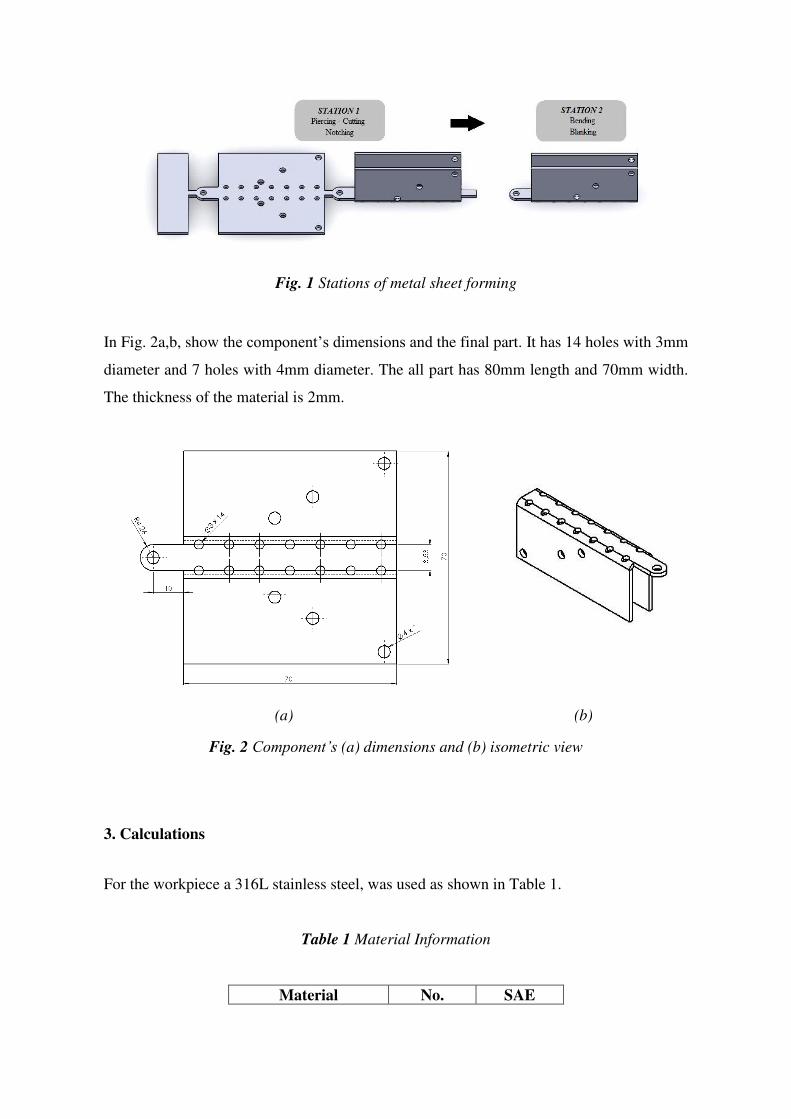
Fig. 1 Stations of metal sheet forming
In Fig. 2a,b, show the component’s dimensions and the final part. It has 14 holes with 3mm
diameter and 7 holes with 4mm diameter. The all part has 80mm length and 70mm width.
The thickness of the material is 2mm.
(a) (b)
Fig. 2 Component’s (a) dimensions and (b) isometric view
3. Calculations
For the workpiece a 316L stainless steel, was used as shown in Table 1.
Table 1 Material Information
Material No. SAE

1.4404 316L
Thickness, t 2 mm
Shear strength, fs 418 MPa
Yield strength, fy 290 MPa
Tensile strength, ft 558 MPa
Young modulus, E 193 GPa
The components of the die have been calculated by mathematical formulas and empirical
data, as presented in the next sections.
3.1 Total force
A. Cutting Force
During punching operations (Fig.3) such as piercing and blanking, the cutting force
applied in the punch can be calculated using formula (1)[12,13].
𝐅𝐜 = 𝐟𝐬 × 𝐂 × 𝐭 (1)
where,
fs = shear strength of material (N/mm2)
C = cut length (mm)
t = sheet thickness (mm)
So, in our case we have:
Fig.3 Part cut outline

Cut length calculation:
C1 = 4 × π × 7 = 87.99 mm C2 = 3 × π × 14 = 131.88 mm C3 = 169.18 + 4.16 + 4.00 = 177.34 mm Ct = 𝐶1 + 𝐶2 + 𝐶3 = 397.21 𝑚𝑚
Total cut force: Fc = 418 N mm2⁄ × 397.21 mm × 2 mm = 332,068 N = 33.86 tn
B. Bending Force
A U-bend operation can be calculated using formula (2).
𝐅𝐛 = 𝟐.𝟔𝟔 × 𝐟𝐭 × 𝐋 × 𝐭𝟐𝑾 (2)
where,
ft = tensile strength of material (N/mm2)
L = transverse length of bend (mm)
t = sheet thickness (mm)
W = width of channel (mm)
So, in our case:
Fb = 2.66 × 558 𝑁 𝑚𝑚2⁄ × 70 mm × 4 mm214 𝑚𝑚 = 29,686 𝑁 = 3.03 𝑡𝑛
C. Total Force
Due to friction between various components of the die, the cutting force must be increased
by 20% [14]. F = 1.2 × Fc + Fb = 428,168 N = 43.66 tn ≈ 44 tn
3.2 Strip economy factor

𝛈 = 𝐀 × 𝐑𝐁 × 𝐕 × 𝟏𝟎𝟎% [3]
where,
B = strip width (mm)
V = progression (mm)
A = part area without holes (mm2)
R = number of part rows
So, in our case: η = 5,013.77 mm2 × 170.0 mm × 90.0 mm × 100% = 79.6%
3.3 Definition of pressure center point
During the press working process of the shearing-cut and bending progressive die, the
position of the die’s pressure center has a direct impact on whether the die can work
accurately in balance.
In Fig. 4, are presented the distances from the zero point (left corner).
Fig. 4 Distances from (0,0)

For X and Y axis:
𝚾 = (∑ 𝐅𝐦𝐢 )× 𝐗𝐢𝐧𝐢=𝟏∑ 𝐅𝐦𝐢 𝐧𝐢=𝟏 (4)
𝐘 = (∑ 𝐅𝐦𝐢 )× 𝐘𝐢𝐧𝐢=𝟏∑ 𝐅𝐦𝐢 𝐧𝐢=𝟏 (5)
So, in our case:
Pressure center point = (49.31 , 95.00)
3.4 Springback
Springback occurs when a metal is bent and then tries to return to its original shape. After
a bending operation, residual stresses will cause the sheet metal to spring back slightly.
Due to this, it is necessary to over-bend the sheet an amount to achieve the desired bend
radius and bend angle.
The springback radius can be calculated by formula (6)[15].
𝐑𝐢𝐑𝐟 = 𝟒 × (𝐟𝐲×𝐑𝐢𝐄 ×𝐭 )𝟑 − 𝟑 × (𝐟𝐲×𝐑𝐢𝐄 ×𝐭 ) + 𝟏 (6)
where,
Ri = initial radius (mm)
Rf = final radius (mm)
fy = material yield strength (MPa)
t = sheet thickness (mm)
E = Young’s modulus (MPa)
So, in our case:
1.74Rf = 4 × ( 290 × 1.74193,000 × 2)3 − 3 × ( 290 × 1.74193,000 × 2) + 1 => 1.74Rf = 0.9961 => => Rf = 1.747 mm
The springback angle can be calculated by formula (7).
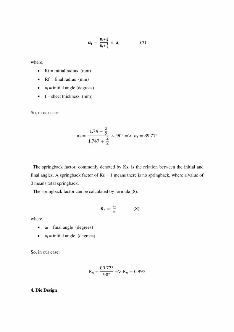
𝛂𝐟 = 𝐑𝐢+ 𝐭𝟐𝐑𝐟+ 𝐭𝟐 × 𝐚𝐢 (7)
where,
Ri = initial radius (mm)
Rf = final radius (mm)
ai = initial angle (degrees)
t = sheet thickness (mm)
So, in our case:
αf = 1.74 + 221.747 + 22 × 90° => αf = 89.77°
The springback factor, commonly denoted by Ks, is the relation between the initial and
final angles. A springback factor of Ks = 1 means there is no springback, where a value of
0 means total springback.
The springback factor can be calculated by formula (8).
𝐊𝐬 = 𝐚𝐟𝐚𝐢 (8)
where,
af = final angle (degrees)
ai = initial angle (degrees)
So, in our case:
Ks = 89.77°90° => Ks = 0.997
4. Die Design
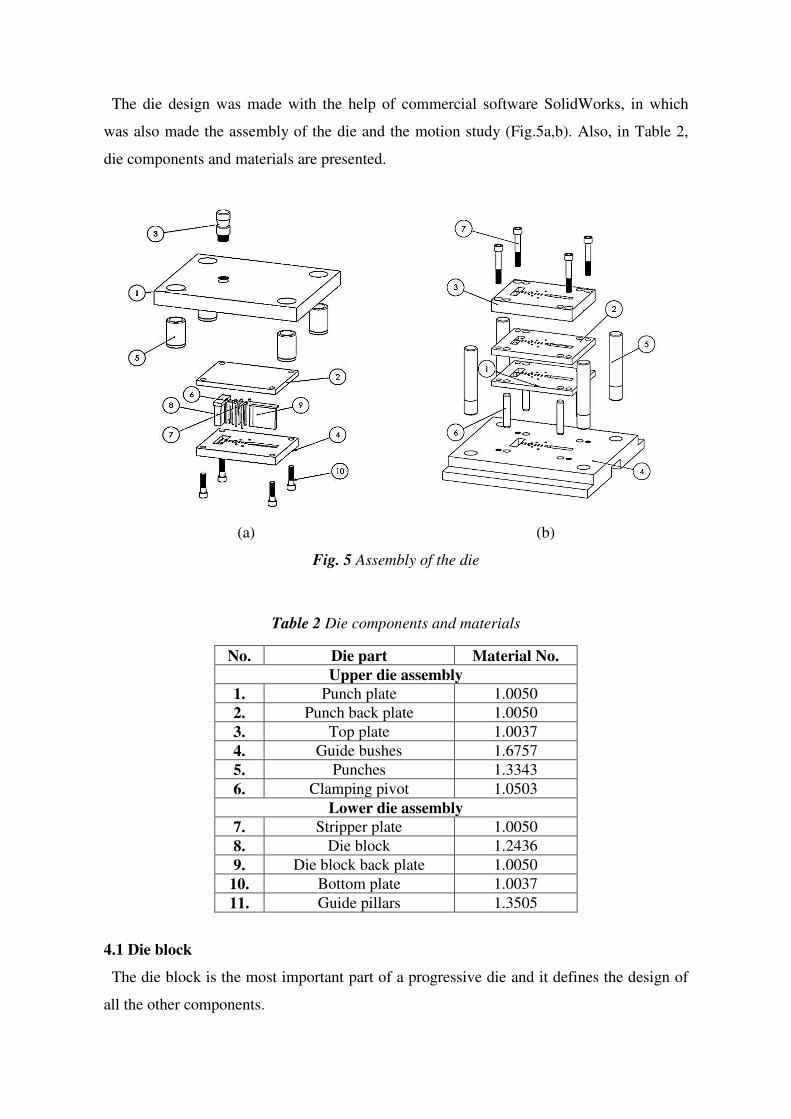
The die design was made with the help of commercial software SolidWorks, in which
was also made the assembly of the die and the motion study (Fig.5a,b). Also, in Table 2,
die components and materials are presented.
(a) (b)
Fig. 5 Assembly of the die
Table 2 Die components and materials
No. Die part Material No.
Upper die assembly
1. Punch plate 1.0050
2. Punch back plate 1.0050
3. Top plate 1.0037
4. Guide bushes 1.6757
5. Punches 1.3343
6. Clamping pivot 1.0503
Lower die assembly
7. Stripper plate 1.0050
8. Die block 1.2436
9. Die block back plate 1.0050
10. Bottom plate 1.0037
11. Guide pillars 1.3505
4.1 Die block
The die block is the most important part of a progressive die and it defines the design of
all the other components.
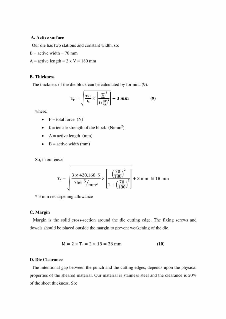
A. Active surface
Our die has two stations and constant width, so:
B = active width = 70 mm
A = active length = 2 x V = 180 mm
B. Thickness
The thickness of the die block can be calculated by formula (9).
𝐓𝐫 = √ 𝟑×𝐅𝐟𝐭 × [ (𝐁𝐀)𝟐𝟏+(𝐁𝐀)𝟐] + 𝟑 𝒎𝒎 (9)
where,
F = total force (N)
ft = tensile strength of die block (N/mm2)
A = active length (mm)
B = active width (mm)
So, in our case:
𝑇r = √ 3 × 428,168 Ν756 Ν mm2⁄ × [ ( 70180)21 + ( 70180)2] + 3 mm ≅ 18 mm
* 3 mm resharpening allowance
C. Margin
Margin is the solid cross-section around the die cutting edge. The fixing screws and
dowels should be placed outside the margin to prevent weakening of the die.
M = 2 × Tr = 2 × 18 = 36 mm (10)
D. Die Clearance
The intentional gap between the punch and the cutting edges, depends upon the physical
properties of the sheared material. Our material is stainless steel and the clearance is 20%
of the sheet thickness. So:

u = 20% × t = 0.2 × 2 = 0.4 mm (11)
E. Width and length
The total width of the die block can be calculated by formula (12).
𝐖𝐝 = 𝐁 + 𝟐 × 𝐌 + 𝟑 × 𝐝𝐤 (12)
where,
B = active width (mm)
M = margin (mm)
dk = screw head diameter (mm)
So, in our case: Wd = 70 + 2 × 36 + 3 × 16 = 190 mm (min) The total length of the die block can be calculated by formula (13).
𝐋𝐝 = 𝐀 + 𝟐 × 𝐌 (13)
where,
A = active length (mm)
M = margin (mm)
So, in our case: Ld = 180 + 2 × 36 = 252 mm (min)
4.2 Stripper plate
The stripper plates guide the punches through the sheet and also helps the operator with
the manual feed of the strip.
W = 190 mm, L = 250 mm 𝐭𝐬 = 𝟏𝟑 × 𝐁 × +𝟐 × 𝐭 + 𝐡𝐢𝐧 (14)
where,
B = sheet width (mm)

t = sheet thickness (mm)
hin = sheet opening height (mm)
So, in our case: ts = 13 × 70 mm × +2 × 2 mm + 5 mm = 32.33 ≅ 33 mm
4.3 Die block back plate - punch back plate
These components are made by softer steel in order to the die block and the punches do
not break or bend. Also, they are interchangeable because they are simpler and cheaper
parts.
W = 190 mm, L = 250 mm
tbp = 10 to 15 mm = 15 mm
4.4 Top plate
The top plate is mounted on the press and it is standardized. Its dimensions depend on the
width and length on the die block.
Width-Length: A x B = 450 x 365 mm
Height: C = 45 mm
Guide bushes insert diameter: F = 55 mm
4.5 Bottom plate
The bottom plate is mounted on the bed of the press and it is also standardized. Its
dimensions depend on the width and length of the die block.
Width-Length: A x B = 450 x 365 mm
Height: C = 55 mm
Guide pillars insert diameter: E = 38 mm
4.6 Punch plate
On the punch plate are mounted the cutting and bending punches. The punch-head inserts
are slightly bigger in case they deform so they do not stick in the plate.
W = 190 mm, L = 250 mm
tpp = 12 to 25 mm = 25mm
4.7 Guide bushes
The guide bushes guide the pillars so the whole assembly is perfectly straight and also
lubricate the pillars. They are standardized.
Outside diameter: Dout = 55 mm
Inside diameter: Din = 38 mm
Height: H = 85 mm
4.8 Guide pillars
The guide pillars guide with the help of the bushes the whole die. They are press fitted on
the bottom plate. Their height depends on the height of the die. They are also standardized.
Diameter: D = 38 mm
Bottom diameter: Dbottom = 38.013 mm
Length: L = 200 mm
4.9 Punches
In this die assembly there are four kinds of punches. There two standardized circular
punches, a custom-made cutting punch and a custom-made bending punch.
First, we should calculate the critical length of the punches. Τhe lengths of the punches
are calculated from Euler’s formula (15).
𝐋𝐜𝐫 = √𝐧 × 𝛑𝟐 ×𝐄×𝐈 𝐏 (15)
where,

n = factor accounting for the end conditions
E = Young’s modulus (N/mm2)
P = load (N)
I = Moment of inertia (mm4)
So, in our case:
A. D3 piercing punch
Lcr = √2 × π2 × 200,000 Nmm2 × 3.98 mm47,875.12 N = 44.7 mm
B. D4 piercing punch
Lcr = √2 × π2 × 200,000 Nmm2 × 12.57 mm410,508.52 N = 68.7 mm
C. Notching punch
Lcr = √2 × π2 × 200,000 Nmm2 × 42,420.31 mm4141,434.48 N = 1,088.1 mm
D. Bending-blanking punch
Lcr = √2 × π2 × 200,000 Nmm2 × 1,755.02 mm436,507.76 N = 435.6 mm
During the production, all the punches must have the same, safe length. So, for our case
we choose 40 mm.
5. Finite Element Analysis

The analysis of the parts was made with the commercial code Ansys Workbench. The
type of the analysis we chose is Static Analysis and every part had a fixture at one end and
the other end was free. The right load for each part was applied at the free end.
In Fig. 6-15, are presented the results of the F.E analysis for the most important
components of the die.
All the parts can withstand the load that is applied to them without failure according to
Von-Mises criterion of failure.
Fig. 6 Deformation of Die block
Fig. 7 Von-Mises stress of Die block

Fig. 8 Von-Mises stress of Notching punch
Fig. 9 Deformation of Notching punch
Fig. 10 Von-Mises stress of D3 piercing punch

Fig. 11 Deformation of D3 piercing punch
Fig. 12 Von-Mises stress of D4 piercing punch
Fig. 13 Deformation of D4 piercing punch
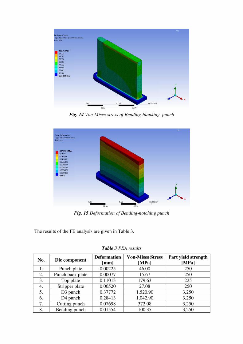
Fig. 14 Von-Mises stress of Bending-blanking punch
Fig. 15 Deformation of Bending-notching punch
The results of the FE analysis are given in Table 3.
Table 3 FEA results
No. Die component Deformation
[mm]
Von-Mises Stress
[MPa]
Part yield strength
[MPa]
1. Punch plate 0.00225 46.00 250
2. Punch back plate 0.00077 15.67 250
3. Top plate 0.11013 179.63 225
4. Stripper plate 0.00520 27.08 250
5. D3 punch 0.37772 1,520.90 3,250
6. D4 punch 0.28413 1,042.90 3,250
7. Cutting punch 0.07698 372.08 3,250
8. Bending punch 0.01554 100.35 3,250

9. Guide pillars 0.07244 718.18 1,390
10. Die block 0.00103 19.80 860
11. Die block back
plate 0.00083 19.32 250
12. Bottom plate 0.00462 30.94 225
In conclusion according to the Fig. 6-15 and Table 3, the results of Von-Mises stress and
deformation of the most important parts of the die specifically the punches and the die, can
withstand the load of the procedure.
6. Conclusions
In this work a progressive die was developed, in order to produce a complex metal part
with four different manufacturing processes, piercing, notching blanking and bending, with
as few as possible stations.
The components of the die have been calculated by mathematical formulas and Finite
Element Analysis tools.
The proposed approach is based on real manufacturing data, in order to be easily produced.

Ethical Approval
For this type of study formal consent is not required.
Consent to Participate
Informed consent was obtained from all individual participants included in the study.
Consent to Publish
The participants have consented to the submission of the case report to the journal.
Author contribution
The manuscript was written through contributions of all authors. All authors have given
approval to the final version of the manuscript.
Funding
No funds, grants, or other support was received.
Competing Interests
There are no relevant financial or non-financial competing interests to report.
Availability of data and materials
All the data (numerical, figures, diagrams, tables, etc.) used to support the findings of our
study are included within the article. Thus, data sharing regarding the aforementioned
paper is totally allowed and any reader can access the data supporting the conclusions of
the study.
ORCID iDs
Tsirkas A. Sotirios
https://orcid.org/0000-0001-7770-1321
Grammatikopoulos Spyridon
https://orcid.org/0000-0001-9787-9071

References
[1] Pawar S.,Dalu R. (2014), Compound Die Design: A Case Study, International Journal
of Science and Research (IJSR) 3(5):389-392
[2] Choi J. C., Kim B. M., Kim Chul (1999), An Automated Progressive Process Planning
and Die Design and Working System for Blanking or Piercing and Bending of a Sheet
Metal Product, Int J Adv Manuf Technol 15:485–497
[3].Bhajantri V., Kapashi G., Bajantri S. (2014), Analysis of Progressive Dies,
International Journal of Engineering and Innovative Technology (IJEIT) 3(7):223-231.
[4] Zhi-Xin Jia, Hong-Lin Li, Xue-Chang Zhang, Hong-Bing Wu, Ming-Cai Fang (2010),
Study on the correlated design method of plate holes for progressive dies based on
functional feature, Int J Adv Manuf Technol 49:1–12
[5] Zhi-Xin Jia, Hong-Lin Li, Xue-Chang Zhang, Ji-Qiang Li, Bo-Jie Chen (2011),
Computer-aided structural design of punches and dies for progressive die based on
functional component, Int J Adv Manuf Technol 54:837–852
[6] Zone-Ching Lin, Chun-Yao Hsu (1996), An Investigation of an Expert System for
Shearing Cut Progressive Die Design, Int J Adv Manuf Technol 11:1-11
[7].Zone-Ching Lin, Ching-Hua Deng (2001), Analysis of a torque equilibrium model and
the optimal strip working sequence for a shearing-cut and bending progressive die, Journal
of Materials Processing Technology 115(3):302-312
[8]. Mastanamma Ch., Prasada Rao K., Venkateshwara Rao M. (2012), Design and
Analysis of Progressive Tool, International Journal of Engineering Research &
Technology (IJERT) 1(6):1-10
[9]. Ramegowda D., Madhusudhana M. (2015), Design of Blanking Punch and Die for
Cam Head Washer Component using Finite Element Analysis, Journal of Engineering
Research & Technology (IJERT) 4(7):410-414,
[10] Effect of two-stage press blanking on edge stretchability with third-generation
advanced high-strength steels
[11]. Kumaresh A.K., Balaji B., Raj Kumar M. (2016), Design and Analysis of Punching
Die, Journal of Engineering Research & Technology (IJERT) 5(4):249-255
[12]. Prakash H. Joshi (1999), Press Tools: Design and Construction, Wheeler Publishing,
New Delhi
[13]. Paquin J.R. (1987), Die Design Fundamentals, Industrial Press Inc., New York

[14]. Smith D. (1990), Die Design Handbook, Society of Manufacturing Engineers,
Michigan
[15].Suchy I. (1988), Handbook of Die Design, McGraw-Hill Handbooks, New York

Figures
Figure 1
Stations of metal sheet forming
Figure 2
Component’s (a) dimensions and (b) isometric view

Figure 3
Part cut outline

Figure 4
Distances from (0,0)

Figure 5
Assembly of the die

Figure 6
Deformation of Die block
Figure 7
Von-Mises stress of Die block
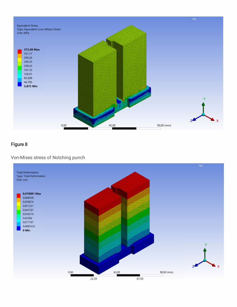
Figure 8
Von-Mises stress of Notching punch

Figure 9
Deformation of Notching punch
Figure 10
Von-Mises stress of D3 piercing punch

Figure 11
Deformation of D3 piercing punch

Figure 12
Von-Mises stress of D4 piercing punch

Figure 13
Deformation of D4 piercing punch

Figure 14
Von-Mises stress of Bending-blanking punch

Figure 15
Deformation of Bending-notching punch