Design and Analysis Issues of Integrated Control Systems ...
78
NASA Contractor Report 186022 // / Design and Analysis Issues of Integrated Control Systems for High-Speed Civil Transports Craig A. McCarty, John B. Feather, John R. Dykman, Mark A. Page, and John Hodgkinson Contract NAS2-12722 May 1992 (NASA-CR-186022) DESIGN AND ANALYSIS ISSUES OF INTEGRATED CONTROL SYSTEMS FOR HIGH-SPEED CIVIL TRANSPORTS Final Report (Douglas Aircraft Co.) 73 p G3108 N92-31656 Unclas 0109346 NA__ National Aeronautics and Space Administration
Transcript of Design and Analysis Issues of Integrated Control Systems ...

NASA Contractor Report 186022
// /
Design and Analysis Issues ofIntegrated Control Systems forHigh-Speed Civil Transports
Craig A. McCarty, John B. Feather, John R. Dykman, Mark A. Page,and John Hodgkinson
Contract NAS2-12722
May 1992 (NASA-CR-186022) DESIGN ANDANALYSIS ISSUES OF INTEGRATED
CONTROL SYSTEMS FOR HIGH-SPEED
CIVIL TRANSPORTS Final Report
(Douglas Aircraft Co.) 73 p
G3108
N92-31656
Unclas
0109346
NA__National Aeronautics and
Space Administration


NASA Contractor Report 186022
Design and Analysis Issues ofIntegrated Control Systems forHigh-Speed Civil Transports
Craig A. McCarty, John B. Feather, John R. Dykman, Mark A. Page, and John HodgkinsonDouglas Aircraft Company, New Programs and Technology, Long Beach, California
Prepared forPRC Inc.Edwards, CaliforniaUnder Contract ATD-91-DAC-7103
1992
N/LRANational Aeronautics andSpace Administration
Dryden Flight Research FacilityEdwards, California 93523-0273


CONTENTS
FIGURES
ABSTRACT
NOMENCLATURE
INTRODUCTION
IDENTIFICATION OF THE DESIGN AND ANALYSIS ISSUES
Relevant Characteristics of Supersonic Aircraft .........................
Aerodynamic Stability and Control . ...........................
Pitch stability and control ..............................
Directional stability and control ...........................
Lateral stability and control .............................
Aeroelasticity ........................................
Leading-edge vortex of the advanced supersonic transport ............
Flutter of the advanced supersonic transport ....................
Static aeroelastic corrections ............................
Structural mode control systems ..........................
Acoustics ..........................................
Airframe-Propulsion Interactions ..............................
Interactions with airframe dynamics ........................
Advanced Supersonic Transport Flight Controls .....................
System complexity ..................................
Unstable aircraft dynamics .............................
Ride and handling qualities .............................
Flexible aircraft dynamics ..............................
High-Speed Civil Transport Control Requirements .......................
Configuration ........................................
Aerodynamic Stability and Control ............................
Pitch requirements ..................................
Directional requirements ..............................
Lateral requirements .................................
Aeroelasticity ........................................
Leading-edge vortex effects .............................
Flutter and its suppression .............................Static aeroelastic considerations ...........................
Structural mode control system ...........................Laminar flow control ................................
Gust load alleviation system ............................
Spoilers .......................................
Aemthermoelasticity .................................
Acoustics ..........................................
2
3
3
3
3
4
5
5
5
6
6
6
6
7
8
9
9
10
11
11
12
12
12
13
13
14
14
14
15
15
15
15
15
15
15
16
PRECEDING PAGE BLANK NOT FILMED 1 !
.°°
111

Airframe-Propulsion Interactions ..............................
Internal inlet--engine,--nozzle interactions ......................
Interactions with airframe dynamics ........................
Flishtpath Management ...................................
Flightpath management concepts ..........................
Fuel management systems ..............................
Control system--composites interaction .......................
Control Design Technology and Methodology Issues ......................
Aerodynamic Stability and Control ............................
Aeroelasticity ........................................
State of the art ....................................
Shortcomings cf the state of the art ........................
Four issues ......................................
Plan with tasks and schedule ............................
Acoustics ..........................................
Airframe-Propulsion Interactions ..............................
Inlet--engine-nozzle integrated control ......................
Integrated flight-propulsion control. ........................
Control Augmentation and Flightpath Management ....................
Controlling unstable, fTexible aircraft. .......................
Flightpath management. ..............................
Fuel management. .................................
PRIORITIZATION OF THE DESIGN AND ANALYSIS ISSUES
TECHNOLOGY DEVELOPMENT PLANS
CONCLUSION
REFERENCES
16
16
16
17
17
17
18
18
18
20
20
21
21
21
22
22
23
24
24
24
24
25
25
27
27
27
iv

2
7
8
9
10
11
12
13
14
15
16
17
18
19
20
21
22
FIGURES
Advanced supersonic transport tail-off pitching moment coefficient for various flap de-
flections ............................................
Advanced supersonic transport tail-off pitching moment coefficient with the leading edge
deflected ...........................................
Advanced supersonic transport tail-on pitching moment for several tail incidence settings.
Advanced supersonic transport tail-on pitching moment characteristics used to calculate
downwash ..........................................
Estimated yawing moment coefficient as a function of sideslip angle ...........
Estimated advanced supersonic transport yawing moment coefficient as a function of
sideslip angle .........................................
Estimated advanced supersonic transport yawing moment coefficient caused by rudder
deflection ...........................................
Advanced supersonic transport lateral control system effectiveness ............
Advanced supersonic transport leading- and trailing-edge flaps, spoiler-deflector, and
inverted spoiler--deflector ..................................
Variable geometry features of NASA low-speed advanced supersonic transport model.
Mixed compression supersonic
Advanced supersonic transport
Advanced supersonic transport
Advanced supersonic
Advanced supersonic
Advanced supersonic
Advanced supersonic
Advanced supersonic
transport
transport
transport
transport
transport
inlet performance .....................
general configuration drawing ...............
longitudinal control law for landing approach ......
lateral control law for landing approach .........
handling qualifies rating ..................
ride qualities evaluation results ..............
flexible mode control law .................
flexible mode suppression control results .........
Design features and key technologies ............................
Technology development plan for defining large transport flying quality criteria .....
Technology development plan for defining the benefits and costs of reduced inlet stability
margins ............................................
Technology development plan for defining control system validation process ......
31
32
33
34
35
36
37
38
39
40
41
42
43
44
45
46
47
48
49
50
51
52

23
24
25
26
27
28
29
30
31
32
33
34
35
36
Technology development plan for generating unsteady aero data for spoiler-slot deflectors.
Technology development plan for defining the takeoff and landing profile constraints..
Technology development plan for defining the reduced inlet stability control system
architecture ..........................................
Technology development plan for developing a unified rigid body analytical model...
Technology development plan for developing robust advanced control synthesis and
analysis tools .........................................
Technology development plan for developing the integrated flight-propulsion control
system architecture ......................................
Technology development plan for defining benefits and costs of advanced control modes.
Technology development plan for demonstrating integrated control of unstable, flexible
aircraft ............................................
Technology development plan for developing aircraft controls for large fuel fraction
variation ...........................................
Technology development plan for improving propulsion system performance predictionmodels ............................................
Technology development plan for defining advanced high-lift system stability and controlcharacteristics ........................................
Technology development plan for defining low-boom planform stability and control
characteristics ........................................
Technology development plan for using multidisciplinary optimization ..........
Technology development plan for developing constrained optimization synthesis and
analysis tools .........................................
53
54
55
56
57
58
59
60
61
62
63
64
65
66
vi

ABSTRACT
A study was conducted to identify and rank the critical guidance and control design and analysis issues
for an economically viable and environmentally acceptable high-speed civil transport, and to define
technology development plans addressing the issues. The issues were identified in a multistep process.
First, pertinent literaatre on supersonic cruise aircraft was reviewed, and experts were consulted to
establish the fundamental characteristics and problems inherent to supersonic cruise aircraft. Next, the
advanced technologies and strategies being pursued for the high-spe_ civil transport were considered
to identify any additional unique control problems the transport may have. Finally, existing
technologies and methods were examined to determine their shortcomings for designing and analyzing
control systems for high-spe_ civil transport. Three priority levels - mandatory, highly beneficial, and
desirable - were established. Within each of these levels, the issues were further ranked. Technology
development plans for each issue were defined. Each plan contains a task breakdown and schedule.
NOMENCLATURE
AST
ATO
ATP
CFD
c.g.DAC
DOF
EPR
FAA
FLADE
HIDEC
HSCT
ISSD
MAC
SCAR
SSD
SST
TBE
TET
advanced supersonictransport
authority to offer
authority to proceed
computational fluid dynamics
center of gravity
Douglas Aircraft Company, Long Beach, California
degree of freedom
engine pressure ratio
Federal Aviation Administration
fan on blade
highly integrated digital electronic control
high-speed civil transport
inverted spoiler slot deflector
mean aerodynamic chord
supersonic cruiseaircraftresearch
spoiler-slot deflector
supersonic transport
turbine bypass engine
turbine entrance temperature
gT2
angle of attack,deg
sideslipangle,deg
landing coefficientof lift
accelerationof gravity
time to double amplitude
minimum aircontrolspeed
Symbols

Vmc9
vo
minimum ground control speed
minimum landing control spell
maximum dive speed
INTRODUCTION
Studies of the potential of a high-speed civil transport (I-ISCT) project that for the 2000 to
2025 period, sufficient passenger traffic will exist to support an HSCT fleet; but such transports must
be economically viable and environmentally acceptable (ref. 1). More specifically, the operating costs
must be sufficiently low so that airlines will not have to charge premium fares. In addition, the aircraft
must operate with extremely low toxic emission levels, meet airport noise regulations, and have an
acceptable sonic-boom signature or be efficient enough to operate subsonically for 20 to 25 percent of
the flight. Current production level technologies and methodologies are insufficient for designing and
producing a supersonic cruise commercial transport that meets these economic and environmental
goals.
The NASA High-Speed Research Program is developing the technologies and methodologies required
to overcome the obstacles to economic viability and environmental acceptability. The technologies and
strategies being pursued include low oxides of nitrogen (NOx) combustors, efficient fuel consumption,
careful integration of the inlet with the engine and the nacelle with the airframe, lightweight materials
and structures, advanced operating procedures to minimize noise, low-speed high-lift devices, variable
geometry propulsion systems, and a highly automated flight deck with synthetic vision. The High-
Speed Research Program has two phases. Phase 1 is directed at resolving the environmental issues; it
began in 1990, and is scheduled to run through 1995. Phase 2 is directed at developing the enabling
technologies; it is scheduled to begin in 1993 and run through 1998. As part of the planning for
phase 2, NASA is formulating a supersonic cruise technology program to address the guidance and
control systems design and analysis techniques required for a successful next-generation supersonic
cruise commercial transport.
The overall objective of this study was to help NASA define the technology program to address the
required guidance and control systems design and analysis techniques. The design and analysis of
control systems includes defining the requirements, developing the analytical models, synthesizing and
implementing the control laws, and testing and verifying the system. Three tasks were defined to meet
the overall objective: (1) identify the critical technology needs, (2) rank the critical technology needs,
and (3) develop a technical plan to address the key technology shortfalls.
This report is organized as follows. In the next section, a brief description of the process used to
carryout task 1 and the results of its application axe presented. Next, the critical technology needs are
ranked. Then a technical plan for each need is presented. The final section summarizes the
conclusions of this study.
2

IDENTIFICATION OF THE DESIGN AND ANALYSIS ISSUES
This section presents the results of the critical technology identification process. A three-step process
was used to identify the critical technology needs. The first step was to identify the control problems
that have to be solved. The second step was to determine what technologies and methodologies are
required to solve the control problems. The third step was to compare the required technologies and
methodologies with the state of the art to identify key shortcomings, i.e., the technology and
methodology issues that need to be addressed in phase 2 of the High-Speed Research Program. The
organization in the following three sections primarily corresponds to the engineering groups assigned
to this study: aerodynamic stability and control, aeroelasticity, acoustics, flight controls, and
airframe-propulsion integration.
Relevant Characteristics of Supersonic Aircraft
Since only a minimal database and a preliminary configuration definition exist for the HSCT, the
control problems could not be identified directly. Therefore, a technology baseline to compare the
HSCT with, was defined by reviewing pertinent reports on relevant supersonic aircraft (e.g., Concorde,
SR-71/YF-12, XB-70) and supersonic research programs (e.g., supersonic cruise aircraft research
(SCAR) and advanced supersonic transport (AS'I)), and by consulting McDonnell Douglas experts.
The information presented in this section and in the section entitled High-Speed Civil Transport
Control Requirements constitutes the results of the first step in the technology identification process.
Aerodynamic Stability and Control
The aerodynamics of the HSCT represent a major part of the problem statement for the control-system
designer. Previous supersonic aircraft experience has exposed many problems that we will face in
developing a successful HSCT. This section summarizes those aerodynamic issues that are relevant tothe HSCT.
Pitch stability and control.--All supersonic aircraft experience an aft shift of the aerodynamic
center at Mach 1 and beyond. This shift increases the pitch stability and required trim at supersonic
speeds. The tailless Concorde addresses this problem through an aggressive center-of-gravity (c.g.)
management system that pumps fuel aft above Mach 1. Similar systems have been used on many
supersonic aircraft.
The Douglas Aircraft Company (DAC) and Boeing (Seattle, Washington) supersonic transports (SSTs)
took a different approach. A cranked-arrow wing was selected to minimize the aerodynamic center
shift. This, with a conventional tail, eliminated the need for a c.g. management system on the AST.
The cranked-arrow wing works on the principle that if the inboard sweep is higher than the outboard
sweep, spanload moves inboard as Mach is increased. Since the inboard panel is forward of the
outboard panel, this offsets the aft shift of the sectional lift.
Despite the advantages of the cranked-arrow wing in reducing the Mach effect on stability, it does not
solve high angle-of-attack (c_) instability. At high c_, strong coherent vortices form along the wing's
leading edge and on the forebody. Both sets of vortices produce upward normal forces forward of the
3

c.g., and are therefore destabilizing. Figures 1 and 2 show that at a = 5 ° (vortex onset), a 30-percent
mean aerodynamic chord (MAC) instability developed for the AST in the tail-off configuration. Wing
leading-edge flaps that suppress the wing vortex formation improve stability by roughly 10-percent
MAC. However, the airplane is still unstable. These phenomena are also present in the F-16XL,
which features a cranked-arrow wing in a tailless layout.
Figures 3 and 4 show that the horizontal tail adds a small amount of stability below a = 5 °. Above
= 5 °, the wing and forebody vortices produce a downwash gradient of one, which cancels the tail
contribution to stability. Note, however, that the tail was still an effective trimmer-controller. Since
the AST was unstable, an aggressive stability augmentation system was required. The conventional
tail demonstrated excellent conu'ol power and linearity, making it an ideal control effector.
The horizontal tail of the AST features an all flying stabilizer with a geared elevator for control. The
dedicated tail-plane with a healthy tail arm was selected to allow for high-lift flaps on the wings. A
canard was not selected since it would have penetrated the pressure vessel, interfering with the cabin
layout. The tail was sized by the nosewheel lift-off maneuver;, which is primarily an elevator power
issue. Landing trim was not critical, since the pitch instability offset much of the flap pitching
moments at landing coefficient of lift (UL).
The Concorde has simple-hinged trailing-edge elevons for pitch trim and control. The tailless
Concorde lacks high-lift devices, since the trimmer and flaps would have had the same lever-arm
yielding no trimmed lift improvement. This required large approach attitudes and a large wing to
compensate for the lack of flaps. The XB-70, Saab Viggen & Grippen, and Dassault Rafale feature
canards to avoid the inefficiencies of trimming with elevons. Similarly, the Soviet TU-144 and an
experimental Dassault Mirage sport retractable canard "moustaches" to improve the trimmed lift in
landing without paying additional cruise drag. However, a conventional tail is still a very efficient
layout for trimming statically stable configurations, if it has a healthy lever arm.
Directional stability and eontrol.--The directional stability of most supersonic aircraft decrea_et
with increasing Mach number. This is largely the result of the reduction in side wash gradient at the
tail for high Math numbers. Most supersonic aircraft, therefore, feature large vertical tails.
The AST's directional stability was low, but not unstable, at supersonic speeds. However, at low speed
and high angle of attack, the forebody and wing vortices produce a negative sidewash at the vertical
tail, causing the net stability to drop to nearly zero over 4-7 ° of sideslip (see figs. 5 and 6).
Fortunately, since there is also a high level of downwash at the empennage, there are no low-energy
wakes from the fuselage or wing to engulf the vertical tail. As a result, the rudder effectiveness is
almost unaffected by o_, and remains a powerful and linear control effector (see fig. 7). The Concorde
and SR-71 address the high c_ instability through use of forebody strakes chines, which produce
stabilizing suction loads on the forebody.
The AST features a conventional vertical tail and rudder. Minimum ground control speed (Vmcg) with
an engine failure was the critical sizing condition for the vertical tail (rudder control power). The
crosswind landing de-crab maneuver was not critical since the directional stability is low at landing or.
Further, supersonic inlet unstart was not critical, even with a two-engine "zipper" unstart.
4

Unstart compensation is automatic on the Concorde, which deflects the rudder and ailerons based on
compressor entry pressure differences. A totally different approach is taken by the SR-71, which
automatically unstarts the good engine to compensate for the initial unstart, then restarts both in unison.
Lateral stability and control.--Swept wings produce high lateral stability at high lift, especially
if leading-edge vortices form. However, this stability becomes a liability for intentional sideslip
maneuvers like a landing crosswind de-crab, since a large amount of lateral control is required to hold
down the windward wing. The AST had well behaved but high lateral stability. This required
75 percent of the available lateral control for de-crab in a 31-kn crosswind, and represented the critical
lateral control condition. The low-speed lateral controls that were tested at NASA-Langley on the
AST consisted of outboard ailerons and inboard, mid, and outboard spoilers. The ailerons were very
effective at all a's, and the same was true for the spoilers as long as the flaps were deflected. At zero
flap deflection, the spoilers were anemic or reversed, especially the mid spoiler (fig. 8).
Supersonically, the AST ailerons were locked out because of aeroelastic reversal. Since simple
spoilers are ineffective at supersonic and near-stall conditions, spoiler-slot deflectors (SSDs) and
inverted spoiler-slot deflectors (ISSDs) were used. Supersonically, camber changes do not change lift,
only an o_ change does. Spoilers cause the flow to separate, but in supersonic flow it can reattach
yielding no effective o_ change. In contrast_ SSDs partition the wing section into two panels with new
ot's. The SSDs and ISSDs double as traditional spoilers for low-speed operation (figs. 9 and 10). The
SSD sizing was based on inlet unstart rolling moments (for under-wing engines), which can produce
very high roll accelerations (20 deg/sec 2) because of the low roll inerfias of these aircraft (ref. 2).
The Concorde and SR-71 use elevons exclusively for lateral control, while most supersonic fighters
use the tail-plane for supersonic roll control. Inboard elevon deflection for roll was reduced on the
Concorde to limit adverse sidewash on the fin.
Aeroelasticity
The aeroelastic properties of the HSCT also represent a major part of the problem statement for the
control system designer. Previous supersonic aircraft experience has exposed many problems that willbe faced to develop a successful HSCT. In this section, aeroelastic issues relevant to the HSCT will
be summarized.
Leading-edge vortex of the advanced supersonic transport.raThe large leading-edge sweep of
the AST cranked-arrow wing results in the formation of a vortex. This vortex is present at all c_'s; its
strength is small for low c_ and increases with c_. Wind tunnel tests of a 1/10 scale AST model at low
and medium speeds (ref. 3 and 4) indicate a > 5 ° as the region of increasing importance of the
leading-edge vortex. For a up to 5 °, lift-and-moment-test results are linear and are identical with
analytical predictions that neglected leading-edge vortex effects. Lift does not vary much from
predictions for a greater than 5 °, but the pitching moment starts deviating rapidly. High-g maneuvers
are expected to occur at c_ below 10 ° and near 5 °. Therefore, it is anticipated that the leading-edge
vortex has little effect in the flight envelope, where aeroelastic considerations are important, and
probably will only impact takeoff and landing.

Flutter of the advanced supersonic transport.--The low aspect ratio, low wing thickness, and
aft-mounted engines of the AST are all detrimental to flutter speed. Previous AST flutter-analysis
results (ref. 5) indicate a large weight penalty of 6100 lb to avoid flutter below the analytical
certification requirement of 1.2 VD (VD is the maximum dive speed). This is equivalent to
approximately 10 percent of the payload. Because of unacceptable flutter speeds, the outboard wing
could not be used for fuel storage. This corresponds to a reduction of 5 to 10 percent of the total fuel
capacity. The analysis neglected transonic effects and is unconservative in predicting the transonic
flutter bucket. However, the discrepancy is believed to be small, because the AST wing thickness ratio
is low, the wing is highly swept, and the fuselage is very slender.
Static aeroelastic corrections.--Static aeroelastic corrections to the stability and control
derivatives are important for long, slender, flexible vehicles where a large fraction of its weight is fuel.
A study of this topic for the XB-70 (ref. 6) indicates a large influence on the stability and control
derivatives. A dramatic variation in the derivatives exists for changes in vehicle weight from heavyto light.
Structural mode control systems.---Structural mode control systems were implemented on the
XB-70 (ref. 7) and the B-1 (ref. 8). The B-1 system was required to control the large vibration levels
at the pilot station because of atmospheric turbulence during high-speed terrain following flight. On
both aircraft, small canards were placed near the pilot station to supply vertical and lateral
aerodynamic forces. They were actively controlled by sensing pilot station acceleration levels and
commanding the canards to dampen out the structural modes. This improved the ride quality in the
cockpit. A substantial savings in weight was achieved with this approach as compared to direct
material stiffening.
Acoustics
In addition to meeting the FAA and ICAO noise certification requirements, commercial airplanes must
comply with local airport noise restrictions. The latter could be based on single or multiple monitors
or noise footprints, and on single event maximum level or cumulative dosage. Compliance with these
requirements can be achieved through low source noise designs of the propulsion and airframe
systems and with noise-abatement flight procedures for operations in and out of airports. For example,
power cutback after reaching a certain altitude is routinely used to minimize the noise impact on
communities near the airport.
Additional noise-reduction benefits may be achievable at selected airports through effective thrust and
flightpath management. At present, Concorde minimum-noise routes have been established,
particularly at New York (JFK) and London (LHR) airports. At these airports, manual noise-abatement
procedures are being performed by the crew based on time from brake release as a function of the
following parameters: maximum take-off weight, temperature, and headwind component. During
approach operation, particularly at JFK, the Concorde adopts an automatic decelerating technique to
minimize community noise.
6

Airframe-Propulsion Interactions
All powered aircraft exhibit interactions between the airframe and the propulsion system (for example,
the coupling of speed, attitude, and altitude through thrust and pitch control). For supersonic aircraft,
especially for larger ones, the interactions are more numerous, sensitive, and complex than they are for
subsonic aircraft. Moreover, the interactions strengthen as speed is increased and as systems are
designed for overall optimum performance. Obviously, the interactions have a large impact on both
stability and efficiency. This section discusses some important interactions that the Concorde, XB-70,
and SR-71/YF- 12 exhibited.
Internal inlet-engine-nozzle interaetions.mA supersonic aircraft's propulsion system is
comprised of three primary components-an inlet, an engine, and a nozzle. As will be discussed below,
all three interact through various mechanisms.
There is a variety of inlet types (e.g., two-dimensional, axisymmetric, external compression, mixed
compression, etc.). The primary function of any inlet is to deliver a specific air supply to the engine.
When the inlet airflow capacity equals the engine demand, the inlet is said to be matched and,
assuming proper nozzle and engine settings, the propulsion system performance is optimal. At all
flight conditions, subsonic and supersonic, the consequences of not matching are significant losses of
efficiency and increased drag. At supersonic flight conditions, there exists the additional risk of inlet
unstart. Therefore, the goal is to always have the inlet matched. To compensate for changes in the
properties of the air over the entire flight envelope (i.e., takeoff, climb, cruise, approach, and landing),
the inlet is equipped with variable geometry, bleed flows, and bypass flows.
A common measure of inlet performance is pressure recovery. A typical plot of pressure recovery to
mass flow ratio for a mixed compression inlet is shown in figure 11. Off-design point operation will
occur if the inlet is oversized or undersized. When the inlet is undersized, engine demand exceeds
inlet capacity and the normal shock moves downstream. As illustrated on the right-hand side of
figure 11, the pressure recovery drops dramatically, while the mass flow ratio remains nearly constant.
The downstream movement of the normal shock also causes other problems. When the normal shock
moves downstream, it interferes with the boundary layer along the inlet walls. The turbulence caused
by the normal shock-boundary layer interference results in distorted pressure gradients at the engine
face. A distorted pressure gradient at the engine face increases for noise, reduces engine efficiency,
and can lead to compressor stall. When the inlet is oversized, its airflow capacity is greater than the
engine demand. The excess airflow must either bypass the engine via valves and ducts or backup and
spill out the front of the inlet. Either way, drag is increased and additional aerodynamic control
surface trim is required to counter the resulting forces and moments. For example, a fully opened
bypass door on the YF-12 causes a 25-percent increase in drag. At smaller openings, a 10-percent
increase in bypass flow results in a 2.5-percent increase in drag. Examples of countering control
surface requirements are given in the next section.
As discussed in reference 12, the Concorde's wide range of flight conditions necessitates a variable
geometry nozzle. The prime reason for a variable nozzle is to simultaneously achieve maximum
engine speed and turbine entrance temperature (TET), hence optimize efficiency, over a wide range of
intake temperatures. For a turbojet engine operating at constant speed, with a fixed nozzle, the TET
will raise as the intake temperature rises. Therefore, for a fixed area nozzle, if the engine were sized
7

to give maximumTET at takeoff,the enginespeed,andthusthemassflow, wouldhaveto be reducedat supersonicconditionsto keepthe TET within limits, therebyreducingefficiency.For theConcorde,the intake temperaturevariesfrom -20 °C at high altitude subsonic climb to 153 °C at Mach 2.2
supersonic cruise. Use of a variable nozzle allows a 28-percent increase in massflow at supersonic
cruise compared to a fixed nozzle that is sized for takeoff. In addition to allowing efficiency to be
optimized, a variable area nozzle enables thrust to be reduced to a virtually constant mass flow. This
means that reduced jet velocity, hence reduced noise, can be achieved with little reduction in engine
speed. The nozzle setting and the location of the nozzle also affects the aftbody drag and the fatigue
of the material on which the jet flow impinges.
So far, interactions between the inlet and the engine and between the engine and the nozzle have been
described. It was mentioned earlier that bleeds and bypasses are required in the inlet to compensate
for variations in the air properties. On the Concorde, XB-70, and SR-71/YF-12, the bypass flow is
exhausted into the nozzle. Varying the nozzle changes the back pressure, which propogates upstream
through the bypass to the inlet. Thus, all the elements of the propulsion system are coupled together.
As one might gather from this and the previous descriptions of inlet-engine and engine-nozzle
interactions, the Concorde, XB-70, and SR-71/YF-12 all required a complex propulsion control
system. Many sensors and actuators, and complex logic and algorithms were required to meet the
performance specifications.
Interaetions with airframe dynamics.--Experiences with the YF-12/SR-71, XB-70, F-104, and
F-111 have demonstrated longitudinal and lateral destabilizing interactions, and strong forces and
moments caused by unstarts and large bypass flows (refs. 2, 10, 11, 28-36). When a supersonic
airplane is flying at o_ _ 0 ° and/3 ¢ 0 °, the air in one side of the inlet slows down. If the throat Mach
number gets close to 1, the inlet may unstart. Therefore, the geometry and bleed flows have to be
modulated with the a and f3. For multiengine aircraft, the bleeds are modulated independently to give
the best performance.
The following incident occurred while the YF-12 was flying with a nose-fight sideslip and its stability
augmentation system off. The leeward, in this case the fight-hand side, inlet bleed opened more than
the left. The asymmetric bleed flow produced a yawing moment that increased the sideslip angle,
which, in turn, caused the bleed to open further-thus creating a destabilizing lateral-directional-
propulsion system interaction.
The automatic inlet system also interacts with the phugoid and height modes. The basic airplane
phugoid mode had neutral damping, and the height mode was stable. With the automatic inlet system
on, the phugoid was slightly divergent, and the height mode was divergent with a time to double
amplitude of about 114 see (ref. 33). The YF-12 bypass doors close with increasing Mach, decreasing
drag, and increasing thrust. Similar to the previous example, unless the bypass doors are fully closed,
an increase in Mach results an increase in thrust, which in turn causes Mach to increase. Thus, the
automatic inlet system interacts with the airframe to reduce phugoid damping.
The propulsion system is also highly sensitive to atmospheric perturbations. A quotation from
reference 9 illustrates this: "Trubshaw noted that a temperature change of 1 deg. Centigrade is worth
0.01 in Mach number, and recalled that in a sudden temperature change he found Concorde climbing

at 4,000 ft/min through 50,000 fi in what is now known as an altitude excursion." Similar incidences
occurred with the XB-70 and the YF-12/SR-71 (refs. 10 and 11).
Inlet unstarts cause strong and violent lateral and longitudinal aircraft motions. The following two
examples illustrate the magnitude of the forces and movements caused by an unstart and the inlet
dump doors that are fully opened as part of the restart procedure. The first example happened to the
XB-70 during a Math 3 turn. Due to minor engine perturbations the left inlet unstartcd; about
11 seconds later the right inlet unstartcd. The change in pressure under the left wing caused by the
expulsed shock and the opened bypass doors affected both the lateral and longitudinal control of the
aircraft. The loss of thrust, increase in drag, and bypass door flow caused a longitudinal deceleration
of about 0.1 g. Although the pilot entered corrective commands, it was estimated that the unstart
movements were strong enough to cause a 2.5 g normal acceleration and a 30 deg/sec roll rate.
The second example is of an unstart on the YF-12 at Mach 2.7. The forces and movements for this
unstart caused a 0.2-g deceleration, a 0.3-g lateral acceleration and a roll rate exceeding 10 dcg/sec.
Listed below arc the roll and yaw accelerations caused by full bypass, unstart, and maximum aileron
and rudder deflections for the YF-12. Note that a fully opened bypass is slightly more effective than
the control surfaces, and an unstart is nearly as effective as the rudder.
Maximum aileron Full bypass Unstart
Roll angular accel.
(deg/sec 2) 30 35 3
Maximum rudder Full bypass Unstart
Yaw angular accel.
(deg/sec2) 7.3 II 6.4
Advanced Supersonic Transport Flight Controls
From 1971-1980, DAC was under contract to NASA-Langley to perform system studies on the AST.
As a part of those contracts, DAC studied control system augmentation, which included control system
synthesis, analysis, and' simulation efforts. Results of these studies were validated on both fixed and
motion base simulators. Since the HSCT is similar to the AST configuration (see fig. 12 taken from
ref. 37), most, if not all, of the AST problems and issues will be HSCT issues also. The following
sections highlight the past AST efforts, with emphasis on the control system that augmented the basic
airframe to provide stability and improve handling and ride qualities.
System complexity.reModeling of the AST over its Mach and altitude operating region resulted
in a high-order, complex system. Simulation of the system included nonlinearities, highly coupled
dynamic subsystems, large data tables to accommodate the Mach number range, and complex
equations of motion. Wind-tunnel data were used in modeling the AST for simulation purposes. These
data were taken from a 1/10 scale low-speexi model and from a 1/100 scale high-speed model.
Two basic math models were used in the synthesis and analysis of the AST. A full six degree-of-
freedom (6 DOF), nonlinear computer simulation program was used to generate performance data.
These data consisted of time histories, responses to winds, and gust disturbances; such data were used

in the validation of candidate control systems. Another computer program modeled a linear version of
the AST separately in the pitch and lateral-directional axes. These perturbation models were generated
directly from the 6 DOF program. The set of equations so produced represented a linear system
operating at a fixed flight condition. These models were used in modern optimal control (time domain)
and classical (frequency domain) designs.
Unstable aircraft dynamics.--Probably the most outstanding control issue of the AST was its
unstable longitudinal dynamics in the low-speed landing approach and high-speed subsonic climb
regimes. The first-order pitch axis divergence at landing had a time to double amplitude (7'2) of 2 sec.
At climb, T2 was slightly less than 1 sec. The analytical handling qualities evaluations and pilot
opinions in a motion base simulator established level 3 (unaugmented) characteristics with
Cooper-Harper ratings of 9 and 10, the worst possible ratings. These situations required a full-time,
flight critical control augmentation system in pitch.
One method used to augment the AST stability in pitch and roll was implicit model following.
Although the Dutch roll mode was stable, it had low damping (3 to 4 percent at landing and climb,
and 12 percent at cruise). Implicit model following employed a model with desirable characteristics in
an optimization procedure. This procedure minimized a weighted sum of the square of the difference
between the model states and the aircraft states. Weighted also were the control states (aileron,
elevator, rudder). The result was a constant-gain feedback system that approximated the responses of
the model. There were several desirable features of this method, including crossfeed design (e.g., an
aileron-to-rudder crossfeed path), and inclusion of added control surfaces (canards for flexible mode
control). One drawback of the technique was the need to linearize the highly nonlinear AST at
specific flight conditions. Piecewise synthesis resulted in different designs at specific points, implyinga requirement to develop a gain schedule to accommodate all conditions. Robustness should be a
consideration in selecting a technique for future HSCT control system studies.
Examples of the control laws generated using implicit model following are shown in figures 13 and 14
(ref. 38). The block diagram in figure 13 represents the longitudinal control law for a landing
approach flight condition. Control inputs were to the column and throttle, and constant feedback gains
provided the stability compensation for this condition.
The block diagram in figure 14 is the lateral control law for the same landing approach condition. The
unaugmented lateral case was stable, but the Dutch roll mode, being lightly damped, required
augmentation. Both feedforward and feedback gains were used in this control law, which included
crossfeed between the wheel and rudder pedals. The longitudinal and lateral control laws, derived from
the low-order linear models, were subsequently verified in the 6 DOF nonlinear simulation program.
Another method of control system synthesis employed in the longitudinal landing approach case was
the use of classical techniques to design hard stability augmentation systems. These systems were
designed to provide simple, reliable backups in case of primary augmentation system failure. One
augmentation system used three gains in the throttle and horizontal tail feedback loops. The second
system added proportional plus integral control in the horizontal tail loop, and an input control loop to
provide autotrim. The features of classical design methods (gain to phase margins, etc.) were
employed to validate the resulting design.
10

Ride and handling qualities.nThe AST,beinga long slenderaircraft, exhibitedundesirablehandlingand flying qualities and poor ride qualities. The motion at the pilot station was considerable
during maneuvering, even in the rigid body cases (flexibility effects only made the situation worse).
At normal landing speeds and weights (140 kn and 450,000 lb), the pitch angle was greater than 10%
This angle, coupled with the long distance between the center of rotation and the pilot station (100 ft),
caused objectionable accelerations during pitch changes and bank angle changes. Passenger comfort
was also affected, especially in the far forward and far aft cabin locations. As a consequence, handling
and ride qualifies improvement (using active control) were necessary at landing and high-speed climb
conditions. The ride qualities were evaluated using a motion base simulator configured to emulate aft
scaring locations. The static acroclastic effects (but no flexible mode dynamics) were included in the
simulator math model. Subjects were asked to answer questions expressing their opinions on ride
acceptability at various locations in the aircraft and at different turbulence levels.
An example of handling qualities improvement that the augmentation systems provided is shown in
figure 15 (ref. 38). Several pilots were given landing approach tasks on the motion base simulator for
several system configurations. Configurations 1 and 6 were unaugmented (unstable in pitch). The
resulting pilot ratings reflect their inability to control the pitch instability. Configurations 2-5 were for
various augmentation systems, and were included to rate the different systems. The overall conclusion
is that augmentation can provide acceptable to satisfactory ratings, which would otherwise be
unacceptable with no augmentation.
In figure 16 (ref. 38) are the results of a ride qualities evaluation using the motion base simulator. All
results are with the full augmentation system engaged. Three turbulence levels were simulated (none,
light, and moderate). With no turbulence, a comfortable to neutral rating was received, whereas
turbulence produced neutral to uncomfortable ratings. The location of the passengers did not seem to
be a factor;, the ratings were similar at all thr_ locations.
Although no takeoff studies were conducted on the AST, this flight condition most probably would
have required handling qualities improvement, especially in a gust environment and programmed
lateral and vertical path control for noise abatement. The HSCT will exhibit similar handling and ride
qualities deficiencies, and will require control augmentation for improvement.
Flexible aircraft dynamics.mA critical flight condition for the AST in which flexible effects
were important was the high-speed subsonic climb condition (Mach 0.6, 5000-ft altitude).
Longitudinal aerodynamic and structural mode data were used with a linear perturbation model to
synthesize a mode suppression system and to analyze the performance.
A twenty-first-order linear model was used in the analysis. It consisted of 4 rigid body states, 2
actuator states (elevator and canard control), 3 wind gust states (or gust and forward velocity gust), and
12 states representing the first 6 flexible modes (second order each). Implicit model following was
used to synthesize the feedback and feedforward gain for this system. Implementation of a full-state
feedback system was deemed too complicated, so an order reduction technique was used to yield an
eighth order system. The rigid body, actuators, and the first (lowest frequency) flexible mode states
were retained. Since direct measurement of the flexible mode states for feedback purposes is not
feasible, a state estimator was used to reconstruct these states. Observer theory was used, where the
rigid body and actuator states were provided as inputs to the observer, and the first mode flexible
11

states were the output. Difference equations were then developed for this observer. These equations,
used with the differential equations of the continuous aircraft dynamics, provided a hybrid simulation
capability for this climb case.
The general block diagram for the flexible mode control law is shown in figure 17 (ref. 38). The
elevator and canards were used for control, where the input canard signal was proportional to the
column signal. Feedback to these two actuators was derived from the implicit model following
technique. There were six direct feedback signals and two indirect ones derived from observer theory.
Performance analysis of the augmented system was accomplished with the full twenty-first-order
model. The augmented characteristics of the climb ease included a short period mode about
0.7 tad/see with the first flexible mode frequency at 6 tad/see with 0.1 damping. After augmentation,
the short-period frequency was 1.4 rad/sec with the first mode at 7 tad/see with 0.5 damping.
An example of the performance improvement with the flexible mode control system is shown in
figure 18 (ref. 38). Shown is the spectral density of the normal acceleration (as a function of
frequency) at the pilot station for an a gust input. With the mode control system engaged, the short
period and first bending modes were suppressed by a large amount, and the fourth bending mode
reduced somewhat. The other flexible modes had damping large enough so their effects are not
evident on this figure. Flexible characteristics of the HSCT are expected to be similar to the AST, and
appropriate synthesis techniques will be needed to provide flexible mode control and handling qualities
improvement.
High-Speed Civil Transport Control Requirements
To identify the critical guidance and control system issues, a clear understanding of the control system
requirements and the aircraft charactedstcs is needed. In this section, the HSCT configuration is
considered relative to the supersonic aircraft characteristics presented in the previous section.
Configuration
The primary candidate for an economically viable and environmentally acceptable HSCT is a vehicle
cruising at Mach 2.4. Advanced technology and key design features are shown in figure 19. The
advanced flight control system uses a fly-by-light and power-by-wire technology concept. Early
development of the control technologies---for propulsion controls, high-lift systems, and flight
controls----will support the NASA High-Speed Research Program and the airplane certification goals
of 2005.
Aerodynamic Stability and Control
The HSCT configuration is similar to the AST. Both share a etanked-arrow wing with trailing edge
flaps and a conventional empennage. Noteworthy differences are the lack of a droop nose, and the
inclusion of e.g. management. The latter is not really required from a stability standpoint, but it offers
further fuel-burn improvements. Also, new high-lift concepts are being considered for the HSCT, such
as leading-edge blowing, suction, and vortex flaps, with trapped vortex flaps on the wing upper
12
surface.Further,alternativelow-boom configurations feature massive wing strakes that extend all the
way to the radome (or canards), and highly swept outer wing panels.
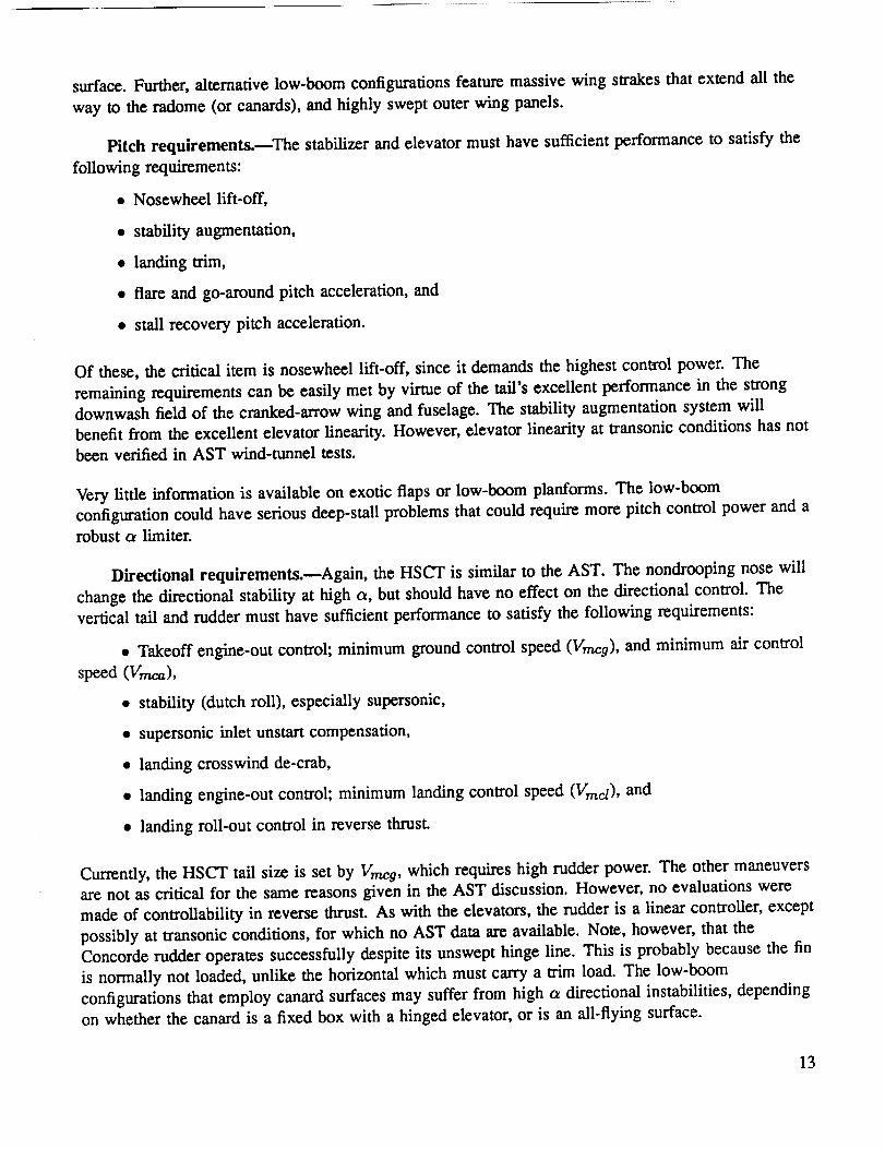
Pitch requirements.--The stabilizer and elevator must have sufficient performance to satisfy the
following requirements:
• Nosewheel lift-off,
• stability augmentation,
• landing trim,
• flare and go-around pitch acceleration, and
• stall recovery pitch acceleration.
Of these, the critical item is nosewheel lift-off, since it demands the highest control power. The
remaining requirements can be easily met by virtue of the tail's excellent performance in the strong
downwash field of the cranked-arrow wing and fuselage. The stability augmentation system will
benefit from the excellent elevator linearity. However, elevator linearity at transonic conditions has notbeen verified in AST wind-tunnel tests.
Very little information is available on exotic flaps or low-boom planforms. The low-boom
configuration could have serious deep-stall problems that could require more pitch control power and a
robust c_ limiter.
Directional requirements.mAgain, the HSCT is similar to the AST. The nondrooping nose will
change the directional stability at high c_, but should have no effect on the directional control. The
vertical tail and rudder must have sufficient performance to satisfy the following requirements:
• Takeoff engine-out control; minimum ground control speed (Vmcg), and minimum air control
speed (Vmca),
• stability (dutch roll), especially supersonic,
• supersonic inlet unstart compensation,
• landing crosswind de-crab,
• landing engine-out control; minimum landing control speed (Vinci), and
• landing roll-out control in reverse thrust.
Currently, the HSCT tail size is set by Vmeg, which requires high rudder power. The other maneuvers
are not as critical for the same reasons given in the AST discussion. However, no evaluations were
made of controllability in reverse thrust. As with the elevators, the rudder is a linear controller, except
possibly at transonic conditions, for which no AST data are available. Note, however, that the
Concorde rudder operates successfully despite its unswept hinge line. This is probably because the fin
is normally not loaded, unlike the horizontal which must carry a trim load. The low-boom
configurations that employ canard surfaces may suffer from high ct directional instabilities, depending
on whether the canard is a fixed box with a hinged elevator, or is an all-flying surface.
13

Lateral requirements.raThe HSCT will be similar to the AS'I', unless vortex high-lift devices
are incorporated. The lateral controls must have sufficient performance to satisfy the following
requirements:
• Takeoff engine-out control Vmca,
• low-speed roll rate,
• stability (spiral mode, roll subsidence),
• supersonic inlet unstart compensation,
• landing crosswind de-crab, and
• landing engine-out control Vine t.
As with the AST, the critical considerations are crosswind de-crab and supersonic unstart
compensation. However, the linearity of the SSDs in supersonic flight and their effectiveness in the
presence of an unstart bow wave were not evaluated in testing of the AST. The low-boom layout will
change the basic lateral stability, but no unique lateral control problems are expected.
Aeroelasticity
The HSCT integrated flight-propulsion control system is expected to include the following capabilities:
(1) stability and control augmentation, (2) structural mode control, (3) flutter suppression, (4) gust load
alleviation, and (5) maneuver load alleviation. Control synthesis, analysis, and test and validation of
these additional capabilities require a combined rigid body and elastic body aeroelastic plant math
model. Each of these capabilities has been demonstrated independently, either in a wind-tunnel test or
during flight test for several aircraft configurations. But, they have not been validated or demonstrated
collectively, i.e., all at the same time on one aircraft, either for the HSCT or any other configuration.
Leading.edge vortex effects.--The HSCT configuration is similar to the AST configuration.
Therefore, the statements made in a previous section concerning the leading-edge vortex are valid for
the HSCT. To reiterate, the leading-edge vortex has little effect on 1-9 flight conditions except for the
lowest flight speeds where _ is high. Current theories of unsteady aerodynamics that neglect the
leading-edge vortex should be adequate to predict the unsteady air loads on the HSCT at these flight
conditions. However, the leading-edge vortex will have an effect on takeoff and landing, initial climb,
2.5 9 maneuvers, and possibly atmospheric gust conditions.
Subsonic cruise is expected to occur at _ near 5 ° and supersonic cruise at lower o_. Therefore, it is
anticipated that the leading-edge vortex will have little effect on 19 flight conditions except for the
lowest flight speeds where o_ is high. However, it will have an effect on takeoff and landing, initial
climb, 2.5 9 maneuvers, and possibly atmospheric gust conditions.
14

Flutter and its suppression.--Because of the similarity of the AST and HSCT, the statements
made in the previous section concerning the AST flutter speed are valid for the HSCT. A large weight
penalty equivalent to 10 percent of the payload may be required to (passively) satisfy the flutter-speed
certification requirement by stiffening the wing. Flutter-speed constraints might require the elimination
of fuel in the outboard wing, resulting in a 5- to 10-percent loss in total fuel capacity. Previous AST
flutter results neglected transonic effects, and axe therefore unconservative. There is a high probability
that the HSCT will be flutter critical, and an active flutter-suppression system should be developed to
avoid the weight penalty and to increase the fuel capacity.
Static aeroelastic considerations.reMaking static aeroelastic corrections to the stability and
control derivatives is important for the HSCT. Its fuselage is much longer than that of the XB-70
discussed previously, i.e., 318 ft as compared to 186 ft. Their fuselage slenderness ratios are similar.
The XB-70 was sized for the high-g maneuvers to meet military requirements, while the HSCT will be
sized by the lower g maneuvers to meet commercial transport requirements resulting in a more flexible
vehicle. The wide variation in vehicle weight because of the HSCT's large fuel weight fraction will
create large variations in the stability and control derivatives during flight.
Structural mode control system.wThe reduction of vibration levels and improvement in the
ride quality of the HSCT's crew and passengers during atmospheric turbulence will be very important,
possibly mission critical. A structural mode control system will most probably be required to achieve
acceptable comfort levels. The HSCT's fuselage length is more than double that of the B-1 discussed
previously, i.e., 318 ft as compared to 146 ft. Their fuselage slenderness ratios are similar. The HSCT
will be more flexible than the B-l, because it will be sized for lower g maneuvers. This flexibility will
aggravate the HSCT vibration levels and ride quality, and will increase the need for a structural mode
control system. The structural mode control system also will help to extend the vehicle fatigue life.
Laminar flow control.wLaminar flow control is planned for HSCT operation at cruise and
possibly upper level climb. Including this effect in the aeroelastic plant math model will reduce the
uncertainty of the model. Laminar flow control reduces viscosity effects on the aerodynamics of the
system. This will make current inviscid analysis methods of unsteady aerodynamics more acceptable.
Gust load alleviation system._The FAA is considering a change in the regulations that will
require designs to accommodate dynamic gust loads significantly higher than today's design load
requirements. Such a change will be very critical to the HSCT, and will probably require a gust load
alleviation system. Even if the regulations are not changed, a gust load alleviation system will still be
desirable to reduce structural weight, extend vehicle fatigue life, and improve the ride quality of the
crew and passengers. This system should work with the structural mode control system.
Spoilers.raThe addition of SSDs and ISSDs along with conventional trailing edge control
surfaces is being considered for the HSCT. The SSDs and ISSDs will be used for roll control and
(possibly) gust and maneuver load alleviation. The unsteady aerodynamic forces caused by spoilers
are generally not well known; even less is known about the unsteady effects of the SSDs and ISSDs.
Aerothermoelasticity._The aerodynamic heating of the HSCT operating supersonically will
cause temperature variations throughout the structure because of heat transfer, and will change the
elastic characteristics of the structure. Elevated temperatures modify material stiffness properties
15

resultingin a softer structure; while thermal loads caused by differential expansions result in a stiffer
structure. These effects will modify the flexible mode shapes and their natural frequencies.
Acoustics
The HSCT is expected to use thrust and flightpath management to control airport and community
noise in a way that is similar to current subsonic aircraft. The propulsion system includes a
variable-cycle engine that will achieve improved acoustic performance at takeoff and improved
propulsive efficiency at cruise. The engine controls will permit this variation in engine cycle. In
addition, the flight guidance control system, e.g., the inertial navigation system, will be an important
system for achieving minimum noise routes. Differences in subsonic aircraft performance, and the
resultant differences in acoustic performance, may require special routing for HSCT. There also may
be a need to optimize the subsonic climb-to-cruise leg (up to Mach 1), so that community noise is
reduced compared to the stage 3 fleet, which will be in existence after the turn of the century.
Airframe-Propulsion Interactions
All airframe-propulsion interactions described in a previous section will be experienced by the HSCT.
In fact, the advanced technologies, strategies, and operating procedures being pursued for economic
viability and environmental acceptability will reinforce them, and introduce additional ones.
Internal inlet-engine-nozzle interactions.--The HSCT will have four under-the-wing mounted
nacelles. Each will contain a variable geometry, mixed compression inlet; a variable cycle engine with
low NOx combustors; and a convergent-divergent, variable area nozzle with noise suppressors. To
improve fuel efficiency and reduce emissions, the propulsion system will operate with reduced stability
margins and at elevated temperatures. Consequently, the sensitivity to internal and external
disturbances will be increased, requiring a more precise and faster acting control system. In addition,
the variable cycle engine concepts being considered, e.g., the fan on blade (FLADE) or turbine bypass
engine CI'BE), have many more effectors, i.e., actuated variables. An example is a bypass system with
its own convergent-divergent nozzle and translating shroud.
Interactions with airframe dynamics.--As discussed in a previous section, the forces and
moments generated by the propulsion system will have a large impact on the flight-control system.
During normal operations, the variable geometry of the propulsion system will require consideration in
the design of the flight-control system. Likewise, the propulsion control system will require
knowledge of the flight-control system. The interactions will be even greater for the HSCT; unlike the
YF-12/SR-71, the XB-70, and the Concorde, the HSCT is designed to be longitudinally unstable. By
purposely making the aircraft unstable, the control system must be faster and stronger, or a reduction
in vehicle performance, e.g., ride and handling qualities or trajectory tracking, must be accepted. The
key issue here is the interaction and coupling of both systems. An accurate math model including the
interactions needs to be incorporated into the control synthesis process during the initial and on-goingdesign phases of the HSCT.
Abnormal operation (e.g., unstart) may cause even more severe problems for aircraft control. Sensing
and accounting for these abnormal and emergency situations place added requirements on the control
16

system. Safe control of flight and preventing the aircraft from entering dangerous flight regimes are
some issues in integrated flight-propulsion control system design.
Flightpath Management
All control augmentation issues discussed in a previous secdon for the AST will apply to the HSCT
because of the similarities in configuration of the two aircraft. There arc several issues that were not
considered for the AST system studies that will be important to HSCT. These issues include flightpath
management concepts (control of landing paths and takeoff flight profiles), fuel management (to
control the e.g.), and the impact of structural materials (especially composites) on the controllability of
the aircraft. The next paragraphs discuss the control issues unique to the HSCT as a result of
configuration differences between it and the AST, and the integrated design approach to developing its
flight-control systems.
Fiightpath management concepts..--Control of the terminal area flightpaths of an HSCT will
require special considerations. The HSCT traffic must be mixed with other subsonic aircraft. This
mixing includes integrating HSCT's transition from supersonic routes over water to subsonic legs over
land with all other traffic. Though the HSCT landing speeds will bc comparable to subsonic aircraft
(140-150 kn), special consideration of routes is necessary to satisfy noise abatement and for
maintaining adequate aircraft spacing. Whatever the guidance concepts employed (ILS, MLS, GPS),
the routes stored in the airborne computer may be unique to HSCT. For example, four-dimension
guidance may be necessary to integrate the less-frequent HSCTs into the more frequent subsonic
traffic. In addition, the HSCT, with its synthetic vision capability, will be capable of landing in very
low or no visibility conditions. This landing capability will affect the lateral and vertical flightpaths
for HSCT and must be considered in the design of the on-board landing guidance system.
Another unique flightpath management concept for HSCT is the modulation of flaps, slats, and engine
control during takeoff. Design considerations may dictate a vertical flight profile that can bc achieved
only by implementing new techniques during takeoff. Design considerations, safety, and certification
arc some of the issues of flightpath management for departures.
Fuel management systems.reFuel management to control the c.g. location will be a full-time
system on the HSCT. There are several impacts of fuel management on the flight control system.
Control of the e.g. will help in maintaining the desired stability of the aircraft as the fuel is depleted.
Moving fuel to other locations will also cause the strucawal properties to change. The weight and
inertia (and therefor_ damping and frequency) of the structure will change with the amount of fuel.
The control system must be designed accordingly. Drastic shifts will require an adaptive scheme with
multiple sensors, while minor shifts can be handled with robust control concepts. There are limits on
how fast the fuel can be wansferred, and this rate will affect the frequency of the system to be
controlled. Fuel sloshing also may be an issue, but probably not a major one if there are many
(10-20) separate tanks and adequate baffling to reduce fuel movement.
Since a large percent of the total takeoff weight is fuel, there will be a big difference in the
characteristics of the aircraft between takeoff and landing. The control system must account for this
change, and may require gain scheduling or other techniques to cope with changes in rigid body and
17

structural dynamic characteristics. Because the weight change is slow, there is no major control issue;
however, this condition needs to be considered during the control system design.
Control system-composites interaction.--Composite materials will be used on the HSCT in
secondary structures (such as control surfaces) and in the primary structure. Inclusion of a large
amount of composites will change the stiffness and natural frequency of the structure. The flight
control system must control the aircraft flexible modes, whose frequencies could be significantly
different from those of the AST. Adequate math modeling of the structural dynamics for an aircraft
system with composites is required, and their impact on the control laws must be considered in the
design phase.
Control Design Technology and Methodology Issues
In this section the technologies and methodologies required for designing and analyzing the control
systems for the HSCT are discussed. Each required technology and methodology is examined to
identify which is sufficient and which needs further research and development for a successful HSCT.
The shortcomings are summarized, and the development plans, which are presented in a later section,
are briefly discussed. The organization is the same as in previous sections.
Aerodynamic Stability and Control
Since the HSCT's shape is so similar to the AST's, there is a wealth of wind-tunnel test data for all
but transonic conditions. Various NASA cranked-arrow configurations have been tested as well,
providing more information on canard and twin fin control layouts. The major uncertainties relate to
exotic high-lift systems and low-boom planforms.
The state of the art in computational fluid dynamics (CFD) is such that we can predict many
aerodynamic stability and control terms in the absence of separation. Panel methods are useful for
subsonic conditions, and are not confined to simple configurations. In fact, we can evaluate the
complete wing-body-nacelle and empennage with flaps including power effects. The panel methods
are accurate up to the onset of significant trailing-edge separation, and they are valid all the way up to
stall when the wing is leading-edge stall critical. The effect of leading edge vortices and flaps can be
modeled by the Carlson code, which is based on linear theory with empirical vortex modeling.
Transonic full potential methods and Euler solvers are valid up to normal Mach numbers of 1.4+ with
no separation, but the geometry must often be simplified because of limitations in the computational
grid. The AIRPLANE Euler code promises to overcome these grid limitations by using an
unstructured tetrahedral grid. Thin-layer Navier-Stokes codes can model separation, but are generally
limited to simple geometries.
The aerodynamic stability characteristics of the HSCT are fairly well understood. The airplane will be
unstable in pitch at low speed over the operational c_ range. Yet, the level of low-speed instability fails
well within the time-to-double-amplitude experience that the industry has with high-performance
fighters; 1 see for the HSCT in comparison with 0.2 sec for modem fighters. The HSCT will be
statically stable in the transonic and supersonic ranges.
18

Directionally, theHSCT is neutrally stable at very high a, and slightly unstable at high Mach number.
Again the level of instability is well within industry experience, if the control effector (i.e., rudder) is
linear and has sufficient authority.
The HSCT rudder and elevator control surfaces are surprisingly well behaved control effectors. A
typical subsonic transport suffers from a variety of nonlinear control issues related to shock-induced
separation or stalled wing wakes engulfing the tail. This is not so for the HSCT, which has a wing that
does not truly stall by virtue of its high leading-edge sweep, and tail surfaces that do not have strong
normal shocks at trim. The transonic performance of the elevator still needs to be validated. However,
this is not a critical technology issue, since any problems can be easily addressed through hinge-line
sweep changes.
No test data exist for HSCT-like configurations in reverse thrust. The concern is loss of directional
control during landing roll.out or a rejected takeoff while on a wet or icy runway. Fortunately, the
cascade-type reversers envisioned for the HSCT allow efflux tailoring to limit tail interference.
Consequently, this is not seen as a critical technology issue but a product development issue.
The spoilers and SSDs are not as well behaved as the elevator and rudder. The NASA/DAC-AST
wind-tunnel tests revealed some unusual subsonic spoiler characteristics. The spoilers performed
poorly at low flap settings, and the SSDs were fully reversed. The latter is not a concern, since they
are not intended to operate at these speeds. However, little data exist for the SSDs supersonically,
especially in the presence of an unstart bow wave. Wind-tunnel evaluation is needed to determine if
the SSDs are adequate for unstart roll compensation, and if not, to develop an option such as
asymmetric elevator or relocated SSDs. This is a borderline issue that is probably not critical for
technology readiness, since it would not have a significant configuration impact.
Significant questions exist regarding advanced high-lift systems. If some form of vortex trapping is
used (beyond the leading-edge vortex flows where we have experience), then we need more low-speed
wind-tunnel tests for technology readiness. This information will be needed 2 years prior to
engineering ATP if such devices are desired for the HSCT. The key issues will be
• Lateral control effectiveness in the presence of these devices;
• transitional lift, moment, and drag, during deployment;
• vortex stability in the presence of pitch, roll, and yaw rates; and
• vortex trajectories relative to the tail surfaces.
The low-boom planforms are so different from the AST that a major wind-tunnel test program would
need to be completed two years prior to engineering ATP. The testing required for stability and
control analysis is most critical in the low-speed regime, and should at least cover the following:
• Basic pitch and yaw characteristics, at various flaps,
• pitch and directional trim and control effectiveness, and
19

• deep-stallcharacteristics.
In summary, previous SST studiesand testdata have eliminatedmost of the criticaltechnology
questionsfor HSCT stabilityand control.However, ifexotichigh-liftsystems or low-boom planforms
arc selected,we willneed to begin a major wind-tunneltestprogram.
Aeroelasticity
In thissection,the technologiesand methods used foraeroclasticanalysisarc examined. First,a brief
descriptionof the stateof the artisgiven.Next, the shortcomings of the technologiesand methods are
identified.The shortcomings arc summarized, and the development plan for each isbrieflydiscussed.
State of the art.--The current state of the technology in aeroelastic analysis includes separate
unsteady aerodynamic and structural analyses, and a splining procedure to permit interaction between
them to perform the aeroelastic analysis.
The unsteady aerodynamic analysis works like this: traditional lifting surface theories determine the
frequency dependent magnitude and phase of the aerodynamic force over a lifting surface element
caused by motion of another element. These forces are generally weighted to match wind-tunnel data
at the steady-state condition. More modern CFD methods perform numerical integration to solve the
governing equations in time; CFD methods are usually more computation intensive compared to lifting
surface analysis, and are not widely used for production work.
In a structural aerodynamic analysis, generalized coordinates consisting of a reduced set of flexible,
natural mode shapes are derived from simple beam stick models or more complex finite element
models. The analytically derived mode shapes, natural frequencies, and damping are validated through
full-scale ground vibration testing. Modern finite element methods for structural analysis are also
available; these permit application of time varying loads to a deforming structure.
Aerodynamic data are passed to the structural analysis module by a splining procedure. This allows
the models for the aerodynamic and structural analyses to be developed based on their individual
algorithm requirements.
Structural and unsteady aerodynamic analyses are deemed adequate for analyzing the HSCT for most
of the normal operating conditions. For structural analyses, complex finite element models can
accurately determine natural frequencies and mode shapes for a given fuel and payload distribution.
MSC/NASTRAN can determine the effect of a prescribed temperature distribution by solving the heat
transfer problem to obtain internal structural temperatures. It can then solve the normal mode problem
while accounting for material stiffness variation with temperature and differential stiffness caused bythermal loads.
For unsteady aerodynamic analyses, lifting surface theory with weighting is expected to be adequate
for subsonic flow, using the doublet-lattice method (DLM), and supersonic flow, using the harmonic
gradient method (ZONA). For further refinement and to estimate the importance of transonic effects,
the computational aeroelasticity program - transonic small disturbance CFD code is well suited for the
HSCT configuration.
20

Shortcomings of the state of the art.raThe shortcomings of the state of the art for aeroelastic
analysis of the HSCT are confined to three topics. Traditional responsibility for an aircraft's rigid
body behavior resideswith a stabilityand controlgroup, while responsibilityfor flexiblebody
behavior resideswith a dynamics group. The rigidbody portionof the flexiblebody model attemptsto
predictthe stabilityand controlspecifiedrigidbody behavior.The methodology to blend adequately
the rigidbody and flexiblebody models togetherintoone unifiedacroclasticplantmath model needs
improvement.
Many potential aeroelastic systems that might be used on the HSCT have been demonstrated
individually in wind-runnel or flight tests, but not collectively. A free-flying, flexible, wind-tunnel
model, flight test drone, or flying prototype of the HSCT configuration combining the stability and
control augmentation, flutter suppression, structural mode control, gust load alleviation, and maneuver
load alleviation systems must be used to verify the complete system.
Very littlesteady and unsteady aerodynamic dam and analysiscapabilityarc availablefor spoilers,
SSDs, and ISSDs. Wind-tunnel testsand enhanced analysiscapabilitiesarc needed toobtain this
information.In addition,the roleof viscous effectsmust be assessed in transonicflow conditions
using more advanced CFD methods.
Another topicof concern, but not necessarilya shortcoming of the stateof the art,isthe
undcrutilizationof emerging methodology. Recent advances in multidisciplinaryoptimization
techniquespermit the optimizationof acroclasticsystems,includingthe controlsystem, to further
enhance the overallvehicledesign.
Four issues.--Four topicsmake up the criticalaeroclastictechnology issuesassociatedwith
acroclasticity:(I) separaterigidand flexible-bodyanalyticalmodels, (2) undemonstratexiintegrated
controlof unstable,flexibleaircraft,(3)lack of unsteady acro data for SSDs, and (4) undcrutilization
of multidisciplinaryoptimization.
Plan with tasks and schedule.--Tbe first critical aeroelasticity issue to resolve for the HSCT
(separaterigidand flexible-bodyanalyticalmodels) willrequiretwo to threeman-years of industry
effortto complete the following tasks:(1) identifymethods, (2) evaluatemethods, (3)implement best
method, and (4) validate.This issuemust be resolved by the time HSCT hi-fidelitymodeling starts,
which isassumed to be one year priorto engineeringATP.
To demonstrate integrated control of unstable, flexible aircraft will require a wind-tunnel test or flight
test, either a drone or preferably a prototype HSCT. Because of the expense, this task will not be
initiated until after engineering ATP, but it should be completed prior to program ATP to evaluate the
alternatives if shortcomings are identified.
To resolvethe thirdcriticalacroclasticityissue(lackof unsteady aerodatafor SSDs) willrequire
6 man-years of NASA and industryeffortto complete the following tasks:(I)add SSD and ISSD
capabilityto CFD, (2) wind-tunnel testing,and (3)con'elateCFD with testdata.This issueshould be
resolved by the startof HSCT hi-fidelitymodeling, assumed to be one year priorto engineeringATP.
21

To resolve the fourth critical aeroelasticity issue (underutilization of multidisciplinary optimization)
will require three to 4 man-years of industry effort to complete the following tasks: (1) review
existing methodology, (2) develop/refine methodology, and (3) demonstrate methodology. This issue
should be resolved by engineering ATP to impact the HSCT.
Acoustics
McDonnell Douglas has developed an all-engine flightpath community noise (AEFPNOIS) computer
program that estimates the noise levels at the airport and community monitors and takeoff and landing
performance for a given initial configuration and operational procedure of the aircraft. This PC-based
program has been provided to certain airlines for preflight planning guidance.
It would be desirable to extend AEFPNOIS to a tool that would provide optimal takeoff and landing
procedures for the lowest community noise exposure for any given set of airport restrictions and noise
monitor locations. Such operational optimization would include the following:
1. Takeoff and landing weight,
2. Takeoff and landing flap settings,
3. Flap retraction during second-segment climb,
4. Takeoff and landing speed,
5. Initial cutback altitude (optimized using inertial navigation system and noise-power-distance
database),
6. Cutback power management, and
7. Enroute (far-out monitor) climb.
As partof crew planning,the ambient ground conditions,i.e.,maximum takeoffweight,temperature,
and headwind component, could be enteredin a program containinga database of airportspecific
requirements and noise monitor locationsOimits).The noise model would provide an alternative
noise-abatementprocedure in additionto expected community noise levels,which could be furnished
to an airportnoise abatement officefor continued good publicrelationsfor the particularcarrier.
As part of preliminary aircraft design, especially for HSCT applications, the model could be used to
optimize a takeoff procedure for proposed acceptance in compliance with current and future noise
certification requirements. If such a procedure was judged safe for flight and included in the aircraft
flight management system for "routine" takeoff operations, the FAA, JAA, and ICAO might be more
willing to accept such noise-related automated operational procedures.
Airframe-Propulsion Interactions
This section discusses the technologies and methods required for designing control systems for the
propulsion system and for integrating the flight and propulsion systems. Four levels of control can be
considered. The first, or outermost, level specifies the optimum flightpath. The second determines the
22

optimum aircraft attitude along the trajectory. The third integrates all the aerodynamic and propulsive
forces and moments required to trim the aircraft attitude. The fourth level performs stability
augmentation, disturbance rejection, and noise attenuation.
Inlet-engine-nozzle integrated control--Because of the high level of interaction, integrating the
control of the inlet, engine, and nozzle at the third level, i.e., trim and stability, can significantly
improve the overall performance. Throughout the 1970's, much work was performed in the area of
improving the shock position stability of mixed compression, axisymmetric inlets by way of active
control of bleed and bypass systems (ref. 14-22). This work was directed primarily at the
YF-12/SR-71, and dealt with only the inlet and was successful in developing a system that virtually
eliminated unstarts and reduced inlet stability margins. Additional work was performed on integrated
inlet-engine control, but the concepts were not flight tested (refs. 23 and 24).
For the HSCT, it is necessary to perform research to identify the performance characteristics of the
inlets being considered that will identify the inlet stability margins required to achieve the desired
performance. This research must also consider the control system hardware, e.g., sensors, actuators,
processors, and performance requirements. Sufficient data and inlet math models exist for an
analytical study to give results accurate enough for preliminary purposes. The research should be
performed as part of the inlet selection process.
Since the mid-1980's, the NASA Dryden Flight Research Facility has sponsored the highly integrated
digital electronic control (HIDEC) flight research program (refs. 39--41). Two engine control modes
and two systems that integrated the inlet, engine, and nozzle were developed. The first engine control
mode is called the adaptive engine control system mode, and trades stall margin for thrust by
increasing engine pressure ratio at constant airflow when inlet distortion is low; equivalently, fuel flow
can be reduced by keeping thrust constant and reducing the throttle setting as EPR increases.
The second engine control mode is called the extended engine life mode, and increases engine life by
reducing turbine temperature at constant thrust by increasing engine pressure ratio while decreasing
airflow. The first inlet integration system trims the inlet ramps to improve performance. The second
inlet integration system is called performance seeking control, and it contains a Kalman filter that
estimates the values of certain engine performance parameters and updates a built-in engine model to
match the actual engine (refs. 42 and 43). As this is done the control algorithm optimizes the
combined propulsion-airframe system performance.
All the HIDEC modes just described did not improve performance as much as predicted. The
consequences of not matching predicted levels for a research program are not severe. However, for a
production program the consequences are very costly. Therefore, the accuracy of propulsion system
performance prediction models must be improved. This work must be completed in time for the
advanced modes to be developed to a point to allow performance guarantees to be given to airlines
when authority to offer (ATO) is given. Depending on the airline orders, ATO precedes program
authority to proceed (ATP) by about a year.
Before the development of advanced modes, e.g., performance seeking control, the benefits must be
identified, and weighed against the costs and risks. This analysis will probably have to be performed
with existing performance models since the improvements to the prediction models are not expected
23

beforedevelopmentbegins.The benefits, costs, and risks need to be identified about three years
before engineering ATP to allow time for development of the advanced modes.
The robustness of the HIDEC advanced control modes is unknown. The synthesis and analysis did not
include a measure of stability margin. It is necessary for safety and risk reduction to have robustness.
It is best to be able to design it into the system, while existing systems also need to be analyzed. A
significant effort will have to be made to develop robust adaptive control synthesis and analysis tools
and methods. The best case scenario is to have the synthesis tools available for the development of the
advanced modes. The minimum requirement is to have the analysis tools available toward the end ofdevelopment.
Integrated flight-propulsion control.---One important issue for HSCT is the implementation of
an integrated flight-propulsion design. The architecture for an integrated system definition will require
inputs from several engineering technologies. These inputs must be interfaced in such a manner that
the control system design can be formulated and implemented successfully. The major issue in this
undertaking is the ability of each member of the design team to contribute to the project goal. This
goal is to formulate a control system that accounts for as many interactions as possible. This
formulation must take place early-on in the design process to be viable. Architecture definition should
be developed in a two year period beginning in early 1992. Preliminary data can facilitate the
architecture definition, ff detailed math models are not available at this time. A preliminary
architecture definition should be complete by the end of 1993.
Control Augmentation and Flightpath Management
Controlling unstable, flexible aircraft.---Controlling an unstable aircraft through augmentation
will require extending present techniques to satisfy constrained optimization problems. These
constraints, often conflicting, present problems to the system designer when an integrated design is to
be achieved. After the component systems have been modelled with sufficient accuracy, the tools to
synthesize an integrated control system must be chosen and used to complete the design. This selectionis the major issue in designing controls for an unstable, flexible aircraft. Because of the critical nature
of this system development, a three and one half year effort will be required, beginning as soon as the
math models are available, but not later than mid-1992 to meet the engineering ATP milestone.
Fiightpath management.nNoise abatement and enhanced operating procedures will be a
requirement of the flightpath management system. The constraints for both takeoff and landing
profiles must be clearly defined to formulate the controls problem. The requirements issue here is to
determine what flightpath will be required for the HSCT. The synthesis-analysis issue is to solve the
problem in a manner that satisfies all the constraints imposed on the system. Safety of flight,
certification, ATC procedures, and man-machine interfaces are all issues that will drive the flightpathmanagement problem.
The noise abatement task will be addressed by identifying the noise criteria and applying it to the
HSCT. The main milestone of this task is the establishment of the requirements. The operating
procedures task will encompass establishment of the takeoff and landing constraints, which will then
lead to synthesizing the optimal trajectories for the flightpath management system. Both these tasks
can be in parallel, and should take about one and a half years. These tasks should start at the
24

beginning of 1992, but this timing is probably not critical. However, if serious problems in
implementing these management concepts arc encountered, there must be time to complete the
synthesis, analysis, and validation tasks. The final verification phase of the flightpath management
system should bc complete _ years after start of the requirements phase.
Fuel managemenL---Center of gravity control and control of the aircraft to account for different
characteristics bctwe._n takeoff and landing can be parallel efforts. A one and a half year schedule
seems appropriate for these tasks, where the milestone of having the control architecture developed
should bc at the end of 1994.
PRIORITIZATION OF THE DESIGN AND ANALYSIS ISSUES
Seventeen critical issues were identified in the previous section. Many of them are interrelated, and
some of them depend on the results of the research that ne,e,ds to be performed to address other issues.
For example, if studies indicate that using advanced control modes significantly improves
performance, then it is necessary to develop the synthesis and analysis tools for robust advanced
control modes. All of the issues axe listed in the following:
• Define advanced high-lift system stability and control characteristics.
• Define low-boom planform stability and control characteristics.
• Develop a unified rigid and flexible body analytical model.
• Demonstrate integrated control of unstable, flexible aircraft.
• Generate unsteady aero data for SSDs.
• Use multidisciplinary optimization.
• Extend noise prediction program to provide optimal procedures.
• Define the benefits and costs of reduced inlet stability margins.
• Develop robust advanced control synthesis and analysis tools.
• Define benefits and costs of advanced control modes.
• Define the reduced inlet stability control system architecture.
• Improve propulsion system performance prediction models.
• Develop constrained optimization synthesis and analysis tools.
• Define the takeoff and landing profile consu'aints.
• Develop aircraft controls for large fuel fraction variation.
• Develop the integrated flight-propulsion control system architecture.
• Define large transport flying quality criteria.
25

A quantifiableprioritization of the issues was not undertaken for this study. There are several reasons
for this. First, the HSCT is not defined adequately to perform the studies required to generate the
performance data for evaluation. Second, even if the HSCT were adequately defined, the time required
to complete such studies is far beyond the period of this study. Finally, it was decided that numerical
results from the application of one technology on another aircraft or predicted in a research program
could not be considered valid and accurate for the HSCT.
Given that a quantifiable prioritization was not undertaken, the obvious alternative is a qualitative
prioritization. Three priority levels were defined: mandatory, highly beneficial, and desirable. A
three-stage process was used to rank the issues. First, the study team jointly considered to which
category each issue belonged. Once all the issues were assigned to one of the three categories, they
were ranked within their category. Finally, the results were reviewed by the HSCT program office.
The highest priority level is mandatory. The issues in this category are those that must be addressed
for the HSCT to be viable, i.e., issues related to HSCT control systems that will be required to
compensate for vehicle characteristics. An example is stability augmentation and flexible mode
control. The following are the mandatory issues in order of importance:
1. Demonstrate integrated control of unstable, flexible aircraft.
2. Develop the integrated flight/propulsion control system architecture.
3. Define large transport flying quality criteria.
4. Generate unsteady aero data for SSDs.
5. Define the takeoff and landing profile constraints.
The second priority level is highly beneficial. Issues assigned to this category are those related to
significant performance improvements, i.e., fuel efficiency, drag reduction, weight reduction, etc.,
and/or risk reduction, i.e., development costs, schedule impacts, etc. The highly beneficial issues are
listed in the following:
1. Define the benefits and costs of reduced inlet stability margins.
2. Develop a unified rigid and flexible body analytical model.
3. Define benefits and costs of advanced control modes.
4. Develop robust advanced control synthesis and analysis tools.
5. Define the reduced inlet stability control system architecture.
6. Develop constrained optimization synthesis and analysis tools.
7. Develop aircraft controls for large fuel fraction variation.
8. Improve propulsion system performance prediction models.
9. Define advanced high-lift system stability and control characteristics.
26

I0. Define low-boom planform stabilityand controlcharacteristics.
The third, and lowest, priority level is desirable. These issues were deemed marginally beneficial or
the current technology level is immature and requires a good deal of development. Two issues were
categorizedas desirable.
1. Use multidisciplinary optimization.
2. Extend noise prediction program to provide optimal procedures.
TECHNOLOGY DEVELOPMENT PLANS
The technology development plans for all the critical issues are presented as figures 20-36. Each
figure identifies an issue, briefly explains the issue, states the impact of not addressing the issue, and
presents the tasks and schedule for developing the required technology.
CONCLUSION
The critical control system design and analysis issues for the HSCT were identified and ranked. A
technology development plan for each issue was presented.
Many issues relate to items that require long lead times in the development of control systems, and
therefore need to be considered immediately or the 2005 service date will not be met. Most pressing is
the establishment of the fundamental requirements. Trade studies need to be performed to identify the
benefits of applying advanced technologies, to determine if automatic controls will be required to meet
certification or minimum performance requirements, and to define the costs.
The greatest challenge to HSCT control designers will be to integrate successfully the controls to meet
the many, and sometimes conflicting, requirements. Many technologies required have been applied
individually, but the HSCT will require all of them to be applied simultaneously.
It does not appear that any revolutionary new technologies or methodologies are required for a viable
HSCT. However, significant shortcomings of the existing technologies and methodologies do exist that
need to be addressed. Failure to do so will result in a very high risk development program and slip the
service date by probably several years. Again, the long lead items must be addressed by the end of
1993 to 1994. This is required to ensure enough time for the development of the necessary
technologies and methods to accurately predict HSCT performance to guarantee airline profitability,
before committing to full-scale development.
REFERENCES
1. Douglas Aircraft Company, Study of High-Speed Civil Transports, NASA CR-4235, 1989.
27

2. Domack, Christopher S., "Results of a Preliminary Investigation of Inlet Unstart on a High-Speed
Civil Transport Concept," presented at the Propulsion/Airframe Integration Meeting, NASALangley Research Center, December l l, 1990.
3. Radkey, R.L, H.R. Welge, and J.E. Felix, Aerodynamic Characteristics of a Mach 2.2 Advanced
Supersonic Cruise Aircraft Configuration at Mach Numbers from 0.5 to 2.4, NASA CR-145094,1977.
4. Douglas Aircraft Company, Technology Application Study of a Supersonic Cruise Vehicle, NASACR- 159276, 1980.
5. Douglas Aircraft Company, Technology Application Studies for Supersonic Cruise Vehicles, NASA
CR-144925, vol. 1, 1975.
6. Wykes, J.H. and R.E. Lawrence, "Aerothermoclasticity: Its Impact on Stability and Control of
Winged Aerospace Vehicles," AIAA J. Aircraft, vol. 2, no. 6, Nov.-Dex:., 1965.
.
.
.
10.
11.
16.
17.
Wykes, J.H., C.J. Borland, M.J. Klepl, and C.J. MacMiller, Design and Development of a
Structural Mode Control System, NASA CR-143846, 1977.
Wykes, J.H., T.R. Byar, C.J. MacMiller, and D.C. Greek, Analysis and Tests of the B-1 Aircraft
Structural Mode Control System, NASA CR-144887, 1980.
Coleman, HJ., "Concorde Tour Adds to Operations Data," Aviation Week & Space Technology,
Aug. 7, 1972, pp. 31-33.
Berry, Donald T. and Glenn B. Gilyard, "Airframe/Propulsion System Interactions - An Important
Factor in Supersonic Aircraft Flight Control," AIAA 73-831, 1973.
Schweikhard, W'flliam G. and Donald T. Berry, "Cooperative Airframe/Propulsion Control forSupersonic Cruise Aircraft," SAE-740478, 1974.
Young, P., "Propulsion Controls on the Concorde," J. Roy. Aeronaut. Soc., vol. 70, Sept. 1966.
Chun, K.S., and R.H. Burr, "A Control System Concept for an Axisymmetric Supersonic Inlet," J.
Aircraft, vol. 6, no. 4, July-Aug. 1969.
Inlet Stability Workshop, NASA Lewis Research Center, Nov. 27, 1990.
Fukuda, Michael K., Warren G. Hingst, and Eli Reshotko, Control of Shock Wave - Boundary
Layer Interactions by Bleed in Supersonic Mixed Compression Inlets, NASA CR-2595, 1975.
Sanders, Bobby W. and Glenn A. Mitchell, Throat-Bypass Bleed System for Increasing the Stable
Airflow Range of a Mach 2.50 Axisymmetric Inlet with 40-Percent Internal Contraction, NASATM-X-2779, 1973.
Mitchell, Glenn A. and Bobby W. Sanders, Pressure-Activated Stability-Bypass-Control Valves to
Increase the Stable Airflow Range of a Mach 2.50 Inlet with 40-Percent Internal Contraction,
NASA TM-X-2972, 1974.
28

18. Sanders, Bobby W., Dynamic Response of a Mach 2.5 Axisymmetric Inlet and Turbojet Engine
With a Poppet-Valve Controlled Inlet-Stability Bypass System When Subjected to Internal and
External Airflow Disturbances, NASA TP-1531, 1980.
19. Sanders, Bobby W., Turbojet-Exhaust-Nozzle Secondary-Airflow Pumping as an Exit Control of an
Inlet-Stability Bypass System for a Mach 2.5 Axisymmetric Mixed-Compression Inlet, NASA
TP- 1532, 1980.
20. Nciner, Cmorg¢ H., Gary L Cole, and Dale J. Arpasi, Digital-Computer Normal-Shock-Position
and Restart Control of a Mach 2.5 Axisynvnetric Mixed-Compression Inlet, NASA TN-D-6880,
1972.
21. Lehtinen, Bruce and John R. Zeller, Optimal Control of Supersonic Inlets to Minimize Unstarts,
NASA TN-D-6408, 1971.
22. Seidel, Robert C. and Bruce Lehtinen, Control System Design Using Frequency Domain Models
and Parameter Optimization, With Application to Supersonic Inlet Controls, NASA TM-X-3108,
1974.
23. Cole, Gary L., George H. Neiner, and Robert E. Wallhagen, Coupled Supersonic Inlet-Engine
Control Using Overboard Bypass Doors and Engine Speed to Control Normal Shock Position,
NASA TN-D-6019, 1970.
24. Paulovich, Francis J., George H. Neiner, and Ralph E. Hagedorn, A Supersonic Inlet-Engine
Control Using Engine Speed as a Primary Variable for Controlling Normal Shock Position, NASA
TN-D-6021, 1971.
25. Michael, Gerald J. and Florence A. Farrar, "Development of Optimal Control Modes for Advanced
Technology Propulsion Systems," Office of Naval Research Report N911620-2, Mar. 1972.
26. Hiller, Kirby W. and Danial I. Drain, Control of Propulsion Systems for Supersonic Cruise Aircraft,
NASA CP-001, Proceedings of the SCAR Conference, Langley Research Center, Nov. 9-12, 1976.
27. Albers, James A. and Frank V. Olinger, YF-12 Propulsion Research Program and Results, NASA
CP-001, Proceedings of the SCAR Conference, Langley Research Center, Nov. 9--12, 1976.
28. Wolowicz, Chester H., Larry W. Strutz, Glenn B. Gilyard, and Neil W. Matheny, Preliminary
Flight Evaluation of the Stability and Control Derivatives and Dynamic Characteristics of the
Unaugmented XB-70-1 Airplane Including Comparisons with Predictions, NASA TN-D-4578,
1966.
29. Wolowicz, Chester H. and Roxanah B. Yancey, Summary of Stability and Control Characteristics
of the XB-70 Airplane, NASA TM-X-2933, 1973.
30. North American Aviation, Inc., Flight Control Systems-XB-70 Air Vehicles, Contract
AF33(600)-42058," NA-60-2, rev. 5, July 1962.
31. Reukauf, Paul J. and Frank W., Burcham, Jr., Propulsion System�Flight Control Integration for
Supersonic Aircraft, NASA CP-001, Proceedings of the SCAR Conference, Langley Research
Center, Nov. 9-12, 1976.
29

32. Berry, Donald T., Donald L. Mallick, and Glenn B. Gilyard, Handling Qualities Aspects of NASA
YF-12 Flight Experience, NASA CP-001, Proceedings of the SCAR Conference, Langley
Research Center, Nov. 9-12, 1976.
33. Powers, Bruce G., Phugoid Characteristics of a YF-12 Airplane With Variable-Geometry Inlets
Obtained in Flight Tests at a Mach Number of 2.9, NASA TP-1107, 1977.
34. Gilyard, Glenn B., Donald T. Berry, and Daumants Belte, Analysis of a Lateral-Directional
Airframe Propulsion System Interaction, NASA TM-X-2829, 1973.
35. Gilyard, Glenn B. and John J. Burken, Development and Flight Test Results of an Autothrottle
Control System at Mach 3 Cruise, NASA TP-1621, 1980.
36. Burcham, Frank W., Jr. and Peter G. Batterton, Flight Experience with a Digital Integrated
Propulsion Control System on an F-111E Airplane, AIAA-76-653, 1976.
37. Douglas Aircraft Co., Technology Application Study of a Supersonic Cruise Vehicle, NASA
CR- 159034, 1979.
38. Douglas Aircraft Co., Technology Study for Advanced Supersonic Cruise Vehicles, NASA
CR-165723, 1981.
39. Yonke, W.A., L.A. Ten'ell, and L.P. Meyers, "Integrated Flight/Propulsion Control: Adaptive
Engine Control System Mode," AIAA-85-1425, 1985.
40. Landy, R.J., W.A. Yonke, and J.E Stewart, "Development of HIDEC Adaptive Engine Control
Systems," ASME Journal of Engineering for Gas Turbines and Power, vol. 109, Apr. 1987.
41. Smith, R.H., J.D. Chisholm, and J.E Stewart, "Optimizing Aircraft Performance with Adaptive,
Integrated Flight/Propulsion Control," ASME Paper 90-GT-252, July 1990.
42. Berg, D.E, J.A. Swan, S. Ahdlbatlar, P.D. Shaw, and E.J. Tich, "Performance Seeking Control,"
AFWAL-TR-88-2067, vol. 1, Oct. 12, 1989.
43. Luppold, R.H., J.R. Roman, G.W. Gallops, and L.J. Ker, "Estimating In-Flight Engine
Performance Variations Using Kalman Filter Concepts," AIAA-89-2584, July 1989.
30

RIGID AIRPLANETAIL.OFF LIFT
COEFFICIENT
(Ct.,roI
SYM RUN AF IOEGi 05
Figure 1.
NOTE LEADING EDGE FLAPS CLEAN
I I !020 0 10 0 -0 10
TAIL.OFF PITCHING MOMENT COEFFICIENT ICIV_TOcj4 I
Advanced supersonic transport tail-off pitching moment coefficient for various flap deflections.
31

RIGID AIRPLANE
TAIL,OFF LIFT
COEFFICIENT
|CL,ro)
SVM RUN _'F (OEG)
(_ 785 0
0 gll 20
80t 30
NOTE LEADING EDGE FLAPS DEFLECTION (RI
Figure 2.
deflected.
I I
0 20 0 10 0 -0 tO
TAIL-OFF PITCHING MOMENT COEFFICIENT ¢/4)ICM,r o
Advanced supersonic transport tail-off pitching moment coefficient with the leading edge
32

RIGID AIRPLANE
SYM RUN _F (OEG) _M (DEG)
Figure 3.
NOTE: CLEAN LEADING EDGE
I I o0.3O 0.2O 0 10
PITCHING MOMENT COEFFICIENT ICk_ c/4 I
Advanced supersonic transport tail-on pitching moment for several tail incidence settings.
33

.%
LIFT
COE FF ;CIE NT
(CLTo)
RIGID AIRPLANE
NOTE LEADING EDGE FLAPS DEFLECTED (RI
_F " 30OEG
rA+L.OFF
Figure 4.
downwash.
I
0 I0 0 0 I0
PITCHING MOMENT COEFFICIENT |CMT O C141
Advanced supersonic transport tail-on pitching moment characteristics used to calculate
34

RIGID AIRPLANE
NOTE: 6LE " R, 6 F " 30DEG (LOWSPEED)
0.04 --
YAWING MOMENT
COEFFICIENT, Cn . --
--20 -15
__ -0.02 -
Figur_ 5.
-0.04 --
IOF - 13DEG_
I - I I I
15 20
SIDESLIP ANGLE,
GI
TAIL4Z)FF
Esdmatexl yawing moment coefficient versus sideslip angle.
35

RIGID AIRPLANE
NOTE: _LE = R'6F = 30 DEG (LOW SPEED)
0.04- 1% _ 17pEG ]
_YAWING MOMENT
OEFFICIENT, Cn
I I I
-20 --15 -10 / -5i
Figure 6.
002 -
-0.02 -
TAIL.ON
I I I I15 20
- 0.04 -
Estimated advanced supersonic transport yawing moment coefficient versus sideslip ang]e.
36

Figure 7.
RiGiD AIRPLANE
-0.04
17
uc -0.03 <
MS
_ --0.01
00 5 _0 15 20 25
RUDDER DEFLECTION. _ IDEGIrTEI..
Esdmated advanced supersonic transport yawing moment coefficient due to rudder deflection.
37

0.04
0.03
0.02AC_
0.O1
O
-O.O1
FLAPS UP, CLEAN LE
a: 50
SPOILERS_AILERON-
MID MID OUT MID r"-'_ Im INB -- MID -- INB -'-'1 I'--'l
'NB sLOT III 'Cz
Figure 8.
6F : 30 DEG,6LE = R0.04
(2 -'9 0
0.03 _SPOILERS_ AILERON
0.02
0.01
0
-0.O1
MID OUT MIDINB MID INB
"-T--T--INB-(SLOT_-
Advanced supersonic transpon lateral control system effectiveness.
38

JC
hf, b
LEADING-EDGE FLAPS
SECTION A.A
" . il, -" " [ 1 J
, ,_:i-.-_4. ' F
p _'-t-C_ SUR ACE sTATIC PRESSURE ROWS."_ - PERCENT
OF SEMISPAN
I:/ _,, _ ,
SPOILER/DEFLECTOR
INVERTED SPOILER/DEFLECTOR SECTION C-CSECTION B-B
TRAILINGEDGE FLAPS
SECTION D-D
Figure 9. Schematic drawing of advanced supersonic
spoiler/deflector, and inverted spoiler/deflector.
"'-..._. .__ _ "-. -lo °
- 20o
"-30 °
transport leading and
_MT_
trailing cdgc flaps,
39

LANGLEY 30- BY 60-FOOT TUNNEL
(1/10 SCALE) MDC CONFIGURATION
SPOILER/DEFLECTORS--_ ,__RUDDERf \\ I / I _ -/ VARIABLEINCIDENCE
MODEL LENGTH= 9.4 m (31.0 FT) _/ _'%",,_ ") J/ L-" V HORIZONTAL
270 PRESSURESIN /,/7 _ .,,,,__ FLAPS-- SINGLE ELEMENT
/ _.--"'_J,.--""_t ! I ' AILERONS
II/ J 0 0 0 0 0 o
/_ fR 13 34 3s 3s 19] L 35 5O 50 50 35 44
6LZ | D 50 50 50 50 52 ,58/ 65 55 60 65 64 70 OTHERS AVAILABLE' 65 65 72 70 75'
Figure I0.
AVAILABLELEADING-EDGEDEFLECTIONS.6L[,MEASUREDNORMALTO LEADING EDGE "'_''*
Variable geometry features of NASA low-speed advanced supersonic transport model.
40

I I I I
d d m_.d . o
_ 1,1,1
_0I110
o.
0
o _0 _
0
41

42
:i'__I,,_,_.....°.
"d
e4

Figure 13.
(
IOASI4Wl
Advanced supersonic transport longitudinal control law for landing approach.
43

Figure 14.
AIRCRAFT
EQUATIONSOFMOTION
+ 6rt
_T_rfo
Advanced supersonic transp_ lateral control law for landing approach.
44

10
8
COOPER-HARPER6
HANDLING
QUALITY
RATING 4
2
**.9 ***_* *eee***UOI******** **o*_*****_g***_**`_**O*_u**_o_*_*Q_*_*_°**t*_*°*°_*_***_`_**********_o***_*°
LEVEL3
UNACCEPTABLE ,,,CAN-,u
i
._'"'""'"'}'-'-'"""'""'"'"'"'""'"'"'"'""-'"'""'"'""""LEVEL2 |"'"'""'""'""'"'"'"'"'"'""
ACCEPTABLE: NEEDSIMPROVEMENT i|
_ T T................i.........[.....l ....T..............._i_il;i; ...........
l " • 2 FULLAUC_6C:,OFJ
LEVEL l _. .L 3 L-T.._S. LO_ULI.4 NSA, Sml ILONGONLV]
SATISFACTORY s HS_Ss=(LONGONLYIQ UNAUG ft.ONG ONLY)
; 1 L X I I
1 2 3 4 5 6
CONFIGURATION NUMBER
Figure 15. Advanced supersonic transport handling qualities raring.
I,U"
45

VERYUNCOMFORTABLE 7
• LIGHT TURBULENCE.ol, • 2 FT/SEC
* MODERATE TURBULENCE.ow • 4 FTISEC
NEUTRAL
.L__
VERYCOMFORTABLE
IPILOT
STATION
.) 11l
I ICG AFT
STATION
Figure 16. Advance_l supcrsonic transport ride qualities evaluation results.
46

ELEVFEEDBACK :_CON'rROLLAW I
__ u(k)
_Ii( k )
rll(k)
Figure 17.
CANARD IFEEDBACKCONTROL = 'LAW
!
Advanced supersonic transport flexible mode control law.
47
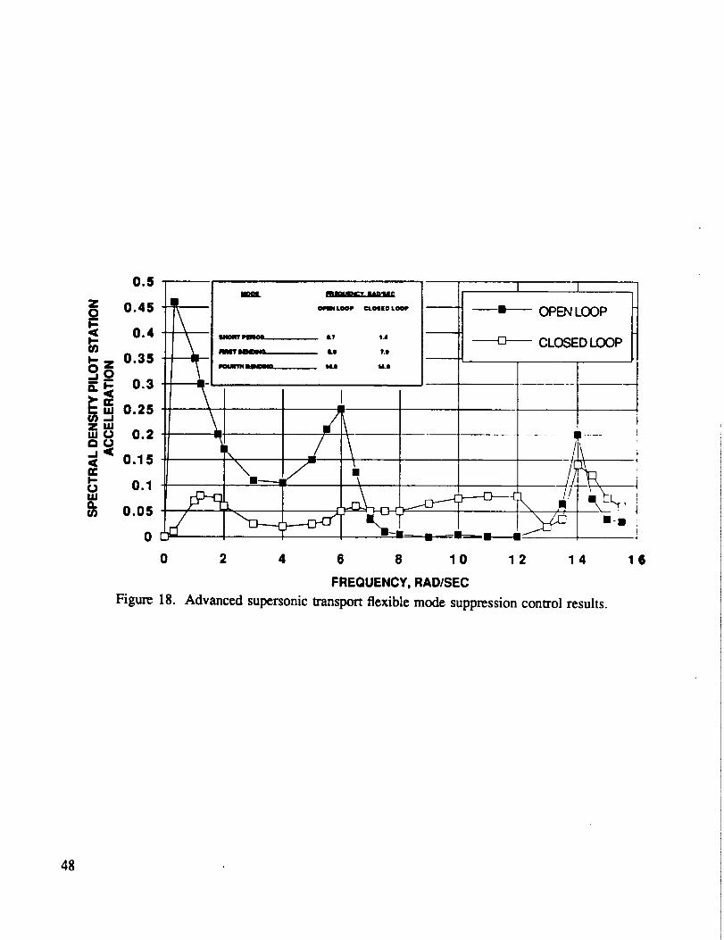
0.5 mmmmL _ l, I I
_) 0.45 _ m,._. _o,,oLo_, )I_ m- c)PEN LC)C)P
o.4 \ "_ "' '" II o-- CLOSEDLOOP--i-- --'_ " " Uo__0-&-- . . 1 1 I
_._ o.a ..........0.25d
0.15 i
,,o,o., !
0 "-' I __ u-m__ -__mm-.___m m/ --
0 2 4 6 8 10 12 14 16
FREQUENCY, RAD/SEC
Figure 18. Advanced supersonic transport flexible mode suppression control results.
48

..IuJ
la
<,I--UJ
LL
_ I'-- (D
(/)a.
la.UJI-"e_Z
UJ..I
o
49

5O

51

q_ _ m
1 1_D
52

!
i
"lm
-+
!-
+
53

J
qlmml
CI
i.Jomm i
0"1
.m.m_
c_ °-il 8
C_
54

55

m
i
56

57

Q.
2Q.
J
CQ
E
_=mu_ _ _n_
2
21 oo• _ G-'o "_
=_= _
=. . .o
58

<l
_" <l
n
r-,/ ]
M C
__o----_ E
59

60

mm
6!

J
ColiI
4)"00=S
i_._ __. .|_._ _ _
".____
.i
e_
,,i
e_
oIJ>
o
o
¢.,
e4
62

< __ Ez _
°_
tu
c°_
c
m
¢-
I.t.
63

1,
°_,,_¢-
0
©
0
0
° _,,,i
64

c_
65

<
<
,<
14,1
i
t...,
g
66


Form ApprovedREPORT DOCUMENTATION PAGE OMBNo.o7o4.o1_
Pu_c.rel_rting l_tden for this collectionof Inlormxtionis estimated Io average 1 hour per response, Includingthe time |of revlewinginSlrUCtions,se_uchingexistlngdata sources,garneringIns mamMunmgthe dais needed, and ¢oml_eling and reviewingthe collectionof tMormatlon. Send oommantorngatdlngthis burden esUmaleor any other aspect of Ihb¢ollecUonol Worm,ion. includingsuggestionsfo_reducingIbM burden, to WashingtonHeedquartsrl Services. Directorate for kdormlflon OPerations and Reports. 1215 JeffersonDavis Highway._une 1204, Atflngton,VA 22202.,4302, andto the Office of Managemen|and Budget.Paperwork ReductionPfojecl I0704-0188). Washington. DC 20503.
1. AGENCY USE ONLY (Leave blank) 2. REPORT DATE 3. REPORT TYPE AND DATES COVERED
March 1992 Contractor Report-Finali4. TITLE AND SUBTITLE 5. FUNDING NUMBERS
Design and Analysis Issues of Integrated Control Systems for High-Speed
Civil Transports
I. AUTHOR(S) NAS2-12722
Craig A. McCarty, John B. Feather, John R. Dykman, Mark A. Page, and
John Hodgldnson
7. PERFORMING ORGANIZATION NAME(S) AND ADDRESS(ES)
Douglas Aircraft Company
Engineering Technology and Advanced Aircraft Programs
Long Beach, California
9. SPONSORING/MONITORING AGENCY NAME(S) AND ADDRESS(ES)
National Aeronautics and Space Administration
Washington, DC 20546-0001
8. PERFORMING ORGANIZATIONREPORT NUMBER
H-1787
10. SPONSORING/MONITORINGAGENCY REPORT NUMBER
NASA CR-186022
11. SUPPLEMENTARYNOTESThis report was Ixcpamd for PRC Inc.,P.O.Box 273, Edwards, California93523-0273 by DouglasAircratt(3ompanyunder
subcoraractATD-91-DA C-7103. NASA TeclmicalMonitor was Brace G. Powers,NASA DrydenFlight ResearchFadlity,p.o. Box 273, Edwards, California93523-0273. NASA COTR for PRC Inc. Donald C. Bacon, Jr.,805-258-3484.
12s. DISTRIBUTION/AVAILABILITYSTATEMENT 12b. DISTRIBUTIONCODE
Unclassified -- Unlimited
Subject Category 08
13. ABSTRACT (Maximum 200 words)
A study was conducted to identify, rank, and define development plans for the critical guidance and
control design and analysis issues as related to an economically viable and environmentally acceptable
high-speed civil transport. The issues were identified in a muldstep process. First, pertinent literature
on supersonic cruise aircraft was reviewed, and experts were consulted to establish the fundamental
characteristics and problems inherent to supersonic cruise aircraft. Next, the advanced technologies and
strategies being pursued for the high-speed civil transport were considered to determine any additional
unique control problems the transport may have. Finally, existing technologies and methods were
examined to determine their capabilities for the design and analysis of high-speed civil transport control
systems, and to identify the shortcomings and issues. Three priority levels - mandatory, highly
beneficial, and desirable- were established. Within each of these levels, the issues were further ranked.
Technology development plans for each issue were def'med. Each plan contains a task breakdownand schedule.
17. SECURITY CLASSIFICATIONOF REPORT
Unclassified
NSN 7540-01-2a0-5500
14. SUBJECT TERMS
High-speed civil transport; Integrated control systems; Technology
development plans
18. SECURITY CLASSIFICATIONOF THIS PAGE
Unclassified
19. SECURITY CLASSIFICATIONOF ABSTRACT
Unclassified
15. NUMBER OF PAGES
"/216. PRICE CODE
A0420. LIMITATION OF ABSTRACT
Unlimited
Standard Form 298 (Rev. 2-89)Presc¢tbe¢l by AN&I 81¢1. Z31)-! 8
298-102

_JJ
JJ
I