Design, analysis, and fabrication of a piezoelectric force ...
14
Original Article Journal of Intelligent Material Systems and Structures 2019, Vol. 30(20) 3163–3176 Ó The Author(s) 2019 Article reuse guidelines: sagepub.com/journals-permissions DOI: 10.1177/1045389X19880003 journals.sagepub.com/home/jim Design, analysis, and fabrication of a piezoelectric force tray for total knee replacements Mohsen Safaei , Sylvain Dupre, Elias Hoummadi and Steven R Anton Abstract Force plates have been widely adopted in biomechanical gait analysis to measure reaction forces and the center of pres- sure. In this work, the force plate concept is miniaturized and extended for use within the polyethylene bearing insert of a total knee replacement. A simplified rectangular-shaped force plate with multiple integrated piezoelectric sensors, including designs with six and eight transducers, is presented in this work. The performance of the sensory system is investigated through finite element analysis and experimental validation. Initially, the ability of the two designs in sensing compartmental forces and contact point locations on one side of the force plate is numerically investigated. Selected designs of the force plate are then fabricated and used to experimentally validate the performance of the system. The results show a maximum error of less than 6% and 4.5% in compartmental force amplitude sensing for the force plates with six and eight transducers, respectively. The force plates were able to detect the contact point location with maxi- mum errors of less than 1 mm. The relatively small sensing error quantities show the potential of using a piezoelectric force plate sensor design in total knee replacement as well as other force sensing applications. Keywords Piezoelectric sensing, force plate, orthopedic sensing, total knee replacement 1. Introduction Conventional force plates have been widely used in the medical field to measure ground reaction forces of patients for a variety of biomechanical analyses. Researchers have utilized force plates for posturogra- phy, kinesiology, gait analysis, competitive sport, and rehabilitation (Hubbard et al., 2012; Peterson et al., 2017; Wong et al., 2015). Force plates are able to mea- sure several quantities including pressure distribution, center of pressure, amplitude of ground force, and amount of body sway. In their simplest form, force plates allow measurement of purely axial force, and use various geometries and various sensing technologies, such as piezoelectricity, capacitive sensing, and piezore- sistivity. Among the various sensing modalities in use in force plate technology, piezoelectric transducers (PZTs) have the advantage of providing self-powered sensing ability as a result of the direct piezoelectric effect that allows conversion of mechanical input to electrical out- put for energy harvesting purposes (Anton and Sodano, 2007). This provides a significant advantage for in vivo applications as it can obviate the need for a separate power source for the sensor. One of the original piezo- electric measurement systems for biomechanical applications was the force plate introduced to the mar- ket by the company KISTLER in 1984 (Schmiedmayer and Kastner, 1999). Improving the accuracy of this force plate has been ongoing research for more than two decades (Bobbert and Schamhardt, 1990; Middleton et al., 1999; Schmiedmayer and Kastner, 2000). In the biomechanical field, the force plate concept can be extended for use in total knee replacement (TKR) to improve the success of the surgical operation. For reference, the components of a TKR are shown in Figure 1(a). TKR is performed when the articular carti- lage of the knee becomes damaged or worn out and the level of pain is unbearable for the patient (Scuderi and Tria, 2006). It has been shown that the outcomes of TKR are dependent on several factors, such as implant design and material, fixation, and ligament balance Department of Mechanical Engineering, Tennessee Tech University, Cookeville, TN, USA Corresponding author: Steven R Anton, Department of Mechanical Engineering, Tennessee Tech University, 115 W. 10th St., Cookeville, TN 38505, USA. Email: [email protected]
Transcript of Design, analysis, and fabrication of a piezoelectric force ...

Original Article
Journal of Intelligent Material Systemsand Structures2019, Vol. 30(20) 3163–3176� The Author(s) 2019Article reuse guidelines:sagepub.com/journals-permissionsDOI: 10.1177/1045389X19880003journals.sagepub.com/home/jim
Design, analysis, and fabrication of apiezoelectric force tray for total kneereplacements
Mohsen Safaei , Sylvain Dupre, Elias Hoummadi and Steven R Anton
AbstractForce plates have been widely adopted in biomechanical gait analysis to measure reaction forces and the center of pres-sure. In this work, the force plate concept is miniaturized and extended for use within the polyethylene bearing insert ofa total knee replacement. A simplified rectangular-shaped force plate with multiple integrated piezoelectric sensors,including designs with six and eight transducers, is presented in this work. The performance of the sensory system isinvestigated through finite element analysis and experimental validation. Initially, the ability of the two designs in sensingcompartmental forces and contact point locations on one side of the force plate is numerically investigated. Selecteddesigns of the force plate are then fabricated and used to experimentally validate the performance of the system. Theresults show a maximum error of less than 6% and 4.5% in compartmental force amplitude sensing for the force plateswith six and eight transducers, respectively. The force plates were able to detect the contact point location with maxi-mum errors of less than 1 mm. The relatively small sensing error quantities show the potential of using a piezoelectricforce plate sensor design in total knee replacement as well as other force sensing applications.
KeywordsPiezoelectric sensing, force plate, orthopedic sensing, total knee replacement
1. Introduction
Conventional force plates have been widely used in themedical field to measure ground reaction forces ofpatients for a variety of biomechanical analyses.Researchers have utilized force plates for posturogra-phy, kinesiology, gait analysis, competitive sport, andrehabilitation (Hubbard et al., 2012; Peterson et al.,2017; Wong et al., 2015). Force plates are able to mea-sure several quantities including pressure distribution,center of pressure, amplitude of ground force, andamount of body sway. In their simplest form, forceplates allow measurement of purely axial force, and usevarious geometries and various sensing technologies,such as piezoelectricity, capacitive sensing, and piezore-sistivity. Among the various sensing modalities in use inforce plate technology, piezoelectric transducers (PZTs)have the advantage of providing self-powered sensingability as a result of the direct piezoelectric effect thatallows conversion of mechanical input to electrical out-put for energy harvesting purposes (Anton and Sodano,2007). This provides a significant advantage for in vivoapplications as it can obviate the need for a separatepower source for the sensor. One of the original piezo-electric measurement systems for biomechanical
applications was the force plate introduced to the mar-ket by the company KISTLER in 1984 (Schmiedmayerand Kastner, 1999). Improving the accuracy of thisforce plate has been ongoing research for more thantwo decades (Bobbert and Schamhardt, 1990;Middleton et al., 1999; Schmiedmayer and Kastner,2000).
In the biomechanical field, the force plate conceptcan be extended for use in total knee replacement(TKR) to improve the success of the surgical operation.For reference, the components of a TKR are shown inFigure 1(a). TKR is performed when the articular carti-lage of the knee becomes damaged or worn out and thelevel of pain is unbearable for the patient (Scuderi andTria, 2006). It has been shown that the outcomes ofTKR are dependent on several factors, such as implantdesign and material, fixation, and ligament balance
Department of Mechanical Engineering, Tennessee Tech University,
Cookeville, TN, USA
Corresponding author:
Steven R Anton, Department of Mechanical Engineering, Tennessee Tech
University, 115 W. 10th St., Cookeville, TN 38505, USA.
Email: [email protected]

(Rand et al., 2003; Sharkey et al., 2014). Changes in thecenter of pressure and contact point locations, andmagnitude of forces on the cartilage surfaces of theknee are important markers in the assessment of thejoint (Marouane et al., 2016). In order to increase thesuccess of knee replacement operations, the concept ofprosthesis with integrated sensors was born with thework of Taylor et al. in 1998 (Taylor et al., 1998). Theyproposed and implanted a large instrumented distalfemoral implant to measure in vivo loading of the kneejoint. The system was able to measure the axial forces fordifferent activities such as standing, walking, and stairclimbing, and transmit the information with a telemetrysystem. The system was powered by an external magneticcoil. In 2005, D’Lima et al. (D’Lima et al., 2005; Morriset al., 2001) proposed another implementation of aninstrumented contemporary knee implant. They devel-oped a design in which load cells were placed in the tibialcomponent to measure uniaxial forces and center of pres-sure, and a wireless transmitter was housed in the tibialstem for data transmission. The system was poweredfrom an external coil located around the patient’s knee.
In order to solve the problems related to the use ofexternal electromagnetic coils for powering theembedded sensors, the use of piezoelectric and tribo-electric generators has been suggested by researchers. Aconceptual design of a smart knee implant equippedwith a triboelectric energy harvesting system was pro-posed by Ibrahim et al. showing the potential of tribo-electric generators to power the embedded sensorysystems in TKR (Ibrahim et al., 2018). Platt et al.(2015a, 2015b) were the first to propose the use of PZTsin order to create a self-sufficient energy system. In2011, Almouahed et al. (2011) proposed a new instru-mented prototype with four PZTs, based on the workof D’Lima et al. (2005). The prototype was able to sensethe center of pressure and to harvest energy for the pur-pose of powering a measurement circuit and integratedtelemetry system. Although the works of Platt et al.(2005b) and Almouahed et al. (2011) show the ability ofPZTs to measure applied force as well as to harvest
energy from knee motion, the geometry of the implantis highly modified in both designs. The suggestedincrease in the height of the tibial component requiresmore bone to be removed during surgery and increasesthe potential for instability after the operation.
To alleviate the problems posed by the work ofAlmouahed et al. (2011) and Platt et al. (2005b), ourprevious work (Safaei et al., 2017) suggested placingpiezoelectric sensors within the ultra-high-molecular-weight (UHMW) polyethylene insert of the kneeimplant. Our initial works utilized a simplistic proto-type of a UHMW disk with a single-embedded PZT todemonstrate the possibility of sensing and energy har-vesting from knee motion, and performed a parametricstudy on the performance of the system. Continuingour work (Safaei et al., 2018b), we then proposed theintegration of four PZTs into a realistic polyethyleneinsert (three-dimensional (3D) printed prototype basedon a 3D scan of a real insert) to sense the magnitudeand center of pressure of the applied force for simu-lated walking, as shown in Figure 1(b).
This article aims to extend our previous work (Safaeiet al., 2018b) by synergistically merging the concept ofpiezoelectric force plates and integrated TKR sensing toallow in vivo measurement of compartmental forcemagnitudes and locations. For this purpose, the poly-ethylene insert has been simplified into a miniatureforce plate equipped with multiple embedded piezoelec-tric sensors. Simplifying the bearing component mini-mizes the sources of errors that can be encountered inthis feasibility study as a result of the complex geometryof a real polyethylene insert. The performance of theforce plate is studied through finite element (FE) model-ing and post-processing of the data collected therefrom.A parametric study on the dimensional parameters isperformed in FE to find the best sensor arrangementwith respect to minimum error in sensing performance.The numerical simulations are validated using severalexperiments performed on fabricated prototypes of thedesigns chosen based on the selected arrangement foundfrom the parametric study.
Figure 1. Schematic of (a) knee implant components (image courtesy of www.stryker.com) and (b) polyethylene insert withembedded piezoelectric transducers (Safaei et al., 2018b).
3164 Journal of Intelligent Material Systems and Structures 30(20)
2. Force plate design
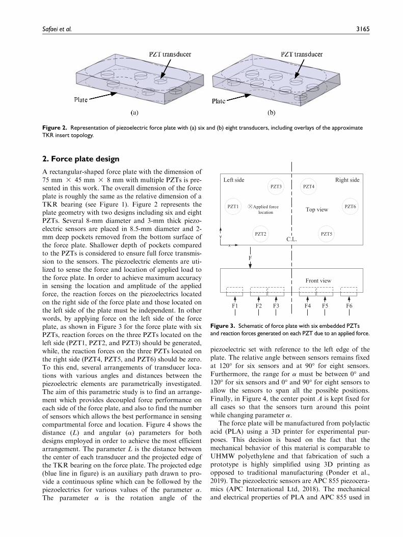
A rectangular-shaped force plate with the dimension of75 mm 3 45 mm 3 8 mm with multiple PZTs is pre-sented in this work. The overall dimension of the forceplate is roughly the same as the relative dimension of aTKR bearing (see Figure 1). Figure 2 represents theplate geometry with two designs including six and eightPZTs. Several 8-mm diameter and 3-mm thick piezo-electric sensors are placed in 8.5-mm diameter and 2-mm deep pockets removed from the bottom surface ofthe force plate. Shallower depth of pockets comparedto the PZTs is considered to ensure full force transmis-sion to the sensors. The piezoelectric elements are uti-lized to sense the force and location of applied load tothe force plate. In order to achieve maximum accuracyin sensing the location and amplitude of the appliedforce, the reaction forces on the piezoelectrics locatedon the right side of the force plate and those located onthe left side of the plate must be independent. In otherwords, by applying force on the left side of the forceplate, as shown in Figure 3 for the force plate with sixPZTs, reaction forces on the three PZTs located on theleft side (PZT1, PZT2, and PZT3) should be generated,while, the reaction forces on the three PZTs located onthe right side (PZT4, PZT5, and PZT6) should be zero.To this end, several arrangements of transducer loca-tions with various angles and distances between thepiezoelectric elements are parametrically investigated.The aim of this parametric study is to find an arrange-ment which provides decoupled force performance oneach side of the force plate, and also to find the numberof sensors which allows the best performance in sensingcompartmental force and location. Figure 4 shows thedistance (L) and angular (a) parameters for bothdesigns employed in order to achieve the most efficientarrangement. The parameter L is the distance betweenthe center of each transducer and the projected edge ofthe TKR bearing on the force plate. The projected edge(blue line in figure) is an auxiliary path drawn to pro-vide a continuous spline which can be followed by thepiezoelectrics for various values of the parameter a.The parameter a is the rotation angle of the
piezoelectric set with reference to the left edge of theplate. The relative angle between sensors remains fixedat 120� for six sensors and at 90� for eight sensors.Furthermore, the range for a must be between 0� and120� for six sensors and 0� and 90� for eight sensors toallow the sensors to span all the possible positions.Finally, in Figure 4, the center point A is kept fixed forall cases so that the sensors turn around this pointwhile changing parameter a.
The force plate will be manufactured from polylacticacid (PLA) using a 3D printer for experimental pur-poses. This decision is based on the fact that themechanical behavior of this material is comparable toUHMW polyethylene and that fabrication of such aprototype is highly simplified using 3D printing asopposed to traditional manufacturing (Ponder et al.,2019). The piezoelectric sensors are APC 855 piezocera-mics (APC International Ltd, 2018). The mechanicaland electrical properties of PLA and APC 855 used in
Figure 2. Representation of piezoelectric force plate with (a) six and (b) eight transducers, including overlays of the approximateTKR insert topology.
Figure 3. Schematic of force plate with six embedded PZTsand reaction forces generated on each PZT due to an applied force.
Safaei et al. 3165

this study are listed in Table 1. The material propertiesof PLA and APC 855 (PZT-5H) are taken from themanufacturer specifications (Polymaker, 2018; APCInternational Ltd, 2018). It is necessary to note thatPZT-5H ceramics are widely used in various sensing,actuation, and energy harvesting applications due totheir relatively high electromechanical coupling, andare selected in this study due to availability (Jaffe,1971). Since the goal of this study is to investigate thefeasibility of contact force location and magnitude sen-sing using PZTs, the biocompatibility and durability ofpiezoelectric elements have not been considered. Forthe end product, the PZT-5H ceramics need to bereplaced with a durable piezoelectric sensor packagesuch as PI Ceramic GmbH (PICMA) transducersencapsulated in biocompatible compounds such aspolydimethylsiloxane (PDMS) (Safaei et al., 2018a).
3. Modeling
3.1. FE model
In this section, FE modeling is performed on the pro-posed force plate designs in order to develop the effec-tive reaction forces on the PZTs. The FE modeling isperformed in CATIA (Dassault Systemes SE), and
models are developed for the designs with both six andeight embedded piezoelectric ceramics on the bottomsurface of the force plate, as shown in Figure 5. In addi-tion, a hemispherical-shaped forcing tool is designed toapply load to the plate and is also used in experimentaltests (see section ‘‘Test setup’’). It is necessary to men-tion that the piezoelectrics are modeled as passive ele-ments in FE modeling to obtain the reaction forces,and the electromechanical coupling is considered in theexperimental part of this study as described in section‘‘Electromechanical model of piezoelectric transducers.’’A static load of 1500 N is applied to the force platethrough the forcing tool. The hemispherical forcing toolreplicates the loading condition on a knee bearing insertsurface due to the curved contact surfaces of both theinsert and the femoral component. The elements usedin CATIA are 3D tetrahedral parabolic elements with amesh size of 3 mm. For all simulations, convergence inthe numerical results is obtained by confirming that thetotal reaction force on all PZTs is equal to the appliedforce. As a result of the convergence study, the mesh isrefined to 0.3 mm for the contact areas and for thepiezoelectrics. The material properties for the piezoelec-tric elements and PLA component are listed in Table 1,and the forcing tool is considered to be made fromstructural steel.
Figure 4. Representation of the parameters, a and L, studied in the parametric analysis for (a) six and (b) eight transducers.
Table 1. Material properties of PLA and APC 855e0 = 8.854 3 10212 F/m.
Material properties PLA bearing APC 855
Young’s modulus (GPa) 2.6 59Poisson’s ratio 0.42 0.35Density (kg/m3) 1240 7600Piezoelectric constant,d33 (pC/N)
– 630 3 10212
Piezoelectric constant,d31 (pC/N)
– 2276 3 10212
Piezoelectric constant,d15 (pC/N)
– 720 3 10212
Relative permittivity,eT33=e0
– 3300
PLA: polylactic acid.
Figure 5. Bottom view of the meshed finite element model forforce plates with (a) six and (b) eight transducers.
3166 Journal of Intelligent Material Systems and Structures 30(20)

The contacts between the sensors and the plate, andbetween the plate and the forcing tool are simulated asfrictionless without separation. The underlying surfacesof the sensors are fixed with a planar connection.Perpendicular to the surface of the plate, a sliding linkgoverns the forcing tool, allowing the application of astrictly axial force. The reaction forces on the sensorsare subsequently measured at the end of eachsimulation.
3.2. Force and moment equilibrium expressions
Given a uniaxial compression force applied on one sideof the force plate, reaction forces are created on thePZTs located in each side of the plate. Using momentequilibrium, the location of applied force on the forceplate in the x- and y-directions (see Figure 3) can becalculated as
xF =
Pni= 1
xnRn
Pni= 1
Rn
ð1Þ
yF =
Pni= 1
ynRn
Pni= 1
Rn
ð2Þ
where xF is the location of the force in the x-direction,yF is the location of the force in the y-direction, n is thenumber of sensors on the forced side of the force plate(three or four transducers), xn and yn are the coordi-nates of the center of each sensor, and Rn is the reactionforce associated with each sensor. The amplitude ofapplied force Fz is the summation of the individualreaction forces on each piezoelectric, as given by
FZ =Xn
i= 1
Rn ð3Þ
In order to evaluate the performance of the forceplates in sensing the location and amplitude of theapplied force, the deviation between the actual and cal-culated location of applied force can be found using
xdev = xF � xinj j ð4Þ
ydev = yF � yinj j ð5Þ
Sdev =ffiffiffiffiffiffiffiffiffiffiffiffiffiffiffiffiffiffiffiffiffix2
dev + y2dev
qð6Þ
where xdev and ydev are the deviation in calculated loca-tion of force in the x- and y-directions, respectively, thesubscript in shows the actual quantities of input forcelocation, and Sdev is the total deviation of calculatedlocation. In addition, the error in calculated amplitudeof force can be obtained using
eF =FZ � Finj j
FZ
3 100 ð7Þ
where eF is the error in calculated force, and Fin is theinput force.
3.3. Electromechanical model of PZTs
In an actual piezoelectric sensing system, the measur-able quantity is the electrical output (voltage) of thePZTs. In order to develop the reaction forces from mea-sured voltage outputs in the experimental study con-ducted herein, an electromechanical model is utilized,as described here. The mathematical model governingthe electromechanical behavior of piezoelectric crystalswas predicted and verified for the first time by brothersCurie: Pierre and Jacques, in 1880 (Curie and Curie,1881). The existence of the reverse effect was predictedthe following year by Gabriel Lippmann (Lippmann,1881). Woldemar Voigt (1910) rigorously defined theset of piezoelectric constants in the formalism of tensor-ial analysis. However, in the case of uniform axial com-pression in direction 3 (z), the electromechanicalcoupling constitutive equations for a piezoelectric ele-ment are given by
S3 = sE33T3 + d33E3
D33 = d33T3 + eT33E3
ð8Þ
where S represents the mechanical strain, sE is themechanical compliance, T is the mechanical stress, d33is the piezoelectric strain constant, E is the electricalfield, D is the electric displacement, and eT is the dielec-tric constant. The relationship between the electric dis-placement and the ratio of the voltage across a resistorconnected in parallel to a PZT can be obtained usingthe cylindrical generalization of Gauss’s law given by
d
dt
ð~D �~ndA
� �=
V tð ÞR
ð9Þ
where ~n is the outward normal vector of the surface ofthe electrode, A is the cross section of the piezoelectricelement, ~D is the vector of electric displacement, andV tð Þ is the voltage across the resistor R. Substitutingequation (8) into equation (9), the governing differen-tial equation of the piezoelectric element under axialdynamic force can be obtained as
Cp
dV (t)
dt+
V (t)
R= d33
dF(t)
dtð10Þ
where Cp is the capacitance of the PZT with thicknessh, given by
Cp =eT
33A
hð11Þ
Safaei et al. 3167

Equation (10) can be rewritten in the Laplacedomain in terms of the transfer function as
V (s)
F(s)=
Cps+ 1R
d33sð12Þ
where s is the Laplace variable.
3.4. Modeling results
The reaction forces associated with each sensor as afunction of the angular (a) and distance (L) parametersare used in a MATLAB (The MathWorks, Inc.) codebased on equations (1) to (7) in order to calculate thedeviation in the location of force and error in the ampli-tude of force. Note, these calculations are performedbased on the reaction forces measured on each piezo-electric sensor since the piezoelectric elements are mod-eled as passive supports in FE simulation. The result ofthese simulations for the force plates with six and eightPZTs are presented in this section.
3.4.1. Results for six sensors. For the initial parametricanalysis, the location of applied force is fixed at theposition xin = 21:5mm and yin = 23mm. This positionrepresents a typical contact location of the femoralcomponent and tibial bearing insert of a TKR for nor-mal standing obtained from Marouane et al. (2016).The deviation in the detected location of the force givenas a function of the evolution of the angular parameter(a) is displayed in Figure 6(a) while the parameter L iskept at 8 mm. In addition, the error in total force mea-sured by the three sensors located on the load bearingside of the force plate compared to the input force isplotted in Figure 6(b).
The total deviation in the location of force shown inFigure 6(a) fluctuates between 0.5 and 0.9 mm bychanging the angular parameter, and the minimum
deviation is achieved at an angle of 80�. The deviationin measured location of force from actual quantitiescan be attributed to the fact that the force distributionon each sensor is not uniform, therefore, the effectivelocation of force is not located on the center of the crosssection of the sensor, while, in the calculations, the cen-ter point of the cross section is considered as the effec-tive location of force. It can be seen from Figure 6(b)that the errors in force sensing are very small; they areless than or equal to 5 3 1025% and can be neglected.These errors are due to small reaction forces generatedon the three PZTs located on the opposite side of theplate.
Considering the chosen angular parameter equal to80� for minimum error, the distance parameter L isthen varied to achieve the most efficient arrangementof PZTs inside the force plate. The deviation in thesensed location and error in the amplitude of forcegiven as a function of the evolution of the distanceparameter L are displayed in Figure 7. From Figure7(a), the minimum deviation in the x- and y-directionsare 0.20 and 0.11 mm, respectively, with angular para-meter a= 808 and distance parameter L= 10mm. Theerror in force sensing presented in Figure 7(b) is lessthan 5 3 1025%, demonstrating that the right and leftparts of the force plate are nearly independent for anyvalue of the parameters. Based on the FE simulationresults, the best arrangement of six PZT sensors is cho-sen with parameters a= 808 and L= 10mm, whichpresents a total deviation of 0.20 mm and an error of1.62 3 1026% in the amplitude of force.
3.4.2. Results for eight sensors. The location of appliedforce remains at xin = 21:5mm and yin = 23mm for theanalysis with eight sensors. The deviation in thedetected location of the force given as a function of theevolution of the angular parameter (a) is displayed in
(a) (b)
Figure 6. (a) Deviation in sensed location of the force and (b) error in the sensed force amplitude as a function of a for designwith six transducers (L fixed at 8 mm).
3168 Journal of Intelligent Material Systems and Structures 30(20)

Figure 8(a) while the parameter L is kept at 8 mm. Inaddition, the error in total force measured by the foursensors located on the load bearing side of the forceplate compared to the input force is plotted in Figure8(b).
For the simulation with eight sensors, the calcula-tion range of a is between 0� and 90�. Considering thefluctuations observed in the diagrams presented inFigure 8(a), the deviation in the location of force issimulated for the particular range of a between 43� and55� with a smaller step size in order to increase theaccuracy of the results. The results of the refined simu-lation are illustrated in the inset plot in Figure 8(a).According to the results, the lowest deviation corre-sponds to an angle of 47�. From Figure 8(b), the errorin the amplitude of force is particularly low due to verysmall reaction forces measured on the four PZTs placedon the opposite side of the force plate.
For the chosen angular parameter of a= 478, thedeviation in the location of force obtained as a functionof the evolution of the distance parameter L is displayedin Figure 9(a). The minimum deviation in location offorce in the x- and y-directions are 0.002 and 0.025 mm,respectively, and are achieved at L= 8mm. FromFigure 9(b), the error in sensed force is negligible for theentire distance parameter range, demonstrating that theright and left parts of the force plate are nearly indepen-dent for any value of the parameters. Based on theFE simulation results, the best arrangement of eightPZT sensors is chosen with parameters a= 478 andL= 8mm, which presents a total deviation of 0.025 mmand an error of 5 3 1025% in the amplitude of force.
3.4.3. Selected arrangement. Considering the results pre-sented in the previous sections, the best arrangement ofPZT sensors inside the force plates is presented in this
(a) (b)
Figure 7. (a) Deviation in sensed location of the force and (b) error in the sensed force amplitude as a function of L for design withsix transducers (a fixed at 80�).
(a) (b)
Figure 8. (a) Deviation in sensed location of the force and (b) error in the sensed force amplitude as a function of a for designwith eight transducers (L fixed at 8 mm).
Safaei et al. 3169

section. For the force plate with six sensors, the lowestdeviation and error in the sensed location and ampli-tude of force is obtained an angle of 80� and with a dis-tance of 10 mm, which results in the sensorarrangement shown in Figure 10(a). For the force platewith eight sensors, the optimum performance isachieved with an angle of 47� and distance parameterof 8 mm, as shown in Figure 10(b). It is necessary tonote that the design with eight PZTs outperforms thedesign with six PZTs with respect to deviation in sen-sing the location of force. However, there is a tradeoffbetween the accuracy of the sensory system and thepower consumption and size of the required electronics,as larger number of sensors results in more signal con-ditioning electronics and higher power requirement.This needs to be considered when designing the forceplate for a particular application.
3.4.4. Performance under moving load location. The resultsobtained in the previous sections are obtained for a
fixed location of applied force. It is necessary to investi-gate the performance of the force plates when the loca-tion of the applied force is varied. Figure 11 illustratesthe deviation in the location and error in the amplitudeof applied force measured by reaction forces on thePZT sensors for the design with six sensors for nine dif-ferent locations of applied force (as shown in the insetfigure in Figures 11(a) and 12(a)). The area over whichthe nine locations of applied force encompasses is cho-sen based on the actual contact locations of the femoralcomponent and tibial bearing insert of a TKR duringvarious stages of flexion-extension and internal-externalrotation obtained from the literature (Marouane et al.,2016). From Figure 11(a), the amount of deviation inthe location of force is relatively high for points 1, 7,and 9. This deviation is mostly due to the deviation ofthe effective location of force from the center of thecross section of the sensor, as discussed in section‘‘Results for six sensors.’’ Furthermore, Figure 11(b)shows that the error in amplitude of sensed force is rel-atively high for points 6 and 8 as a result of small
(a) (b)
Figure 9. (a) Deviation in sensed location of the force and (b) error in the sensed force amplitude as a function of L for design witheight transducers (a fixed at 47�).
Figure 10. Optimum arrangement of sensors inside the force plate for designs with (a) six and (b) and eight transducers (alldimensions in mm).
3170 Journal of Intelligent Material Systems and Structures 30(20)

tensile forces generated on some of the sensors due tothe separation-free boundary condition between thesensors and polyethylene insert. From these results, theapplication of the design with six sensors is limited to asmaller area than the original area investigated in thisstudy and reported in the literature. This is due to theproximity of the force locations to the borders of theresulting area covered by the PZT sensors. Usingsmaller PZT sensors, the covered area (i.e. effective sen-sing area) can be increased. Similar simulation resultsfor the force plate with eight transducers are displayedin Figure 12. It can be seen from the diagrams that thedesign with eight PZTs presents less deviation in loca-tion of force sensing and excellent error in force ampli-tude sensing for various force locations. It is necessaryto note that points 1 and 9 are extreme points placedoutside of the typical contact area between the femoraland tibial components and the relatively high error inthese areas will not affect the performance of the forceplate.
4. Experimentation
4.1. Test setup
Based on the selected arrangement of PZT sensorsinside the force plates obtained from FE simulationand presented in Figure 10 for the designs with six andeight PZTs, prototypes of these force plates are fabri-cated and experimentally tested. In order to run com-pression tests on the force plates, a customized design,as shown in Figure 13(a), is developed and consists ofthe force plate, PZT sensors, a guide plate, and a bot-tom plate. The guide plate is added to ensure accurateplacement of the transducers, and the bottom plateallows appropriate wiring of the PZT ceramics whileavoiding soldering, which improves the durability ofthe sensor electrodes. Fabricated force plates with sixand eight PZTs are shown in Figure 13(b) and (c),respectively.
The fabricated prototypes are then placed in a loadframe in order to perform compression tests. The test
(a) (b)
Figure 11. (a) Deviation in sensed location of the force and (b) error in the sensed force amplitude for nine different applied loadlocations for design with six transducers.
(a) (b)
Figure 12. (a) Deviation in sensed location of the force and (b) error in the sensed force amplitude for nine different applied loadlocations for design with eight transducers.
Safaei et al. 3171

setup is shown in Figure 14(a) and includes a loadframe, the force plate system, and a data acquisition(DAQ) system. The tests are carried out using an MTS(MTS Systems Corp.) 810 load frame, which applies asinusoidal compression force with a minimum force of50 N and a maximum force of 1500 N at 1 Hz fre-quency at different locations on the force plates. Adetailed view of the experimental setup is displayed inFigure 14(b). The customized fixture allows the transla-tional adjustment of the force plate with the help of theadjustment screws. Note, the screws are loose duringthe compression tests in order to avoid external forceson the force plate. The forcing tool is designed to
replicate the curved contact region between the femoralcomponent and bearing insert of a TKR. Using electricposts wrapped in copper tape, the PZT sensors are con-nected to an external load resistance of 1 MO (1 MO isa common input impedance for analog-to-digital con-verters (ADCs), therefore, is selected in this study), andthe voltage signal across the resistor is measured usingtwo NI 9215 DAQ modules placed in a cDAQ-9178chassis (National Instruments Corp.). A multichannelLabVIEW (National Instruments Corp.) program isutilized to record the voltage signals generated fromthe PZT sensors at a sampling rate of 1000 Hz. Theactual location of the applied force is recorded using a
Figure 13. (a) Exploded view of the experimental force plate prototype, and separated top view for the bearing design with (b) sixand (c) eight transducers.
Figure 14. (a) Experimental setup and (b) close-up view of forcing tool, force plate, pressure film, and fixture.
3172 Journal of Intelligent Material Systems and Structures 30(20)

medium-range Prescale pressure sensitive film (FujifilmCorp.) placed on the top surface of the force plate, asshown in Figure 14(b). The pressure sensitive films arescanned and an image processing code is used in orderto determine the location of the contact area. The rela-tive location of the forcing tool and the force plate isvaried in different experiments (three locations for eachforce plate) in order to investigate the sensing perfor-mance as the load location varies.
4.2. Test results
Three tests are performed on each force plate usingrandom locations of applied force to the force plate,each with identical input load profile. The locations ofapplied force are limited to the actual contact areas ofthe femoral component and tibial bearing of TKRreported in the literature (Marouane et al., 2016). Thevoltage signals are measured from each sensor acrossthe load resistors. Post-processing is performed on thevoltage data in MATLAB to first remove noise andthen calculate the reaction forces according to equation(12). Equations (1) and (2) are then used to calculatethe location of the applied force. Finally, the total forceapplied to the force plate can be calculated from thereaction forces generated on each PZT sensor usingequation (3). Figure 15(a) and (b) show the calculatedtotal force from the voltage signals obtained from thetransducers for three compression tests (locations ofapplied force for the three tests shown later in Figure16) compared to the input force profile for the designswith six and eight sensors, respectively. The maximumerrors in sensed force using the six sensor force plateare 5.51% (79.9 N), 0.58% (8.42 N), and 2.47%(35.8 N) for tests 1, 2, and 3, respectively. The maxi-mum error quantities in measured force using the eightsensor force plate are 4.38% (63.75 N), 3.78% (55 N),and 4.39% (63.89 N) for tests 1, 2, and 3, respectively.
In addition, the location of force is calculated for alltests and the deviation from the actual locationsrecorded by the pressure films are obtained. Figure 16displays the deviation in measured location of forcecompared to the actual quantities in x- and y-directionsfor the three different tests for each force plate design.Figure 16(a) to (c) shows the results for the force platewith six sensors, and Figure 16(d) to (f) shows theresults for the force plate with eight sensors. It is neces-sary to mention that the location of applied force foreach test is chosen randomly in order to evaluate theoverall performance of the sensing system. For refer-ence, the actual locations of applied force measured bypressure films are shown beneath each figure. Theresults shows that the sensed location of applied forcevaries periodically in time at the same frequency as thefrequency of applied force, with the points of maximumdeviation corresponding to the minima of the inputforce profile. This phenomenon can be attributed tolow voltage output, hence lower sensitivity, for lowapplied forces. The fluctuation in the deviation ofsensed location from the actual quantities is around60.2 mm with a maximum deviation of under 1 mmfor both designs and all tests. It should be noted thatthe results obtained from experimental testing pre-sented in Figure 16 show higher deviation in measuredlocation of force than the deviations obtained from FEmodeling presented in Section ‘‘Modeling results’’,which can be attributed to errors in prototype fabrica-tion, DAQ measurements, piezoelectric material prop-erties used in the post-processing, non-uniform forcedistribution on the sensors, and inaccuracies in pressurefilm measurements.
Considering the experimental results presented forthe force plates with six and eight sensors, it can be con-cluded that both force plates are able to measure theforce quantities and the location of contact points witha small error. The maximum error in sensing the force
(a) (b)
Figure 15. Amplitude of the measured and input forces over time obtained from three tests for the force plate with (a) six and (b)eight transducers.
Safaei et al. 3173

is under 6% for the design with six sensors and under4.5% for the design with eight sensors, and the error insensed location of contact points is under 1 mm forboth force plates. Note, incorporating less number ofsensors can lead to smaller electronics, less data post-processing, and lower power consumption, which needsto be considered in the design of the final product. Thesmall sensing errors show promising potential of piezo-electric force sensors for use in practical applications,especially in TKR. It should be noted that the resultspresented in this article depend on the specific TKRgeometry chosen for analysis, and that the arrangementof PZTs should be optimized for a given TKR forceplate geometry using the approach presented in thisstudy.
5. Conclusion
In this work, the feasibility of detecting the locationand amplitude of applied force using a piezoelectricforce plate with special application in TKR is investi-gated. Two designs of rectangular-shaped force plateswith six and eight embedded PZTs are proposed. Thesymmetric force plate design places equal number ofsensors in the left half and right half of the plate. Inorder to achieve desirable performance, the left sideand right side of the force plate are required to act inde-pendently. Several FE studies are performed on the twoforce plate designs with various transducer arrange-ments in order to find the best arrangement with maxi-mum sensing performance with respect to sensing the
Figure 16. Evolution of the deviation between actual location and measured location from PZTs obtained from (a) test 1, (b) test2, and (c) test 3 for the force plate with six sensors; and (d) test 1, (e) test 2, and (f) test 3 for the force plate with eight sensors.
3174 Journal of Intelligent Material Systems and Structures 30(20)

amplitude and location of applied force. Simulationresults for the chosen arrangements showed very smallerrors in sensing performance which demonstratesdecoupling of the force plate in the left and right sides.Based on the designs chosen from FE analysis, experi-mental prototypes with six and eight transducers arefabricated and tested under cyclic compression loadusing a load frame. During experimental testing, thevoltage signals generated by the PZTs are measuredacross 1 MO load resistors connected in parallel to thesensors. The measured voltages are processed in aMATLAB code that leverages an electromechanicallycoupled piezoelectric model along with force andmoment balance expressions in order to obtain thereaction forces generated on each piezoelectric as wellas the location of applied force. Three tests are per-formed, each using an identical load profile but withthe location of applied force varied. Results show amaximum error of less than 6% in force sensing and amaximum deviation under 1 mm in location sensing forthe force plate with six sensors. The error in force sen-sing is less than 4.5% and the deviation in location sen-sing is under 1 mm for the force plate with eight PZTs.The errors attained experimentally are generally higherthan those obtained using FE simulation due to fabri-cation tolerances, DAQ errors, and post-processing.Overall, the small error in sensing performance of theproposed force plates shows the promising potential ofusing piezoelectric force plates in practical applicationssuch as force and contact point sensing in TKR. Inaddition, the coupled electromechanical performanceof PZTs allows the proposed force plates to operate asself-powered sensors under dynamic loading due to thegeneration of useful electrical energy by the piezoelec-trics which can be stored and used to power the sensor.Moreover, the piezoelectric force sensing device sug-gested in this work is not limited to the knee replace-ment environment or biomedical applications, and canbe scaled for use in other force sensing applications inorder to develop alternative self-powered sensorysystems.
Declaration of conflicting interests
The author(s) declared no potential conflicts of interest withrespect to the research, authorship, and/or publication of thisarticle.
Funding
The author(s) disclosed receipt of the following financial sup-port for the research, authorship, and/or publication of this
article: Research reported in this publication was supportedby the National Institute of Arthritis and Musculoskeletaland Skin Diseases of the National Institutes of Health underAward Number R15AR068663. The content is solely the
responsibility of the authors and does not necessarily repre-sent the official views of the National Institutes of Health.
ORCID iDs
Mohsen Safaei https://orcid.org/0000-0002-8312-3000Steven R Anton https://orcid.org/0000-0003-2777-5458
References
Almouahed S, Gouriou M, Hamitouche C, et al. (2011)
Design and evaluation of instrumented smart knee
implant. IEEE Transactions on Biomedical Engineering
58(4): 971–982.Anton SR and Sodano HA (2007) A review of power harvest-
ing using piezoelectric materials (2003–2006). Smart Mate-
rials and Structures 16(3): R1–R21.APC International Ltd (2018) Physical and piezoelectric prop-
erties of APC materials. Available at: https://www.ameri-
canpiezo.com/apc-materials/physical-piezoelectric-proper-
ties.html (accessed 11 November 2018).Bobbert MF and Schamhardt HC (1990) Accuracy of deter-
mining the point of force application with piezoelectric
force plates. Journal of Biomechanics 23(7): 705–710.Curie J and Curie P (1881) Contractions et dilatations pro-
duites par des tensions electriques dans les cristaux hemi-
edres a faces inclinees. Comptes rendus de l’Academie des
Sciences 93: 1137–1140.D’Lima DD, Townsend CP, Arms SW, et al. (2005) An
implantable telemetry device to measure intra-articular
tibial forces. Journal of Biomechanics 38(2): 299–304.Hubbard B, Pothier D, Hughes C, et al. (2012) A portable,
low-cost system for posturography: a platform for longitu-
dinal balance telemetry. Journal of Otolaryngology-Head
and Neck Surgery 41(1): S31–S35.Ibrahim A, Jain M, Salman E, et al. (2018) A smart knee
implant using triboelectric energy harvesters. Smart Mate-
rials and Structures 28: 025040.Jaffe B (1971) Piezoelectric Ceramics. New York: Academic
Press.Lippmann GJ (1881) Principe de la conservation de l’electri-
cite ou second principe de la theorie des phenomenes elec-
triques. Annales de Chimie et de Physique 24: 145–177.Marouane H, Shirazi-Adl A and Adouni M (2016) Altera-
tions in knee contact forces and centers in stance phase of
gait: a detailed lower extremity musculoskeletal model.
Journal of Biomechanics 49(2): 185–192.Middleton J, Sinclair P and Patton R (1999) Accuracy of cen-
tre of pressure measurement using a piezoelectric force
platform. Clinical Biomechanics 14(5): 357–360.Morris BA, D’Lima DD, Slamin J, et al. (2001) E-Knee: evo-
lution of the electronic knee prosthesis. The Journal of
Bone and Joint Surgery 83(2): 62–66.Peterson SR, Stergiou P, Carpes FP, et al. (2017) Validity of a
portable force platform for assessing biomechanical para-
meters in three different tasks. Sports Biomechanics 16(2):
177–186.Platt SR, Farritor S and Haider H (2005a) On low-frequency
electric power generation with PZT ceramics. IEEE/ASME
Transactions on Mechatronics 10(2): 240–252.
Safaei et al. 3175

Platt SR, Farritor S, Garvin K, et al. (2005b) The use of
piezoelectric ceramics for electric power generation within
orthopedic implants. IEEE/ASME Transactions on Mecha-
tronics 10(4): 455–461.Polymaker (2018) PolyLite PLA (formerly PolyPlus PLA).
Available at: https://us.polymaker.com/product/polylite-
pla/ (accessed 17 June 2018).Ponder RI, Safaei M and Anton SR (2019) Fabrication and
selection of surrogate knee implant bearings for experi-
mental evaluation of embedded in-vivo sensors. Journal of
the Mechanical Behavior of Biomedical Materials 91:
237–246.Rand JA, Trousdale RT, Ilstrup DM, et al. (2003) Factors
affecting the durability of primary total knee prostheses.
The Journal of Bone and Joint Surgery 85(2): 259–265.Safaei M, Meneghini RM and Anton SR (2017) Parametric
analysis of electromechanical and fatigue performance of
total knee replacement bearing with embedded piezoelec-
tric transducers. Smart Materials and Structures 26(9):
094002.Safaei M, Meneghini RM and Anton SR (2018a) Energy har-
vesting and sensing with embedded piezoelectric ceramics
in Knee implants. IEEE/ASME Transactions on Mechatro-
nics 32(2): 864–874.Safaei M, Meneghini RM and Anton SR (2018b) Force detec-
tion, center of pressure tracking, and energy harvesting
from a piezoelectric knee implant. Smart Materials and
Structures 27(11): 114007.Schmiedmayer H-B and Kastner J (1999) Parameters influen-
cing the accuracy of the point of force application deter-mined with piezoelectric force plates. Journal of
Biomechanics 32(11): 1237–1242.Schmiedmayer H-B and Kastner J (2000) Enhancements in
the accuracy of the center of pressure (COP) determinedwith piezoelectric force plates are dependent on the loaddistribution. Journal of Biomechanical Engineering 122(5):523–527.
Scuderi GR and Tria AJ (2006) Knee Arthroplasty Handbook:
Techniques in Total Knee and Revision Arthroplasty. NewYork: Springer.
Sharkey PF, Lichstein PM, Shen C, et al. (2014) Why aretotal knee arthroplasties failing today—has anything chan-ged after 10 years? The Journal of Arthroplasty 29(9):
1774–1778.Taylor S, Walker P, Perry J, et al. (1998) The forces in the dis-
tal femur and the knee during walking and other activitiesmeasured by telemetry. The Journal of Arthroplasty 13(4):428–437.
Voigt W (1910) Luhrbuch der Kristallphysik. Leipzig: B.G.Teubner.
Wong C, Zhang Z-Q, Lo B, et al. (2015) Wearable sensingfor solid biomechanics: a review. IEEE Sensors Journal
15(5): 2747–2760.
3176 Journal of Intelligent Material Systems and Structures 30(20)