Strategies of the Hearing System Against Noise and Auditory Damage
description
ABS TECHNICAL PAPERS 2006
Design Against Contact Damage for Offshore Supply Vessels 57
DESIGN AGAINST CONTACT DAMAGE FOR OFFSHORE SUPPLY VESSELS Ge Wang1, Ken Tamura1, Dajiu Jiang2, and Qing Jin Zhou1
Presented at the IMDC Conference held in University of Michigan, Ann Arbor, Michigan, May 2006 and reprinted with the kind permission of the International Marine Design Conference
ABSTRACT
Contact damage to side structures of an offshore supply vessel (OSV) takes place in the form of local denting of plating between stiffeners, permanent deformation in side frames, buckling of deck beams, and local buckling in web frames and decks. During berthing operations when an OSV comes alongside a pier or an offshore installation, it may come into contact with the other structures and may expose its side structure to very large local loads, resulting in local contact damage.
Traditionally, contact damage was rarely addressed, or treated in a rather simplistic manner in structural design codes. Normally, it was believed that such damage could be minimized or mitigated through crew training and improving OSV operations. In the recent improvement of classification rules, design formulae are included that guide designs of side shell plating against a possible contact event.
In general, the mechanism of a contact event is less understood, and the related structural designs have received very limited attention. The latest design formulation in IACS common scantlings rules is a good step forward toward a more rationalized design approach, but comprehensive design guidance is still lacking, and it remains to be defined what the limits of operation will be, beyond which contact damage may occur.
This paper aims to shed light on the mechanisms of events leading to contact damage. Discussions include ship motion, local impact load due to contact, structural responses, and range of acceptance criteria. The paper reviews the state-of-the-art technology surrounding the issue, available experience data, development in marine fender industry, and internationally recognized operational procedures. Based on these surveys, an easy-to-use, yet more rationally based, procedure is presented that can be easily incorporated into design standards. Calculation examples are shown and implications to structural designs are discussed.
It is expected that this research paves the way for developing or improving structural design procedures for an important design issue that has not been given enough attention.
INTRODUCTION There are approximately 4,000 work boats in the offshore supplying service. The role of these work boats, namely offshore supply vessel or offshore support vessel, is to carry equipment/consumables for offshore drilling operations, provisions, etc., to offshore rig/installation. The origin of offshore support vessels may be traced to the Gulf of Mexico – where oil exploration first moved offshore in the 1950s. Subsequently, in response to demands from the offshore industry, surplus World War II vessels, wooden fishing boats, and shrimp trawlers were used to supply offshore rigs with cement, mud, spare parts, crews, fuel and food. In 1955, the first purpose-built offshore supply vessel was designed and built featuring a bow wheelhouse and a long flat afterdeck. This design became the standard for offshore support vessels. This pioneering design – bearing close resemblance to a Texas pickup truck or NASA Space Shuttle – withstood the test of time and has become a generic ship type in its own right. As a ship type, it has since been given a variety of names: offshore support vessel is perhaps the more all-encompassing one; others are offshore supply vessels, anchor handling and supply vessel, anchor handling towing and supply vessels, or other combinations, depending largely on the functions the vessel is designed and equipped to perform. In this paper OSV refers to vessels of offshore supply service. Figure 1 shows an offshore supply vessel.
1 American Bureau of Shipping, Houston, TX, USA. 2 Currently with Aker Marine Contractors US Inc., Houston, TX, USA.

ABS TECHNICAL PAPERS 2006
58 Design Against Contact Damage for Offshore Supply Vessels
Figure 1: An Offshore Supply/Support Vessel OSVs repeatedly visit offshore installations. Being operated close to and alongside offshore installations, OSVs can come into contact with the installation, and sometimes cause damage to the installations and themselves. Normally, such damage is in the form of local dents. These localized limited permanent deformations are called contact damage. The American Bureau of Shipping (ABS) Rules for Building and Classing Steel Vessels not More Than 90 Meters in Length require scantling increase of side structures for vessels subject to impact loadings during routine operations. It is recommended that the side shell should be increased by 25% unless on analytical approach proves the scantlings as designed are adequate against anticipated impact load. This design criterion is among the very few that aims to address contact damage, and has been applied by ABS in classifying OSVs for more than 30 years. The majority of OSV designs classed to ABS have side shells increased by 25%, where the impact load is anticipated in routine service. These design criteria are prescriptive in nature and could be purely rule-of-the-thumb. The incident scenarios that the design standard intends to prevent from happening are not clearly defined. Some shipbuilders have developed their own standards for reinforcement of the areas prone to contact damage. The design is the working stress format, and is based on assumed impact pressures on the ship’s hull. The design impact pressures due to a contact are based on experiences of successful and un-successful designs, and are usually not related to possible operations of vessels. It appears that contact damage receives inadequate attention in design rules and research studies. Because its consequences are less severe compared to a high-energy collision (Wang and Ohtsubo 1999), a contact accident is sometimes referred to as a “minor collision”. It does not receive the attention it should be given, and the related analysis remains not well developed. This paper presents a systematic approach to address the structural design against contact damage. The objective is to lay out a rational methodology that will eventually be introduced into structural design rules, and to address various aspects in the issues and related uncertainties. Discussions will be accompanied with illustrated applications to several actual OSVs. BERTHING OPERATION The evaluation of energy and impact load levels when the OSV approaches an offshore installation is crucial in the structural designs of both the OSV and the installation. Yet, this area of design is still left much to the designers’ judgment. It is therefore necessary that the basic mechanics of a berthing operation and the responses of fenders and structures be understood. Every single trip of an OSV involves at least one berthing operation. Contact damage is very likely to occur during such frequent operations. It appears logical to study a berthing operation for discussing potential contact damage. Unintended contact with a pier or an installation also occurs when an OSV suddenly rolls under severe seas, or drifts after losing

ABS TECHNICAL PAPERS 2006
Design Against Contact Damage for Offshore Supply Vessels 59
propulsion/side thrusters power. These events are much less likely to occur, and some can be approximately viewed as similar to a berthing event. For such a complicated problem involving many uncertainties, a simplified analysis approach is a natural choice especially suitable to preliminary design. The problem can be formulated using analytical expressions in closed form, an obvious advantage in structural designs. An entire analysis consists of definition and analyses of: scenario, contact energy, load and pressure, structural responses, and acceptance criteria. Several typical OSVs (Table 1) are selected to illustrate the problems and the proposed methodology.
TABLE 1: MAIN PARTICULARS OF ANALYZED OFFSHORE SUPPLY VESSELS
Vessel A B C D L x B x D x d (m) 54 x 13.8 x 5.8 x 4.8 66.3 x 16.4 x 6.1 x 4.9 65.0 x 16.0 x 6.2 x 5.5 81.7 x 18.3 x 7.3 x 6.4
Engine 5,300 BHP 3,900 BHP 2,700 PS X 2 3,600 BHP x 2
Deadweight (tonne) 1,588 2,684 - 4,771
Displacement (tonne) 2,875 - - 7,150
Side shell (mm) 10.0 / 9.0 11.11 / 9.53 14.0 / 10.0 12.5 / 12.5
Frame spacing (mm) 600 609.6 600 -
Side frame (mm) 150 x 90 x 9 IA /
125 x 75 x 7 IA
240 x 10 BF /
101.6 x 76.2 x 6.35 L
150 x 90 x 9 IA /
125 x 75 x 7 IA 280 x 12 BF
Web Frame (mm) 200 x 90 x 9 / 14 IA / 200 x 90 x 9 / 14 IA
240 x 10 BF /
101.6 x 76.2 x 6.35 L 500 x 9 + 150 x 12 / 300 x 90 x 9/14 IA -
Frame span in contact-prone location (m) 2.1 / 2.6 2.44 / 2.89 1.4 / 2.4 -
Deck plate (mm) 9 7.94 14 9.5
Deck beams (mm) 125 x 75 x 7 IA 200 x 11.5 OBP 150 x 90 x 9 IA 280x12 BF / 180 x 10 BF
Half steel pipes at decks Yes Yes Yes Yes SCENARIO A berthing event can be defined mathematically once the following are given:
Vessel displacement Approaching speed Approaching angle Location of initial contact.
Generally, an offshore installation is much larger than OSVs. In an event of accidental contact, it barely moves and therefore can be treated as stationary in analysis. Figure 2 shows schematically the analytical model for a berthing operation (modified from Gaythwaite 1990). At what speed and angle the OSV approaches an installation depends on many factors, including seamanship, operation procedure, crew’s experience, weather and sea conditions, and vessel displacement. Such information needs to come from actual measurements, and majority of it is better to be defined in probabilistic terms. However, there does not seem to be many data available. Accident related investigations (such as ISSC 2006, Wang et al. 2002a) mainly target collisions involving larger energy and more severe consequences. Industry standards or recommended operation practice can provide valuable references that provide reasonable ranges of these parameters. However, there are not many known either.

ABS TECHNICAL PAPERS 2006
60 Design Against Contact Damage for Offshore Supply Vessels
Figure 2: Analysis Model for an OSV Coming in Contact with an Offshore Installation CONTACT ENERGY Marine fenders (made mostly from rubber) are normally installed where there is expected contact between OSVs and installations. These fenders, much softer than the OSV’s hull and installations, absorb most of the impact energy. The berthing energy to be absorbed by rubber fenders can be calculated by multiplying the vessel’s total kinetic energy by a series of coefficients (Gaythwaite 1990): E = (0.5mVn
2) Ce Ch Cs [1] where
m is displacement of the supply vessel; Vn is the relative speed; Ce is the eccentricity coefficient accounting for the ship’s rotation; Ch is the virtual mass coefficient accounting for added mass due to entrained water, and Cs is the softness ratio accounting for the relative stiffness of the vessel hull and the rubber fenders.
The probability density function (PDF) of the contact energy in a berthing operation can be defined when ranges of all the influential factors, including loading condition, berthing velocity and angle, berthing location, and added masses, are given. The PDF likely follows curves as shown in Figure 3. Design conditions can be specified as that corresponding to about 95% percentile of PDF for contact energy, impact loads or pressure. This 95% percentile level of kinetic energy or impact loads/pressure can be controlled toward a lower level (dotted line in Figure 3) if the vessel is equipped with effective advanced controlling system such as a dynamic positioning system (DPS), or operated by experienced or well-trained crews. A more generic approach in calculating ship motions in collision events, as presented by Pedersen and Zhang (1998) and Paik et al. (1999), has been widely applied to deal with the kinetics of ships (Wang et al. 2003). This is a key component in analyzing the ship collisions (ISSC 2006, Wang et al. 2002a). IIMMPPAACCTT LLOOAADD AANNDD PPRREESSSSUURREE Given the maximum impact energy that should be absorbed by the fender system, the impact load/pressures on OSV’s hull can be obtained from the fender’s specifications. As an example, Figure 4 shows the performance curves of a cell fender (Bridgestone 2000) and a pneumatic rubber fender (YRC 2005). With this information, the probability density function of the impact pressure and load can also be derived, see also Figure 3.

ABS TECHNICAL PAPERS 2006
Design Against Contact Damage for Offshore Supply Vessels 61
Figure 3: Probability Density Functions of Contact Energy, Impact load and Pressure There is a wide range of choice of marine fenders. In addition to the cell fenders and pneumatic fenders shown in Figure 4, other types may be used, and the fenders may be arranged in many different configurations. It is assumed that the Bridgestone SUC400H cell fender is used in boating loading areas of fixed installations; this type of fender has the rated energy absorption close to the OSVs considered in this paper. The pneumatic fenders are very common in ship-to-ship transfer operation, and are suitable when there are large tide changes. These pneumatic (rubber) fenders are likely to be 1.5 x 3.0 m or 2.5 x 5.5 m (diameter by length). The tanker industry has established operation procedures for ship-to-ship transfer (OICMF 1989) that guide ship operators, including selection of pneumatic fenders installed before a ship-to-ship transfer operation. The OSV hull structures should be able to carry the load of the fenders’ “guaranteed” design point (see Figure 4b), and continue to function well afterwards. A survey of fenders by different manufacturers shows that the berthing impact pressure on OSV hulls can be as high as about 15 t/m2 without exceeding fender manufacturer’ design condition, or “rated”, “guaranteed” conditions specified by some fender manufacturers. Therefore, it can be assumed that the OSV hull structures are to be designed for impact pressure of 15 t/m2. A more rational approach is to define a probabilistic representation of the berthing energy and impact pressure, such as characteristically described in Figure 3, and select the impact pressure corresponding to about a 95% percentile. This does not seem immediately possible with very limited information regarding OSV operations and high uncertainties involved in such operation. Therefore, it is logical to first assume that under normal operation, the OSV hulls will not sustain damage that impair its subsequent voyages and operations. STRUCTURAL RESPONSES The likely form of contact damage is permanent deformation resulting from plastic collapse. Figure 5 shows examples of locally deformed hull structure. Analytical solutions to the plastic collapse of beams and plates are available and have been successfully used to determine the occurrence of severe permanent deformations. Structural behaviors beyond initial yielding have also been studied extensively by, for example, Jones (1989) and Wang (2002). These studies were motivated mainly by the needs of calculating energy absorption in collision and grounding of various energy levels.
The behavior of side structure may be treated as if independent from that due to other loads in normal operations, such as hull girder load and local pressure, because the accidental contact happens in a very short period of time.
Energy / Load
Prob
. den
sity

ABS TECHNICAL PAPERS 2006
62 Design Against Contact Damage for Offshore Supply Vessels
Side shell may dish-in between frames and decks. It is assumed that a panel of side shell plating is fully supported by side frames and decks. Side frame behavior can be idealized using the simple beam model. Side frames, typically connected by brackets to deck beams and supported by side stringer and decks, can be assumed to have fixed boundaries at both ends. Webs of web frames and side stringers are subject to in-plane load and can develop large out-of-plane deformations when their buckling capacity is exceeded. It is also assumed that their web plates are not to buckle in a contact incident. Decks are also subject to in-plane load, which are mainly carried by deck beams with attached deck plates. Likely failure modes of deck beams are yielding, beam-column buckling, torsional buckling, or web plate buckling.
Cell fender (Bridgestone 2000)
(b) Pneumatic rubber fender (YRC 2005)
Figure 4: Performance of Typical Marine Fenders

ABS TECHNICAL PAPERS 2006
Design Against Contact Damage for Offshore Supply Vessels 63
It should be noted that structural behavior beyond the occurrence of yielding can not be precisely formulated using closed-form expressions. The analytical formulae for plastic collapse and load-carrying capacity with finite deflections may not be able to predict stress distributions or to account for interaction of structural components, but they should be adequate for scantling determination. With the rapid development in numerical analysis technology, nonlinear FEM has been more and more applied in analyzing complicated collision situations (Wu et al. 2004, ISSC 2006), and has become a viable choice even in structural designs. Formalized procedures of applying nonlinear FEM approach are available for some cases (ABS 2005). Nonlinear FEM has demonstrated promising applications in structural designs that are more balanced and optimized (Wang and Wiernizki 2004, Wang et al. 2005, 2006), and could become an option in future designs of OSV side structures subject to impact load. ACCEPTANCE CRITERIA OSV side structures can be designed to be functional in the elastic range with no yielding allowed; or allowed to sustain limited permanent deformations after a contact incident. The acceptance design criteria within the elastic range are straightforward and not elaborated here. The discussion has am emphasis on plastic deformations. Permanent deformations of hull structures to a limited extent should be allowed in a contact event (Wang et al. 2003). Usually, these permanent deformations are localized and limited to a certain degree. Normally, they are not catastrophic and do not pose an immediate threat to the safety of the crews and the structure. However, severe permanent deformations weaken the load-carrying capacity of structural members, and may even initiate cracks if not repaired. Severe permanent deformations above certain levels are often regarded as detrimental and have to be repaired. Maintaining structural integrity and minimizing unscheduled repairs require allowable permanent deformations to be properly defined.
(a) Deformed side frame of an anchor handling vessel (www.shipownersclub.com/lossprevent/casestudies/casestud)
(b) Locally dented side shell, side frame and inner deck of a car carrier (Wang et al. 2003)
Figure 5: Contact Damage There are no formalized acceptance criteria regarding allowable permanent deformation. In some limited cases, the shipbuilding industry has certain provisions for allowable permanent deformations; but for most cases the allowable permanent deformations are the result of balancing between safety needs and commercial demands. The shell plating subjected to slamming is allowed to yield with permanent deformation that roughly equals to the plate thickness (Wang et al. 2002b). Shell plating in the midship area, when subject to extreme ice loads, can be permanently deformed to 2% of the frame spacing (ABS 2005, Wang et al. 2005). The shipbuilding repair and construction standards (ABS 1998) may provide some guidance about permanent deformation generally considered by the shipbuilding industry as acceptable. As an alternative to directly addressing permanent deformation, the collapse strength may be used to judge the occurrence of permanent deformation. Discussions are concentrated on the ratios of strength over applied impact
ABS TECHNICAL PAPERS 2006
64 Design Against Contact Damage for Offshore Supply Vessels
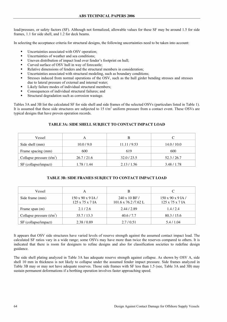
load/pressure, or safety factors (SF). Although not formalized, allowable values for these SF may be around 1.5 for side frames, 1.1 for side shell, and 1.2 for deck beams. In selecting the acceptance criteria for structural designs, the following uncertainties need to be taken into account:
Uncertainties associated with OSV operation; Uncertainties of weather and sea conditions; Uneven distribution of impact load over fender’s footprint on hull; Curved surface of OSV hull in way of forecastle; Relative dimensions of fenders and the structural members in consideration; Uncertainties associated with structural modeling, such as boundary conditions; Stresses induced from normal operations of the OSV, such as the hull girder bending stresses and stresses
due to lateral pressure of external and internal water; Likely failure modes of individual structural members; Consequences of individual structural failures; and Structural degradation such as corrosion wastage.
Tables 3A and 3B list the calculated SF for side shell and side frames of the selected OSVs (particulars listed in Table 1). It is assumed that these side structures are subjected to 15 t/m2 uniform pressure from a contact event. These OSVs are typical designs that have proven operation records.
TABLE 3A: SIDE SHELL SUBJECT TO CONTACT IMPACT LOAD
Vessel A B C
Side shell (mm) 10.0 / 9.0 11.11 / 9.53 14.0 / 10.0
Frame spacing (mm) 600 619 600
Collapse pressure (t/m2) 26.7 / 21.6 32.0 / 23.5 52.3 / 26.7
SF (collapse/impact) 1.78 / 1.44 2.13 / 1.56 3.48 / 1.78
TABLE 3B: SIDE FRAMES SUBJECT TO CONTACT IMPACT LOAD
Vessel A B C
Side frame (mm) 150 x 90 x 9 IA / 125 x 75 x 7 IA
240 x 10 BF / 101.6 x 76.2 /7.62 L
150 x 90 x 9 IA / 125 x 75 x 7 IA
Frame span (m) 2.1 / 2.6 2.44 / 2.89 1.4 / 2.4
Collapse pressure (t/m2) 35.7 / 13.3 40.6 / 7.7 80.3 / 15.6
SF (collapse/impact) 2.38 / 0.89 2.7 / 0.51 5.4 / 1.04 It appears that OSV side structures have varied levels of reserve strength against the assumed contact impact load. The calculated SF ratios vary in a wide range; some OSVs may have more than twice the reserves compared to others. It is indicated that there is room for designers to refine designs and also for classification societies to redefine design guidance. The side shell plating analyzed in Table 3A has adequate reserve strength against collapse. As shown by OSV A, side shell 10 mm in thickness is not likely to collapse under the assumed fender impact pressure. Side frames analyzed in Table 3B may or may not have adequate reserves. Those side frames with SF less than 1.5 (see, Table 3A and 3B) may sustain permanent deformations if a berthing operation involves faster approaching speed.
ABS TECHNICAL PAPERS 2006
Design Against Contact Damage for Offshore Supply Vessels 65
MITIGATION OF CONTACT DAMAGE Preventing or mitigating contact damage risks can be achieved through: 1) reducing the likelihood of an unwanted contact from occurring; 2) mitigating and minimizing damage to the OSV hulls if an un-intended contact takes place, or both. Reducing the likelihood of an unwanted severe contact can be achieved through: 1) better manning the OSV through training and education of crew, 2) establishing operation procedures and guidance, 3) installing advanced vessel maneuvering and control systems (e.g., dynamic positioning systems, controllable pitch propellers, azimuth thrusters, bow/side thrusters). In addition to the above remedies taken by OSV operations, installing and properly maintaining stronger (larger) marine rubber fenders on rig/installations and/or OSVs in locations where there may be exposed contact impacts are options for mitigating and minimizing contact damage for both the OSV and rig/installations. Structural reinforcement against the anticipated impact load is aimed at providing strength reserve against a certain level of impact energy that is normally expected from a routine operation. Normally, half-split steel pipes are installed as fixed structures at the deck levels of OSV so that impact load are distributed to a wider extent, and/or the main hull structures are not directly exposed to the impacts load. These half-split steel pipes, sometimes called “fenders”, can also absorb impact energy. Usually, this reinforcement applies to some specified location, as OSVs usually come alongside and berth at designated locations. DESIGN STANDARD DEVELOPMENT The design criteria for contact damage should address:
Design berthing condition, including maximum kinetic energy; Areas of OSV hull for design against contact damage; Design load and considered marine rubber fenders; Scantling criteria of structural members (side beam, web frames, deck beams); Design of structural arrangements and details such as brackets; and Options for mitigating contact damage.
It is expected that during normal berthing operations that follow the industry standards, an OSV will not suffer severe contact damage that may compromise structural integrity or incur unscheduled repairs. Further studies are needed to more clearly define the limits to kinetic energy in a normal or good berthing operation. Cooperation among OSV operators, marine fender manufactures, OSV builders and classification societies are needed. Focus of further development should be placed on approach speed, angle, added mass, extents of impact pressure, potential contact impact locations, and so on. Probabilistic presentation of the contact energy needs to be developed with the inputs from all industry partners. The derived PDF (Probability Density Functions) will create a solid base for the rational approach in defining the design load and will explicitly quantify the safety level in the design rules. The scantling requirements may be cast for the following structural members: side shell, side frames, deck beams, web frames, deck plates and side stringers. The half-split steel pipe fenders installed at deck levels are not discussed here, but should also be part of the design criteria. CONCLUSIONS This paper presents a systematic approach to address the contact damage in structural designs. It proposes a regulated framework that can be applied in design and risk assessment schemes. The focus is placed on scenarios of a contact event, impact load and pressure, structural responses and acceptance criteria. As opposed to the previous study on steel-to-steel contact (Wang and Otsubo 1999), the research presented in this paper reflects more marine practice and the satisfactory performance of fenders, rubber and pneumatic, which are considered as directly impacting OSV’s hull structures. It reveals that the impact pressure of 15 t/m2, independent of OSV sizes, can be used for structural design of OSV hulls when appropriate fender arrangements are provided on offshore installations.

ABS TECHNICAL PAPERS 2006
66 Design Against Contact Damage for Offshore Supply Vessels
ACKNOWLEDGEMENT The authors appreciate the valuable comments from Melvin Antony. The authors are indebted to J. Speed for editing the manuscript. REFERENCES
ABS (1998). Guide for Shipbuilding and Repair Quality Standard for Hull Structures during Construction. American Bureau of Shipping, 1998.
ABS (2005). Guidance Notes on Ice Class, American Bureau of Shipping, Houston TX.
Bridgestone (2000). Cell Fender Series, Bridgestone Corporation, Tokyo, Japan.
Gaythwaite (1990). Design Of Marine Facilities For Berthing, Mooring And Repair Of Vessels, Van Nostrand Reinhold, NY.
Ghose, D. J., Nappi, N. S. and Wiernicki, C. J. (1994). “Residual strength of damaged marine structures,” SSC-381, NTIS#PB95-185419, Sept. 1994, Ship Structures Committee.
ISSC (2006). ISSC Committee V.1 Collision and Grounding, www.issc-collisiongrounding.org, 16th International Ship and Offshore Structures Congress (ISSC), Southampton, UK.
Jones, N. (1989). Structural Impact, Cambridge University, Cambridge, UK.
OCIMF (1997). Ship to Ship Transfer Guide (Petroleum). Oil Company International Marine Forum.
Pedersen P.T. and Zhang, S. (1998). “On impact mechanics in ship collisions.” Marine Structures, 11: 429-449.
Paik J.K., Chung J.Y., Choe I.H., Thayamballi A.K., Pedersen P.T., and Wang G. (1999). “On rational design of double hull tanker structures against collision.” Transactions of SNAME, 107, 1999.
Wang G. and Ohtsubo H. (1999). “Impact load of a supply vessel.” 9th International Offshore and Polar Engineering Conference & Exhibition. Brest, France, IV, 463-471.
Wang G. (2002) “Some recent studies on plastic behavior of plates subjected to very large load.” Journal of Ocean Mechanics and Arctic Engineering, ASME.
Wang G., Spencer J. and Chen, Y.J. (2002a). “Assessment of ship’s performance in accidents”. Marine Structures, 15, 313-333.
Wang G., Tang S. and Shin Y. (2002b). “Direct calculation approach and design criteria for wave slamming of an FPSO bow.” International Journal of Offshore and Polar Engineering. 12 (4), 297-304.
Wang G., Jiang D. and Shin Y. (2003). “Collision and contact damage risks to FPSO.” Offshore Technology Conference, Houston, TX.
Wang, G. and Wiernicki, C. J. (2004). “Using nonlinear finite element method to design ship structures for ice load.” Transactions of SNAME, 112.
Wang, G, Basu, R. and Chavda, D (2005). “Rationalizing design of ice strengthening side structures.” International Congress of International Maritime Association of the Mediterranean (IMAM 2005), Lisboa, Portugal, 26 – 30 September 2005.
Wang, G., Liu, S. and Riska, K. (2006). “Recent advances on structural design of ice-strengthened vessels.” ICETECH, Banff, Canada.
Wu F., Spong R. and Wang G. (2004). “Verification of numerical simulation approach for ship collision problem.” 3rd International Conference on Collision and Grounding of Ships (ICCGS). 25-27 October 2004, Tokyo, Japan.
YRC (2005). Yokohama Floating Fenders Pneumatic 50 & 80, Catalog No. CN-0303S-02E, The Yokohama Rubber Company, Ltd, Tokyo, Japan.