Flaps with Wavy Leading Edges for Robust Performance agains Upstream Trailing Vortices
Upload
sabina-montgomeryCategory
view
225download
1
Design Agains FatigueDesign Agains Fatigue- part Fatigue Endurance Prediction- part Fatigue Endurance Prediction
Milan Růžička
CTU in Prague, Faculty of Mechanical Engineering DAF Page 2
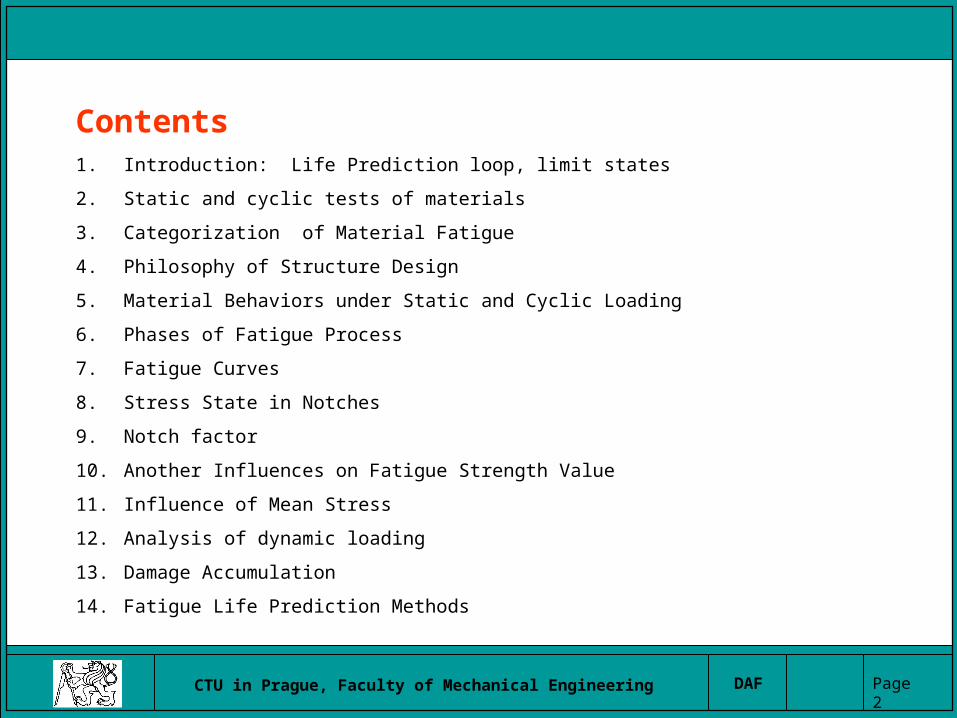
Contents1. Introduction: Life Prediction loop, limit states
2. Static and cyclic tests of materials
3. Categorization of Material Fatigue
4. Philosophy of Structure Design
5. Material Behaviors under Static and Cyclic Loading
6. Phases of Fatigue Process
7. Fatigue Curves
8. Stress State in Notches
9. Notch factor
10. Another Influences on Fatigue Strength Value
11. Influence of Mean Stress
12. Analysis of dynamic loading
13. Damage Accumulation
14. Fatigue Life Prediction Methods

CTU in Prague, Faculty of Mechanical Engineering DAF Page 3
Fatigue life prediction loop
Pre-project phase
Design phase
Prototype verification
Real service
Computational work
Experimental work
DATABASE
Fatigue curves
Loading spectraFinding of
critical places
Strains and stresscalculations
Fatigue life verification and recalculation
Service loading and critical places verification
Fatigue life prediction

CTU in Prague, Faculty of Mechanical Engineering DAF Page 4
CAX- analysis
Elastic, PlasticCreep
Analysis of Fatigue Damage
MISES VALUE+3.67 E+00
+2.83 E+02+1.70 E+02
+3.36 E+02+4.19 E+02+5.02 E+02
+5.85 E+02+6.68 E+02+7.51 E+02+8.34 E+02
+8.67 E+01
+9.17 E+02+1.00 E+03+1.63 E+03
1
2
3
Analysisof limit
state
CADmodel
FEManalysis

CTU in Prague, Faculty of Mechanical Engineering DAF Page 5
Limit states
Limit states
1. L.S. of Strength• Static Strength (Ductile
Fracture)
• Plasticity, Plast. Adaptation
• Stability, Buckling
• Brittle Fracture
• Creep (Creep Fracture)
• Low-, High-Cycle Fatigue
• Temperature Shock
• Fatigue + Creep Interaction
2. L.S. of Functional Capability
• Elastic and Plastic Deformation
• Impact Damage
• Dynamic Response
• Wearing
• Corrosion

CTU in Prague, Faculty of Mechanical Engineering DAF Page 6
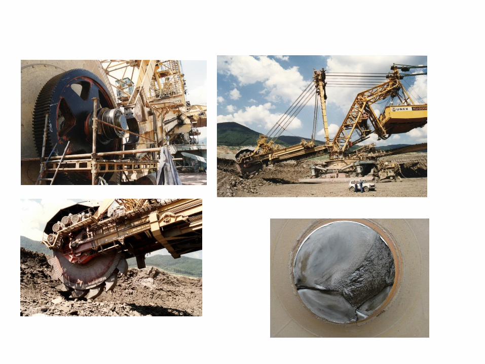
Brittle fracture and fatigue damage of large structures

CTU in Prague, Faculty of Mechanical Engineering DAF Page 7
Brittle fracture and fatigue damage of large structures
Takona bridge The Latchford Bridge Failure (2003 )
CTU in Prague, Faculty of Mechanical Engineering DAF Page 9
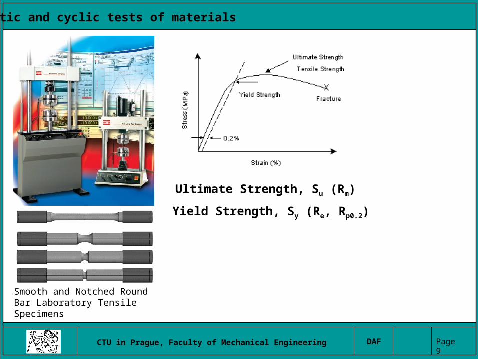
Static and cyclic tests of materials
Smooth and Notched Round Bar Laboratory Tensile Specimens
Ultimate Strength, Su (Rm)
Yield Strength, Sy (Re, Rp0.2)

CTU in Prague, Faculty of Mechanical Engineering DAF Page 10
Material behavior under static and cyclic loading
0
100
200
300
400
500
600
700
800
0 0.002 0.004 , e [1]
0
100
200
300
400
500
600
700
800
0 0.2 0.4 0.6 0.8 1 , e [1]
, S
[MP
a]
Skutečný tah.diagram
Konvenční tah.diagram
f
Rm
Re
f
el
ll
l
l
eSl
llS
l
lS
A
AS
A
F
1ln1lnln
11
0
0
0
0
0
0
0
npK
K - monotonic strength hardening koeff.n - monotonic strength hardening exponentp - plastic strain
Engineering stress (Lagrange stress) S = F / A0,
Engineering strain of measured specimen leght e = (l - l0) / l0 force recomputation at the instantaneous section
True stress (Cauchy stress) = F / A
True (logaritmic) strain = ln(l / l0).
True stress-strain diagram
Engineering stress-strain diagram
Aproximation of the true stress-strain diagram
CTU in Prague, Faculty of Mechanical Engineering DAF Page 11
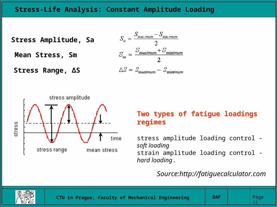
Stress-Life Analysis: Constant Amplitude Loading
Stress Amplitude, Sa
Mean Stress, Sm
Stress Range, ΔS
Two types of fatigue loadings regimes
stress amplitude loading control - soft loadingstrain amplitude loading control - hard loading.
Source:http://fatiguecalculator.com

CTU in Prague, Faculty of Mechanical Engineering DAF Page 12
Different mean stress
CTU in Prague, Faculty of Mechanical Engineering DAF Page 13
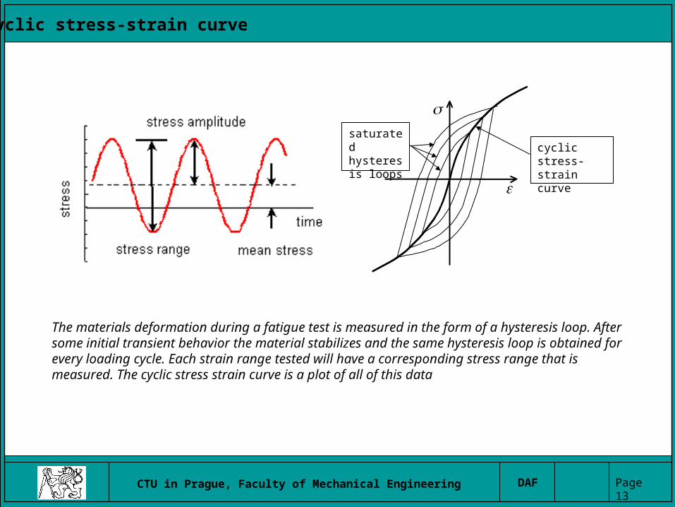
Cyclic stress-strain curve
saturated hysteresis loops
cyclic stress-strain curve
The materials deformation during a fatigue test is measured in the form of a hysteresis loop. After some initial transient behavior the material stabilizes and the same hysteresis loop is obtained for every loading cycle. Each strain range tested will have a corresponding stress range that is measured. The cyclic stress strain curve is a plot of all of this data

CTU in Prague, Faculty of Mechanical Engineering DAF Page 14
Hysteresis loop
-300
-200
-100
0
100
200
300
-0.01 -0.005 0 0.005 0.01
[1]
[M
Pa
]
a
ap
ae
a
napa K
naa
apaea KE
1
K’ - cyclic strain hardening koeff.n’ - cyclic strain hardening exponentE - Young’s modulus of elasticity (tension)
Aproximation of the cyclic stress-strain curve
CTU in Prague, Faculty of Mechanical Engineering DAF Page 15
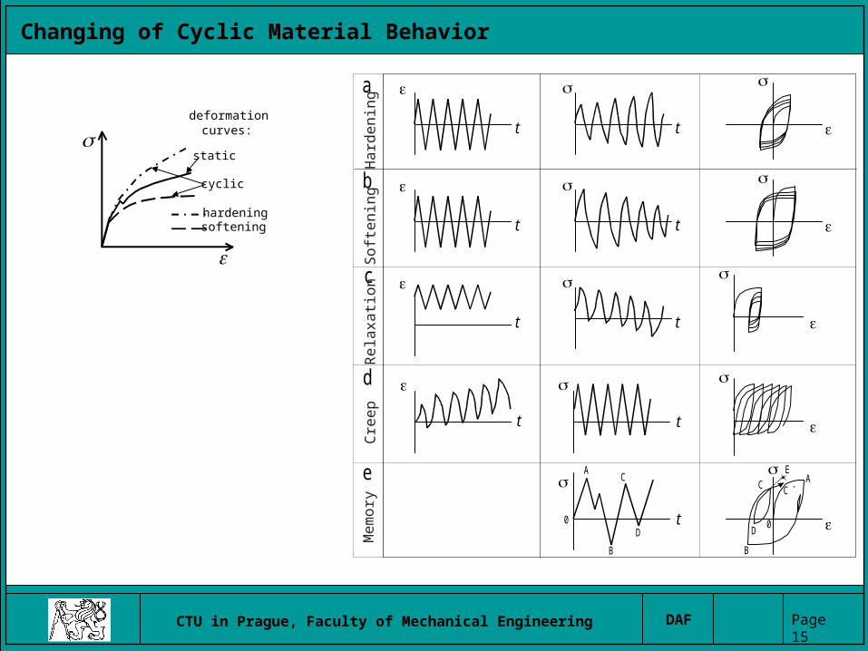
Changing of Cyclic Material Behavior
t
t
t
t
t t
t
t
t
a
b
c
d
e
0
A
B
C
DD
C
B
A
0
C´
E
Re
laxa
tion
Ha
rde
nin
gS
oft
en
ing
Cre
ep
Me
mo
ry
hardening
softening
deformationcurves:
cyclic
static

CTU in Prague, Faculty of Mechanical Engineering DAF Page 16
Fatigue Testing Machines http://www.kuleuven.ac.be

CTU in Prague, Faculty of Mechanical Engineering DAF Page 17
Fatigue Testing Machines

CTU in Prague, Faculty of Mechanical Engineering DAF Page 18
Stress- Life Curves
www.tu-berlin.de
www.ncode.com
CTU in Prague, Faculty of Mechanical Engineering DAF Page 19
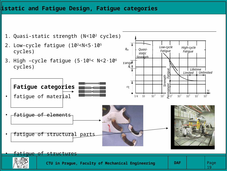
Quasistatic and Fatigue Design, Fatigue categories
Rm
range Re
C
Quasi-static Strength
Low-cycle Fatigue
High-cycle Fatigue
Lifetime Limited Unlimited
Stre
ngth
Per
man
ent
Fat
igue
1. Quasi-static strength (N<102 cycles)
2. Low-cycle fatigue (102<N<5·105 cycles)
3. High –cycle fatigue (5·105< N<2·106 cycles)
Fatigue categories
• fatigue of material
• fatigue of elements
• fatigue of structural parts
• fatigue of structures
CTU in Prague, Faculty of Mechanical Engineering DAF Page 20
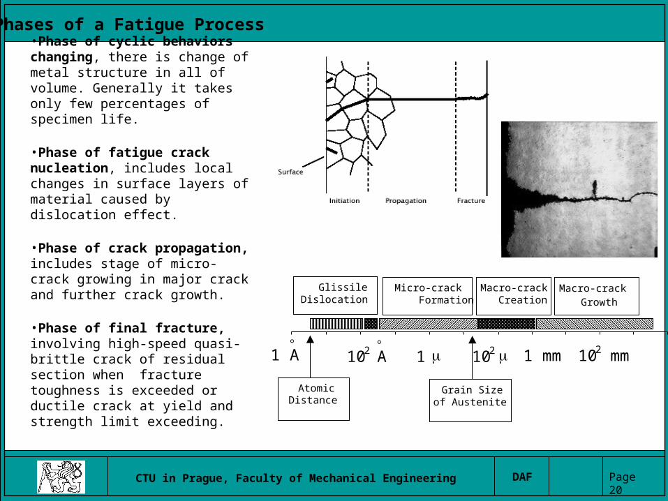
Phases of a Fatigue Process
•Phase of cyclic behaviors changing, there is change of metal structure in all of volume. Generally it takes only few percentages of specimen life.
•Phase of fatigue crack nucleation, includes local changes in surface layers of material caused by dislocation effect.
•Phase of crack propagation, includes stage of micro-crack growing in major crack and further crack growth.
•Phase of final fracture, involving high-speed quasi-brittle crack of residual section when fracture toughness is exceeded or ductile crack at yield and strength limit exceeding.
1 A
102 A
1 102 1 mm 102 mm
AtomicDistance
Grain Sizeof Austenite
Micro-crack Formation
GlissileDislocation
Macro-crack Creation
Macro-crack Growth
CTU in Prague, Faculty of Mechanical Engineering DAF Page 21
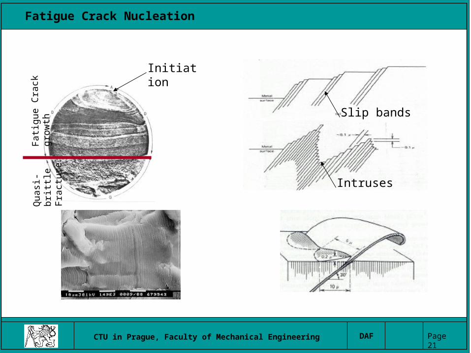
Fatigue Crack Nucleation
Fat
igue
Cra
ck g
row
thQ
uasi
-br
ittl
e F
ract
ure
Intruses
Slip bands
Initiation

CTU in Prague, Faculty of Mechanical Engineering DAF Page 22
Fracture surfaces
CTU in Prague, Faculty of Mechanical Engineering DAF Page 23
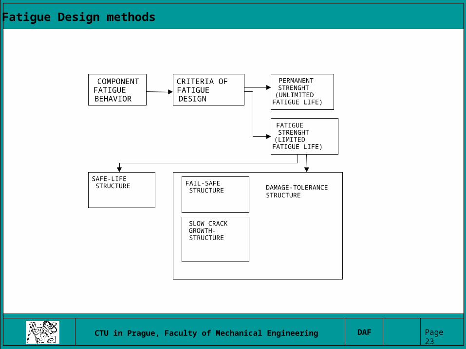
Fatigue Design methods
COMPONENTFATIGUEBEHAVIOR
CRITERIA OFFATIGUE DESIGN
PERMANENTSTRENGHT(UNLIMITEDFATIGUE LIFE)
FATIGUESTRENGHT(LIMITEDFATIGUE LIFE)
SAFE-LIFESTRUCTURE
FAIL-SAFESTRUCTURE DAMAGE-TOLERANCE
STRUCTURE
SLOW CRACKGROWTH-STRUCTURE

CTU in Prague, Faculty of Mechanical Engineering DAF Page 24
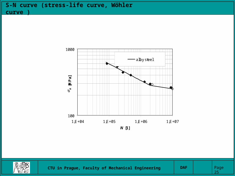
S-N curve (stress-life curve, Wöhler curve )
100
1000
1,E+04 1,E+05 1,E+06 1,E+07
N [1]
a [
MP
a]
100
1000
1,E+04 1,E+05 1,E+06 1,E+07
N [1]
a [
MP
a]
100
1000
1,E+04 1,E+05 1,E+06 1,E+07
N [1]
a [
MP
a]
structural steel
• stress amplitude loading control - soft loading• R=const., or Sm=const.•Enduramce limit, Fatigue limit SFL
•Probability of fracture P [%]
Fatigue limit
CTU in Prague, Faculty of Mechanical Engineering DAF Page 25
100
1000
1,E+04 1,E+05 1,E+06 1,E+07
N [1]
a [
MP
a]
100
1000
1,E+04 1,E+05 1,E+06 1,E+07
N [1]
a
[M
Pa
]
alloy steel
S-N curve (stress-life curve, Wöhler curve )
CTU in Prague, Faculty of Mechanical Engineering DAF Page 26
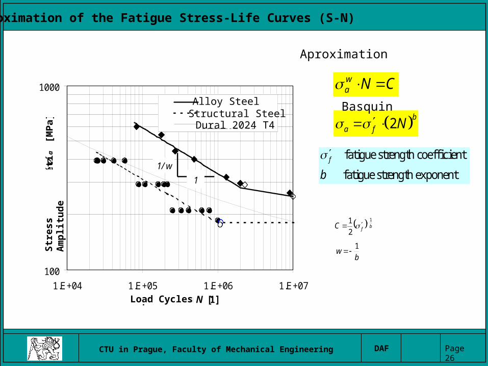
Aproximation of the Fatigue Stress-Life Curves (S-N)
100
1000
1.E+04 1.E+05 1.E+06 1.E+07počet kmitů N [1]
amp
litu
da
nap
ětí
a [M
Pa]
ocel slitinováocel konstrukčnídural 2024 T3
1
1/ w
CNwa
2b
a f N
bfC1
2
1
bw
1
Alloy SteelStructural SteelDural 2024 T4
Load Cycles
Str
ess
Am
pli
tud
eAproximation
Basquin
fatigue strength coefficient
fatigue strength exponent
f
b

CTU in Prague, Faculty of Mechanical Engineering DAF Page 27
Strain-Life Curve (-N), Manson-Coffin‘s curve
0.0001
0.001
0.01
0.1
1
1.E+00 1.E+01 1.E+02 1.E+03 1.E+04 1.E+05 1.E+06 1.E+07
počet půlkmitů 2N [1]
ampl
ituda
pom
. def
orm
ace
a [1
]
ae
ap
a
f '
f ' /E
b
c
1
1
cf
bfapaea NN
E22
6,06,012,05,32 NNE
Rf
ma
general tangent method
Number of Half-Cycles
Str
ain
Am
pli
tud
e
Aproximation
fatigue ductility coefficient
fatigue ductility exponent
f
c
CTU in Prague, Faculty of Mechanical Engineering DAF Page 28
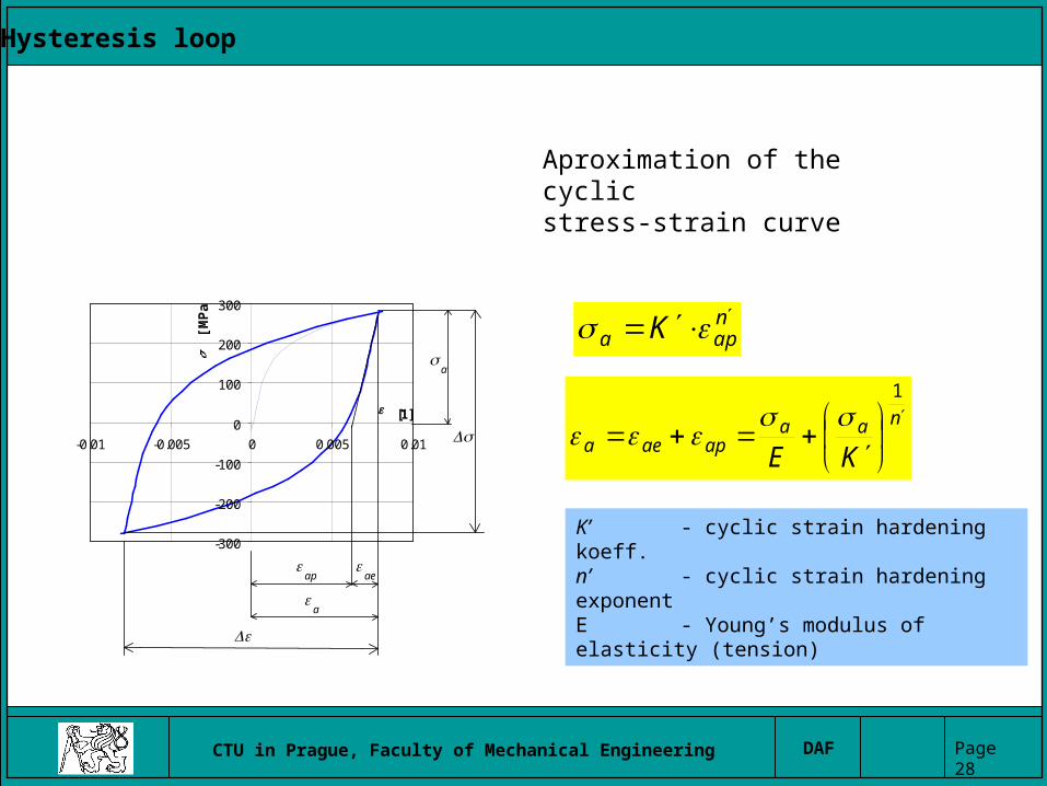
Hysteresis loop
-300
-200
-100
0
100
200
300
-0.01 -0.005 0 0.005 0.01
[1]
[M
Pa
]
a
ap
ae
a
napa K
naaapaea KE
1
K’ - cyclic strain hardening koeff.n’ - cyclic strain hardening exponentE - Young’s modulus of elasticity (tension)
Aproximation of the cyclic stress-strain curve
CTU in Prague, Faculty of Mechanical Engineering DAF Page 29
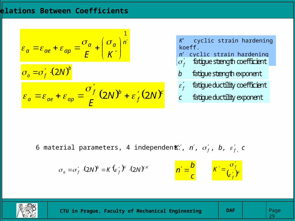
Relations Between Coefficients
naaapaea KE
1
K’ cyclic strain hardening koeff.n’ cyclic strain hardening exponent
2b
a f N fatigue strength coefficient
fatigue strength exponent
f
b
cf
bfapaea NN
E22
fatigue ductility coefficient
fatigue ductility exponent
f
c
ncnf
bfa NKN
22 nf
fK
c
bn
cbnK ff ,,,,, 6 material parameters, 4 independent:
CTU in Prague, Faculty of Mechanical Engineering DAF Page 30
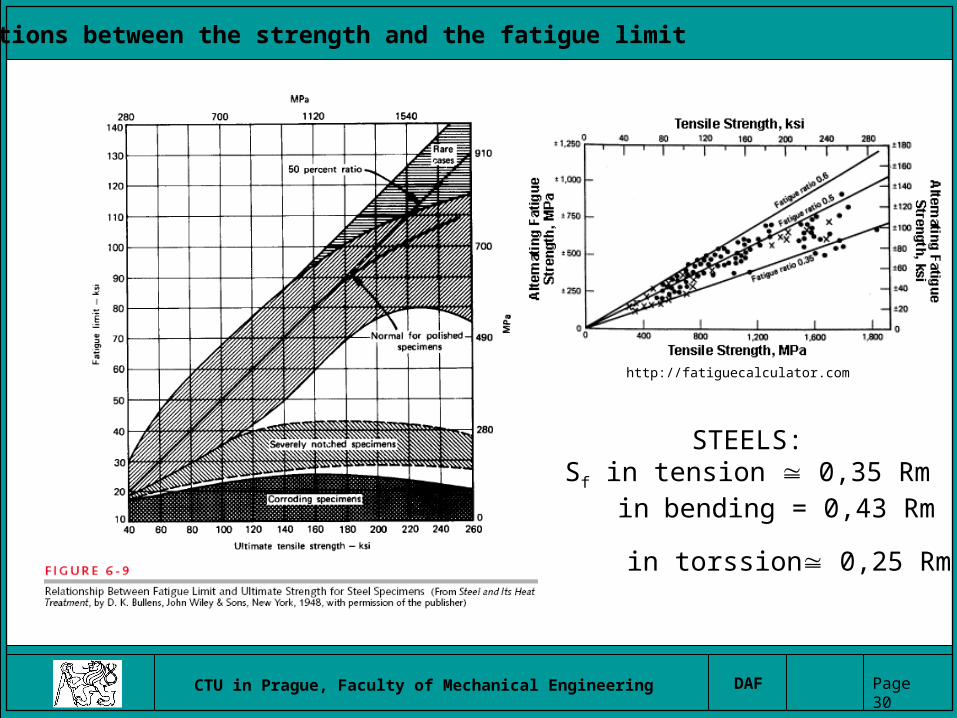
Relations between the strength and the fatigue limit
STEELS:Sf in tension 0,35 Rm in bending = 0,43 Rm
in torssion 0,25 Rm .
http://fatiguecalculator.com

CTU in Prague, Faculty of Mechanical Engineering DAF Page 31
Example http://fatiguecalculator.com
CTU in Prague, Faculty of Mechanical Engineering DAF Page 32
Questions and problems I
.
1. What is difference between static design and fatigue design of structures?
2. What are typical attributes for low cycle fatigue and for high cycle fatigue?
3. Draw a hysteresis loop and describe on it elastic and plastic part of strain.
4. Specify phases of damage and fatigue progress in metals. 5. What is main difference between safe-life and fail-safe design
philosophy?6. What are main attributes of the damage tolerance design
philosophy?7. Define the fatigue limit of a given material8. What type of fatigue curve describes high cycle fatigue primary?
Draw this curve.9. What type of fatigue curve describes low cycle fatigue? Draw this
curve.10.Could be fatigue limit higher as yield strength?11.How many percent of ultimate strength could you predict the fatigue
limit of carbon steel?

CTU in Prague, Faculty of Mechanical Engineering DAF Page 33
Questions and problems I
.
1. Example 1: Approximation of a stress amplitude is napa K . Derive equation for
the total strain amplitude of a hysteresis loop apaea ?
2. Example 2: Approximation of the fatigue curve is CNwa or b
fa N2 .
Derive relations between parameters .,,, wbC f
3. Example 3: There are 6 material fatigue parameters cbnK ff ,,,,, , only
are 4 independent. Derive relations between these parameters. 4. Example 4: There is special number of cycles ( tN ) in the Strain-life curve,
where apae . Derive equation to calculate this number tN .