Design a Heat Pump that can Deliver Water at Temperatures ...
46
Indiana University - Purdue University Fort Wayne Department of Engineering (ME 487 - ME 488) Capstone Senior Design Project Report #2 Project Title: Design of a Heat Pump that can Deliver Water at Temperatures Above 140F Degrees Team Members: Ashley Coulson Jim Frauhiger Patrick Stone Mark Wilmes Faculty Advisor: Dr. Hosni Abu-Mulaweh Date: December 8, 2008
Transcript of Design a Heat Pump that can Deliver Water at Temperatures ...

Indiana University - Purdue University Fort Wayne
Department of Engineering
(ME 487 - ME 488)
Capstone Senior Design Project
Report #2
Project Title: Design of a Heat Pump that can Deliver Water at Temperatures Above
140F Degrees
Team Members: Ashley Coulson
Jim Frauhiger
Patrick Stone
Mark Wilmes
Faculty Advisor: Dr. Hosni Abu-Mulaweh
Date: December 8, 2008
2
Table of Contents
Acknowledgements ....................................................................................................................... 3
Abstract / Summary ...................................................................................................................... 5
Section I: Design Parameters ...................................................................................................... 8
Description .................................................................................................................................. 9
Parameters ................................................................................................................................. 10
Summary ................................................................................................................................... 11
Section II: Build Procedure....................................................................................................... 12
Purpose ...................................................................................................................................... 13
Abstract ..................................................................................................................................... 13
Objectives .................................................................................................................................. 13
Setup and Procedure .................................................................................................................. 13
Procedure ................................................................................................................................... 14
Section III: Test Procedure ....................................................................................................... 15
Description ................................................................................................................................ 16
Component Selection ................................................................................................................ 16
Modeling ................................................................................................................................... 16
Test Procedure ........................................................................................................................... 17
Section IV: Evaluation and Recommendations ....................................................................... 20
Description ................................................................................................................................ 21
Results Analysis ........................................................................................................................ 21
Recommendations ..................................................................................................................... 21
Conclusion ................................................................................................................................. 24
Cost Analysis / Estimation.......................................................................................................... 25
Objective ................................................................................................................................... 26
Procedure ................................................................................................................................... 26
Results ....................................................................................................................................... 26
Geothermal Heat Pump ......................................................................................................... 26
#2 Fuel Oil Boiler .................................................................................................................. 27
Natural Gas Boiler ................................................................................................................. 27
Propane Boiler ....................................................................................................................... 27
Conclusion ................................................................................................................................. 28
Conclusion ................................................................................................................................... 29
Appendix A: Step by Step Pictorial of Heat Pump Build....................................................... 31
Appendix B: WaterFurnace International Test Data Sheet .................................................. 34
Appendix C: EES Example Code ............................................................................................. 35
EES Program for R-134a Analysis............................................................................................ 35
EES Results (Output) ................................................................................................................ 45

3
Acknowledgements
4
Acknowledgements
The design team would like to acknowledge and thank the following individuals and companies
for their support or guidance during the design process of the heat pump system.
Dr. Hosni Abu-Mulaweh Primary Project Advisor
Dr. Donald Mueller, Jr. Secondary Project Advisor
Mr. Christopher Manz Sponsor Company Contact
Mr. Mark Adams Sponsor Company Contact
WaterFurnace International Sponsor Company

5
Abstract / Summary

6
Abstract / Summary
WaterFurnace International, a Fort Wayne, Indiana based company specializing in geothermal
heating systems is sponsoring the design of a water to water heat pump system which is able to
deliver water at temperatures above 140°F. Many parameters of the heat pump system were
defined by WaterFurnace International. For instance, the coefficient of performance had to be
greater than or equal to 2, the capacity of the system had to be 3 tons, or 30,000 BTU/hr, and the
refrigerant choice had to be environmentally friendly.
A standard vapor compression cycle was chosen for the design. This cycle includes a
compressor, a heat exchanger for condensing the refrigerant, an expansion valve, and another
heat exchanger for evaporating the refrigerant. This cycle was chosen due to its relative
simplicity of components and its cost effectiveness when compared to other more complicated
cycles, such as cascading vapor compression cycles. The methodology for designing this heat
pump follows an iterative design process which includes concept generation and analysis,
component selection, and a detailed analysis model of the finalized design. The design process
includes using ideas and methods learned in thermal science classes including thermodynamics,
heat transfer, and fluid mechanics.
Given the required information, the senior design team defined the problem by collecting and
confirming all the requirement and constraints given by WaterFurnace International. The team
then generated conceptual designs capable of satisfying the specified problem. The conceptual
designs were generated through research and brainstorming techniques. In this stage, many
refrigerants were considered for use in the design. A comparative study of the refrigerants was
generated. This study showed the saturation pressure and the corresponding saturation
temperature of all the refrigerants that were considered. From this, a plot was generated. In this
plot, many refrigerants were deemed incapable of satisfying the design requirements. The
refrigerants that appeared to be capable of satisfying the design requirements were used for the
conceptual design. Several compressor types were also considered in the conceptual design
phase. Research was conducted that identified the strengths and weaknesses of each type of
compressor. Two types of heat exchangers were also considered. Research was performed to
identify the best type of heat exchanger to use for the design.
The conceptual designs were then evaluated to reveal their strengths and weaknesses. A
simplified model of the cycle was created in Engineering Equation Solver (EES). This model
allowed for the comparison of the selected refrigerants, so the best ones could be selected. This
comparison showed that only a few refrigerants met all the requirements. By evaluating the
conceptual designs, the best combinations of the each component were combined to form the
detailed design. For the detailed design, the chosen solution met all of the requirements given by
WaterFurnace International. After all the concepts were evaluated, the primary design was
chosen to be R134a with a 3 ton scroll compressor and 3 ton flat plate heat exchanger. The
secondary design was chosen to be R426a with a 3 ton scroll compressor and 3 ton flat plate heat
exchanger. Lastly, the senior design team generated a parametric table to be used when
simulating and improving the system during the testing phase of the project.
7
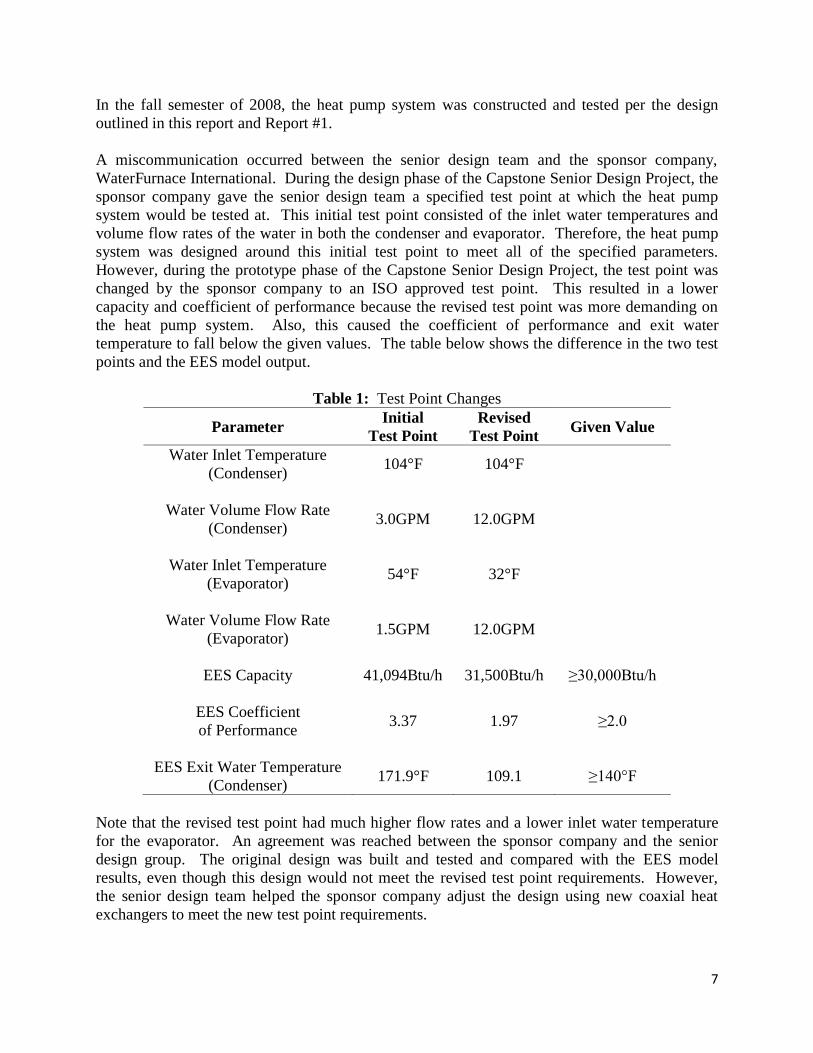
In the fall semester of 2008, the heat pump system was constructed and tested per the design
outlined in this report and Report #1.
A miscommunication occurred between the senior design team and the sponsor company,
WaterFurnace International. During the design phase of the Capstone Senior Design Project, the
sponsor company gave the senior design team a specified test point at which the heat pump
system would be tested at. This initial test point consisted of the inlet water temperatures and
volume flow rates of the water in both the condenser and evaporator. Therefore, the heat pump
system was designed around this initial test point to meet all of the specified parameters.
However, during the prototype phase of the Capstone Senior Design Project, the test point was
changed by the sponsor company to an ISO approved test point. This resulted in a lower
capacity and coefficient of performance because the revised test point was more demanding on
the heat pump system. Also, this caused the coefficient of performance and exit water
temperature to fall below the given values. The table below shows the difference in the two test
points and the EES model output.
Table 1: Test Point Changes
Parameter Initial
Test Point
Revised
Test Point Given Value
Water Inlet Temperature
(Condenser) 104°F 104°F
Water Volume Flow Rate
(Condenser) 3.0GPM 12.0GPM
Water Inlet Temperature
(Evaporator) 54°F 32°F
Water Volume Flow Rate
(Evaporator) 1.5GPM 12.0GPM
EES Capacity 41,094Btu/h 31,500Btu/h ≥30,000Btu/h
EES Coefficient
of Performance 3.37 1.97 ≥2.0
EES Exit Water Temperature
(Condenser) 171.9°F 109.1 ≥140°F
Note that the revised test point had much higher flow rates and a lower inlet water temperature
for the evaporator. An agreement was reached between the sponsor company and the senior
design group. The original design was built and tested and compared with the EES model
results, even though this design would not meet the revised test point requirements. However,
the senior design team helped the sponsor company adjust the design using new coaxial heat
exchangers to meet the new test point requirements.

8
Section I: Design Parameters
9
Section I: Design Parameters
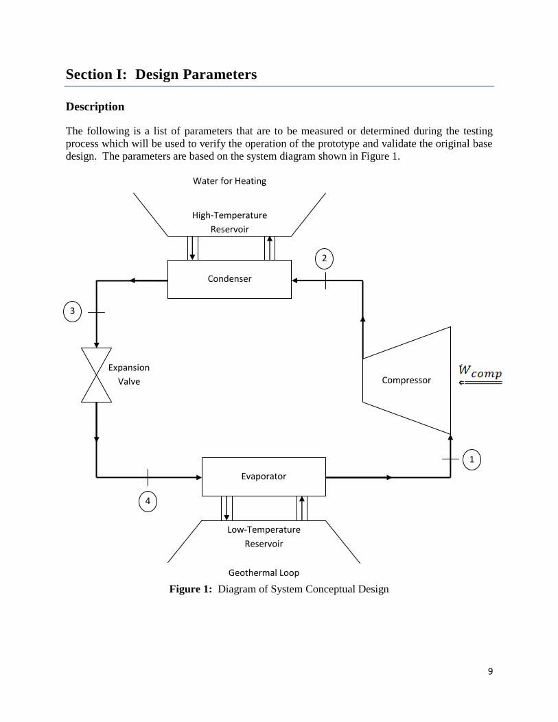
Description
The following is a list of parameters that are to be measured or determined during the testing
process which will be used to verify the operation of the prototype and validate the original base
design. The parameters are based on the system diagram shown in Figure 1.
Figure 1: Diagram of System Conceptual Design
Low-Temperature
Reservoir
Geothermal Loop
Compressor
1
Evaporator
4
High-Temperature
Reservoir
Water for Heating
Condenser
2
3
Expansion
Valve
10
Parameters
Water Temperature – Entering the Condenser – From High Temperature Reservoir
The water temperature entering the condenser is important because it will be used in
calculating the effectiveness of the heat exchanger and is the returning water temperature.
Water Temperature – Exiting the Condenser – To High Temperature Reservoir
The water temperature exiting the condenser is the goal for the system. The entire
purpose of the heat pump system is to deliver water at temperatures above 140°F for the
heating system. This value was given by the sponsor company, WaterFurnace
International.
Refrigerant Temperature – Exiting the Compressor – State 2
The refrigerant temperature exiting the compressor and entering the condenser is the
second most important parameter of the entire system. It directly affects the water
temperature exiting the condenser. This value was designed to be between 150°F and
175°F.
Refrigerant Temperature – Exiting the Condenser – State 3
The refrigerant temperature exiting the condenser should be subcooled 10°F. The
condensing temperature was specified as 120°F by the sponsor company, WaterFurnace
International, and the pressure at this point was calculated to be 185.65 psia.
Refrigerant Temperature – Exiting the Evaporator – State 1
The refrigerant temperature exiting the evaporator should be superheated 10°F. The
evaporating temperature was given to be 25°F by the sponsor company, WaterFurnace
International and the pressure at this point was calculated 34.95 psia.
Water Temperature – Entering the Evaporator – From Low Temperature Reservoir (Geothermal
Loop)
The water temperature entering the evaporator affects the amount of heat that will be
transferred from the water to the refrigerant. This value was averaged to be
approximately 54°F given by the sponsor company, WaterFurnace International.
Refrigerant Pressure – State 1 and State 2 – Entering and Exiting the Compressor
The refrigerant pressure will be measured at state 1 and state 2 so that the system’s
pressure ratio can be calculated. Also, the maximum pressure in the system is at state 2
and must not exceed the 600 psia maximum predetermined by the sponsor company,
WaterFurnace International.
11
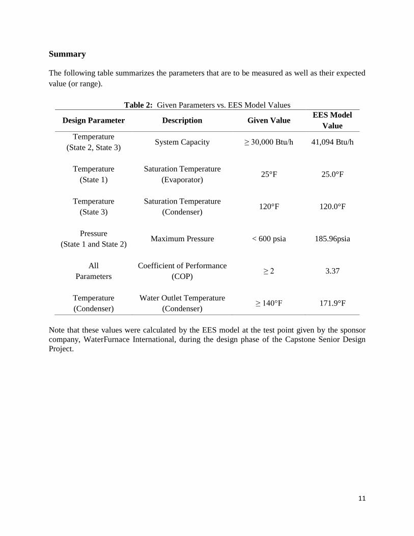
Summary
The following table summarizes the parameters that are to be measured as well as their expected
value (or range).
Table 2: Given Parameters vs. EES Model Values
Design Parameter Description Given Value EES Model
Value
Temperature
(State 2, State 3) System Capacity ≥ 30,000 Btu/h 41,094 Btu/h
Temperature
(State 1)
Saturation Temperature
(Evaporator) 25°F 25.0°F
Temperature
(State 3)
Saturation Temperature
(Condenser) 120°F 120.0°F
Pressure
(State 1 and State 2) Maximum Pressure < 600 psia 185.96psia
All
Parameters
Coefficient of Performance
(COP) ≥ 2 3.37
Temperature
(Condenser)
Water Outlet Temperature
(Condenser) ≥ 140°F 171.9°F
Note that these values were calculated by the EES model at the test point given by the sponsor
company, WaterFurnace International, during the design phase of the Capstone Senior Design
Project.

12
Section II: Build Procedure

13
Section II: Build Procedure
Purpose
The purpose of the build procedure is to summarize and explain the procedure utilized to build
our heat pump that was designed with the set specifications indicated by the sponsor company,
WaterFurnace International.
Abstract
Our heat pump was physically built by the test lab technician at WaterFurnace International due
to safety standards. However, the construction was overseen by the IPFW senior design group
members. After an entire semester of component selection and design calculations, the best heat
pump elements were purchased by WaterFurnace International to begin the building phase.
Once the components were received, a frame of the maximum allowed size of the total heat
pump was used to ensure that the components together did not surpass the dimensions indicated
by the sponsor company. The compressor, condenser, evaporator, and expansion valve were
placed in the frame and connected with copper piping and brazed to ensure a high pressure seal.
Once the heat pump was done, the system was connected to the water source in the lab, and an
initial refrigerant charge was performed.
Objectives
The objective for building our heat pump was to prepare for testing the state points specified by
the sponsor company, WaterFurnace International, to verify that we would be able to achieve an
exit water temperature of greater than 140°F.
Setup
The final setup for our heat pump is illustrated in Figure 2.

14
Figure 2: Heat Pump Setup
Procedure
1. Build frame with dimensions specified by WaterFurnace. (20” cube)
2. Place all components inside dimensioned frame.
3. Place the compressor on one side of the frame and place the evaporator and condenser on
the opposite side with the expansion valve in between them.
4. Connect the evaporator to the compressor and from the compressor to the condenser with
copper piping.
5. Braze the piping to each component fitting to prevent leakages.
6. Connect the evaporator to the expansion valve and braze.
7. Connect the expansion valve and condenser and braze.
8. Attach fittings to condenser and evaporator for water exit and water re-entry into the
condenser and evaporator.
9. Braze remaining fittings on condenser and evaporator.
10. Clean copper piping to ensure ash isn’t introduced into the system and corrosion does not
occur.
Appendix A shows a step by step pictorial of the build process.

15
Section III: Test Procedure

16
Section III: Test Procedure
Description
The following document outlines the testing procedure necessary for the R-134a Geothermal
Heat Pump Prototype as designed by the IPFW senior design group. A charge optimization
sequence was performed to maximize the COP and capacity while changing the refrigerant
charge from 25 oz to 46 oz.
Component Selection
The following table outlines the components selected for the heat pump prototype.
Table 3: Component Selection
Component Brand / Model
Compressor Copeland ZB38KCE-PFV
Condenser GEA PHE Systems C3A
Evaporator GEA PHE Systems CH3A
Expansion Valve 4 ton R134a TXV
Modeling
A model of the heat pump system was created in Engineering Equation Solver (EES). The EES
model required the following values as inputs.
Entering water temperature for the condenser and the evaporator.
Volume flow rate of the water for the condenser and the evaporator.
Once these inputs were defined, the EES model output the required data and values which define
the performance of the heat pump system. Those values are described below. Note that the
International Organization for Standardization (ISO) has defined how two of these system
performance values are defined.
ISO System Heating Capacity.
ISO Coefficient of Performance (COP).
Exit water temperature for the condenser.
Normally, the following two equations would describe the system heating capacity and the
coefficient of performance.
System Capacity 2
compressorevaporatorcondenser
System
WQQQ

17
Coefficient of Performance (COP) compressor
System
heatingW
QCOP
However, the ISO system performance values take the power required to pump the water
throughout the house and the power required to pump the water throughout the geothermal loop
into account. This results in slightly lower system capacities and coefficients of performance.
These ISO system performance values are defines as follows.
ISO System Capacity 2
,
,
condenserpumpingcompressorevaporatorcondenser
ISOSystem
WWQQQ
ISO Coefficient of Performance (COP)
evaporatorpumpingcondenserpumpingcompressor
System
heatingWWW
QCOP
,,
The sponsor company, WaterFurnace International, uses the ISO system performance values as a
metric to compare and evaluate heat pump performance. Therefore, these calculations were
added to the original EES model.
Test Procedure
The following test procedure was followed.
1. The geothermal loop (source) and house heating (load) water temperatures and flow rates
were setup per Table 4.
2. Once the source and load systems were at steady state, the heat pump data was recorded
and saved.
3. The resulting test data was compared with the theoretical model data in Table 5.
The following figure shows a snapshot of the interface used by the sponsor company,
WaterFurnace International, which allows data being output by the system sensors to be
recorded.
18
Figure 3: Screenshot of Data Acquisition Software.
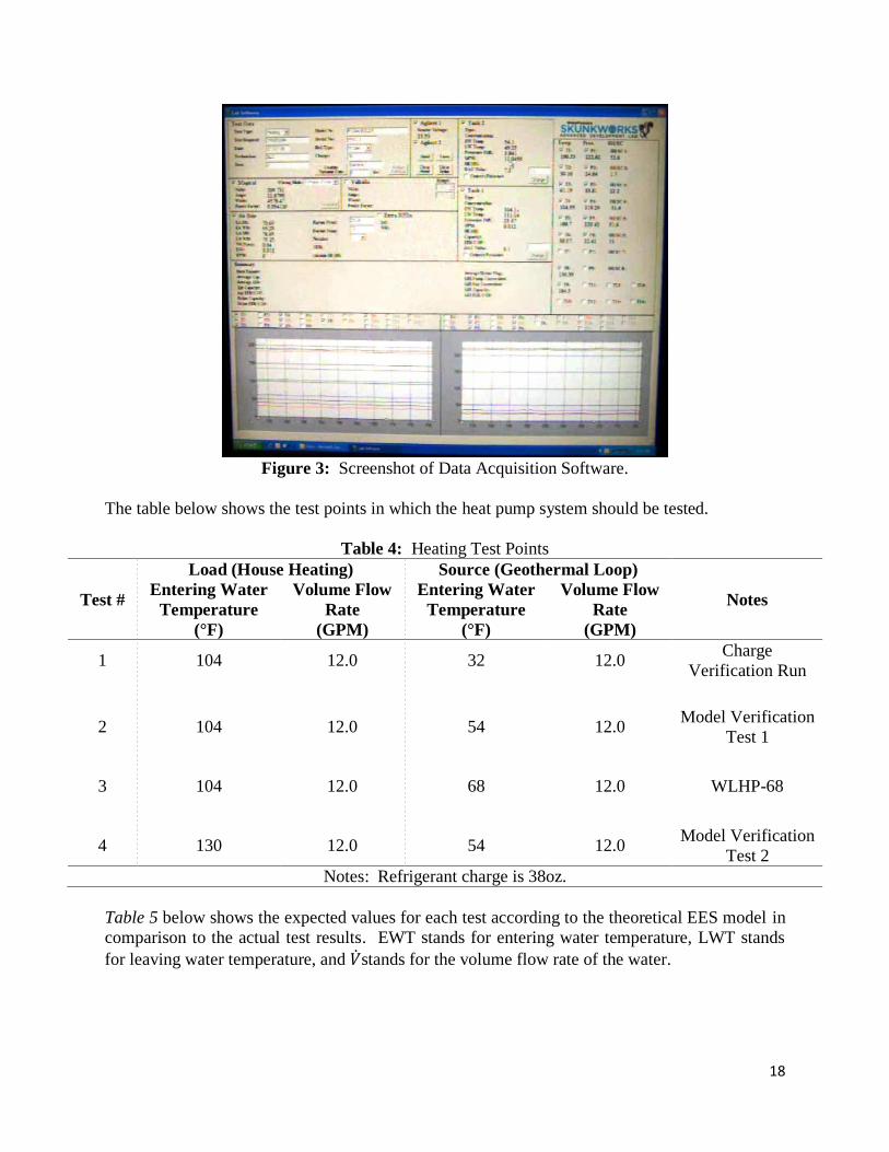
The table below shows the test points in which the heat pump system should be tested.
Table 4: Heating Test Points
Test #
Load (House Heating) Source (Geothermal Loop)
Notes Entering Water
Temperature
(°F)
Volume Flow
Rate
(GPM)
Entering Water
Temperature
(°F)
Volume Flow
Rate
(GPM)
1 104 12.0 32 12.0 Charge
Verification Run
2 104 12.0 54 12.0 Model Verification
Test 1
3 104 12.0 68 12.0 WLHP-68
4 130 12.0 54 12.0 Model Verification
Test 2
Notes: Refrigerant charge is 38oz.
Table 5 below shows the expected values for each test according to the theoretical EES model in
comparison to the actual test results. EWT stands for entering water temperature, LWT stands
for leaving water temperature, and 𝑉 stands for the volume flow rate of the water.

19
Table 5: Expected Results vs. Actual Results
Test
#
Load Source ISO Capacity ISO COP Load LWT (°F)
EWT
(°F)
V_dot
(GPM)
EWT
(°F)
V_dot
(GPM) EES Actual EES Actual EES Actual
1 104 12.0 32 12.0 31500 30150 1.97 1.887 109.1 108.81
2 104 12.0 54 12.0 44326 42671 2.59 2.491 111.3 111.12
3 104 12.0 68 12.0 55233 53898 3.14 3.067 113.2 113.07
4 130 12.0 54 12.0 45730 44262 1.59 1.537 137.9 137.75
Notes: Refrigerant charge is 38oz.
20
Section IV: Evaluation and Recommendations

21
Section IV: Evaluation and Recommendations
Description
The heat pump system will now be evaluated in terms of the given parameters, the EES model
values, and the actual values obtained during the testing of the prototype.
Results Analysis
The differences between the expected results and the actual results can be explained by
assumptions made in the EES modeling. First, the expansion valve is assumed to be an ideal
device. Therefore, any losses occurring in this control volume are neglected and the expansion
valve is treated as a constant enthalpy device.
Second, heat is lost to the environment throughout the entire heat pump cycle. The pipes and
components of the heat pump system cannot be perfectly insulated. Therefore, heat transfer will
occur between the refrigerant and the environment.
The two assumptions described above made the expected results output by the EES model better,
or higher, than the actual results. Overall, the expected results are very close to the actual
results, thus validating the EES model.
The following table compares the requirements set forth by the sponsor company, WaterFurnace
International, to the actual results obtained during testing of the prototype as well as the expected
results output by the EES model.
Table 6: Requirements Comparison and Validation
Parameter Given Value Expected Value
(EES)
Actual Value
(Prototype)
System Capacity ≥ 30,000 Btu/h 44326 Btu/h 42671 Btu/h
Saturation Temperature (Evaporator) 25°F 25°F 25.5°F
Saturation Temperature (Condenser) 120°F 135.2°F 136.1°F
Maximum Pressure < 600 psia 231.8 psia 222.2 psia
Pressure Ratio Not Specified 6.75 9.82
Coefficient of Performance ≥ 2 2.59 2.491
Water Outlet Temperature (Condenser) ≥ 140°F 137.9°F 137.75°F
Recommendations
Note that in Table 6, the condensing saturation temperature is too high when compared to the
given value. Also, the water outlet temperature for the condenser is just under 140°F. The saturation temperature difference is acceptable. However, the water outlet temperature for the
condenser must be above 140°F. Therefore, in order to obtain an exit water temperature of

22
140°F or greater, the volume flow rate on the condenser side must be lowered to less than 9GPM
with the Test 4 conditions. The following table shows the results of the EES model with the
different flow rates.
Table 7: Flow Rate vs. Output Temperature
Condenser
Volume Flow Rate Temperature Output
(GPM) (°F)
12 137.9
11 138.6
10 139.3
9 140.2
8 141.3
The figure below shows a plot of the data from Table 7.
Figure 4: Volume Flow Rate vs. Temperature Output
Other variables that could be changed to provide a higher temperature output would be adding
more plates to the heat exchangers or replacing the plates with higher heat transfer coefficient
plates.
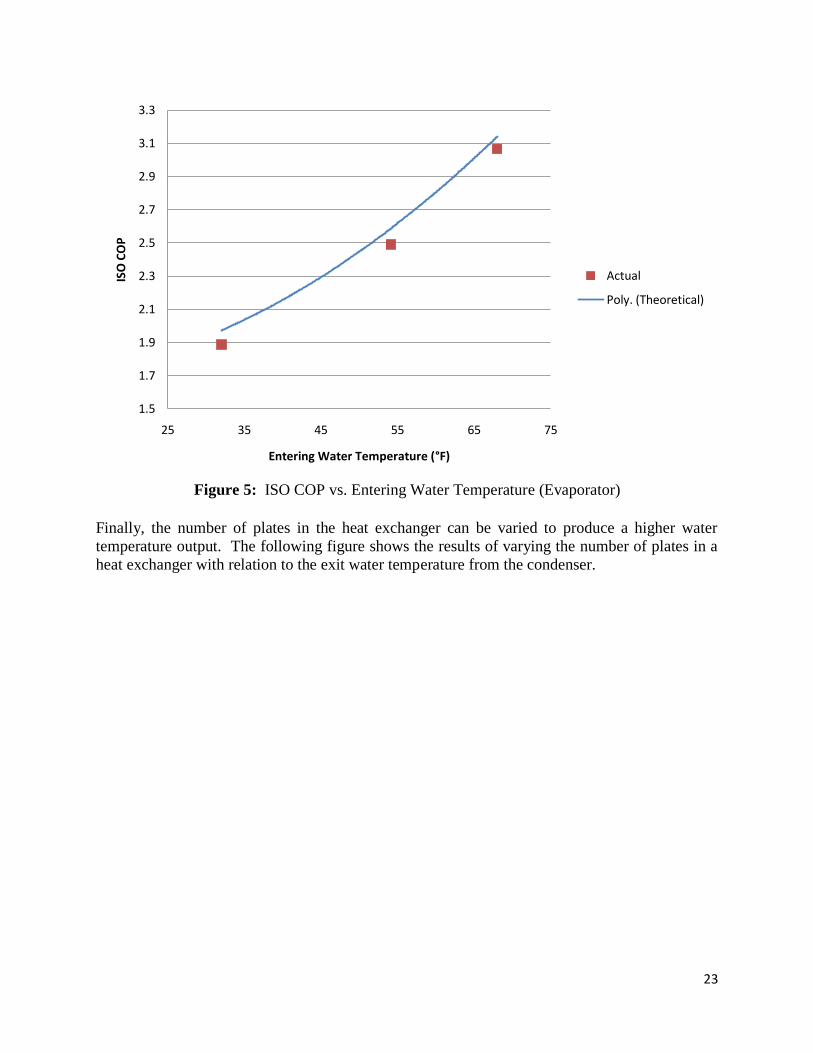
The entering water temperature of the evaporator also changes the ISO COP for the heat pump
system. The following figure shows the trend produced when varying the entering water
temperature for the evaporator with relation to the ISO COP.
137.5
138.0
138.5
139.0
139.5
140.0
140.5
141.0
141.5
78910111213
Vo
lum
e Fl
ow
Rat
e (G
PM
)
Temperature Output (°F)
23
Figure 5: ISO COP vs. Entering Water Temperature (Evaporator)
Finally, the number of plates in the heat exchanger can be varied to produce a higher water
temperature output. The following figure shows the results of varying the number of plates in a
heat exchanger with relation to the exit water temperature from the condenser.
1.5
1.7
1.9
2.1
2.3
2.5
2.7
2.9
3.1
3.3
25 35 45 55 65 75
ISO
CO
P
Entering Water Temperature (°F)
Actual
Poly. (Theoretical)

24
Figure 6: Number of Plates vs. EWT and ISO COP
From Figure 6, as the number of plates in the heat exchangers increases, the exiting water
temperature and ISO COP increase. The critical value for the number of plates required to meet
the revised test point is 18. The current heat exchangers only have 14 plates in them.
Conclusion
In conclusion, the tests resulted in very close values when comparing the EES model values with
the actual test values. The actual experimental results are lower than the expected results due to
minor losses not taken into account by the model.
Moreover, the parameters set by the sponsor company, WaterFurnace International, were all met
with exception of the water outlet temperature for the condenser. However, multiple
recommendations were given which would allow the heat pump system to achieve the specified
outlet water temperature for the condenser. The senior design group recommends lowering the
volume flow rate of the water traveling through the condenser in order to achieve the necessary
exit water temperature. This is the least expensive method of obtaining the required exit water
temperature.
0
0.5
1
1.5
2
2.5
3
138
140
142
144
146
148
150
12 14 16 18 20 22 24
Exit
ing
Wat
er T
emp
erat
ure
(°F
)
Number of Plates
COP
EWT

25
Cost Analysis / Estimation
26
Cost Analysis / Estimation
Objective
This section outlines the process utilized to determine the initial cost and annual cost to install
and run a geothermal R-134a boiler. The cost is based on the project having a heating load of
36,000 Btu/h in Fort Wayne, Indiana. The cost of the R-134a boiler includes the ground loop
along with the anticipated payback time after replacing several different boiler types. The
complete cost of the R-134a boiler is compared to alternative systems which include propane,
fuel oil, natural gas, and electric resistance boiler units.
Procedure
The initial data that needed to be compiled was the current utility rates for each of the alternative
systems. The utility rate costs, listed below in Table 8, were researched on the internet through
reliable official government and energy websites.
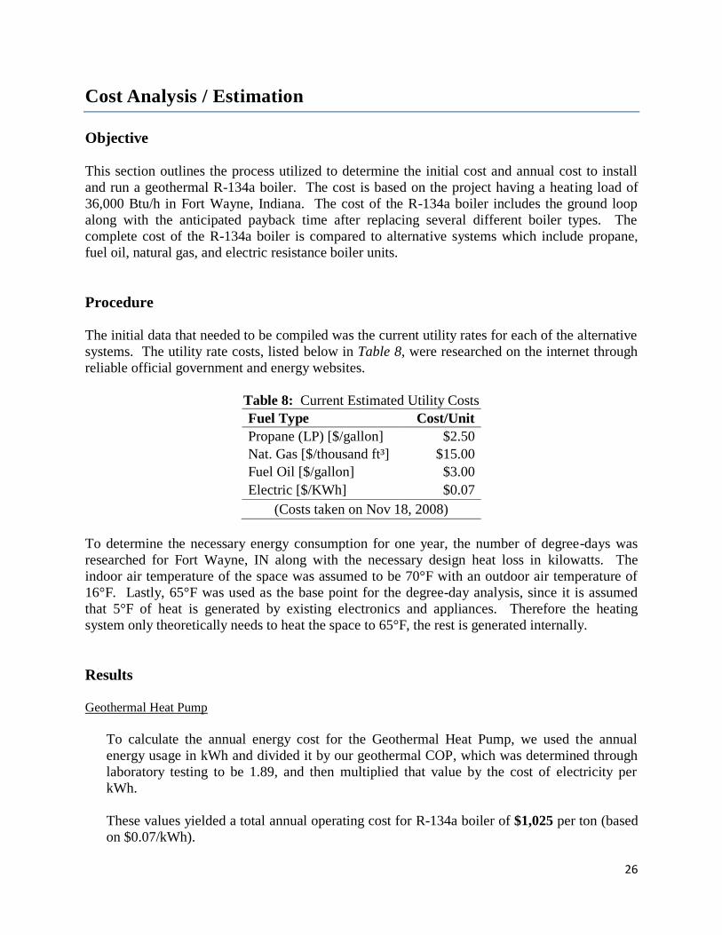
Table 8: Current Estimated Utility Costs
Fuel Type Cost/Unit
Propane (LP) [$/gallon] $2.50
Nat. Gas [$/thousand ft³] $15.00
Fuel Oil [$/gallon] $3.00
Electric [$/KWh] $0.07
(Costs taken on Nov 18, 2008)
To determine the necessary energy consumption for one year, the number of degree-days was
researched for Fort Wayne, IN along with the necessary design heat loss in kilowatts. The
indoor air temperature of the space was assumed to be 70°F with an outdoor air temperature of
16°F. Lastly, 65°F was used as the base point for the degree-day analysis, since it is assumed
that 5°F of heat is generated by existing electronics and appliances. Therefore the heating
system only theoretically needs to heat the space to 65°F, the rest is generated internally.
Results Geothermal Heat Pump
To calculate the annual energy cost for the Geothermal Heat Pump, we used the annual
energy usage in kWh and divided it by our geothermal COP, which was determined through
laboratory testing to be 1.89, and then multiplied that value by the cost of electricity per
kWh.
These values yielded a total annual operating cost for R-134a boiler of $1,025 per ton (based
on $0.07/kWh).
27
The loop is sized for 3 tons, and at a cost of $1,025 per ton this generates a total loop cost of
approximately $3,075. Analyzing the cost of the components required to assemble the heat
pump totaled $2,300, which when marked up 50% for retail sale comes to $3,450. Therefore,
the total cost for the installation of the loop and the unit and the unit itself totals $7,025.
#2 Fuel Oil Boiler
With the assumption that the oil boiler was already installed in the house when the owners
moved in, the only cost would be the annual operating cost which was calculated to be
$2,347 per year for heating (based on an efficiency of 87%).
Natural Gas Boiler
Again, with the assumption that a natural gas boiler was installed previously, the only cost
would be the annual operating cost. The annual operating cost was calculated to be $1,653
per year (based on an efficiency of 84%).
Utilizing the same calculation process for an EnergyStar rated natural gas boiler yielded
cheaper annual operating results due to the higher efficiencies. The annual operating cost
was calculated to be $1,461 per year (based on an efficiency of 95%).
Propane Boiler
With a propane boiler already installed, the calculated annual cost for operation is $3,132 per
year (based on an efficiency of 84%).
Utilizing an EnergyStar rated propane boiler with a higher efficiency lowered the annual cost
to $2,770 (based on an efficiency of 95%).
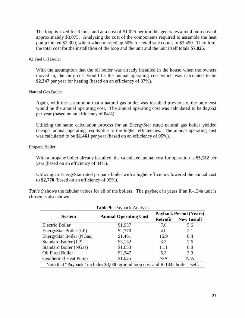
Table 9 shows the tabular values for all of the boilers. The payback in years if an R-134a unit is
chosen is also shown.
Table 9: Payback Analysis
System Annual Operating Cost Payback Period (Years)
Retrofit New Install
Electric Boiler $1,937 7.6 5.6
EnergyStar Boiler (LP) $2,770 4.0 2.1
EnergyStar Boiler (NGas) $1,461 15.9 8.4
Standard Boiler (LP) $3,132 3.3 2.6
Standard Boiler (NGas) $1,653 11.1 8.8
Oil Fired Boiler $2,347 5.3 3.9
Geothermal Heat Pump $1,025 N/A N/A
Note that “Payback” includes $3,000 ground loop cost and R-134a boiler itself.
28
Conclusion
From the above analysis, it was determined to be beneficial to purchase an R-134a boiler unit if
the residence does not have a high efficiency (EnergyStar rated) natural gas boiler already
installed. If the house contains a standard efficiency propane boiler then the payback for
purchasing this R-134a unit will be approximately 3.3 years. In addition, the payback may be
shortened by 30% if a currently available tax credit for geothermal installations were to be
applied. This analysis assumes that the current boiler has no salvage value in a retrofit situation.
The calculation for the payback analysis included the ground loop and the cost of the heat pump
itself. The calculation for new installation took into account average purchase prices for
similarly sized systems to the geothermal heat pump.

29
Conclusion

30
Conclusion
In conclusion, the parameters of the heat pump system that were given have all been met when
using the initial test point. However, when using the revised test point, the coefficient of
performance is slightly under the specified value of 2. Also, the exit water temperature from the
condenser is just under the specified value of 140°F. Therefore, the original design did not allow
the heat pump system to be a direct replacement for boiler systems without any needed
modification to the radiator water delivery system. However, the heat pump system has been
designed to deliver 3 tons of heat to the radiator water delivery system as specified per the initial
test point. Recommendations have been given to improve the exit water temperature to meet the
given requirements. Lastly, the EES model accurately models the heat pump system and its
behavior.

Appendix A: Step by Step Pictorial of Heat Pump Build
Figure 7: Placing the compressor on one side of the frame.
Figure 8: Placing the condenser, evaporator, and expansion valve on the opposite end.
32
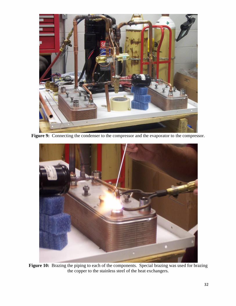
Figure 9: Connecting the condenser to the compressor and the evaporator to the compressor.
Figure 10: Brazing the piping to each of the components. Special brazing was used for brazing
the copper to the stainless steel of the heat exchangers.

33
Figure 11: Attaching the piping to condenser for exit and re-entry water.
Figure 12: Brazing the condenser piping.
34
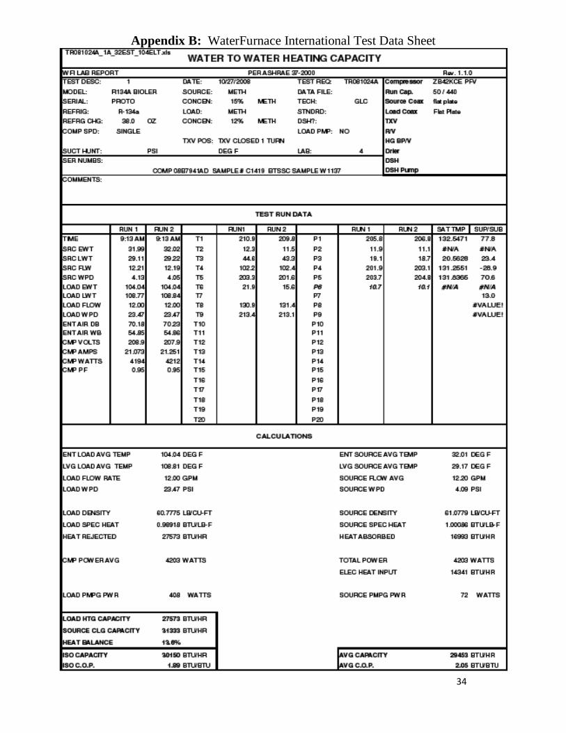
Appendix B: WaterFurnace International Test Data Sheet
35
Appendix C: EES Example Code
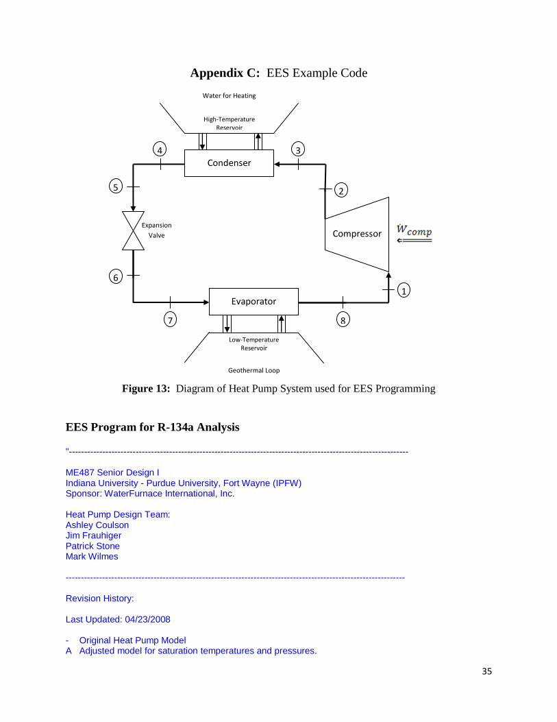
Figure 13: Diagram of Heat Pump System used for EES Programming
EES Program for R-134a Analysis "---------------------------------------------------------------------------------------------------------------- ME487 Senior Design I Indiana University - Purdue University, Fort Wayne (IPFW) Sponsor: WaterFurnace International, Inc. Heat Pump Design Team: Ashley Coulson Jim Frauhiger Patrick Stone Mark Wilmes ---------------------------------------------------------------------------------------------------------------- Revision History: Last Updated: 04/23/2008 - Original Heat Pump Model A Adjusted model for saturation temperatures and pressures.
Low-Temperature Reservoir
Geothermal Loop
Evaporator
Compressor
1
7
Expansion
Valve
3
5
High-Temperature Reservoir
Condenser
Water for Heating
2
4
6
8

36
B Added pressure drop due to friction and elevation in connecting pipes. C Tried using Log Mean Temperature Difference (LMTD) heat exchanger analysis. D Added NTU heat exchanger analysis. E Added Parametric Table with varying saturation temperatures. F Adjusted thermal conductivity for NTU analysis to be an average of inlet and outlet values. Added friction factor calculation to EES (used to be done in Matlab). G Adjusted NTU Method (Nusselt number now based on flow type, velocity dependent on number of channels) H Changed where the saturation pressure is calculated (from State 8 to State 6) Adjusted c_p calculations and C calculations in NTU method. Inserted information for new compressor (higher efficiency). I Adjusted model for new ISO Capacity and ISO COP (uses pumping power for load and source). J Finalized for WaterFurnace International. ---------------------------------------------------------------------------------------------------------------- Design Information: 1. Heat Pump design using following given specifications. Must deliver water at T >= 140 degrees Farenheit (T >= 60 degrees Celcius). Pressure must not exceed 600psi for safety reasons. The Coefficient of Performance must be greater than or equal to 2. The unit must have a system capacity of at least 30,000 Btu/h. 2. The following design assumptions will be made. The enthalpy difference from the inlet and outlet expansion valve is zero (h_6=h_5). The compressor is insulated (q_comp=0). ---------------------------------------------------------------------------------------------------------------- Pressure Drop in Connecting Pipe: P_B=P_A-rho*g*(delta_z+f*(L/D)*(V^2/(2*g))) A is beginning of pipe, B is end of pipe rho is refrigerant density g is acceleration of gravity delta_z is the difference in height of the two ends of the pipe f is the Darcy Friction Factor (solved for using the Regula Falsi Method in Matlab with the Haaland Equation as the initial estimate) L is the length of the pipe D is the diameter of the pipe V is the average fluid velocity ----------------------------------------------------------------------------------------------------------------" "--------------------------------------------------------------------------------------------------------------- Component and Piping Information ---------------------------------------------------------------------------------------------------------------" "!Test Point Data - INPUTS" T_water_cond_i=104.2[F] {Inlet Water Temperature, Condenser} V_dot_water_cond=12.00[GPM] {Water Volume Flow Rate} T_water_evap_i=54.13[F] {Inlet Water Temperature, Evaporator} V_dot_water_evap=12.07[GPM] {Water Volume Flow Rate} Power_comp=4546[W] {Power of Compressor} eta_comp=0.536 {Isentropic Efficiency, Compressor}
37
T_sat_evap=25.0[F] {Saturation Temperature for Evaporator} T_sat_cond=136.1[F] {Saturation Temperature for Condenser} superheat=13.5[F] {Superheat, Condenser} subcool=--29.2[F] {Subcool, Evaporator} “!End INPUTS” "--------------------------------------------------------------------------------------------------------------- Component and Piping Information ---------------------------------------------------------------------------------------------------------------" "!Compressor Information" " Copeland ZB42KCE-PFV " W_dot_comp=Power_comp*Power_conv2 {Work Required by Compressor} m_dot_comp=488[lb_m/h] {Mass Flow Rate, Compressor} "!Conversion Factors" V_dot_conv=(7.481/60)[gal-h/ft^3-min] {Conversion to/from GPM} V_dot_conv2=8.0208[ft^3-min/gal-h] {Conversion to/from ft^3/h} Power_conv=1.44997[W/GPM-psia] {Conversion to/from Watts} Power_conv2=3.412[Btu/h-W] {Conversion to/from Btu/h} "!Condenser Information" " FlatPlate C3A Cond : 120[F] Capacity : 36000[Btu/h] Pressure Drop Refrigerant Side: 0.4[psia] Area : 10.7[ft^2] Channel Width : 4.9[in] = 0.408[ft] Channel Height : 0.007226[ft] Refrigerant Number of Channels : 14 Water Number of Channels : 15 Refrigerant Fouling Factor : 0.0002[m^2-K/W] / 0.176118 = 0.001136[h-ft^2-F/Btu] Water Fouling Factor : 0.0001[h-ft^2-F/Btu] " "Condenser Dimensions" width_cond=0.408[ft] {Channel Width, Condenser} height_cond=0.007226[ft] {Channel Height, Condenser} length_cond=(9.96/12)[ft] {Channel Length, Condenser} A_c_cond=width_cond*height_cond {Channel Cross Sectional Area, Condenser} P_cond=2*(width_cond+height_cond) {Channel Perimeter, Condenser} D_h_cond=(4*A_c_cond)/P_cond {Hydraulic Diameter, Condenser} n_ref_cond=14 {Number of Refrigerant Channels, Condenser} n_water_cond=n_ref_cond+1 {Number of Water Channels, Condenser} P_drop_water_cond=23.47[psia] {Water Pressure Drop, Condenser} x_1=T_water_evap_i "Refrigerant Fluid Properties, Condenser" rho_ref_cond_i=density(R134a, T=T_3, P=P_3) {Inlet Refrigerant Density, Condenser} rho_ref_cond_o=density(R134a, T=T_4, P=P_4) {Outlet Refrigerant Density, Condenser} rho_ref_cond=(rho_ref_cond_i+rho_ref_cond_o)/2 {Average Refrigerant Density, Condenser} mu_ref_cond_i=viscosity(R134a, T=T_3, P=P_3) {Inlet Refrigerant Viscosity, Condenser} mu_ref_cond_o=viscosity(R134a, T=T_4, P=P_4) {Outlet Refrigerant Viscosity, Condenser} mu_ref_cond=(mu_ref_cond_i+mu_ref_cond_o)/2 {Average Refrigerant Viscosity, Condenser}

38
k_ref_cond_i=conductivity(R134a, T=T_3, P=P_3) {Refrigerant Thermal Conductivity In, Condenser} k_ref_cond_o=conductivity(R134a, T=T_4, P=P_4) {Refrigerant Thermal Conductivity Out, Condenser} k_ref_cond=(k_ref_cond_i+k_ref_cond_o)/2 {Average of Refrigerant Thermal Conductivity, Condenser} c_p_ref_cond=1e20[Btu/lb_m-F] {Refrigerant Specific Heat (Infinite)} V_bar_ref_cond=(m_dot_comp/(rho_ref_cond*A_c_cond))/n_ref_cond {Average Refrigerant Velocity, Condenser} Re_ref_cond=(rho_ref_cond*V_bar_ref_cond*D_h_cond)/mu_ref_cond {Refrigerant Reynolds Number, Condenser} Pr_ref_cond=(c_p_ref_cond*mu_ref_cond)/k_ref_cond {Refrigerant Prandtl Number, Condenser} Nus_ref_cond=0.374*Re_ref_cond^0.668*Pr_ref_cond^(1/3) {Refrigerant Nusselt Number, Condenser, Turbulent Flow} "Water Fluid Properties, Condenser" rho_water_cond=density(water, T=T_water_cond_i, X=0) {Water Density, Condenser} mu_water_cond=viscosity(water, T=T_water_cond_i, X=0) {Water Viscosity, Condenser} k_water_cond=conductivity(water, T=T_water_cond_i, X=0) {Water Thermal Conductivity, Condenser} c_p_water_cond=CP(water, T=T_water_cond_i, X=0) {Water Specific Heat, Condenser} V_bar_water_cond=(m_dot_water_cond/(rho_water_cond*A_c_cond))/n_water_cond {Average Water Velocity, Condenser} Re_water_cond=(rho_water_cond*V_bar_water_cond*D_h_cond)/mu_water_cond {Water Reynolds Number, Condenser} Pr_water_cond=(c_p_water_cond*mu_water_cond)/k_water_cond {Water Prandtl Number, Condenser} Nus_water_cond=1.86*((D_h_cond*Re_water_cond*Pr_water_cond)/length_cond)^(1/3) {Water Nusselt Number, Condenser, Laminar Flow} "Heat Transfer Coefficients, Condenser" h_ref_cond_theory=(Nus_ref_cond*k_ref_cond)/D_h_cond {Refrigerant Heat Transfer Coefficient, Condenser} h_water_cond_theory=(Nus_water_cond*k_water_cond)/D_h_cond {Water Heat Transfer Coefficient, Condenser} h_ref_cond=403[Btu/h-ft^2-F] {Refrigerant Heat Transfer Coefficient, Condenser} h_water_cond=64[Btu/h-ft^2-F] {Water Heat Transfer Coefficient, Condenser} "Thermal Resistances" R_ref_cond=1/h_ref_cond {Refrigerant Resistance, Condenser} R_water_cond=1/h_water_cond {Water Resistance, Condenser} R_ff_ref_cond=0.001136[h-ft^2-F/Btu] {Refrigerant Fouling Factor, Condenser} R_ff_water_cond=0.0001[h-ft^2-F/Btu] {Water Fouling Factor, Condenser} R_sum_cond=R_ref_cond+R_water_cond+R_ff_ref_cond+R_ff_water_cond {Resistance Sum, Condenser} "Set up for NTU Method" U_cond=0.0462*x_1^2-3.7001*x_1+96.129 {Overall Heat Transfer Coefficient, Condenser} A_cond=10.7[ft^2] {Nominal Surface Area, Condenser}

39
P_drop_cond=0.4[psia] {Condenser Pressure Drop} m_dot_water_cond=(V_dot_water_cond/V_dot_conv)*rho_water_cond {Water Mass Flow Rate, Condenser} C_w_cond=m_dot_water_cond*c_p_water_cond {Water Coefficient} C_r_cond=0 {Specific Heat Capacity Ratio} "Solve using NTU Method" NTU_cond=(U_cond*A_cond)/C_w_cond {NTU, Condenser} epsilon_cond=1-exp(-NTU_cond) {Effectiveness, Condenser} Q_dot_cond_NTU=epsilon_cond*C_w_cond*(T_3-T_water_cond_i) {NTU Capacity, Condenser} Q_dot_cond_rejected=V_dot_water_cond*V_dot_conv2*rho_water_cond*c_p_water_cond*(T_water_cond_o-T_water_cond_i) {Water Heat Transfer, Condenser} Power_load_pumping=V_dot_water_cond*P_drop_water_cond*Power_conv {Load Pumping Power} T_water_cond_o=T_water_cond_i+epsilon_cond*(T_3-T_water_cond_i) {Temperature of Water Output, Condenser} "!Evaporator Information" " FlatPlate CH3A Evap : 25[F] Capacity : 36000[Btu/h] Pressure Drop Refrigerant Side: 2.1[psia] Area : 10.7[ft^2] Channel Width : 4.9[in] = 0.408[ft] Channel Height : 0.007226[ft] Refrigerant Number of Channels : 14 Water Number of Channels : 15 Refrigerant Fouling Factor : 0.0002[m^2-K/W] / 0.176118 = 0.001136[h-ft^2-F/Btu] Water Fouling Factor : 0.0001[h-ft^2-F/Btu] " "Evaporator Dimensions" width_evap=0.408[ft] {Channel Width, Evaporator} height_evap=0.007226[ft] {Channel Height, Evaporator} length_evap=(9.96/12)[ft] {Channel Length, Evaporator} A_c_evap=width_evap*height_evap {Channel Cross Sectional Area, Evaporator} P_evap=2*(width_evap+height_evap) {Channel Perimeter, Evaporator} D_h_evap=(4*A_c_evap)/P_evap {Hydraulic Diameter, Evaporator} n_ref_evap=n_ref_cond {Number of Refrigerant Channels, Evaporator} n_water_evap=n_ref_evap+1 {Number of Water Channels, Evaporator} P_drop_water_evap=3.82[psia] {Water Pressure Drop, Evaporator} "Refrigerant Fluid Properties, Evaporator" rho_ref_evap_i=density(R134a, T=T_7, H=h_7) {Inlet Refrigerant Density, Evaporator} rho_ref_evap_o=density(R134a, T=T_8, P=P_8) {Outlet Refrigerant Density, Evaporator} rho_ref_evap=(rho_ref_evap_i+rho_ref_evap_o)/2 {Average Refrigerant Density, Evaporator} mu_ref_evap_i=viscosity(R134a, T=T_7, X=0) {Inlet Refrigerant Viscosity, Evaporator} mu_ref_evap_o=viscosity(R134a, T=T_8, X=1) {Outlet Refrigerant Viscosity, Evaporator} mu_ref_evap=(mu_ref_evap_i+mu_ref_evap_o)/2 {Average Refrigerant Viscosity, Evaporator} k_ref_evap_i=conductivity(R134a, T=T_7, X=0) {Refrigerant Thermal Conductivity In, Evaporator} k_ref_evap_o=conductivity(R134a, T=T_8, X=1) {Refrigerant Thermal Conductivity Out, Evaporator}

40
k_ref_evap=(k_ref_evap_i+k_ref_evap_o)/2 {Average of Refrigerant Thermal Conductivity, Evaporator} c_p_ref_evap=1e20[Btu/lb_m-F] {Refrigerant Specific Heat (Infinite)} V_bar_ref_evap=(m_dot_comp/(rho_ref_evap*A_c_evap))/n_ref_evap {Average Refrigerant Velocity, Evaporator} Re_ref_evap=(rho_ref_evap*V_bar_ref_evap*D_h_evap)/mu_ref_evap {Refrigerant Reynolds Number, Evaporator} Pr_ref_evap=(c_p_ref_evap*mu_ref_evap)/k_ref_evap {Refrigerant Prandtl Number, Evaporator} Nus_ref_evap=0.374*Re_ref_evap^0.668*Pr_ref_evap^(1/3) {Refrigerant Nusselt Number, Evaporator, Turbulent Flow} "Water Fluid Properties, Evaporator" rho_water_evap=density(water, T=T_water_evap_i, X=0) {Water Density, Evaporator} mu_water_evap=viscosity(water, T=T_water_evap_i, X=0) {Water Viscosity, Evaporator} k_water_evap=conductivity(water, T=T_water_evap_i, X=0) {Water Thermal Conductivity, Evaporator} c_p_water_evap=CP(water, T=T_water_evap_i, X=0) {Water Specific Heat, Evaporator} V_bar_water_evap=(m_dot_water_evap/(rho_water_evap*A_c_evap))/n_water_evap {Average Water Velocity, Evaporator} Re_water_evap=(rho_water_evap*V_bar_water_evap*D_h_evap)/mu_water_evap {Water Reynolds Number, Evaporator} Pr_water_evap=(c_p_water_evap*mu_water_evap)/k_water_evap {Water Prandtl Number, Evaporator} Nus_water_evap=1.86*((D_h_evap*Re_water_evap*Pr_water_evap)/length_evap)^(1/3) {Water Nusselt Number, Evaporator, Laminar Flow} "Heat Transfer Coefficients, Evaporator" h_ref_evap_theory=(Nus_ref_evap*k_ref_evap)/D_h_evap {Refrigerant Heat Transfer Coefficient, Evaporator} h_water_evap_theory=(Nus_water_evap*k_water_evap)/D_h_evap {Water Heat Transfer Coefficient, Evaporator} h_ref_evap=162[Btu/h-ft^2-F] {Refrgierant heat Transfer Coefficient, Evaporator} h_water_evap=81[Btu/h-ft^2-F] {Water Heat Transfer Coefficient, Evaporator} "Thermal Resistances" R_ref_evap=1/h_ref_evap {Refrigerant Resistance, Evaporator} R_water_evap=1/h_water_evap {Water Resistance, Evaporator} R_ff_ref_evap=0.001136[h-ft^2-F/Btu] {Refrigerant Fouling Factor, Evaporator} R_ff_water_evap=0.0001[h-ft^2-F/Btu] {Water Fouling Factor, Evaporator} R_sum_evap=R_ref_evap+R_water_evap+R_ff_ref_evap+R_ff_water_evap {Resistance Sum, Evaporator} "Set up for NTU Method" U_evap=0.2818*x_1^2-30.857*x_1+945.92 {Overall Heat Transfer Coefficient, Condenser} A_evap=10.7[ft^2] {Nominal Surface Area, Evaporator} P_drop_evap=2.1[psia] {Evaporator Pressure Drop} m_dot_water_evap=(V_dot_water_evap/V_dot_conv)*rho_water_evap {Water Mass Flow Rate, Evaporator} C_w_evap=m_dot_water_evap*c_p_water_evap {Water Coefficient} C_r_evap=0 {Specific Heat Capacity Ratio}

41
"Solve using NTU Method" NTU_evap=(U_evap*A_evap)/C_w_evap {NTU, Evaporator} epsilon_evap=1-exp(-NTU_evap) {Effectiveness, Evaporator} Q_dot_evap_NTU=epsilon_evap*C_w_evap*(T_water_evap_i-T_7) {NTU Capacity, Evaporator} Q_dot_evap_absorbed=V_dot_water_evap*V_dot_conv2*rho_water_evap*c_p_water_evap*(T_water_evap_i-T_water_evap_o) {Water Heat Transfer, Evaporator} Power_source_pumping=V_dot_water_evap*P_drop_water_evap*Power_conv {Source Pumping Power} T_water_evap_o=T_water_evap_i+epsilon_evap*(T_7-T_water_evap_i) {Temperature of Water Output, Evaporator} "!ISO Calculations" Capacity_heating_ISO=(Q_dot_cond_rejected+Q_dot_evap_absorbed+Power_load_pumping+W_dot_comp)/2 {ISO Heating Capacity} COP_ISO=Capacity_heating_ISO/((Power_comp+Power_load_pumping+Power_source_pumping)*Power_conv2) {ISO Coefficient of Performance} "!Pipe Information" g=(4.17312*10^8)[ft/h^2] {Acceleration of Gravity} e=0.000005[ft] {Roughness, Drawn Tubing} D=((5/8)/12)[ft] {Pipe Diameter} RR=e/D {Relative Roughness} A=(PI/4)*D^2 {Pipe Area} c3=(1.66543*10^(-11))[psia/(lb_m/ft-h^2)] {psia Conversion Factor} "--------------------------------------------------------------------------------------------------------------- System Solution by Control Volume ---------------------------------------------------------------------------------------------------------------" "---------------------------------------------" {State 1 to State 2} {Control Volume : Compressor} "!State 1 : Compressor Inlet" {Refrigerant Entering Compressor} s_1=s_8 {Specific Entropy} T_1=temperature(R134a, P=P_1, S=s_1) {Temperature} h_1=enthalpy(R134a, P=P_1, S=s_1) {Specific Entropy} "!State2s : Compressor Outlet, Ideal" {Refrigerant Exiting Compressor (Ideal: Isentropic)} P_2=P_sat(R134a, T=T_sat_cond) {Pressure, Found using Saturation Temperature Given by WaterFurnace} s_2s=s_1 {Specific Entropy} h_2s=enthalpy(R134a, P=P_2, S=s_2s) {Specific Enthalpy} T_2s=temperature(R134a, P=P_2, H=h_2s) {Temperature} "!State 2a : Compressor Outlet, Actual" {Refrigerant Exiting Compressor (Actual: Not Isentropic)} h_2a=(h_2s-h_1)/eta_comp+h_1 {Specific Enthalpy, Solved from Compressor Efficiency} T_2a=temperature(R134a, P=P_2, H=h_2a) {Temperature} s_2a=entropy(R134a, P=P_2, H=h_2a) {Specific Entropy}

42
"---------------------------------------------" "---------------------------------------------" {State 2 to State 3} {Control Volume : Connecting Pipe} "!Refrigerant Properties" rho_2=density(R134a, T=T_2a, P=P_2) {Density} mu_2=viscosity(R134a, T=T_2a, P=P_2) {Viscosity} V_bar_2=m_dot_comp/(rho_2*A) {Fluid Velocity} Re_2=(rho_2*V_bar_2*D)/mu_2 {Reynolds Number} 1/sqrt(f_2)=-2*log10(RR/3.7+2.51/(Re_2*sqrt(f_2))) {Friction Factor, Turbulent Flow} "!Pipe Characteristics" z_2=0[ft] {Height of State 2 Pipe} z_3=(-3.5/12)[ft] {Height of State 3 Pipe} DELTA_z_2to3=z_3-z_2 {Difference in Height} L_2to3=(6/12)[ft] {Length of Pipe} "!Pressure Drop Calculation" c1_2=rho_2*g*DELTA_z_2to3 {Height Variable} c2_2=rho_2*g*f_2*(L_2to3/D)*(V_bar_2^2)/(2*g) {Velocity Variable} P_3=P_2-(c1_2+c2_2)*c3 {Pressure Drop} "---------------------------------------------" "---------------------------------------------" {State 3 to State 4} {Control Volume : Condenser} "!State 3 : Condenser Inlet" {Refrigerant Entering Condenser} s_3=s_2a {Specfic Entropy} T_3=temperature(R134a, P=P_3, S=s_3) {Temperature} "h_3=enthalpy(R134a, P=P_3, S=s_3) {Specific Enthalpy}" "!State 4 : Condenser Outlet" {Refrigerant Exiting Condenser} T_4=T_sat_cond+subcool {Temperature, Plus Negative Subcool, Given by WaterFurnace} P_4=P_3-P_drop_cond {Pressure} h_4=enthalpy(R134a, T=T_4, P=P_4) {Specific Enthalpy} s_4=entropy(R134a, T=T_4, P=P_4) {Specific Entropy} "---------------------------------------------" "---------------------------------------------" {State 4 to State 5} {Control Volume : Connecting Pipe} "!Refrigerant Properties" rho_4=density(R134a, T=T_4, P=P_4) {Density} mu_4=viscosity(R134a, T=T_4, P=P_4) {Viscosity} V_bar_4=m_dot_comp/(rho_4*A) {Fluid Velocity} Re_4=(rho_4*V_bar_4*D)/mu_4 {Reynolds Number} 1/sqrt(f_4)=-2*log10(RR/3.7+2.51/(Re_4*sqrt(f_4))) {Friction Factor, Turbulent Flow} "!Pipe Characteristics" z_4=0[ft] {Height of State 4 Pipe} z_5=(5/12)[ft] {Height of State 5 Pipe} DELTA_z_4to5=z_5-z_4 {Difference in Height} L_4to5=(6.5/12)[ft] {Length of Pipe}
43
"!Pressure Drop Calculation" c1_4=rho_4*g*DELTA_z_4to5 {Height Variable} c2_4=rho_4*g*f_4*(L_4to5/D)*(V_bar_4^2)/(2*g) {Velocity Variable} P_5=P_4-(c1_4+c2_4)*c3 {Pressure Drop} "---------------------------------------------" "---------------------------------------------" {State 5 to State 6} {Control Volume : Expansion Valve} "!State 5 : Expansion Valve Inlet" {Refrigerant Entering Expansion Valve} s_5=s_4 {Specific Entropy} T_5=temperature(R134a, P=P_5, S=s_5) {Temperature} h_5=enthalpy(R134a, P=P_5, S=s_5) {Specific Enthalpy} "!State 6 : Expansion Valve Outlet" {Refrigerant Exiting Expansion Valve} T_6=T_sat_evap {Temperature} P_6=P_sat(R134a, T=T_6) {Pressure} h_6=h_5 {Specific Enthalpy} s_6=0.1033 "s_6=entropy(R134a, T=T_6, H=h_6) {Specific Entropy}" "---------------------------------------------" "---------------------------------------------" {State 6 to State 7} {Control Volume : Connecting Pipe} "!Refrigerant Properties" rho_6=density(R134a, T=T_6, X=0) {Density} mu_6=viscosity(R134a, T=T_6, X=0) {Viscosity} V_bar_6=m_dot_comp/(rho_6*A) {Fluid Velocity} Re_6=(rho_6*V_bar_6*D)/mu_6 {Reynolds Number} 1/sqrt(f_6)=-2*log10(RR/3.7+2.51/(Re_6*sqrt(f_6))) {Friction Factor, Turbulent Flow} "!Pipe Characteristics" z_6=0[ft] {Height of State 6 Pipe} z_7=(5/12)[ft] {Height of State 7 Pipe} DELTA_z_6to7=z_7-z_6 {Difference in Height} L_6to7=(6.5/12)[ft] {Length of Pipe} "!Pressure Drop Calculation" c1_6=rho_6*g*DELTA_z_6to7 {Height Variable} c2_6=rho_6*g*f_6*(L_6to7/D)*(V_bar_6^2)/(2*g) {Velocity Variable} P_7=P_6-(c1_6+c2_6)*c3 {Pressure Drop} "---------------------------------------------" "---------------------------------------------" {State 7 to State 8} {Control Volume : Evaporator} "!State 7 : Evaporator Inlet" {Refrigerant Entering Evaporator} s_7=s_6 {Specific Entropy} T_7=temperature(R134a, P=P_7, S=s_7) {Temperature} "h_7=enthalpy(R134a, P=P_7, S=s_7) {Specific Enthalpy}" "!State 8 : Evaporator Outlet" {Refrigerant Exiting Evaporator} T_8=T_sat_evap+superheat {Temperature, with Superheat, Given by WaterFurnace}
44
P_8=P_7-P_drop_evap {Pressure, Found using Saturation Temperature Given by WaterFurnace} h_8=enthalpy(R134a, T=T_8, P=P_8) {Specific Enthalpy} s_8=entropy(R134a, T=T_8, P=P_8) {Specific Entropy} "---------------------------------------------" "---------------------------------------------" {State 8 to State 1} {Control Volume : Connecting Pipe} "!Refrigerant Properties" rho_8=density(R134a, T=T_8, P=P_8) {Density} mu_8=viscosity(R134a, T=T_8, P=P_8) {Viscosity} V_bar_8=m_dot_comp/(rho_8*A) {Fluid Velocity} Re_8=(rho_8*V_bar_8*D)/mu_8 {Reynolds Number} 1/sqrt(f_8)=-2*log10(RR/3.7+2.51/(Re_8*sqrt(f_8))) {Friction Factor, Turbulent Flow} "!Pipe Characteristics" z_8=0[ft] {Height of State 8 Pipe} z_1=(-2.5/12)[ft] {Height of State 1 Pipe} DELTA_z_8to1=z_1-z_8 {Difference in Height} L_8to1=(10/12)[ft] {Length of Pipe} "!Pressure Drop Calculation" c1_8=rho_8*g*DELTA_z_8to1 {Height Variable} c2_8=rho_8*g*f_8*(L_8to1/D)*(V_bar_8^2)/(2*g) {Velocity Variable} P_1=P_8-(c1_8+c2_8)*c3 {Pressure Drop} "---------------------------------------------" "---------------------------------------------" {Other Calculations} {Pressure Ratio, Heat Transfer, COP} "!Pressure Ratio" {System Pressure Ratio} PR=P_2/P_1 {Pressure Ratio} "!Condenser Heat Transfer" {Condenser Heat Transfer} Q_dot_cond_NTU=m_dot_comp*(h_3-h_4) {Heat Transferred through Condenser} "!Evaporator Heat Transfer" {Evaporator Heat Transfer} Q_dot_evap_NTU=m_dot_comp*(h_8-h_7) {Heat Transferred through Evaporator} "!System Capacity" Capacity_system=(Q_dot_cond_NTU+Q_dot_evap_NTU+W_dot_comp)/2 "!Coefficient of Performance" {Coefficient of Performance} COP_H=Capacity_system/W_dot_comp {Coefficient of Performance, Heating} "---------------------------------------------"
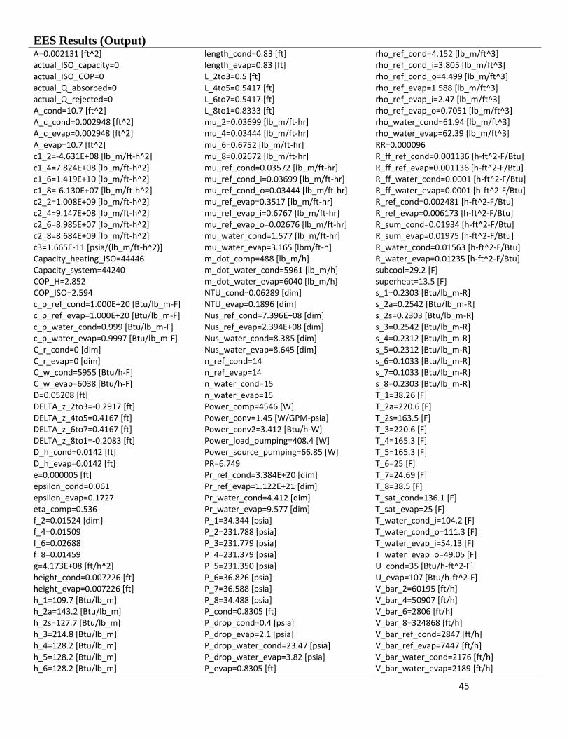
45
EES Results (Output) A=0.002131 [ft^2] length_cond=0.83 [ft] rho_ref_cond=4.152 [lb_m/ft^3] actual_ISO_capacity=0 length_evap=0.83 [ft] rho_ref_cond_i=3.805 [lb_m/ft^3] actual_ISO_COP=0 L_2to3=0.5 [ft] rho_ref_cond_o=4.499 [lb_m/ft^3] actual_Q_absorbed=0 L_4to5=0.5417 [ft] rho_ref_evap=1.588 [lb_m/ft^3] actual_Q_rejected=0 L_6to7=0.5417 [ft] rho_ref_evap_i=2.47 [lb_m/ft^3] A_cond=10.7 [ft^2] L_8to1=0.8333 [ft] rho_ref_evap_o=0.7051 [lb_m/ft^3] A_c_cond=0.002948 [ft^2] mu_2=0.03699 [lb_m/ft-hr] rho_water_cond=61.94 [lb_m/ft^3] A_c_evap=0.002948 [ft^2] mu_4=0.03444 [lb_m/ft-hr] rho_water_evap=62.39 [lb_m/ft^3] A_evap=10.7 [ft^2] mu_6=0.6752 [lb_m/ft-hr] RR=0.000096 c1_2=-4.631E+08 [lb_m/ft-h^2] mu_8=0.02672 [lb_m/ft-hr] R_ff_ref_cond=0.001136 [h-ft^2-F/Btu] c1_4=7.824E+08 [lb_m/ft-h^2] mu_ref_cond=0.03572 [lb_m/ft-hr] R_ff_ref_evap=0.001136 [h-ft^2-F/Btu] c1_6=1.419E+10 [lb_m/ft-h^2] mu_ref_cond_i=0.03699 [lb_m/ft-hr] R_ff_water_cond=0.0001 [h-ft^2-F/Btu] c1_8=-6.130E+07 [lb_m/ft-h^2] mu_ref_cond_o=0.03444 [lb_m/ft-hr] R_ff_water_evap=0.0001 [h-ft^2-F/Btu] c2_2=1.008E+09 [lb_m/ft-h^2] mu_ref_evap=0.3517 [lb_m/ft-hr] R_ref_cond=0.002481 [h-ft^2-F/Btu] c2_4=9.147E+08 [lb_m/ft-h^2] mu_ref_evap_i=0.6767 [lb_m/ft-hr] R_ref_evap=0.006173 [h-ft^2-F/Btu] c2_6=8.985E+07 [lb_m/ft-h^2] mu_ref_evap_o=0.02676 [lb_m/ft-hr] R_sum_cond=0.01934 [h-ft^2-F/Btu] c2_8=8.684E+09 [lb_m/ft-h^2] mu_water_cond=1.577 [lb_m/ft-hr] R_sum_evap=0.01975 [h-ft^2-F/Btu] c3=1.665E-11 [psia/(lb_m/ft-h^2)] mu_water_evap=3.165 [lbm/ft-h] R_water_cond=0.01563 [h-ft^2-F/Btu] Capacity_heating_ISO=44446 m_dot_comp=488 [lb_m/h] R_water_evap=0.01235 [h-ft^2-F/Btu] Capacity_system=44240 m_dot_water_cond=5961 [lb_m/h] subcool=29.2 [F] COP_H=2.852 m_dot_water_evap=6040 [lb_m/h] superheat=13.5 [F] COP_ISO=2.594 NTU_cond=0.06289 [dim] s_1=0.2303 [Btu/lb_m-R] c_p_ref_cond=1.000E+20 [Btu/lb_m-F] NTU_evap=0.1896 [dim] s_2a=0.2542 [Btu/lb_m-R] c_p_ref_evap=1.000E+20 [Btu/lb_m-F] Nus_ref_cond=7.396E+08 [dim] s_2s=0.2303 [Btu/lb_m-R] c_p_water_cond=0.999 [Btu/lb_m-F] Nus_ref_evap=2.394E+08 [dim] s_3=0.2542 [Btu/lb_m-R] c_p_water_evap=0.9997 [Btu/lb_m-F] Nus_water_cond=8.385 [dim] s_4=0.2312 [Btu/lb_m-R] C_r_cond=0 [dim] Nus_water_evap=8.645 [dim] s_5=0.2312 [Btu/lb_m-R] C_r_evap=0 [dim] n_ref_cond=14 s_6=0.1033 [Btu/lb_m-R] C_w_cond=5955 [Btu/h-F] n_ref_evap=14 s_7=0.1033 [Btu/lb_m-R] C_w_evap=6038 [Btu/h-F] n_water_cond=15 s_8=0.2303 [Btu/lb_m-R] D=0.05208 [ft] n_water_evap=15 T_1=38.26 [F] DELTA_z_2to3=-0.2917 [ft] Power_comp=4546 [W] T_2a=220.6 [F] DELTA_z_4to5=0.4167 [ft] Power_conv=1.45 [W/GPM-psia] T_2s=163.5 [F] DELTA_z_6to7=0.4167 [ft] Power_conv2=3.412 [Btu/h-W] T_3=220.6 [F] DELTA_z_8to1=-0.2083 [ft] Power_load_pumping=408.4 [W] T_4=165.3 [F] D_h_cond=0.0142 [ft] Power_source_pumping=66.85 [W] T_5=165.3 [F] D_h_evap=0.0142 [ft] PR=6.749 T_6=25 [F] e=0.000005 [ft] Pr_ref_cond=3.384E+20 [dim] T_7=24.69 [F] epsilon_cond=0.061 Pr_ref_evap=1.122E+21 [dim] T_8=38.5 [F] epsilon_evap=0.1727 Pr_water_cond=4.412 [dim] T_sat_cond=136.1 [F] eta_comp=0.536 Pr_water_evap=9.577 [dim] T_sat_evap=25 [F] f_2=0.01524 [dim] P_1=34.344 [psia] T_water_cond_i=104.2 [F] f_4=0.01509 P_2=231.788 [psia] T_water_cond_o=111.3 [F] f_6=0.02688 P_3=231.779 [psia] T_water_evap_i=54.13 [F] f_8=0.01459 P_4=231.379 [psia] T_water_evap_o=49.05 [F] g=4.173E+08 [ft/h^2] P_5=231.350 [psia] U_cond=35 [Btu/h-ft^2-F] height_cond=0.007226 [ft] P_6=36.826 [psia] U_evap=107 [Btu/h-ft^2-F] height_evap=0.007226 [ft] P_7=36.588 [psia] V_bar_2=60195 [ft/h] h_1=109.7 [Btu/lb_m] P_8=34.488 [psia] V_bar_4=50907 [ft/h] h_2a=143.2 [Btu/lb_m] P_cond=0.8305 [ft] V_bar_6=2806 [ft/h] h_2s=127.7 [Btu/lb_m] P_drop_cond=0.4 [psia] V_bar_8=324868 [ft/h] h_3=214.8 [Btu/lb_m] P_drop_evap=2.1 [psia] V_bar_ref_cond=2847 [ft/h] h_4=128.2 [Btu/lb_m] P_drop_water_cond=23.47 [psia] V_bar_ref_evap=7447 [ft/h] h_5=128.2 [Btu/lb_m] P_drop_water_evap=3.82 [psia] V_bar_water_cond=2176 [ft/h] h_6=128.2 [Btu/lb_m] P_evap=0.8305 [ft] V_bar_water_evap=2189 [ft/h]
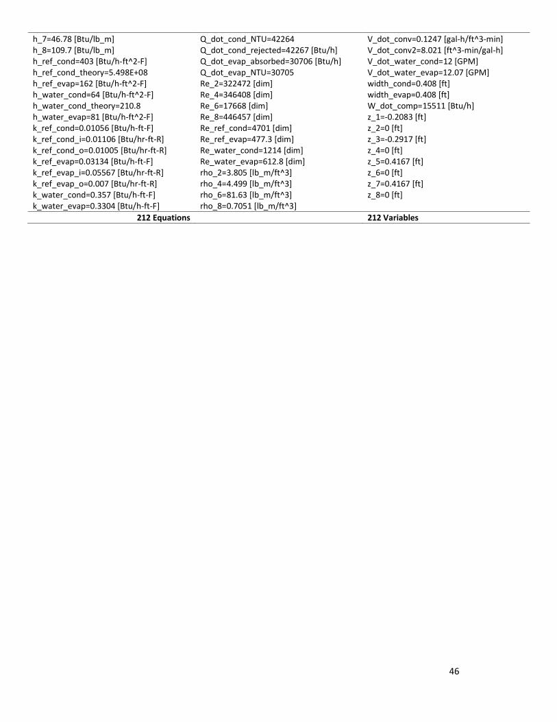
46
h_7=46.78 [Btu/lb_m] Q_dot_cond_NTU=42264 V_dot_conv=0.1247 [gal-h/ft^3-min] h_8=109.7 [Btu/lb_m] Q_dot_cond_rejected=42267 [Btu/h] V_dot_conv2=8.021 [ft^3-min/gal-h] h_ref_cond=403 [Btu/h-ft^2-F] Q_dot_evap_absorbed=30706 [Btu/h] V_dot_water_cond=12 [GPM] h_ref_cond_theory=5.498E+08 Q_dot_evap_NTU=30705 V_dot_water_evap=12.07 [GPM] h_ref_evap=162 [Btu/h-ft^2-F] Re_2=322472 [dim] width_cond=0.408 [ft] h_water_cond=64 [Btu/h-ft^2-F] Re_4=346408 [dim] width_evap=0.408 [ft] h_water_cond_theory=210.8 Re_6=17668 [dim] W_dot_comp=15511 [Btu/h] h_water_evap=81 [Btu/h-ft^2-F] Re_8=446457 [dim] z_1=-0.2083 [ft] k_ref_cond=0.01056 [Btu/h-ft-F] Re_ref_cond=4701 [dim] z_2=0 [ft] k_ref_cond_i=0.01106 [Btu/hr-ft-R] Re_ref_evap=477.3 [dim] z_3=-0.2917 [ft] k_ref_cond_o=0.01005 [Btu/hr-ft-R] Re_water_cond=1214 [dim] z_4=0 [ft] k_ref_evap=0.03134 [Btu/h-ft-F] Re_water_evap=612.8 [dim] z_5=0.4167 [ft] k_ref_evap_i=0.05567 [Btu/hr-ft-R] rho_2=3.805 [lb_m/ft^3] z_6=0 [ft] k_ref_evap_o=0.007 [Btu/hr-ft-R] rho_4=4.499 [lb_m/ft^3] z_7=0.4167 [ft] k_water_cond=0.357 [Btu/h-ft-F] rho_6=81.63 [lb_m/ft^3] z_8=0 [ft] k_water_evap=0.3304 [Btu/h-ft-F] rho_8=0.7051 [lb_m/ft^3]
212 Equations 212 Variables