DESCRIPTION OF WATER-SYSTEMS OPERATIONS IN THE … › wri › 1985 › 4092 › report.pdf ·...
79
DESCRIPTION OF WATER-SYSTEMS OPERATIONS IN THE ARKANSAS RIVER BASIN, COLORADO By P.O. Abbott U.S. GEOLOGICAL SURVEY Water-Resources Investigations Report 85-4092 Prepared in cooperation with the SOUTHEASTERN COLORADO WATER CONSERVANCY DISTRICT and the U.S. BUREAU OF LAND MANAGEMENT Lakewood, Colorado 1985
Transcript of DESCRIPTION OF WATER-SYSTEMS OPERATIONS IN THE … › wri › 1985 › 4092 › report.pdf ·...

DESCRIPTION OF WATER-SYSTEMS OPERATIONS
IN THE ARKANSAS RIVER BASIN, COLORADO
By P.O. Abbott
U.S. GEOLOGICAL SURVEY
Water-Resources Investigations Report 85-4092
Prepared in cooperation with the
SOUTHEASTERN COLORADO WATER CONSERVANCY DISTRICT and the
U.S. BUREAU OF LAND MANAGEMENT
Lakewood, Colorado 1985
UNITED STATES DEPARTMENT OF THE INTERIOR
DONALD PAUL HODEL, Secretary
GEOLOGICAL SURVEY
Dallas L. Peck, Director
For additional information write to:
Colorado District Chief U.S. Geological Survey, MS 415 Box 25046, Denver Federal Center Lakewood, CO 80225
orPueblo Subdistrict Chief U.S. Geological Survey P.O. Box 1524 Pueblo, CO 81002
Copies of this report can be purchased from:
Open-File Services Section Western Distribution Branch U.S. Geological Survey, MS 306 Box 25425, Denver Federal Center Denver, CO 80225
Telephone (303) 236-7476

CONTENTS
PageGlossary----------------- ---------------------------------------------- vAbstract---------------------------------------------- ----------------- iIntroduction---- ------------------------------------ _________________ i
Location of study area-------- ___-_________--------------_-_------ iPurpose and scope------------------------ ------ _________________ 3Acknowledgments---------------------------------- _________________ 4
Geographic setting------- --------- ________________ _________________ 4Population---------------------------------------------- -_-__----_ 4Physiography and climate------------------------ ------------- --- 4Drainage---------------------- ------------------------------------ 5
History of water development---------------- --------------------------- gWater-systems operations---------------------------------- ------------- 10
Municipal systems------------- - -------------- _________________ nCity of Colorado Springs--------------------------------------- 11City of Pueblo 25City of Trinidad 27City of Walsenburg 29
Irrigation systems-------------------------------------------------- 31Arkansas River------------------------------------------------- 32Arkansas River tributaries------------------------------------- 36
Wet Mountain Valley------------------------ _--_____-____ 35Fourmile, Hardscrabble, and Beaver Creeks----------------- 36Fountain Creek-- ---------------------------------------- 37St. Charles River 37Huerfano River--------------- -------- _________________ 37Cucharas River------------------------- ----_--__-__-____ 38Apishapa River-------------------------------------------- 39Purgatoire River--------------------------- _____________ 39
Industrial system: CF&I Steel Corporation-------------------------- 41Multipurpose systems------------------------------------------------ 43
Fryingpan-Arkansas Project------------------------------------- 43Arkansas River Compact----------------------------------------- 47Trinidad Dam and Reservoir Project----------------------------- 48Twin Lakes Project---------------------------- ----- -------- 49
Use of the report---------------------------------------------- -------- 51References------ ------- ______________________________________________ 51Supp1ementa1 data-------- __-______------------------------------------- 53
Operating plan (Pueblo Reservoir) winter water year 1982-83--------- 54Resolution concerning an operation plan for John Martin Reservoir--- 55
ILLUSTRATIONS
Plate 1. Map of Arkansas River basin in Colorado showing location ofconduits, tunnels, water districts, and general location of selected text figures where data are shown at a larger scale------------------------------------ ---- ------- in pocket
2. Map of Arkansas River basin in Colorado showing location ofselected ditch headgates and reservoirs--------------- in pocket
111
CONTENTS
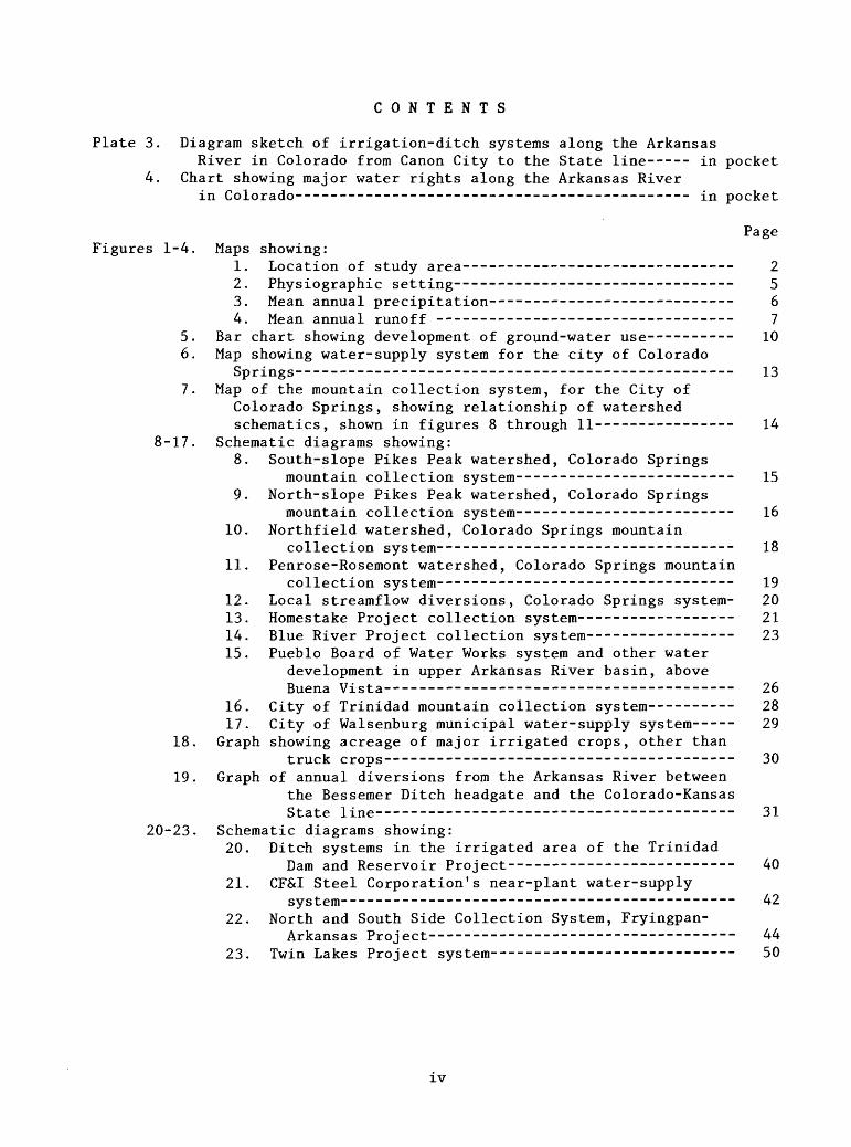
Plate 3. Diagram sketch of irrigation-ditch systems along the ArkansasRiver in Colorado from Canon City to the State line----- in pocket
4. Chart showing major water rights along the Arkansas Riverin Colorado--------------------------------------------- in pocket
Page Figures 1-4. Maps showing:
1. Location of study area------------------------------- 22. Physiographic setting-------------------------------- 53. Mean annual precipitation---------------------------- 64. Mean annual runoff ---------------------------------- 7
5. Bar chart showing development of ground-water use---------- 106. Map showing water-supply system for the city of Colorado
Springs-------------------------------------------------- 13
7. Map of the mountain collection system, for the City of Colorado Springs, showing relationship of watershed schematics, shown in figures 8 through 11--- ----------- 14
8-17. Schematic diagrams showing:8. South-slope Pikes Peak watershed, Colorado Springs
mountain collection system------------------------- 15
9. North-slope Pikes Peak watershed, Colorado Springsmountain collection system------------------------- 16
10. Northfield watershed, Colorado Springs mountaincollection system---------------------------------- 18
11. Penrose-Rosemont watershed, Colorado Springs mountaincollection system---------------------------------- 19
12. Local streamflow diversions, Colorado Springs system- 2013. Homestake Project collection system------------------ 2114. Blue River Project collection system----------------- 23
15. Pueblo Board of Water Works system and other water development in upper Arkansas River basin, above Buena Vista---------------------------------------- 26
16. City of Trinidad mountain collection system---------- 2817. City of Walsenburg municipal water-supply system----- 29
18. Graph showing acreage of major irrigated crops, other thantruck crops---------------------------------------- 30
19. Graph of annual diversions from the Arkansas River between the Bessemer Ditch headgate and the Colorado-Kansas State line----------------------------------------- 31
20-23. Schematic diagrams showing:20. Ditch systems in the irrigated area of the Trinidad
Dam and Reservoir Project-------------------------- 40
21. CF&I Steel Corporation's near-plant water-supplysystem i\2.
22. North and South Side Collection System, Fryingpan-Arkansas project----------------------------------- 44
23. Twin Lakes Project system---------------------------- 50
IV
CONTENTS
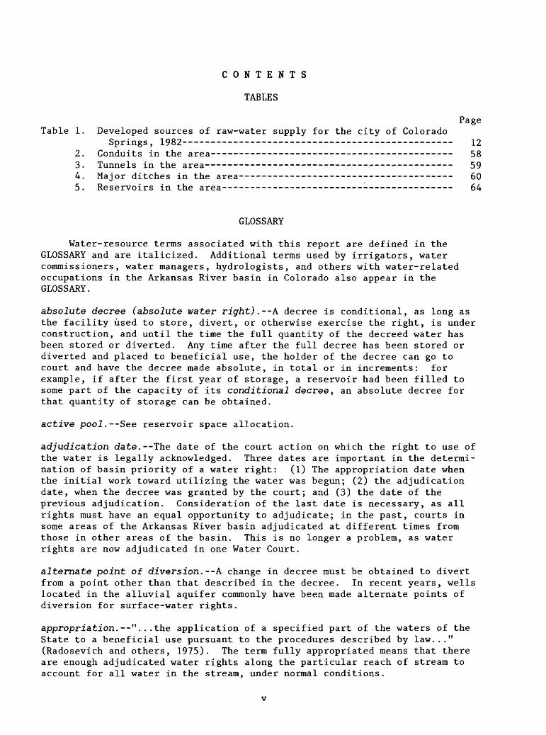
TABLES
Page Table 1. Developed sources of raw-water supply for the city of Colorado
Springs, 1982 122. Conduits in the area ---------------------- _________________ 553. Tunnels in the area-------------------------------------------- 594. Major ditches in the area------------------- --_---_----- --- 605. Reservoirs in the area---------------------- ----------------- 64
GLOSSARY
Water-resource terms associated with this report are defined in the GLOSSARY and are italicized. Additional terms used by irrigators, water commissioners, water managers, hydrologists, and others with water-related occupations in the Arkansas River basin in Colorado also appear in the GLOSSARY.
absolute decree (absolute water right). A decree is conditional, as long as the facility used to store, divert, or otherwise exercise the right, is under construction, and until the time the full quantity of the decreed water has been stored or diverted. Any time after the full decree has been stored or diverted and placed to beneficial use, the holder of the decree can go to court and have the decree made absolute, in total or in increments: for example, if after the first year of storage, a reservoir had been filled to some part of the capacity of its conditional decree, an absolute decree for that quantity of storage can be obtained.
active pool.--See reservoir space allocation.
adjudication date.--The date of the court action on which the right to use of the water is legally acknowledged. Three dates are important in the determi nation of basin priority of a water right: (1) The appropriation date when the initial work toward utilizing the water was begun; (2) the adjudication date, when the decree was granted by the court; and (3) the date of the previous adjudication. Consideration of the last date is necessary, as all rights must have an equal opportunity to adjudicate; in the past, courts in some areas of the Arkansas River basin adjudicated at different times from those in other areas of the basin. This is no longer a problem, as water rights are now adjudicated in one Water Court.
alternate point of diversion.--A change in decree must be obtained to divert from a point other than that described in the decree. In recent years, wells located in the alluvial aquifer commonly have been made alternate points of diversion for surface-water rights.
appropriation.--"...the application of a specified part of the waters of the State to a beneficial use pursuant to the procedures described by law..." (Radosevich and others, 1975). The term fully appropriated means that there are enough adjudicated water rights along the particular reach of stream to account for all water in the stream, under normal conditions.
called out. The demand that a junior right cease diversion, in order that sufficient water be available to the senior right.
canal.--An artificial waterway for the delivery of water; synonymous with "ditch" in the Arkansas River basin.
change in water right. "...a change in the type, place, or time of use; a change in the point of diversion; a change from a fixed point of diversion to alternate or supplemental point of diversion; a change in means of diversion; a change in the place of storage; a change from direct application to storage and subsequent application; a change from storage and subsequent application to direct application; a change from a fixed place of storage to alternate places of storage; a change from alternate places of storage to a fixed place of storage; or any combination of such changes. The term "change of water right" includes changes of conditional water rights as well as changes of (absolute) water rights..." (Radosevich and others, 1975).
conditional water right (conditional decree).--"...a right to perfect a water right with a certain priority upon the completion with reasonable diligence of the appropriation upon with such water right is to be based..."(Radosevich and others, 1975) see absolute decree.
conduit.--As used in this report, a closed duct or pipe for transporting water, a pipeline, or aqueduct.
conservation pool.--See reservoir-space allocation.
dead-storage pool.--See reservoir-space allocation.
direct-flow water right.--See water right. A direct-flow water right requires that the water be put to immediate beneficial use, as opposed to a storage right, which allows storage of a set volume of water for later use. Direct- flow water rights are described by a rate of diversion, such as cubic feet per second, gallons per minute, or (rarely) miners' inches. (The latter two have been converted to cubic feet per second in recent tabulations.)
ditch. Used here synonymously with "canal."
diversion or divert.--"...removing water from its natural course or location, or controlling water in its natural course or location, by means of a ditch, canal, flume, reservoir, bypass, pipeline, conduit, well, pump, or other structure device..." (Radosevich and others, 1975).
Division Engineer. The State of Colorado is divided into seven water divi sions under the State Engineer. Each water division is administered by a Division Engineer, who is responsible for administering the water rights in the division. The division is further divided into water districts, which are administered by water commissioners directly responsible to the Division Engineer. The Arkansas River basin constitutes Division 2.
due diligence. The holder of a conditional water right must prove to the water court once every 4 years that he or she is working with reasonable diligence toward the appropriation of that right; for example, he or she is working toward the construction of the system, reservoir, or canal, required to regulate the water.
vi
economic life of a reservoir.--In project planning, a feasibility study is made for any proposed reservoir. As a part of this study, consideration is given to the decrease of storage space within the reservoir by the deposition of sediment. The determination must be made that, during some period, the economic life of the reservoir, the economic benefits derived from storage in the reservoir, or flood protection by the reservoir are greater than the cost of constructing and maintaining the reservoir. The "useful life" of the reservoir usually extends far past the economic life.
evaporation charge.--If evaporation from the water surface of an on-channel reservoir were not accounted for, would constitute a loss to the stream on which the reservoir is built. To offset this loss of public waters, the daily rate of evaporation is measured (usually by a class A pan): a pan factor is applied to convert pan evaporation to lake-surface evaporation, and this rate is applied to that day's lake-surface area to compute the day's evaporation. Allowance is made for the evaporation that would have taken place had the lake not been present, and the resulting volume is released to the river from the storage account occupying the lake. The evaporation charge is administered in the Arkansas River basin by the Division Engineer, Colorado Water Division 2.
exchange. --A water exchange is possible by diverting water at one point in the river system, and replacing a like quantity of water from storage or trans- mountain diversions at another point in the system. To be legal, no party can be injured by the diversion. For example, an exchange is made to enable use of Lake Meredith water by irrigators who have rights to water diverted by the Colorado Canal. As Lake Meredith is downgrade from most land irrigated by water diverted by the canal, water is diverted from the river at the Colorado Canal headgate, and replaced, made whole, from storage through the Meredith Outlet Canal, which enters the river a few miles downstream from the headgate. Sufficent flow must be left in the river downstream from the Colorado Canal headgate to satisfy any senior rights between the headgate and the outlet canal. Exchanges can be made upstream or downstream from the point of use. River-transit losses are accounted for in the exchange.
flood"control pool.--See reservoir-space allocation.
flood right.--Said of a very junior right, one that is in priority only during flooding or during a free river.
free river.--A local term used to describe a condition where the flow of the river is sufficient to satisfy all vested rights, and diversions from the river can be made without possibility of injury to any senior right. In the Arkansas River basin in Colorado, this condition seldom exists, except during flooding.
futile call.--If, in the opinion of the Division Engineer, there is no possibility that water called out by a downstream senior right will reach the headgate of that right, the Division Engineer has the discretion (on the basis of paragraph 37-92-502(2) of the Water Right Determination and Administrtion Act of 1969) of not honoring the call and allowing the upstream junior right to continue diversion.
VII

green water. --A local term for water released from a major reservoir, refer ring to the absence of sediment in the water. Also, reservoir water with a lot of algae.
headgate. --The point on the stream at which water is diverted. A headgate can be a simple board structure on the stream bank, or a complex hydraulic struc ture consisting of radial gates and many other devices.
in priority.--See priority system.
inviolate space.--Inviolate reservoir storage space refers to space allocated to a single purpose, usually flood control, which cannot be infringed on for other uses, not even sediment accumulation. To keep the space inviolate, the elevation of the top and bottom of the various pools must be redefined periodically. For this purpose, reservoir-sedimentation surveys are conducted after set periods of time, and after major floods.
irrigation pool.--See reservoir-space allocation.
joint-use pool.--See reservoir-space allocation.
junior right. --A relative term describing a water right with a priority less than that of a "senior right." In general use in the Arkansas River basin, junior rights refer to those water rights seldom in priority; senior rights refer to those water rights usually in priority.
made whole.--To leave the river in the condition it would have been had the exchange, reservoir release, or other action not taken place. (Robert Jesse, Colorado Water Division 2 Engineer, written commun., August 23, 1984.)
native water.--As used in this report, water naturally occurring in the basin in which it is found; not imported from outside the basin.
off-stream reservoir (off-channel reservoir).--A surface-water storage reser voir located outside the channel of the stream that constitutes the principal source of the water stored in the reservoir. Off-stream storage is supplied by a ditch or conduit, with the headgate located on a stream other than that in which the reservoir is situated. Those off-stream reservoirs located in the channel of a tributary might store minor quantities of the waters of that tributary as well. Like other reservoirs in Colorado, a storage right is required that describes the source, quantity, use, and priority of all water stored.
on-stream reservoir (on-channel reservoir).--An on-stream reservoir derives most of the water stored from the stream on which the reservoir is located. A storage right is required.
penciled out.--A local term used to describe the transfer of water from the "compact pool" (conservation pool) to the "agreement pool" (accounts) in John Martin Reservoir. See Arkansas River Compact section.
penstock.--The conduit that conveys water under pressure to the turbines of a hydroelectric powerplant.
Vlll
plan for augmentation. "...a detailed program to increase the supply of water available for beneficial use in a division or part thereof by the development of new or alternate means or points of diversion; by pooling of water resources; by water-exchange projects, by providing substitute supplies of water; by the development of new sources of water; or by any other appropriate means. "Plan for Augmentation" does not include the salvage of tributary waters by the eradication of phreatophytes, nor does it include the use of tributary water collected from land surfaces that have been made impermeable, thereby increasing the runoff, but not adding to the supply of tributary water..." (Radosevich and others, 1975).
power pool.--See reservoir-space allocation.
previous adjudication date.--A date listed in the tabulation of all water rights that is significant, in that, regardless of the priority date assigned, all rights adjudicated on a given date are junior to all rights adjudicated at an earlier date. The opportunity to adjudicate is taken into consideration in establishing basin-wide priorities.
priority system.-- In the United States, two major types of water-law doctrines occur. The riparian doctrine holds that waters are appurtenant to the land through which they flow. The appropriation doctrine holds that the waters within a State are the property of the public, with a vested right to the use of the appropriation: the first in time to use the water is first in right. It is the establishment of the order of the first in time being first in right that has been designated priority, and the system under which these water rights are administered has been referred to as the "priority system."
raw water.--In this report, raw water refers to untreated municipal or industrial water supplies.
recreation pool.--See reservoir-space allocation.
replacement storage. --A feature of transmountain diversions in Colorado. The purpose of replacement storage is to store water during that part of the year when runoff is at a peak and all rights are being satisfied downstream in the basin, and to hold these waters for later release. Later release comes during that part of the year when the snowmelt peak has ended, and runoff in the basin is at a much slower rate. Water upstream from the transmountain- diversion system in excess of minimum fish-flow requirement might still be diverted, regardless of the date of the call on the river from which the diversions are made, provided a quantity equal to that diverted from the basin be released from replacement storage to meet the demands of senior rights downstream.
reservoir-space allocation.--Federally constructed reservoirs serve multiple purposes. Space in these reservoirs is allocated to the various purposes. This space, called pools, usually is defined by the bottom and the top eleva tion of the pool. Sediment accumulation necessitates periodic redefinition of these top and bottom elevations. Terminology will vary slightly with the agency operating the reservoir, and with the chief purpose for which the reservoir was constructed. Space-allocation terms used in reservoirs located
IX

in the Arkansas River basin in Colorado include: The minimum pool or perma nent pool is the pool below which water is not withdrawn. It can include a dead-storage pool below the elevation of the outlet works, or a recreation poo1 , that is held at a certain level to provide scenic, fishing, boating, or other recreational opportunities. The minimum pool might be held at a certain level to enable delivery of water to a given required elevation. Above the permanent pool, is the active poo 1 , where water can be regulated. The conser vation poo.Z is used to store water for later use. If the use is for irriga tion, the conservation pool can be considered the irrigation poo1 ; under other uses, it might be the power pool or the municipal pool. The flood-control pool (flood pool) is considered inviolate space, and it cannot be decreased during the economic life of the reservoir by sedimentation. Surcharge is water temporarily stored above the lip of the uncontrolled spillway, which helps decrease the peak of very large floods. Sediment pool is the space reserved for accumulation of sediment throughout the economic life of the reservoir, (usually 75 to 100 years). Because water surfaces of most on- stream reservoirs are constantly changing, the sediment is not deposited below a specific elevation; therefore, the top and bottom of the sediment pool are not defined by elevation. The joint-use pool is a pool used for more than one purpose. For example, the joint-use pool in Trinidad Reservoir refers to the 39,000 acre-foot sediment pool, which, before it is occupied by sediment depo sition, will be used to regulate irrigation supplies. In Pueblo Reservoir, the joint-use pool refers to 66,000 acre-feet, which, between the dates of April 15 and October 31, is inviolate flood space; during the rest of the year, this space can be used to regulate irrigation supplies. Reservoir-space allocation is revised with sediment accumulation; thus, one might encounter such terms as initial, 50-year, and 100-year allocations.
riparian doctrine.--A form of water law that gives the owners of the land adjacent to the water course equal rights to the use of the water.
river call. --Under normal flow conditions, the Arkansas River call date is simply the decree date of the most junior diversion, drawing a part of its decreed rights from the Arkansas River. The date is determined by the Division Engineer in conjunction with Water Commissioners of water districts concerned, and affects diversions in Water Districts 10, 11, 12, 13, 14, 15, 17 and 67. It is based on flows at the Portland, Pueblo, Avondale, and La Junta streamflow-gaging stations, and the decreed diversions in Water Districts 14 and 17. Advanced notice of increasing and decreasing river flow is provided by the Granite and Wellsville streamflow-gaging stations. Under certain conditions, two distinct call dates may exist: one for the river upstream from Pueblo, and a second for the river downstream from Pueblo. The date downstream will be later, because of substantial inflow or return flow to the river. The call date on tributaries is determined by both the river call and the flow in the specific tributary. For example, although the Arkansas River call may be 1882, an 1879 right on a certain tributary might not be able to divert, because all flow of that tributary is going to satisfy a 1875 right from the same stream. (Jim Kasic, Assistant Division Engineer, Division 2, oral commun., 1983.)
sediment pool.--See reservoir-space allocation.
senior right. --A relative term referring to a right with an earlier priority. See "junior right."
shrink. --A local term used to describe the decrease of an entity's water supply by any one of a number of causes. It has been used in reference to: (1) The transportation loss charged in routing a reservoir release down a river channel; (2) the pro-rata share from the participants of the Pueblo Reservoir Winter Water Program (see discussion under Fryingpan-Arkansas Project; to provide the agreed share to an entity not receiving a full share; and (3) the decrease of reservoir-storage accounts by evaporation.
slick water. --A local term used to describe high flow from the Apishapa River into the Arkansas River. Because of the large concentration of sediment in Apishapa flood flows, the water is undesirable for irrigation, and, when pos sible, is not diverted.
sluice.--As used most commonly in the Arkansas River valley in Colorado, this local term refers to the act of washing sand and other sediments from canals back into the stream from which they were diverted. Most canals are equipped with one or more sluice gates along their length, one almost always just down- ditch from the headgate, and up ditch from the measuring section.
sluice box.--In placer mining, a long inclined trough paved with riffles for catching gold from water-borne gravel washed through the passage.
storage.--"...the impoundment, possession, and control of water by means of a dam..." (Radosevich and others, 1975). To retain possession of stored waters requires a storage right (storage decree).
storage right.--See water right. A storage right allows the holder to store a given volume of water each year for beneficial use later in the season or in following seasons.
surcharge.--See reservoir-storage allocation.
tailwater. --Excess surface water draining from an irriated field or returning to natural channels from the downgradient end of an irrigation ditch. It also is the water in a channel immediately downstream from a dam, mill, or power- plant.
transit loss.--Colorado water law allows the owner of a reservoir to use a natural stream to convey stored water to the place of use, provided that allowance is made for losses that occur while the water is in the natural stream. The State Engineer has the responsibility of determining these losses (Luckey and Livingston, 1975).
transmountain diversions.--The importation of water originating in one river basin from that basin into another river basin. The diversion is by means of a ditch, canal, or conduit through a topographic saddle in the divide between the basins, or by means of a tunnel through the basin divide. A water right is required in the basin from which the diversion is made, and a record of imports is made at the outlet end of the conveyance structure in the receiving basin.
XI

trap efficiency (reservoir).--The percentage of the sediment load that is retained in a reservoir to total sediment load flowing into the reservoir. Trap efficiency depends on reservoir size, on reservoir shape, on the nature of the sediment entering the reservoir, on reservoir operation, and on the ratio of storage capacity to inflow volume.
useful life of a reservoir.--See economic life of a reservoir.
waste.--As used in the Arkansas River basin and in this report, waste is a local term that refers to water turned back into the source stream or lake unused. Waste gates are structures located along canals to enable release to the river, usually for the purpose of sluicing sand from the canal. It has no reference to nonbeneficial use of water. Used water, as in a manufacturing process, also is termed waste.
water right. --"...a right to use in accordance with its priority a certain part of the waters of the State by reason of appropriation of the same..." (Radosevich and others, 1975).
METRIC CONVERSION
The inch-pound units used in this report may be converted to International System of Units (SI) by the following conversion factors:
Multiply
acreacre-footcubic foot per secondfootinchmilesquare milemillion gallons per day
By
0.4047 ,233
0.02832 0.3048
25.40 1.609 2.590 4.381X10
-2
To obtain
hectarecubic metercubic meter per secondmetermillimeterkilometersquare kilometercubic meters per second
XII
DESCRIPTION OF WATER-SYSTEMS OPERATIONS IN THE ARKANSAS RIVER BASIN, COLORADO
By P.O. Abbott
ABSTRACT
To facilitate a current (1985) project modeling the hydrology of the Arkansas River basin in Colorado, a description of the regulation of water in the basin is necessary. The geographic and climatic setting of the Arkansas River basin that necessitates the use, reuse, importation, and storage of water are discussed. The history of water-resource development in the basin, leading to the present complex of water systems, also is discussed. Munici pal, irrigation, industrial, and multipurpose water systems are described. System descriptions are illustrated with schematic line drawings, and supple mented with physical data tables for the lakes, tunnels, conduits, and canals comprising the various systems. Copies of criteria, under which certain of the water systems operate, are included.
INTRODUCTION
The water in the Arkansas River basin is a valuable resource that trans forms fertile but dry lands into productive agricultural areas. Historically, in this area, man used and reused available water, stored water in times of more abundant supply for use in times of low streamflow, imported water from nearby drainage basins where supply was greater and demand less, and utilized the ground-water aquifer in the valley alluvium. A comprehensive surface- water/ground-water model of the Arkansas River basin in Colorado currently (1985) is being developed by the U.S. Geological Survey. To design this model, the description of water-systems operations in the basin is essential. The operations of the more complex systems in the valley are described here, including municipal systems, irrigation systems, an industrial system, and multipurpose systems.
Location of Study Area
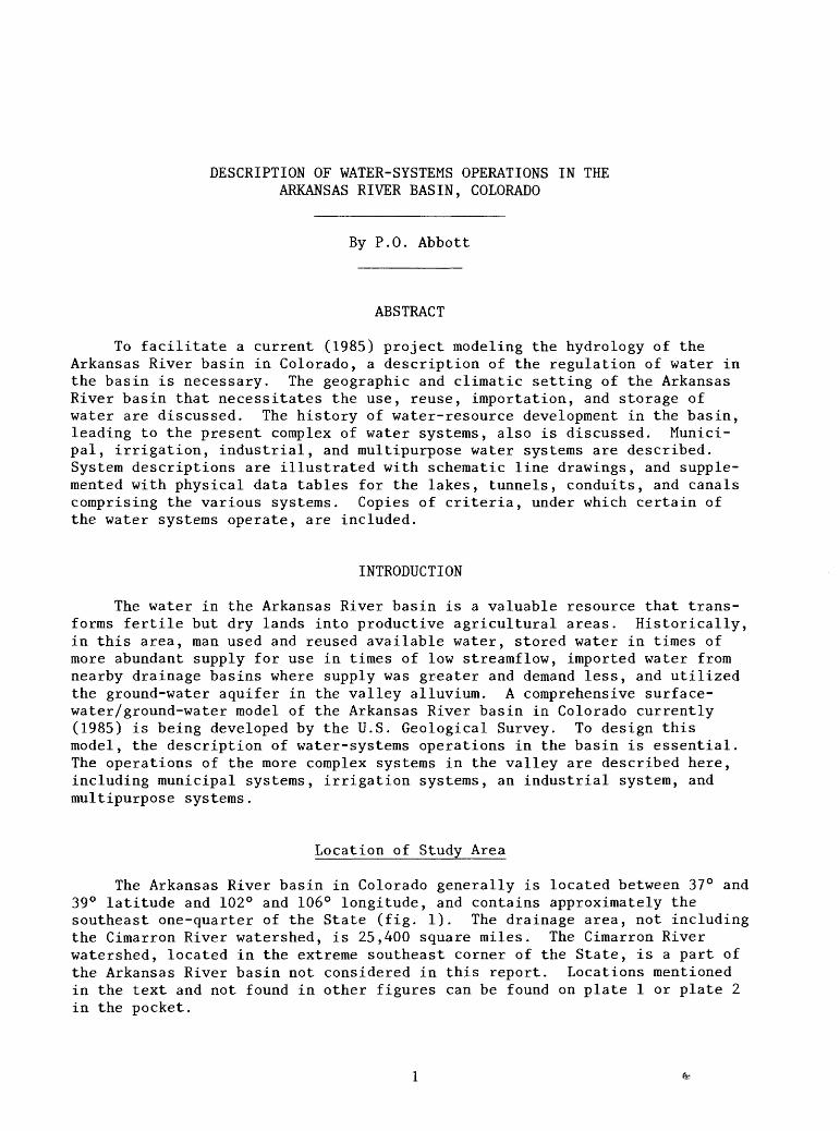
The Arkansas River basin in Colorado generally is located between 37° and 39° latitude and 102° and 106° longitude, and contains approximately the southeast one-quarter of the State (fig. 1). The drainage area, not including the Cimarron River watershed, is 25,400 square miles. The Cimarron River watershed, located in the extreme southeast corner of the State, is a part of the Arkansas River basin not considered in this report. Locations mentioned in the text and not found in other figures can be found on plate 1 or plate 2 in the pocket.
r
Tw
in
La
kes
37
0
NE
W M
EX
ICO
10
4<
25
50
37° 7
5 M
ILE
S
0 25
50
75
KIL
OMET
ERS
Fig
ure
1.-
-Lo
ca
tio
n
of
stu
dy
area.

The terminology used in this report currently (1985) is used among irrigators, water commissioners, water managers, hydrologists, hydrographers, water-resource technicians, and others with water-related occupations in the Arkansas River basin of Colorado. Because some of these terms are not widely used in other parts of the Nation, a glossary has been provided.
Purpose and Scope
In a semiarid region like the Arkansas River basin of Colorado, water that originates in the basin, and water that is imported from outside the basin, are used and reused many times. The U.S. Geological Survey currently (1985) is developing a comprehensive surface- and ground-water model of the Arkansas River drainage basin in Colorado. To accomplish this task, a description of the water-systems operations in the basin is essential. This report describes the system of surface-water diversions, the transmountain imports and exports, the regulation of flows by on-stream and off-stream reservoirs, and the various water exchanges that are used in the Arkansas River as of 1983.
Administration of water in Colorado is the responsibility of the Colorado State Engineer; administration of Arkansas River water is delegated to the Division Engineer, Colorado Water Division 2, who is assisted by Water Commissioners in each of the 13 local water districts (pi. 1). Colorado Water Division 2 covers the entire Arkansas River basin in Colorado. Regulation of water is provided by the State Constitution and laws and statutes of the State, and by their interpretation in numerous court decisions. This report is not concerned with the legal aspects of systems operation, only the result of that legal regulation. The operations of the larger systems, those in which sizable quantities of water are involved, are described, and the more complex operations are described in detail, regardless of their water quanti ties. For example, an irrigation ditch with an early direct"flow water right that diverts water from a river and transports it directly by gravity in a canal to nearby farm plots for irrigation, is a simple operation, regardless of the quantity of water involved. If, however, the water was diverted from the river at the canal headgate, at a time when the canal's direct flow right was not in priority, and the river then was made whole at some point down stream by release of stored water from the diverter's storage right, then that complex system may be given a more thorough description in this paper, regard less of the volume of water involved.
Recently, a profusion of so-called "plans for augmentation" has devel oped. Although these plans are sufficiently complex to warrant detailed description, most of them involve only minor quantities of water; therefore, their description is not included in this paper.
In describing the water systems in operation in the Arkansas River basin, constant reference is made to canals, ditches, tunnels, conduits, dams, and reservoirs, and some statistical description of these various features is given. A more detailed description of each of these features (location, size, purpose, owner, and so forth) is provided in the Supplemental Data section at the end of the report.

Acknowledgments
A report of this nature requires information and cooperation from many people. The author would like especially to thank the following: Ralph Adkins and Joseph Mahaney, CF&I Steel Corporation; Roger L. O'Hara, Pueblo Board of Water Works; James Fernandez, City of Trinidad Department of Utili ties; Edward Martinez, Colorado Springs Department of Utilities; Carmel A. Garlutzo and Patricia Hines, Purgatoire River Water Conservancy District; Charles L. (Tommy) Thomson, Southeastern Colorado Water Conservancy District; Thomas A. Gibbens, Fryingpan-Arkansas Project; Jack McCullough, Twin Lakes Project; and Raymond Harriman, Walsenburg Water Department. Thanks also go to Robert Jesse, Division Engineer Colorado Water Division 2, and to James F. Kasic and Kenneth Cooper, Assistant Division Engineers, William Howland, Engi neering Technician II, and Thomas C. Simpson, Hydrographer. The following Water Commissioners were extremely helpful: Robert Ermel, Water District 10; Bruce Smith, Water District 11; George Wichmann, Water District 12; Donald K. Stuart, Water District 13; George Ridenour, Water Districts 14 and 15; Robert Brgoch, Water District 16; Donald L. Taylor, Water District 17; Leonard Tru- jillo, Water District 18; Henry D. Marquez, Water District 19; Lane Hackett, Water District 67; and Augustine Garcia (deceased), Water District 79. The author is solely responsible for any errors found in this report.
GEOGRAPHIC SETTING
Population
Population in the area was determined by the 1980 census (U.S. Bureau of the Census, 1980) to be 567,000, or almost 20 percent of the total population of Colorado. Most of the population is located along the base of the mountains in two counties: El Paso County (55 percent), and Pueblo County (22 percent). Much of the remainder of the population is concentrated along the Arkansas River.
Physiography and Climate
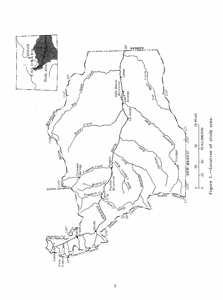
The physiographic setting of the study area has been described by Fenneman (1931). The western part of the basin, approximately west of the 105° parallel, is in the Southern Rocky Mountain Province. East of that line is the Great Plains Province, which is further divided into the Colorado Piedmont, north of a line paralleling, and about 25 miles south of, the river, and the Raton section, south of that line. The Colorado Piedmont is a late, mature to old, elevated plain; the Raton section is a trenched peneplain (fig. 2).
Climate in the study area is affected greatly by differences in eleva tion. It has been said that "The difference in average temperature between Pikes Peak and Las Animas, 90 miles to the southeast, is about the same as that between southern Florida and Iceland" (Berry, 1959).
EXPLANATION
PHYSIOGRAPHIC BOUNDARY
BASIN BOUNDARY
COLORADOlPIEDMONT
,J
NEW MEXICO ""104°
25 50 75 MILES ___i _____ i_________i
25 50 75 KILOMETERS
Figure 2.--Physiographic setting. (After Fenneman, 1931)
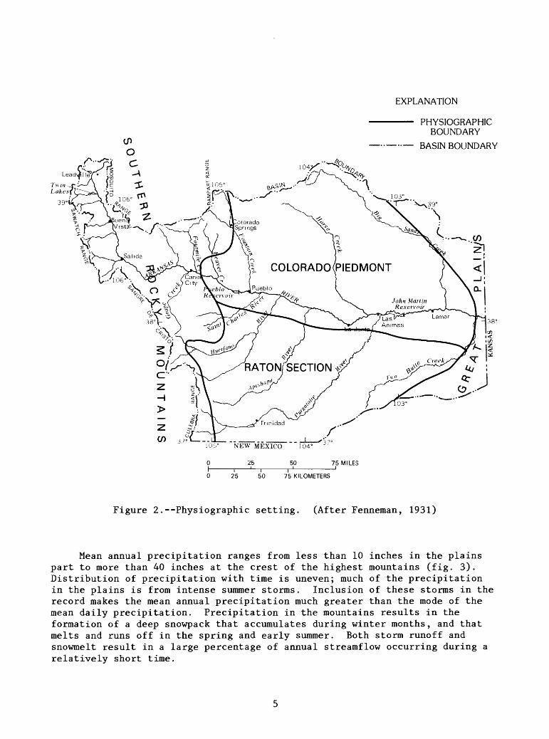
Mean annual precipitation ranges from less than 10 inches in the plains part to more than 40 inches at the crest of the highest mountains (fig. 3). Distribution of precipitation with time is uneven; much of the precipitation in the plains is from intense summer storms. Inclusion of these storms in the record makes the mean annual precipitation much greater than the mode of the mean daily precipitation. Precipitation in the mountains results in the formation of a deep snowpack that accumulates during winter months, and that melts and runs off in the spring and early summer. Both storm runoff and snowmelt result in a large percentage of annual streamflow occurring during a relatively short time.

EXPLANATION
LINE OF EQUAL MEAN ANNUAL PRECIPITATION- Interval, in inches, is variable
BASIN BOUNDARY
ARKANSAS f DRAINAGE
105° NEW MEXICO 104
From U.S. Weather Bureau, 1959
0 25 50 75 KILOMETERS
Figure 3.--Mean annual precipitation.
Drainage
The Sawatch, Culebra, and Sangre de Cristo Ranges form the western boundary of the Arkansas River basin (pi. 1). The Sawatch Range separates the northern part of the basin from the headwaters of the Gunnison River, the Roaring Fork, and the Eagle River, all in the Colorado River basin, and the Culebra and Sangre de Cristo Ranges separate the southern part of the basin from the Rio Grande headwaters. The mountains in these three ranges are among the highest in the Nation, with 23 peaks more than 14,000 feet. Streambed elevation at the point the Arkansas River flows into Kansas is 3,350 feet.

Perennial streams in the area have their headwaters at high elevation. In the northern part of the Arkansas River upstream from Salida, most western tributaries originate in the Collegiate Peaks of the Sawatch Range. Texas and Grape Creeks flow from the crest of the Sangre de Cristo Range. Fourmile, Beaver, and Fountain Creeks originate on the slopes of Pikes Peak, another 14,000-foot mountain. Hardscrabble Creek and the St. Charles River originate in the Wet Mountains, with headwaters above 9,000 feet and 11,000 feet. The Huerfano, Apishapa, and Purgatoire Rivers have their headwaters in the Culebra Range. These streams all are sustained by mountain snowpack. Northern tribu taries of the Arkansas River downstream from Pueblo, Colo., originate on the Colorado Piedmont and are ephemeral, as are smaller southern tributaries between, or tributary to, the major southern perennial tributaries. Mean annual runoff decreases from more than 30 inches from the mountain peaks to less than 0.1 inch from the Colorado Piedmont, downstream from Pueblo (fig. 4).
EXPLANATION
0.5 LINE OF EQUAL MEANANNUAL RUNOFF Interval, in inches, is variable
- BASIN BOUNDARY
From U.S. Geological Survey, 1970
25 50 75 MILES
25 50 75 KILOMETERS
Figure 4.--Mean annual runoff.

HISTORY OF WATER DEVELOPMENT
Water development in the Arkansas River basin of Colorado can be divided into four distinct, progressive, generally chronological phases: (1) Develop ment of direct diversions; (2) development of water storage; (3) importation of water by transmountain diversion; and (4) development of ground water.
Earliest development was the diversion of water from a flowing stream for direct use, either to irrigate a farm plot, to wash gravel in a placer-mining operation, or to turn a mill wheel. The earliest appropriation date listed in Irrigation Division 2, March 31, 1859, is that of the Hicklin ditch on Greenhorn Creek. Evidence indicates that irrigation was being used at this location much earlier. Lieutenant E.G. Beckwith, traveling through the area with Captain John W. Gunnison's party in 1853, reported that the waters of Greenhorn Creek were diverted to water the fields of six Mexican families in the valley. And, while no mention was made of irrigation, George Frederick Ruxton, who passed through the area in 1847, found a settlement of French- Canadian hunters and their Indian wives farming the Greenhorn Valley (Taylor, 1963).
There is history of still earlier irrigation in the basin. In the valley of the Purgatoire River, just downstream from the present town of Trinidad, an irrigation ditch was dug by the Bents (of Bent's Fort fame) in 1847. A man named Hatcher operated the enterprise and the ditch has been called Hatcher ditch. After a short period, the ditch was abandoned. In 1864, this ditch was taken over and rehabilitated by John Lewelling. The Lewelling-McCormack Ditch is still in operation (McHendrie, 1928).
These early ditches irrigated small plots on the flood plain of the Arkansas River or its tributaries; they were operated by one or two farm units. Some ditches served the headgates of several farms, but all were located on the flood plain and required little or no engineering to get the water to the land. Many had no diversion dam, but relied on a headgate at stream level.
After all the irrigatable acres on the flood plain became occupied, irrigation began on the terraces above the river bottom. Getting water to the terraces was more difficult, requiring more engineering and more expense. To overcome these obstacles, a number of farm units would band together and form a mutual irrigation company. The area served by flood-plain and tributary ditches was of the magnitude of tens or hundreds of acres; the area served by mutual ditch companies was of the magnitude of thousands or tens of thousands of acres. To justify the expense of such an undertaking, these mutual compa nies commonly bought earlier water rights of the smaller ditches.
By the middle 1880's, the Arkansas River and its tributaries were fully appropriated for normal or average years. In most areas, water rights later than 1887 are little more than flood rights, and will not provide a dependable supply. However, water is available as high flow during snowmelt and after summer rainstorms. Also, flow occurs in the river at times other than the irrigation season. These flows have been diverted to fallow ground to recharge soil moisture and the ground-water system, and, to some extent, this practice still is followed. However, these early or late season and peak flows generally are not available to or wanted by direct-flow water rights, as these flows come at times inconvenient to farming operations, or at rates in excess of canal capabilities.

Water-storage rights were developed to use more fully the flow not avail able to direct diversions. Reservoirs, both on-stream and off-stream, were constructed to store water in excess of direct-flow water rights, and stream- flow outside of the irrigation season. Irrigation water is stored for later use during the growing season; municipal and industrial water is stored to meet a constant demand.
There is a legend that a placer miner established the first transmountain diversion in the Arkansas River basin; finding no water left in the stream to run his sluice box, the miner walked through a mountain saddle and found a full, flowing stream on the far slope. He dug a ditch through the saddle in the mountain crest to bring this water to his claim. Whatever the initial circumstances, transmountain diversions into the Arkansas River basin began around the turn of the 20th century, and are continuing to be developed today. These diversions vary in size and complexity from open ditches through low spots in the mountain-chain crest, to vast collection systems of tunnels, con duits, and storage reservoirs, that convey the water from the western slope to a single master tunnel, thence through the Continental Divide to the eastern slope. This complex diversion is possible, because there is unappropriated water in the western part of Colorado. Colorado's western slope is not able to use all its share of water, assigned by the Upper Colorado River Compact.
Ground water has been used in the basin from the onset of settlement. The earliest settlers dug wells, and later erected windmills; stock wells long have been in use in the uplands. After all the inexpensive, gravity-flow sources of surface water had been fully used, development of large-volume wells for irrigation, municipal, and industrial uses began. Estimated pumpage of ground water in the Arkansas Valley is shown in figure 5, and indicates a drastic increase in ground-water use during the 1950's. Withdrawal from allu vial aquifers in the basin increased to the point where effects on the river system became a problem. In 1969 the law governing use of water in Colorado was changed, making water rights from aquifers hydraulically connected to streams work in priority with surface-water rights (Radosevich and others, 1975).
Water development was not restricted to agricultural purposes. As cities and industries in the valley expanded, water supplies necessarily increased with them. The Colorado State Constitution gives preference to domestic and municipal use over industrial and agricultural use. As agricultural land is no longer farmed, the water supply that once served that land is used for other purposes. As technologies and economies continue to change, the priori ties of water use will continue to change. This change may not always be in one direction--from agricultural use toward municipal and industrial use. The recent national fuel crisis highlighted the fact that synthetic fabrics manu factured from petroleum products always might not be available readily, and the economy might have to depend on farm-grown fiber. Hydroelectric power, especially from low-head, run-of-the-river-type generators, increasingly is becoming attractive. Future economic development might change the type of water development in the Arkansas Valley.

DC
LU
DC LU
160,000
120,000
LU LU LL
cj 80,000DC
40,000
1935 1940 1945 1950 1955 1960 1965 1970 1975 1980 1985
Data prior to 1970 from Major and others, 1970
Figure 5.--Development of ground-water use.
WATER-SYSTEMS OPERATIONS
Water systems in the Arkansas River basin described here are those with complex operations, such as transmountain diversions, systems involving con siderable storage, or systems requiring exchanges to operate. These systems generally can be divided into four categories: municipal systems, irrigation systems, industrial systems, and multipurpose systems. A schematic diagram accompanies each of the following system descriptions. The general location of each of these schematic diagrams is outlined on plate 1 in the pocket. Plate 1 also shows many of the drainages and land features that are referenced throughout the text.
10
Municipal Systems
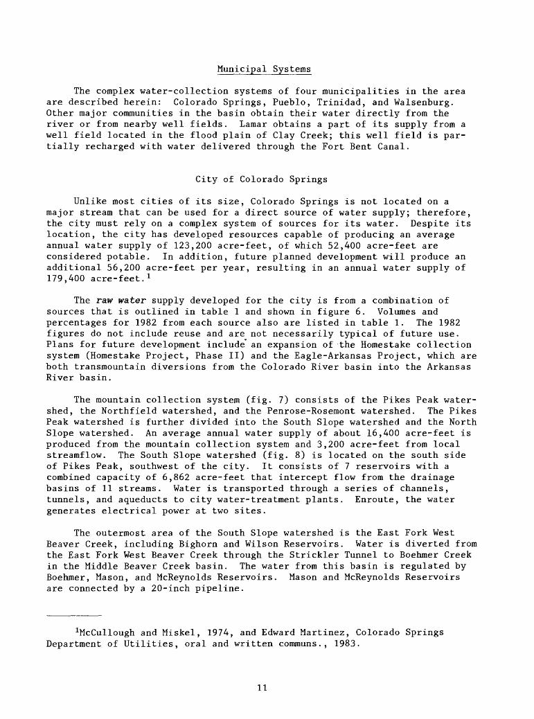
The complex water-collection systems of four municipalities in the area are described herein: Colorado Springs, Pueblo, Trinidad, and Walsenburg. Other major communities in the basin obtain their water directly from the river or from nearby well fields. Lamar obtains a part of its supply from a well field located in the flood plain of Clay Creek; this well field is par tially recharged with water delivered through the Fort Bent Canal.
City of Colorado Springs
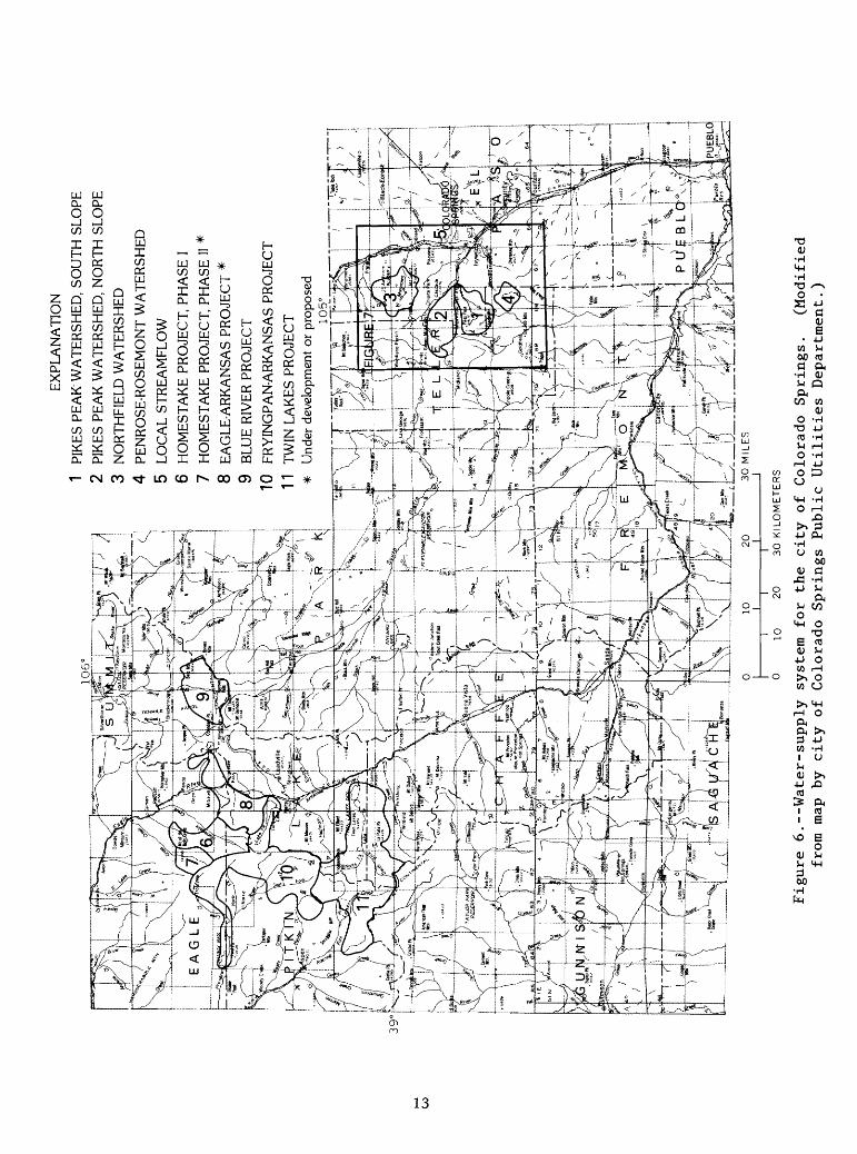
Unlike most cities of its size, Colorado Springs is not located on a major stream that can be used for a direct source of water supply; therefore, the city must rely on a complex system of sources for its water. Despite its location, the city has developed resources capable of producing an average annual water supply of 123,200 acre-feet, of which 52,400 acre-feet are considered potable. In addition, future planned development will produce an additional 56,200 acre-feet per year, resulting in an annual water supply of 179,400 acre-feet. 1
The raw water supply developed for the city is from a combination of sources that is outlined in table 1 and shown in figure 6. Volumes and percentages for 1982 from each source also are listed in table 1. The 1982 figures do not include reuse and are not necessarily typical of future use. Plans for future development include an expansion of the Homestake collection system (Homestake Project, Phase II) and the Eagle-Arkansas Project, which are both transmountain diversions from the Colorado River basin into the Arkansas River basin.
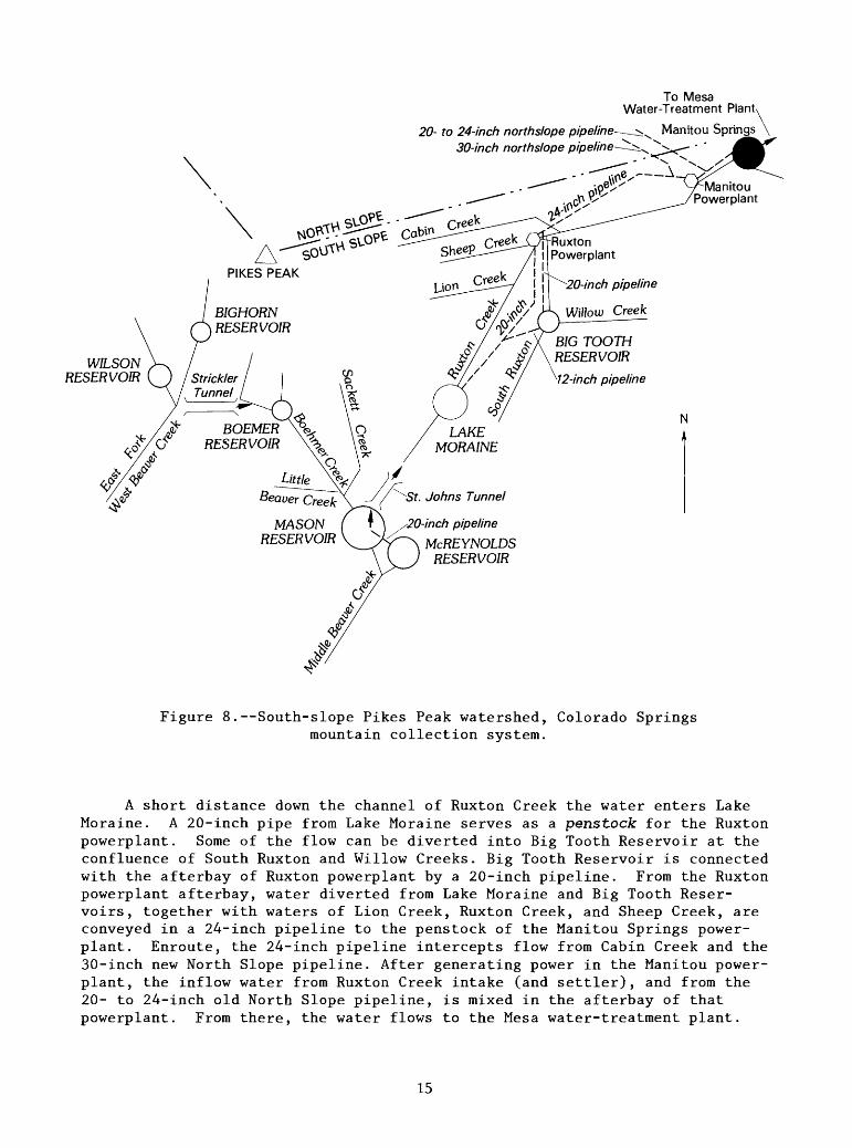
The mountain collection system (fig. 7) consists of the Pikes Peak water shed, the Northfield watershed, and the Penrose-Rosemont watershed. The Pikes Peak watershed is further divided into the South Slope watershed and the North Slope watershed. An average annual water supply of about 16,400 acre-feet is produced from the mountain collection system and 3,200 acre-feet from local streamflow. The South Slope watershed (fig. 8) is located on the south side of Pikes Peak, southwest of the city. It consists of 7 reservoirs with a combined capacity of 6,862 acre-feet that intercept flow from the drainage basins of 11 streams. Water is transported through a series of channels, tunnels, and aqueducts to city water-treatment plants. Enroute, the water generates electrical power at two sites.
The outermost area of the South Slope watershed is the East Fork West Beaver Creek, including Bighorn and Wilson Reservoirs. Water is diverted from the East Fork West Beaver Creek through the Strickler Tunnel to Boehmer Creek in the Middle Beaver Creek basin. The water from this basin is regulated by Boehmer, Mason, and McReynolds Reservoirs. Mason and McReynolds Reservoirs are connected by a 20-inch pipeline.
^cCullough and Miskel, 1974, and Edward Martinez, Colorado Springs Department of Utilities, oral and written communs., 1983.
11

Water is diverted from the Beaver Creek drainage into Ruxton Creek drainage via the St. Johns Tunnel. This tunnel diverts directly from Mason or McReynolds Reservoirs. Diversions through St. Johns Tunnel are limited to 18.9 cubic feet per second.
Table 1.--Developed sources of raw-water supply for the city of Colorado Springs, 1982
1982 YieldSource Acre-feet Percent of total
Surface Water
Mountain watersheds
Pikes Peak watershed 14,816 28.5South Slope------------------------------- ------North Slope
Northfield watershed 902 1.7Penrose-Rosemont watershed------------------ 650 1.3
Local streamflow
Fountain Creek--------------- ---- - ---- (with Pikes Peak watershed)Bear Creek 1,829 3.5 North and South Cheyenne Creeks
(South Suburban Water Company) 1,400 2.7 Sutherland Creek----------- -- ----------- ______
Transmountain water
Homestake Project 483 0.9Blue River Project 6,653 12.8Fryingpan-Arkansas Project------------ ---- 254 0.5Twin Lakes Project 23,802 45.8
Ground water 1,200 2.3Pinello Ranch--------------------------- ---- ------Hanna Ranch---- ----------------------------- - --- ____Venetucci Ranch------------------------------- ------ ____Cherokee Water District----------------- ---- ------
Reuse of imported water-
TOTAL 51,989 100.0
12
106
EX
PLA
NA
TIO
N
1 PI
KES
PE
AK
WA
TE
RSH
ED
, SO
UT
H S
LO
PE
2 PI
KES
PE
AK
WA
TE
RSH
ED
, N
OR
TH
SL
OPE
3 N
OR
TH
FIE
LD
WA
TE
RSH
ED
4
PEN
RO
SE-R
OSE
MO
NT
WA
TE
RSH
ED
5 L
OC
AL
ST
RE
AM
FLO
W
6 H
OM
EST
AK
E P
RO
JEC
T,
PHA
SE I
7 H
OM
EST
AK
E P
RO
JEC
T,
PHA
SE I
I *
8 EA
GLE
-AR
KA
NSA
S PR
OJE
CT
*
9 B
LUE
RIV
ER P
RO
JEC
T
10
FRY
ING
PAN
-AR
KA
NSA
S PR
OJE
CT
11 TWIN LAKES PROJECT
* Un
der development or proposed
£3
^4
^J^^S
10
20
I
__
__
_
' 1
I T
0
10
20
30
KIL
OM
ET
ER
S
Figure 6.--Water-supply system for the city of Colorado Springs.
(Modified
from map by city of Colorado Springs Public Utilities Department.)

STANLEY CANYON RESERVOIR
Rampart Range Tunnel 2
NORTH N CATAMOUNT RESERVOIR
Rampart Range Tunnel 1SOUTH
CATAMOUNTRESERVOIR
Green Mountain /Falls /
<3hipita Park/7
Ruxton Powerplant
BIGHORN RESERVOIR BIG TOOTH
RESERVOIR
LAKE MORAINEBOEMER RESERVOIR
St. Johns Tunnel
McREYNOLDS RESERVOIR
MASON RESERVOIR
RAMPART RESERVOIR
NORTHFIELD RESERVOIR AND
Pine Valley <! Treatment
NICHOLS TREATMENT PLANT \\-2 Plant
'RESERVOIR
NORTHFIELD WATERSHED
PIKES PEAK WATERSHED, NORTH SLOPE
WILSON RESERVOIRStrickler Tunnel,
Manitou Springs
COLORADO SPRINGS
PIKES PEAK WATERSHED, SOUTH SLOPE
PENROSE-ROSEMONT WATERSHED
^A AROSEMONTRESERVOIR
Tunnel /(
Figure 7.--Mountain collection system for the City of Colorado Springs showing relationship of watershed schematics, figures 8 through 11. (Modified from map by City of Colorado Springs Public Utilities Department.)
14
To Mesa Water-Treatment Plantx
20- to 24-inch northslope pipeline- 30-inch northslope pipeline-
WILSON RESERVOIR 12-inch pipeline
20-inch pipeline
Willow Creek
BIG TOOTH RESERVOIR
N
/20-inch pipeline
McREYNOLDS RESERVOIR
Figure 8.--South-slope Pikes Peak watershed, Colorado Springs mountain collection system.
A short distance down the channel of Ruxton Creek the water enters Lake Moraine. A 20-inch pipe from Lake Moraine serves as a penstock for the Ruxton powerplant. Some of the flow can be diverted into Big Tooth Reservoir at the confluence of South Ruxton and Willow Creeks. Big Tooth Reservoir is connected with the afterbay of Ruxton powerplant by a 20-inch pipeline. From the Ruxton powerplant afterbay, water diverted from Lake Moraine and Big Tooth Reser voirs, together with waters of Lion Creek, Ruxton Creek, and Sheep Creek, are conveyed in a 24-inch pipeline to the penstock of the Manitou Springs power- plant. Enroute, the 24-inch pipeline intercepts flow from Cabin Creek and the 30-inch new North Slope pipeline. After generating power in the Manitou power- plant, the inflow water from Ruxton Creek intake (and settler), and from the 20- to 24-inch old North Slope pipeline, is mixed in the afterbay of that powerplant. From there, the water flows to the Mesa water-treatment plant.
15

The North Slope watershed is located on the north slope of Pikes Peak, west of Colorado Springs (fig. 9). Native water originating in the watershed is collected in Crystal, South Catamount, or North Catamount Reservoirs, which have a combined capacity of 18,120 acre-feet. Flow from the 30-inch Montgomery pipeline can be added to the storage in North Catamount and South Catamount Reservoirs. The flow in Montgomery pipeline usually originates in the Blue River system (Colorado River basin); however, the capability exists, at the divide pumping station, to obtain water from the Fryingpan-Arkansas, Twin Lakes, or Homestake Projects. Storage of imported water usually is limited to North Catamount and Crystal Reservoirs. Runoff from South Catamount Creek usually is sufficient to maintain South Catamount Reservoir.
NORTHCATAMOUNTRESERVOIR
SOUTH CATAMOUNT RESERVOIR CRYSTAL
CREEK RESERVOIR
Manitou Springs
Manitou Powerplant
a"Ruxton Powerplant
PIKES PEAK
Figure 9.--North-slope Pikes Peak watershed, Colorado Springs mountain collection system.
16
Water can be released from any of the three reservoirs into a 24-inch pipeline to the Northfield storage system on West Monument Creek. From turn outs on this (24-inch) pipeline, water can be diverted to the towns of Green Mountain Falls and Chipita Park, or through a 30-inch pipeline to the penstock of the Manitou powerplant.
A second 20- to 24-inch pipeline conveys water from the three North Slope reservoirs to the afterbay of the Manitou powerplant. This line also inter cepts the flow of North and South Cascade Creeks and French Creek. Turnouts from this pipeline can direct water to the towns of Cascade and Manitou Springs.
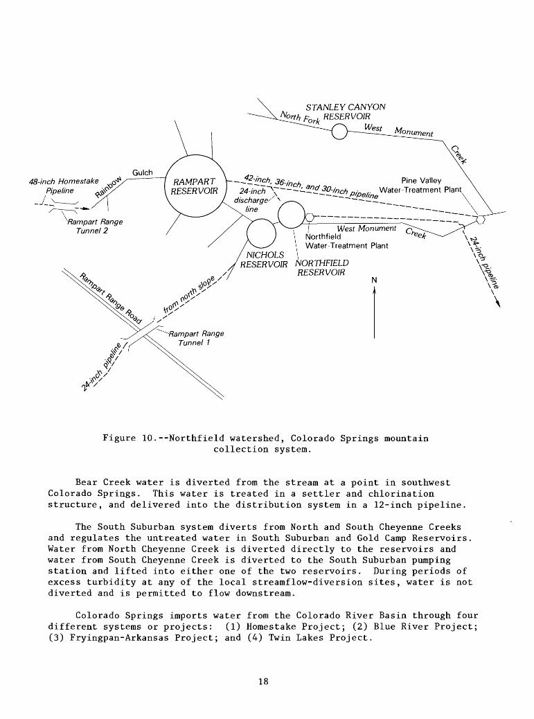
The Northfield watershed (fig. 10) is located on the Rampart Range northwest of Colorado Springs. The Northfield watershed produces only a minor proportion of Colorado Springs water supply locally, but the reservoirs are important for regulating water from other sources. The three Northfield reservoirs Rampart, Nichols, and Northfield--have a combined capacity of 41,748 acre-feet, 40,886 acre-feet of which is in Rampart Reservoir. Water from the 48-inch Homestake pipeline enters the Northfield watershed through Rampart Range tunnel 2, which discharges into Rainbow Gulch. Water conveyed by the Homestake pipeline usually is water from the upper Arkansas basin via Trout Creek which is Homestake, Fryingpan-Arkansas, or Twin Lakes Project water; but the capability exists to divert Blue River water into Rampart Reservoir at the divide pumping station. North Slope water enters the North- field system through a 24-inch pipeline in Rampart Range tunnel 1 and flows into Nichols Reservoir.
Water from Rampart Reservoir flows through a 42-, 36-, and 30-inch pipe line to the Pine Valley water-treatment plant. Water from this line can be diverted to the Northfield Reservoir. Water also can be released from Rampart Reservoir downstream to Nichols Reservoir. Water from Nichols Reservoir is discharged to Northfield Reservoir by channel flow. Northfield Reservoir supplies the Northfield water-treatment plant. (Stanley Canyon Reservoir, Reservoir No. 2, is no longer a part of the Colorado Springs system; it has been leased to the U.S. Air Force Academy.)
The Penrose-Rosemont watershed (fig. 11) is located southwest of Colorado Springs on Gold Camp Road. Rosemont Reservoir, with a capacity of 2,538 acre-feet, is located on East Beaver Creek. Water also is diverted from Gould Creek to a 20-inch pipeline inside Rogers Tunnel. From Rosemont Reservoir, water is transported through a 10-inch pipeline to Fisher Canyon and Penrose Reservoirs, or to the Broadmoor water-treatment plant.
About 5 percent of the water consumed annually by Colorado Springs comes from local streams, including Fountain Creek, Bear Creek, North and South Cheyenne Creeks, and Sutherland Creek (fig. 12). Water is pumped from Foun tain Creek at the 33rd Street pumping station. Four pumps in this station boost the water through a 20-inch pipeline to the Mesa water-treatment plant, about \\ miles to the northeast. Water from Sutherland Creek no longer is diverted directly from that creek but now is diverted from Fountain Creek at the 33rd Street pumping station.
17
48-inch Homestake Pipeline
"Rampart Range Tunnel 2
STANLEY CANYON RESERVOIR
RAMPART 4*~nch, 36-i ~ Water-Treatment Plant~~^inch pi.
discharge/ x line
West Monument NorthfieldWater-Treatment Plant
NICHOLSRESERVOIR NORTHFIELD
RESERVOIRN
A*\&
& /
0(
«sf?'
-Rampart Range Tunnel 7
\
Figure 10.--Northfield watershed, Colorado Springs mountaincollection system.
Bear Creek water is diverted from the stream at a point in southwest Colorado Springs. This water is treated in a settler and chlorination structure, and delivered into the distribution system in a 12-inch pipeline.
The South Suburban system diverts from North and South Cheyenne Creeks and regulates the untreated water in South Suburban and Gold Camp Reservoirs. Water from North Cheyenne Creek is diverted directly to the reservoirs and water from South Cheyenne Creek is diverted to the South Suburban pumping station and lifted into either one of the two reservoirs. During periods of excess turbidity at any of the local streamflow-diversion sites, water is not diverted and is permitted to flow downstream.
Colorado Springs imports water from the Colorado River Basin through four different systems or projects: (1) Homestake Project; (2) Blue River Project; (3) Fryingpan-Arkansas Project; and (4) Twin Lakes Project.
18

ROSEMONT RESERVOIR
10-inch pipeline to Fisher Canyon Reservoir, Penrose Reservoir, or Broadmoor Water-Treatment Plant
Figure 11.--Penrose-Rosemont watershed, Colorado Springs mountain collection system.
The Homestake and Blue River Projects are significant only to the Colo rado Springs system in the Arkansas River basin, but the Fryingpan-Arkansas Project and the Twin Lakes Project are significant in other parts of the Arkansas River basin. For this reason, the latter two projects are discussed separately elsewhere in this report.
The collection system of the Homestake Project intercepts the headwaters of the Eagle River about 160 miles west of Colorado Springs (fig. 13). The project is a joint venture of the cities of Colorado Springs and Aurora. Colorado Springs average share of the yearly diversion is 12,900 acre-feet. Water is diverted from Fancy Creek, French Creek, Sopris Creek, Missouri Creek, Homestake Creek, and East Fork Homestake Creek. Phase II of this project would extend the collection system to intercept Whitney Creek, Fall Creek, Cross Creek, and East and West Forks Cross Creek. The water is collected in Homestake Reservoir (capacity 43,300 acre-feet), and then moved through the Continental Divide in the Homestake Tunnel. Homestake Tunnel discharges into Lake Fork Arkansas River, which in turn flows into Turquoise Lake (Sugarloaf Reservoir).
19

to Mesa Water-Treatment Plant
33rd Street Pumping System
12-inch pipelineto distribution
system
Bear Creek Intake Settler and Chlorination Sturcture
SOUTH SUBURBAN12-inch pipeline
GOLD CAMP ^-^ , RESERVOIR f \\
Jo-inch pipeline
20-inch pipeline^' North Cheyenne Creek
South Suburban Pumping Station
Myers Ditch Intake
12-inch pipeline
Figure 12.--Local streamflow diversions, Colorado Springs system,
20

Tennessee Pass
HOMES TAKE RESERVOIR
TURQUOISE LAKE (SUGARLOAF RESERVOIR)
FRYINGPAN-ARKANSAS PROJECT
LEADVILLE
to Twin Lakes to Otero Pumping Plant
Figure 13.--Homestake Project collection system.
21
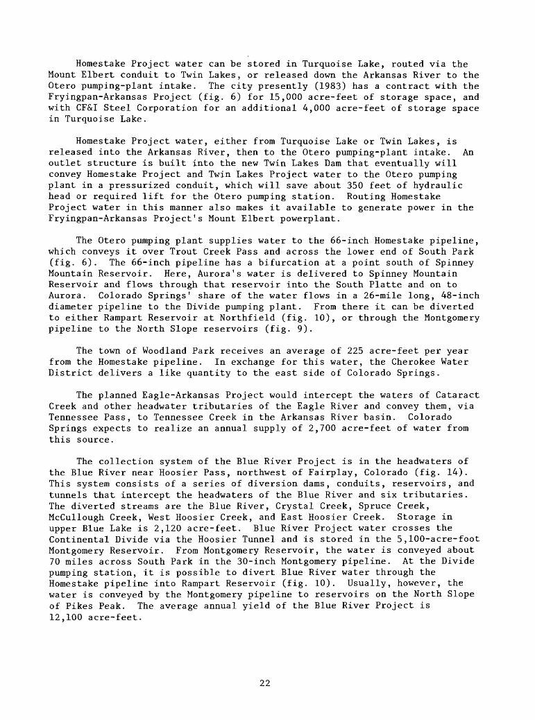
Homestake Project water can be stored in Turquoise Lake, routed via the Mount Elbert conduit to Twin Lakes, or released down the Arkansas River to the Otero pumping-plant intake. The city presently (1983) has a contract with the Fryingpan-Arkansas Project (fig. 6) for 15,000 acre-feet of storage space, and with CF&I Steel Corporation for an additional 4,000 acre-feet of storage space in Turquoise Lake.
Homestake Project water, either from Turquoise Lake or Twin Lakes, is released into the Arkansas River, then to the Otero pumping-plant intake. An outlet structure is built into the new Twin Lakes Dam that eventually will convey Homestake Project and Twin Lakes Project water to the Otero pumping plant in a pressurized conduit, which will save about 350 feet of hydraulic head or required lift for the Otero pumping station. Routing Homestake Project water in this manner also makes it available to generate power in the Fryingpan-Arkansas Project's Mount Elbert powerplant.
The Otero pumping plant supplies water to the 66-inch Homestake pipeline, which conveys it over Trout Creek Pass and across the lower end of South Park (fig. 6). The 66-inch pipeline has a bifurcation at a point south of Spinney Mountain Reservoir. Here, Aurora's water is delivered to Spinney Mountain Reservoir and flows through that reservoir into the South Platte and on to Aurora. Colorado Springs' share of the water flows in a 26-mile long, 48-inch diameter pipeline to the Divide pumping plant. From there it can be diverted to either Rampart Reservoir at Northfield (fig. 10), or through the Montgomery pipeline to the North Slope reservoirs (fig. 9).
The town of Woodland Park receives an average of 225 acre-feet per year from the Homestake pipeline. In exchange for this water, the Cherokee Water District delivers a like quantity to the east side of Colorado Springs.
The planned Eagle-Arkansas Project would intercept the waters of Cataract Creek and other headwater tributaries of the Eagle River and convey them, via Tennessee Pass, to Tennessee Creek in the Arkansas River basin. Colorado Springs expects to realize an annual supply of 2,700 acre-feet of water from this source.
The collection system of the Blue River Project is in the headwaters of the Blue River near Hoosier Pass, northwest of Fairplay, Colorado (fig. 14). This system consists of a series of diversion dams, conduits, reservoirs, and tunnels that intercept the headwaters of the Blue River and six tributaries. The diverted streams are the Blue River, Crystal Creek, Spruce Creek, McCullough Creek, West Hoosier Creek, and East Hoosier Creek. Storage in upper Blue Lake is 2,120 acre-feet. Blue River Project water crosses the Continental Divide via the Hoosier Tunnel and is stored in the 5,100-acre-foot Montgomery Reservoir. From Montgomery Reservoir, the water is conveyed about 70 miles across South Park in the 30-inch Montgomery pipeline. At the Divide pumping station, it is possible to divert Blue River water through the Homestake pipeline into Rampart Reservoir (fig. 10). Usually, however, the water is conveyed by the Montgomery pipeline to reservoirs on the North Slope of Pikes Peak. The average annual yield of the Blue River Project is 12,100 acre-feet.
22

MONTGOMERY RESERVOIR
Fairplay
Figure 14.--Blue River Project collection system,
23

The Fryingpan-Arkansas Project is a multipurpose U.S. Bureau of Reclama tion Project described in detail later in this report. Colorado Springs, with the nearby communities of Fountain, Security, Widefield, and Stratmoor Hills, are participants in the project and will receive water from that source. Colorado Springs eventually expects to receive 14,400 acre-feet of water from the project. Delivery will be through the Fountain Valley pipeline, now (1983) under construction, from Pueblo Reservoir to the south side of Colorado Springs. Until construction of the Fountain Valley pipeline is complete, deliveries of Fryingpan-Arkansas Project water are being made through the Otero pumping station and Homestake pipeline.
In recent years, Colorado Springs has participated in the winter- water-storage program, an outgrowth of the Fryingpan-Arkansas Project operations. In 1981, 1982, and 1983, participation has been by storage in Twin Lakes Reservoir, with simultaneous release of return flow from imported water down Fountain Creek. When the winter-water-storage program is in operation, Colorado Springs stores in its reservoir inflow in addition to that allowed by priority.
The Twin Lakes Project also is described later in this report. Colorado Springs owns 49.845 percent of outstanding shares of Twin Lakes Project water; future total supply from the source is expected to be 27,000 acre-feet annually. In addition to water yielded by the project, the city also has the right to use storage in Twin Lakes Reservoir. Twin Lakes Reservoir is on Lake Creek, which has its confluence with the Arkansas River about 5 miles upstream from the intake to the Otero pumping station. Twin Lake Project water is brought into the Colorado Springs system through the Homestake pipeline.
Ground water provides a small (generally about 3 percent) but important segment of Colorado Springs water supply. Ground-water sources are the Pinello Ranch, the Hanna Ranch, and the wells of the Cherokee Water District. The city's contract with the Venetucci Ranch (which is located just west of Security) expired.
The Cherokee Water District supplies about 225 acre-feet of water annually from their well field in the Black Squirrel Creek basin east of the city. This water is purchased from the Cherokee Water District by Woodland Park, and exchanged for a like quantity of water, delivered via the Homestake pipeline.
The Pinello Ranch is located on the flood plain of Fountain Creek immediately west of the town of Security. Fourteen wells produce from the Widefield aquifer. Water from these wells is routed through a pumping, chlorination, and metering station by a 16-inch pipeline, into the distri bution system serving Security and Colorado Springs; the wells also are used for domestic purposes and irrigation on the ranch. Ground-water recharge from six ponds on the Pinello Ranch is supplied by the Stubbs and Miller Ditch; wells are an alternate point of diversion for that ditch. A discharge of 2.45 cubic feet per second is allowed annually from the wells; total yield to the system from the Pinello Ranch wells is 1,400 acre-feet per year.
24
The Hanna Ranch was purchased when the city acquired the Pinello Ranch, on January 1, 1973. Located about 4 miles south of Fountain, the Hanna Ranch is the site of the new R.D. Nixon powerplant. Water rights for the Owen and Hall ditch acquired with the ranch are used, in part, in a plan of augmenta tion for 14 wells on the ranch. Water from the wells supply the town of Fountain, and Unit 1 of the R.D. Nixon powerplant. An average of 4,700 acre- feet per year is supplied to the powerplant from this source.
The Supreme Court of Colorado determined that Colorado water law allows municipalities "...to reuse, make successive uses, and after use to have the right of deposition of imported water..." (Radosevich and others, 1975). In recent years, Colorado Springs used an average of 6,200 acre-feet of imported return flow. Reuse of imported water is for nonpotable purposes, such as irrigation of golf courses, parks, parkways, for cleaning streets, and it may be used for cooling water to powerplants. Transmountain-return flow also is used to offset ground-water depletions at the Pinello and Hanna Ranches, to offset storage and excess diversions from the Pikes Peak watershed, South Suburban storage, and Fort Carson water reuse. For this purpose, a strict accounting of transmountain-return flow and reuse is made by Colorado Springs to the Water Commissioner (Irrigation Division No. 2, Water District 10).
City of Pueblo
The city of Pueblo obtains its water through the Pueblo Board of Water Works; a public, revenue-supported water utility. The city's raw-water supply is from three sources: (1) Direct-flow rights; (2) storage rights; and (3) transmountain diversions. The existing treatment plant is designed to process from 53 million gallons per day (82.0 cubic feet per second) to a maximum of 80 million gallons per day (123.8 cubic feet per second). At Pueblo's present size, direct flow rights satisfy municipal demand most of the year. Critical periods occur early in the spring, before snowmelt runoff begins, and in the fall, when the river is low. During these times, streamflow is supplemented with reservoir water.
The Pueblo Board of Water Works operates Clear Creek Reservoir on Clear Creek in Chaffee County (fig. 15). The storage rights for Clear Creek Reservoir include 11,439 acre-feet from the waters of Clear Creek; the reservoir also stores the Board's transmountain diversions by exchange.
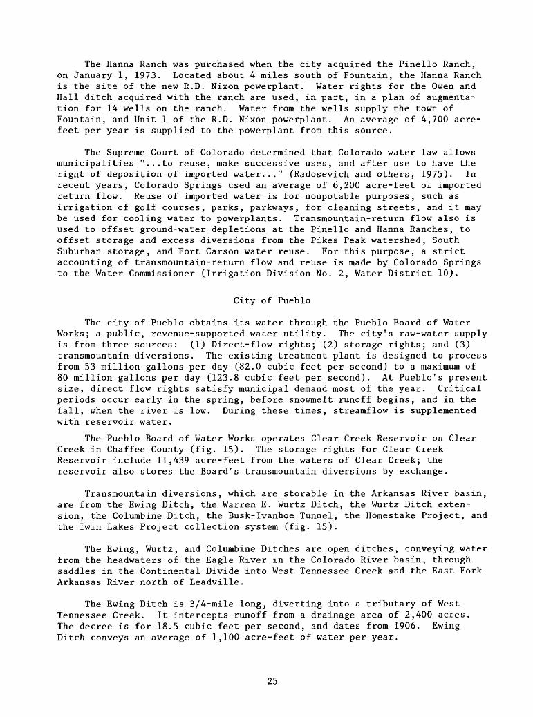
Transmountain diversions, which are storable in the Arkansas River basin, are from the Ewing Ditch, the Warren E. Wurtz Ditch, the Wurtz Ditch exten sion, the Columbine Ditch, the Busk-Ivanhoe Tunnel, the Homestake Project, and the Twin Lakes Project collection system (fig. 15).
The Ewing, Wurtz, and Columbine Ditches are open ditches, conveying water from the headwaters of the Eagle River in the Colorado River basin, through saddles in the Continental Divide into West Tennessee Creek and the East Fork Arkansas River north of Leadville.
The Ewing Ditch is 3/4-mile long, diverting into a tributary of West Tennessee Creek. It intercepts runoff from a drainage area of 2,400 acres. The decree is for 18.5 cubic feet per second, and dates from 1906. Ewing Ditch conveys an average of 1,100 acre-feet of water per year.
25

Warren E. Wurtz Ditch and Extension Ewing Ditch Columbine Ditch
Homestake Tunned
Charles H. Boustead^ Tunnel
Car/ton (Busk-lvanhoe) Tunnel
TURQUOISE'%^ LAKE
Mt Elbert Forebay
Mount Elbert Powerplant-
TWIN LAKES RESERVOIR
Independence Pass (Twin Lakes) Tunnel
LAKE COUNTY
CHAFFEE COUNTY
CLEAR CREEK RESERVOIR
Clear Creek
/Homestake \ Pipeline\ \ \
Otero \_^Pumping Station
X
to Trout Creek Pass
Buena Vista
Figure 15.--Pueblo Board of Water Works system and other water develop ment in upper Arkansas River basin, upstream from Buena Vista.
26

The Wurtz Ditch is 5 miles long and the Wurtz Ditch extension is another 6 miles long. The ditch and the extension together intercept runoff from a drainage area of 5,840 acres. The decree for Wurtz Ditch is dated 1929, and is for 85 cubic feet per second; the Wurtz Ditch extension decree is dated 1953, and is for 100 cubic feet per second. The Wurtz Ditch empties into West Tennessee Creek. During the past decade, the Wurtz Ditch has conveyed an average of 3,000 acre-feet per year.
The Columbine Ditch intercepts runoff from a drainage area of 1,170 acres in the headwaters of the Eagle River basin and empties into Chalk Creek, a tributary of the East Fork Arkansas River. The Columbine Ditch has a 1930 decree for 60 cubic feet per second. Recent diversions through the Columbine Ditch have been about 1,700 acre-feet per year.
The Busk-Ivanhoe system is owned jointly by the Pueblo Board of Water Works and the Highline Canal Company. Water is diverted from Ivanhoe Creek, a tributary of the Fryingpan River in the Roaring Fork basin to Busk Creek, a Lake Fork tributary, via Carlton (Busk-Ivanhoe) Tunnel. Fryingpan-Arkansas Project's Charles H. Boustead Tunnel also can be used during low-demand periods. The Board realizes an average annual yield of 3,100 acre-feet from the Busk-Ivanhoe system.
The Board is entitled annually and in perpetuity a total of 2,500 acre- feet of Homestake Project water. The Board also has other rights, now held in reserve for future municipal expansion. Waters from these reserve rights con tinue to be used for the same agricultural purposes that existed prior to acquisition by the Board. These rights include a part of the water from West Pueblo Ditch, the Leadville Ranch (a potential reservoir site, plus a direct- flow right), and shares of the Twin Lakes Project. The Board also controls 11,476.16 shares of Twin Lakes Project water with a potential yield of 12,624 acre-feet. The Board decides yearly if the water is needed for muni cipal purposes; otherwise, this water goes to agricultural land supplied by the Colorado Canal Company, that originally owned controlling interests in the Independence Pass (Twin Lakes) Tunnel diversion.
City of Trinidad
The city of Trinidad obtains its water supply from a collection system located in the mountains about 30 miles west of the city. The collection system consists of two reservoirs, ditches supplying these reservoirs, pipe lines from the reservoirs to a filtration plant, and a pipeline from the filtration plant to the city (fig. 16). During 1982, 5,100 acre-feet were supplied to Trinidad water customers.
North Lake, with a decreed capacity of 4,315 acre-feet, receives most of its inflow from North Fork Purgatoire River, through the North Lake inlet, and discharges to the Trinidad filtration plant through the North Lake pipeline. Monument Lake, with a decreed capacity of 1,430 acre-feet, receives water from several sources. Monument Lake ditch No. 1 diverts from North Fork Purgatoire River into the channel of Brown Creek. Downstream from where Monument Lake ditch No. 1 enters, Monument Lake ditch No. 2 diverts from Brown Creek into Monument Lake. The Cherry Creek ditch diverts from Cherry Creek and is joined
27

NORTH LAKE
MonumentDitch No 1
Monument Ditch No 2
&*,
fr,.<** r\vVn
J^
LAKE
c.
u*
Monument^ Lake Inlet
Cherry Creek -J. Ditch
ce<^
&*o
\M ,̂^
.a
>/>e
"^-^,
ike Pipeline ^^
% \\r-\^r\^\\-s.
\-o\%r.\^
\^ W^^~^_ ^ ̂
Trinidad Filtration Plant
to Weston, Sequndo, Cokedale, Valdez, and Trinidad
Figure 16.--City of Trinidad mountain collection system.
with the "C" ditch, which diverts from Whiskey Creek to form the Monument Lake inlet that discharges into Monument Lake. Water is conveyed from Monument Lake to the filtration plant in the Monument Lake pipeline.
Usually, only North Lake is used to supply the filtration plant; Monument Lake is held as an emergency reserve. A relative balance of inflow and demand enables North Lake to be maintained with only minor fluctuation of content throughout most of the year.
Trinidad has an option for as much as 7,100 acre-feet per year of Trini dad Dam and Reservoir Project water. To exercise this option would require court action to change from present agricultural use to municipal use; this option is being held in reserve to supply future municipal expansion.
28

City of Walsenburg
The city of Walsenburg obtains its municipal water supply from the Cucharas River and Wahatoya Creek. The 16-inch Walsenburg pipeline diverts water into Wahatoya Lake from the Cucharas River just upstream from the town of La Veta. The Francisco and Daigre (Mill) ditch diverts water into Wahatoya Lake from both the Cucharas River and Wahatoya Creek. Overflow from Wahatoya Lake, 274 acre-feet capacity, is stored in Daigre Lake, 139 acre-feet (fig. 17). These lakes also are a part of the Wahatoya Colorado State Wild life Area.
LATHROP STATE PARK
LAKE MIRIAM (HORSESHOE LAKE)
LAKE OEHM (MARTIN LAKE)
Pump
WALSENBURG RESERVOIR12-inch pipeline
(standby)
Filtration plant
Two 12-inch pipelines
\WAHATOYA/XWAHATOYA STATE WILDLIFE AREA
Figure 17.--City of Walsenburg municipal water-supply system.
29
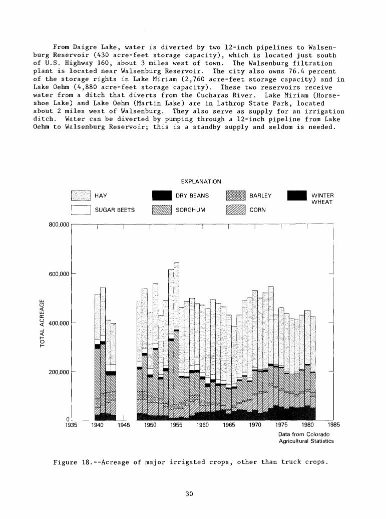
From Daigre Lake, water is diverted by two 12-inch pipelines to Walsen- burg Reservoir (430 acre-feet storage capacity), which is located just south of U.S. Highway 160, about 3 miles west of town. The Walsenburg filtration plant is located near Walsenburg Reservoir. The city also owns 76.4 percent of the storage rights in Lake Miriam (2,760 acre-feet storage capacity) and in Lake Oehm (4,880 acre-feet storage capacity). These two reservoirs receive water from a ditch that diverts from the Cucharas River. Lake Miriam (Horse shoe Lake) and Lake Oehm (Martin Lake) are in Lathrop State Park, located about 2 miles west of Walsenburg. They also serve as supply for an irrigation ditch. Water can be diverted by pumping through a 12-inch pipeline from Lake Oehm to Walsenburg Reservoir; this is a standby supply and seldom is needed.
HAY
SUGAR BEETS
EXPLANATION
DRY BEANS
SORGHUM
WINTER WHEAT
800,000
01935 1940 1945 1950 1955 1960 1965 1970 1975 1980 1985
Data from Colorado Agricultural Statistics
Figure 18.--Acreage of major irrigated crops, other than truck crops.
30
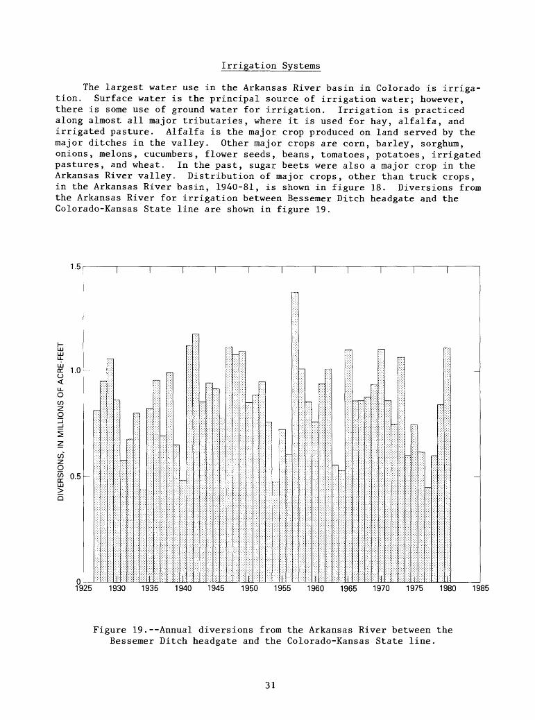
Irrigation Systems
The largest water use in the Arkansas River basin in Colorado is irriga tion. Surface water is the principal source of irrigation water; however, there is some use of ground water for irrigation. Irrigation is practiced along almost all major tributaries, where it is used for hay, alfalfa, and irrigated pasture. Alfalfa is the major crop produced on land served by the major ditches in the valley. Other major crops are corn, barley, sorghum, onions, melons, cucumbers, flower seeds, beans, tomatoes, potatoes, irrigated pastures, and wheat. In the past, sugar beets were also a major crop in the Arkansas River valley. Distribution of major crops, other than truck crops, in the Arkansas River basin, 1940-81, is shown in figure 18. Diversions from the Arkansas River for irrigation between Bessemer Ditch headgate and the Colorado-Kansas State line are shown in figure 19.
1.5
o <LL O
CO
1.0
COz o£UJ>Q
0.5
01925 1930 1935 1940 1945 1950 1955 1960 1965 1970 1975 1980 1985
Figure 19.--Annual diversions from the Arkansas River between the Bessemer Ditch headgate and the Colorado-Kansas State line.
31

Through the years, the area of land irrigated in the Arkansas Valley has remained relatively stable at about 415,000 acres (U.S. Bureau of Reclamation, 1969), but the seasonal water supply to this area is subject to considerable fluctuations. Waters of the Arkansas River and its tributaries, and water imported into the basin, are used and reused throughout the area.
Storage reservoirs are used throughout the basin. In the upstream reaches of the Arkansas River, and on all of its tributaries, the general practice is for the storage rights and the junior direct-flow rights to store or irrigate very early in the season, later to be called out by senior rights. The river call on the tributaries usually is much senior to the call on the main stem during irrigation seasons of average or low flow.
Arkansas River
The major irrigation systems along the Arkansas River will be described in this section. The Arkansas River is in Water Districts 11, 12, 14, 17, and 67 (pi. 1). A schematic diagram of the major irrigation systems along the river is given on plate 3 (in the pocket), and the major water rights are listed in plate 4 (in the pocket). The active ditches and major ditches on the Arkansas River tributaries are listed in table 5 in the Supplemental Data section at the end of the report.
Water from most of the ditches in Water District 11 (Lake and Chaffee Counties) and Water District 12, upstream from the Royal Gorge, is used to irrigate alfalfa, hay, or irrigated pasture. In the Canon City area, the South Canon Ditch diverts water from the south bank just upstream from Grape Creek. This ditch, which splits within the limits of Canon City and becomes the Pump Ditch and the Crooked Ditch, irrigates about 1,280 acres in and near the south side of Canon City. The Canon City Hydraulic Ditch diverts from the north bank just upstream from the streamflow-gaging station 07096000 Arkansas River at Canon City, flows through the grounds of the Colorado State Peniten tiary, and on through Canon City. The Fruitland Ditch is supplied from the Canon City Hydraulic Ditch via a buried conduit within Canon City. The Grandview Ditch diverts from the Canon City Hydraulic Ditch at a point just before that ditch wastes into Fourmile Creek near the east edge of town. The Grandview Ditch crosses under U.S. Highway 50 and Fourmile Creek in a buried conduit, and irrigates lands on the State prison farm. In the past, the Fruitland Ditch was diverted, along with Canon City's municipal water, in another ditch, the Canon City Aqueduct. Canon City has abandoned that aque duct, and now diverts from a new diversion dam in the river, about 3 miles downstream from the old diversion point.
The Canon City and Oil Creek (Mill) Ditch diverts from the north bank just downstream from the Canon City's diversion dam and irrigates about 1,250 acres near the east edge of town. This ditch also receives discharge from the Southern Colorado Power Company's powerplant; the outflow is charged against the Canon City and Oil Creek Ditch's water right.
The Fremont County Ditch diverts from the right bank, midway between Canon City and Florence, irrigating about 425 acres of flood plain. The Union Canal is diverted with the Minnequa Canal and is bifurcated from that canal on
32
the west edge of Florence, irrigating about 1,250 acres of land in and east of that town. The Hannenkratt ditch, which diverts from the north bank, irri gates Colorado State Penitentiary land on the flood plain across the river from Florence. The Lester and Atteberry ditch, which diverts from the north bank, irrigates about 180 acres of flood plain east of Florence. Irrigation in the Canon City area serves orchards, some truck crops, and alfalfa.
Major irrigation conveyances diverting from the Arkansas River in Water District 14 are the Bessemer Ditch, Colorado Canal, Highline Canal, and Oxford Farmers Ditch. Smaller irrigation ditches are Hamp-Bell, West Pueblo, River side Dairy, Excelsior, and Collier Ditches. The Bessemer Ditch is diverted through a special outlet in Pueblo Dam. It flows in an open canal through the south side of the city of Pueblo, and through the CF&I Steel Corporation mill partially in a closed conduit, irrigating about 20,000 acres on the St. Charles mesa, southeast of Pueblo. When the ditch is diverting, it also delivers water to the St. Charles Mesa Water District, a municipal user. The Colorado Canal diverts from the north bank about 3% miles upstream from the confluence of the Huerfano River, irrigating about 50,800 acres in Pueblo and Crowley Counties. The Colorado Canal once had exclusive control over the Twin Lakes Reservoir and transmountain diversion system (discussed elsewhere in this report). Irrigators using the canal have sold most of their rights to the transmountain diversion and the storage space in Twin Lakes that formerly regulated those imports to outside interests. The Colorado Canal has two major off-stream storage reservoirs: Lake Henry and Lake Meredith (also known as Bob Creek Reservoir). Water is stored in these reservoirs during the winter. From Lake Henry, the lands irrigated by the Colorado Canal can be irrigated directly by gravity flow. Lake Meredith is topographically too low to irrigate lands by gravity flow. An exchange with the Holbrook Canal, the Fort Lyon Storage Canal, or the Arkansas River is necessary to enable use of Lake Meredith water by users of the Colorado Canal. The Lake Meredith outlet (pi. 3) crosses both canals, before discharging into the river; depending on which canal is in priority at the time, the exchange is made by releasing water through the outlet into the receiving channel, and diverting a like quantity at the Colorado Canal headgate. To accomplish this exchange, suffi cient water must be left in the river at the Colorado headgate to satisfy all senior rights downstream between the headgate and either the outlet canal or the headgate of the canal with which the exchange is being made. Water can be delivered from Lake Henry into Lake Meredith.
The Highline Canal Company has rights to divert not only native water from the Arkansas River, but also is part owner with the Pueblo Board of Water Works, of the Busk-Ivanhoe transmountain diversion. Highline Canal Company has a contract with the Fryingpan-Arkansas Project to store imported water in that project's Turquoise Lake. Transmountain water is used to supplement direct diversions, and to maintain an even-flowing ditch during irrigation season. The Highline Canal diverts from the south bank at a point just down stream from the Huerfano River, irrigating 26,000 acres in Pueblo and Otero Counties.
The Oxford Farmers Ditch diverts from the south side of the river at a point about 5 miles downstream from the mouth of the Huerfano River, irrigat ing about 6,000 acres of land in Pueblo and Otero County.
33

The Otero, Catlin, Holbrook, Fort Lyon Storage, Rocky Ford, Fort Lyon, and Las Animas Consolidated Canals headgates are all in Water District 17. The Otero Canal diverts from the south side of the river at a point about 6 miles upstream from the mouth of the Apishapa River. This canal is siphoned under the Apishapa River and irrigates about 10,000 acres in Otero County.
The Catlin Canal diverts from the south side of the river just downstream from the confluence of the Apishapa River, irrigating about 18,800 acres on the south side of the Apishapa River near Manzanola and Rocky Ford. The Catlin Canal Company owns the Larkspur transmountain diversion, and part of Wright's or Mount Pisgah Reservoir on Fourmile or Oil Creek. The Catlin Canal Company usually stores its transmountain diversions by exchange in space, leased in the Fryingpan-Arkansas Project system.
Holbrook Canal diverts from the north bank a short distance downstream from the State Highway 207 bridge near Manzanola. Exchange water from Lake Meredith can be released into Holbrook Canal. From the Holbrook Canal, water can be stored in the 7,986-acre-foot Dye Reservoir, or the 7,472-acre-foot Holbrook Reservoir. Neither reservoir normally can release water directly to the land, but must rely on an exchange with the river. The Rocky Ford Ditch is the main water right considered in this exchange. The Holbrook Canal irri gates 19,550 acres of land, and wastewater flows into Horse Creek. Cheraw Lake is filled by seepage and local drainage, and is not used to irrigate lands.
The Rocky Ford Canal diverts from the south bank at a point about midway between the towns of Manzanola and Rocky Ford. Water rights in this canal are very early water rights and are in priority most of the time. This canal maintains an even flow by using a self-adjusting wasteway gate, just upstream from the measuring section, which is located about 1 mile downditch from the headgage, and some water is diverted around the Fort Lyon Storage Canal diver sion dam in this manner. The Rocky Ford Canal irrigates about 8,200 acres, in and near the town of Rocky Ford; until recently, a part of the diversions of the Rocky Ford Canal was industrial water for a now-defunct sugar factory.
The Fort Lyon Storage Canal headgate is located about 1 mile downstream from the Holbrook Canal headgate. The Fort Lyon Storage Canal delivers water to Horse Creek Reservoir and to Adobe Creek Reservoir. Horse Creek Reservoir, 28,000 acre-feet, also has a storage right to the waters of Horse Creek, and can deliver irrigation water directly to the Fort Lyon Canal. Adobe Creek Reservoir, 85,000 acre-feet, also has a storage right to waters from Adobe Creek. Releases from Adobe Creek Reservoir go down the channel of Adobe Creek directly into the Fort Lyon Canal. The Fort Lyon Storage Canal can receive exchange water from the Lake Meredith Outlet Canal.
The Fort Lyon Canal diverts from the north side of the river about midway between Swink and La Junta. It can receive water from Horse Creek and Adobe Creek Reservoirs, as well as from the creeks for which those reservoirs were named. Downcanal from Adobe Creek, water can be delivered to the Kicking Bird Canal for storage in the Great Plains Reservoir system (discussed later under the Amity Canal).
34

Tailwater from the Fort Lyon Canal either can flow directly into the 2,500-acre-foot Thurston Reservoir, or can collect in an unnamed reservoir at the end of the canal. From Thurston Reservoir, an exchange is possible with the Amity Canal, through the West May Valley Drainage Ditch. The Fort Lyons Canal is divided into five divisions; each division receives irrigation water in turn. The Fort Lyon Canal receives a share of the Amity Canal's Great Plains water, as part of the arrangement whereby the Fort Lyon Canal is used to deliver water to the Kicking Bird Canal. Water from the Fort Lyon Canal irrigates about 91,300 acres in Crowley, Bent, and Prowers Counties.
The Las Animas Consolidated Canal diverts from the south side of the river, about 8 miles upstream from Las Animas. The Las Animas Consolidated Canal becomes the Las Animas Consolidated Extension, a ditch on the east side of the Purgatoire River. Water can be delivered from the Highland Ditch, which diverts from the Purgatoire River upstream from Las Animas into the Las Animas Consolidated Canal. The combined acreage irrigated by this system is about 6,950 acres, with 2,300 of these acres irrigated by the Las Animas Con solidated Extension. The headgate of the Las Animas Town Ditch was 4 miles downstream from the Consolidated Canal before the 1965 flood; water rights were transferred to Las Animas Consolidated Canal in March 1966. In April 1972, the Las Animas Town Ditch water rights were acquired by the Highline Canal, and were transferred to the Highline Canal headgate.
All of the canal and ditch systems on the Arkansas River downstream from John Martin Reservoir are in Water District 67; all these systems participate in the Arkansas River Compact. These systems, and systems in Kansas, store winter and excess streamflows in John Martin Reservoir for later use.
The Fort Bent Canal and the Keese ditch share a common diversion dam on the south bank about k\ miles downstream from John Martin Dam. The Keese ditch diverts out of the Fort Bent Canal, just downcanal from the headgate, irrigating the flood plain west of Lamar. The Fort Bent Canal flows through the city of Lamar, and irrigates lands both west and east of town. Water also is conveyed in the Fort Bent Canal to recharge the city of Lamar 1 s well field in Clay Creek. The combined area irrigated by the Fort Bent Canal and the Keese ditch is 8,740 acres.
The Amity Canal diverts from the north bank about 8 miles downstream from John Martin Dam and irrigates about 37,800 acres. The Great Plains Reservoirs [the Nee So Pah (Black Water), the Nee No She (Standing Water), the Nee Gronda (Big Water), and the Nee Skah (Queens) Reservoirs] are a part of the Amity system. They have a total capacity of 265,552 acre-feet and are connected to the Amity Canal by the Comanche Canal. These reservoirs are broad, shallow lakes, and the surface-area-to-capacity ratio allows significant evaporation. A large, dead-storage pool in the system permits considerably more stored water than can be withdrawn; therefore, storage for the Amity Canal is in John Martin Reservoir, instead of in the Great Plains Reservoirs whenever possible.
The Lamar Canal diverts from the south bank, just at the west edge of Lamar, irrigating about 8,700 acres east of town. The city of Lamar power- plant has a battery of wells for cooling water that discharges directly into the Lamar Canal, and this discharge is measured and charged to the Lamar Canal decree.
35

The Hyde ditch has recently changed its point of diversion from the headgate on the north bank just opposite the city of Lamar, to a point on the canal about 2 miles downditch from the old headgate. Water from the Arkansas River is pumped to the Hyde Canal at the new point of diversion, and the west ern part of the ditch is maintained to intercept the West May Valley Drainage Ditch. The Hyde ditch irrigates about 970 acres west of Big Sandy Creek.
The Manvel ditch irrigates about 750 acres on the south side of the river, from a headgate located about 7 miles downstream from Lamar. The Manvel ditch has been unable to divert through its headgate under normal conditions since the 1965 flood. The canal operates from wells, some seepage, and Arkansas River Compact storage water. Storage water is delivered through the Lamar Canal.
The X-Y Canal and Graham Ditch share a common ditch and headgate, about 4 miles downstream from the Manvel ditch headgate, irrigating about 6,000 acres on the south side of the Arkansas River. In recent years, the Graham water right has been transferred to the exclusive use of wells.
The Buffalo Canal diverts from the north bank, irrigating about 5,000 acres of land around Holly. The Buffalo Canal also has rights to divert out of Buffalo Creek. The Holly Drain drains land irrigated by the Buffalo Canal. The Sisson Ditch no longer irrigates with surface water; all rights of this ditch have been transferred to wells. The Frontier ditch, although its headgate is located in Colorado, irrigates land in Kansas, and is considered a Kansas ditch.
Arkansas River Tributaries
The raising of stock feed is the major use of irrigation on the Arkansas River basin tributaries. Alfalfa is perhaps the most common crop, followed by irrigated pasture, hay, and small grains. Surface water is the largest source of irrigation supply; but, with the advent of center-pivot sprinklers, some ground water is beginning to be used for irrigation.
Wet Mountain ValleyThe Wet Mountain Valley, located in Custer and Fremont Counties between
the Wet Mountains and the Sangre de Cristo Range, is drained by Grape and Texas Creeks. The drainage basins of those creeks comprise Colorado Water District 13.
Lake DeWeese (DeWeese-Dye Reservoir) is located on Grape Creek at the downstream end of the irrigated area. It regulates the irrigation supply of the DeWeese-Dye ditch, which diverts from the east bank of Grape Creek near the mouth, and irrigates orchard, truck crops, and alfalfa in and near Canon City.
Fourmile, Hardscrabble, and Beaver CreeksThe Canon Heights Irrigation Company uses five small reservoirs located
on the north side of Canon City that receive water from Fourmile Creek through the Park Center Ditch. Canon Heights Irrigation Company also controls one- seventh of Mount Pisgah Reservoir storage, with rights to the use of water from a nontributary flowing well. The Hardscrabble ditch on Hardscrabble Creek is the oldest water right in Water District 12, dating from May 1, 1860.
36

The Beaver Park Irrigation Company irrigates land around Penrose with water from Brush Hollow Reservoir, and with direct flow from Beaver Creek. Brush Hollow Reservoir, 4,125 acre-feet, stores water from Brush Hollow Creek, and is supplied from Beaver Creek through the Brush Hollow Supply Ditch and conduit. The Beaver Park Irrigation Company has recently acquired the right for storage in the top 2 feet of Skagway Reservoir. Skagway Reservoir, 3,678 acre-feet, was originally a hydroelectric power forebay; in recent years, it has been operated for recreation uses by the Colorado Department of Fish and Wildlife.
Fountain CreekFountain Creek is in Water District 10. Most irrigation systems divert
ing from Fountain Creek irrigate fields located on the flood plain of that creek, or the flood plain at the downstream end of major tributaries to Fountain Creek. Two larger systems serving terrace lands outside the flood plain in El Paso County are the Fountain Mutual ditch and the Chilicott Canal. The Fountain Mutual ditch diverts from the east bank, in the city of Colorado Springs, irrigating about 3,850 acres in and around the communities of Secu rity, Widefield, and Fountain. The Fountain Mutual ditch stores water in the 3,950-acre-foot Big Johnson Reservoir (Fountain Valley Reservoir 2). Little Johnson Reservoir (Fountain Valley Reservoir 3), 682 acre-feet, is no longer used to regulate Fountain Mutual irrigation water, but will be used as a re charge pond for ground-water recharge. Upstream from Big Johnson Reservoir, the Fountain Mutual ditch is known as Ditch 4; downditch from the reservoir, it is called the Fountain ditch.
The Chilicott Canal diverts from the east bank, about midway between the towns of Widefield and Fountain. The ditch is siphoned under Jimmy Camp Creek and irrigates about 3,000 acres. Irrigation supply is regulated in the 347-acre-foot Callahan Reservoir.
St. Charles RiverThe main tributary of the St. Charles River, Greenhorn Creek, is the
location of the earliest priority in the Arkansas River basin: the Hicklin ditch, with a water right from spring 1859. The St. Charles River basin comprises Water District 15. Reservoirs in the basin are for recreation and industrial purposes, although some incidental irrigation from some reservoirs is practiced.
Huerfano RiverThe Huerfano River basin is within three water districts: (1) The down
stream end, approximately that part in Pueblo County, is in Water District 14; (2) the upstream end is in Water District 79; and (3) the basin of the Cucharas River is in Water District 16. The Cucharas River basin is discussed in a subsequent part of the report. A transmountain diversion occurs at the headwaters of the Huerfano River. Medano Ditch conveys waters of Medano Creek in the San Luis Valley (Rio Grande basin) into Hudson Branch of South Muddy Creek in the Huerfano River basin. The Medano water imports are stored by exchange in Wolf, Roach, and Creager Reservoirs, and are used for irrigation on a large ranch. The flood plain of the Huerfano River, from Redwing east, is wide and irrigated. There is irrigation using the flows of the major trib utaries in the upstream end of the Huerfano Valley, especially Pass, Williams, and Turkey Creeks. Ditches with direct-flow rights, dating from June 1869 or
37
earlier, are usually in priority throughout the irrigation season; ditches with later priorities divert early in the season, and during high flow.
Orlando Reservoir, with storage rights totaling 4,350 acre-feet, receives water from the Orlando Ditch, which diverts water from the north bank about one-half mile upstream from Interstate Highway 25. Stored water can be released back into the Huerfano River and used on irrigated bottom lands. A broad area, located north of the Huerfano River and east of the Wet Mountains, is irrigated by the waters of Apache Creek. Clark Reservoir No. 1 receives water from a ditch, which diverts from the south bank of the Apache Creek just west of Interstate Highway 25.
The Huerfano Valley ditch diverts water to the 2,088 acre-foot Huerfano Valley Reservoir from which about 1,000 acres north of the river in Pueblo County is irrigated. The Huerfano Valley ditch receives the waters stored in Cucharas Reservoir.
The Farmers Nepesta ditch diverts from the east bank, about 15 miles upstream from the mouth of the Huerfano River. It irrigates about 350 acres and regulates water in the 2,500-acre-foot Dotson Reservoir, and in the Nepesta Reservoir No. 5.
The Welton Ditch irrigates about 1,500 acres south and east of the Huerfano River in Pueblo County. During most years, the Huerfano River is dry downstream from the Weldon Ditch headgate.
Cucharas RiverMajor tributaries of the Cucharas River that supply water for irrigation
are Middle Creek, Wahatoya Creek, Abeyta Creek, Bear Creek, and Santa Clara Creek. Reservoirs supplied from the Cucharas River (Water District 16) include municipal-supply reservoirs, such as the La Veta Town Reservoir, and the reservoirs of Wahatoya, Daigre, and Walsenburg (see fig. 17). Reservoirs, originally developed for irrigation supply, are today partially used for recreation, such as the 1,148 acre-foot Lake Miriam (Horseshoe Lake), and the 2,573-acre-foot Lake Oehm (Martin Lake), which are now in Lathrop State Park. Other irrigation reservoirs used primarily for recreation are the now-combined Maria and Stevens Reservoirs, east of Walsenburg, which are now a private game and fish reserve.
A number of reservoirs are still in use to regulate irrigation supply in the basin. The Sharps Orchard Reservoir (84 acre-feet of storage) and La Joya Reservoir (177 acre-feet of storage), receive water from the Cucharas River by the Gomez Ditch. The Holita Reservoir, 540 acre-feet, receives its supply from the Cucharas River through the Walsenburg ditch. The Arnold Flood Reservoir, 80 acre-feet, the Sunnyside Reservoir, 120 acre-feet, and the Saliba (Antonio D. Valdez) Reservoir, 4,858 acre-feet, are all supplied from Santa Clara Creek. Salas Reservoir, 14 acre-feet, in the Bear Creek basin is supplied by that creek. Cucharas Valley Reservoir, 40,960 acre-feet, is located on the channel of the Cucharas River at the downstream end of the basin. This reservoir stores irrigation water for the Huerfano Valley ditch, located downstream on the Huerfano River.
38

Apishapa RiverThe Apishapa River basin upstream from Tejana Arroyo forms Water Dis
trict 18. During most years, the Apishapa River is dry downstream from the Escondito ditch, which serves the Hidden Valley Ranch at the downstream end of the district. Just upstream from the Escondito ditch is the 4,766-acre-foot Seven Lakes Reservoir, the only reservoir in the district with a storage right. During the 1920's, a flood moved the channel of the Apishapa River away from the inlet of the Seven Lakes Reservoir and from the headgates of a number of ditches in the area. Many ditch owners have filed for new points of diversion and have re-established their rights; the Salisbury and Widderfield ditches, east of Aguilar, are examples of these re-established headgates.
Irrigators with water rights, dating from 1867 or earlier, are in priority throughout most of the irrigation season. Irrigators with junior rights obtain their water very early in the season, or during the occasional periods of greater-than-average flow.
Purgatoire RiverThe Purgatoire River basin is in Water Districts 17 and 19; the boundary
line between the districts is the Las Animas-Otero County line. In the upstream reaches of the basin, Russell Lake, 200 acre-feet, is used to regu late irrigation water; Monument and North Lakes are water-supply reservoirs for the city of Trinidad (described elsewhere in this report).
Upstream from Trinidad Lake, which is located 3 miles upstream from the city of Trinidad, most irrigation is for lands adjacent to the narrow flood plain of the Purgatoire River. The principal area of irrigation in the Purga toire River basin is located just east and downstream from Trinidad. Ditches in this area are part of the Purgatoire River Conservancy District and receive water from the Trinidad Project (described elsewhere in this report). Those ditches (fig. 20) are the Chilili Ditch, the Enlarged Southside ditch (which conveys water to the Victor Florez ditch), and the Lewelling-McCormick Ditch, all of which divert from the south bank of the Purgatoire River just down stream from Trinidad. Ditches in this area, diverting from the north side of the river, are the Baca-Joint ditch (also known as the Picketwire Ditch); the El Moro ditch; the Model Inlet Canal, from which water is diverted to the Johns Flood Canal; the Hoehne Ditch; and the Salas ditch. Upstream from the Salas ditch, the Burns and Duncan Ditch is supplied by pumping water from the Purgatoire River. Present operations of these canals are discussed in the section describing the Trinidad Dam and Reservoir Project elsewhere in this report.
Major tributaries downstream from the city of Trinidad, from which irri gation diversions are made, include Luning Arroyo, Chicosa Arroyo, Grey Creek, Frijole Creek, San Francisco Creek, San Ysidro Creek, and Trinchera Creek. A number of storage rights regulate irrigation supplies on the plains east of Trinidad. Some of the larger of these storage rights are the Hermosa Valley Reservoir, 1,000 acre-feet, supplied from San Francisco Creek; Brown Reservoir No. 1, 180 acre-feet, diverting from Van Bremer Arroyo, and Johns Reservoir, 395 acre-feet, supplied by the Baca-Joint (Picketwire) ditch. The storage right for the Model Reservoir, 20,000 acre-feet, has been transferred to Trinidad Reservoir. A new, very junior, storage right has been decreed at the site of Model Reservoir. The distribution system of the Model Outlet Canal
39

TRINIDAD RESERVOIR
MODEL
Burns and DuncanDitch
(River Canyon Ranch )
Figure 20.--Ditch systems in the irrigated area of the Trinidad Dam and Reservoir Project.
recently has been improved, and the water now is delivered to the field in underground pipes, allowing more efficient coverage with the existing water supply. Winter wheat is the principal crop being grown with water from the new system. Downstream from the area irrigated by the Trinidad Dam and Reser voir Project, the river enters the 65-mile Purgatoire Canyon.
Two major ditches divert from the river downstream from Purgatoire Canyon in Otero and Bent Counties: the Ninemile and the Highland Canals. Both irrigate lands on the west side of the river. Highland Canal water rights are senior to Ninemile Canal water rights; however, by a court decision, Ninemile Canal is not obligated to pass flows smaller than certain limits to the High land Canal. The limits below which the call is considered to be a futile call ranges from 3 cubic feet per second in the winter to 8 cubic feet per second in the summer.
40

Industrial System: CF&I Steel Corporation
The CF&I Steel Corporation (CF&I), formerly Colorado Fuel and Iron Corporation, is the largest industrial user of Arkansas River basin water in Colorado. CF&I annually diverts between 80,000 and 110,000 acre-feet (a continuous supply is required) for use in their Pueblo plant. Less than 20 percent of diverted water is consumed; the rest is returned to the river. Formerly, the major uses of the water by CF&I were steam production and cooling (Adkins, 1962). Currently (1983) power is purchased from an outside source, and cooling is the primary water use. To assure an adequate supply, CF&I acquired some of the earliest water rights in the basin, including direct-flow rights from the Arkansas and St. Charles Rivers, plus storage rights in the upper basin. CF&I also has water rights in the Purgatoire River basin for use in coal-mining operations.
CF&I's upstream storage right is 27,416 acre-feet in Turquoise Lake (behind Sugar Loaf Dam) near Leadville (a part of the U.S. Bureau of Reclama tion's Fryingpan-Arkansas Project) (fig. 15). Turquoise Lake is an enlarge ment of a 17,416-acre-foot reservoir formerly owned by CF&I; the corporation also held conditional decrees for a planned enlargement of the lake. As a condition of the acquisition of the site by the U.S. Bureau of Reclamation, CF&I retained 17,416 acre-feet of storage space in the enlarged reservoir, and an option, since exercised, to lease an additional 10,000 acre-feet. Water stored in this space is from water rights CF&I holds on Lake Fork, Tennessee Fork, and East Fork. Water from the last two streams are stored in Turquoise Reservoir by exchange.
Three regulating reservoirs, with a combined storage of about 12,730 acre-feet, are located in the drainage basin of Salt Creek, located west and southwest of Pueblo (fig. 21). These reservoirs receive water from the Arkansas River through the Minnequa Canal, and from the St. Charles River by the St. Charles Flood Ditch. Lake Minnequa (Reservoir No. 1) has a capacity of about 1,380 acre-feet and the water must be pumped to the plant. Currently (1983), Lake Minnequa is used only as a standby emergency supply. Reservoir No. 2 and Reservoir No. 3 are connected by four 30-inch pipes and water from Reservoir No. 2 is conveyed by gravity flow to the mill through two covered conduits.
The 46-mile long Minnequa Canal diverts water from the Arkansas River at a point 3 miles west of Florence. The Union Ditch receives water from the Minnequa Canal near the west edge of Florence, and supplies local irrigation. Eleven waste gates are located along the canal. Constructed in 1942-43 to replace a less efficient system dating from 1907, the Minnequa Canal has a capacity of 286 cubic feet per second and is the source of about 85 percent of the plant supply.
The St. Charles Flood Ditch diverts from the St. Charles River at a point 13 miles southwest of the plant. The capacity of the St. Charles Flood Ditch is 625 cubic feet per second and supplies the other 15 percent of the plant's water requirement. Wastewater from all plant uses is treated and returned to the Arkansas River by way of Salt Creek.
41
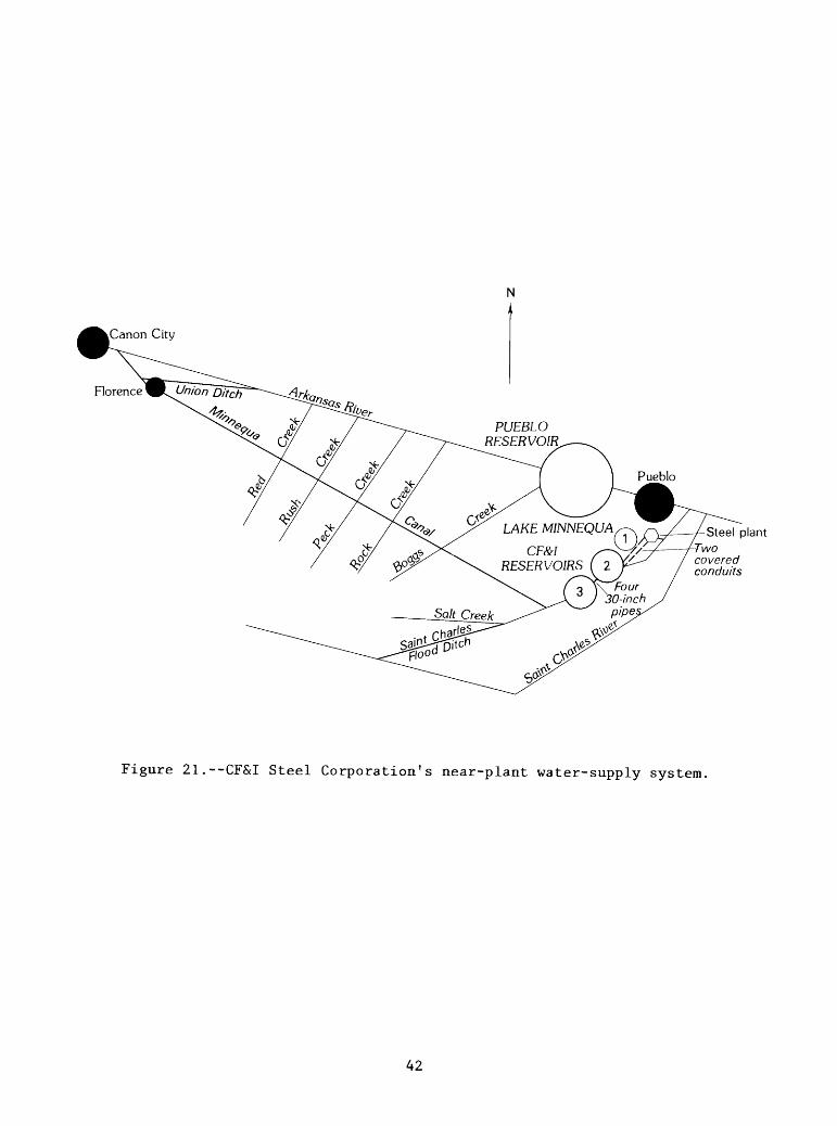
Steel plantTwocoveredconduits
Figure 21.--CF&I Steel Corporation's near-plant water-supply system.
42

The preceding summary describes water operations of CF&I Steel Corpora tion during about the last 75 years; this discussion is necessary to interpret the record of flow in the Arkansas River during that period. Beginning in late 1983, CF&I began to decrease production because of a decrease in steel prices and began to divest itself of much of its land and water holdings. Five thousand acre-feet of storage space in Turquoise Lake has been sold to the city of Aurora; additional space and water rights are currently (1983) on the market, and more are expected to be offered for sale in the future.
Multipurpose Systems
Three Federal projects and one former irrigation project, which is being transformed into multipurpose use, are located in the Arkansas River basin. The Fryingpan-Arkansas Project, built by the U.S. Bureau of Reclamation, is a storage and transmountain-diversion project, regulating agricultural water supplies, municipal water supplies, and industrial water supplies. This project also contains a flood-control pool in Pueblo Reservoir, and recreation uses in all project lakes. The other two Federal projects, John Martin Dam (see discussion of the Arkansas River Compact) and the Trinidad Dam and Reservoir Project, are primarily flood-control projects constructed by the U.S. Army Corps of Engineers. These projects also regulate irrigation water supplies, and contain recreation pools. The Twin Lakes Project is a storage and transmountain-diversion project that formerly was used only as an irri gation supply for lands irrigated by water from the Colorado Canal. In the late 1970's, ownership passed to more diversified interests, and Twin Lakes Project water now (1983) is used for multiple purposes.
Fryingpan-Arkansas Project
The Fryingpan-Arkansas Project is a multipurpose water development con structed by the U.S. Bureau of Reclamation. The project was authorized by the U.S. Congress on August 16, 1962; construction began in 1963, and virtually was complete by 1980. The chief purpose of the project is to divert unappro priated water from the western slope of Colorado for use on the more populated and water-short eastern slope. An annual average of 69,200 acre-feet, plus 3,000 acre-feet of water to be exchanged with the Twin Lakes Project, can be diverted.
The North and South Side Collection Systems (fig. 22) divert water from the headwater tributaries of Hunter Creek and the Fryingpan River, both tribu taries of the Roaring Fork River in the Colorado River basin, into the Lake Fork Arkansas River via Charles H. Boustead Tunnel. Project features located in the upstream reaches of the Arkansas River basin (fig. 15) include Turquoise Lake (behind Sugar Loaf Dam), Mount Elbert conduit, Mount Elbert forebay, Mount Elbert pumped-storage powerplant, Twin Lakes Reservoir, Pueblo Reservoir, and Fountain Valley pipeline (pi. 1). Ruedi Reservoir, located on the Fryingpan River downstream from the North and South Side Collection System, serves as replacement storage for the project.
43

South Cunningham Diversions
Busk-lvanhoe Tunnel
to Busk Creek
to Lake Fork Arkansas River
Charles H. Boustead Tunnel
Figure 22.--North and South Side Collection System, Fryingpan-Arkansas Project.
44
Water imported through Charles H. Boustead Tunnel, along with Busk- Ivanhoe Tunnel imports, Homestake Tunnel imports, and native water stored by CF&I and other entities owning or leasing storage space, are regulated in Turquoise Lake. Turquoise Lake, located 5 miles west of Leadville is the uppermost storage facility in the system. It is planned that water will be held as far upstream in the system as possible for as long as possible. Turquoise Lake should be at a low level early in the spring, before the mountain snowpack starts to melt; be filled to the annual maximum content near the end of July; and then steadily be drawn down throughout the remainder of the year, reaching a minimum content near the end of the following April. Releases from Turquoise Lake, greater than minimum-flow requirements and irrigation-diversion rights upstream from the mouth of Lake Creek, will be diverted through the Mount Elbert conduit. Halfmoon Creek also can be diverted partially into the Mount Elbert conduit. This conduit delivers water to the Mount Elbert forebay from which it goes through the Mount Elbert pumped-storage powerplant and into Twin Lakes Reservoir. Mount Elbert forebay is an 11,530-acre-foot reservoir, located just north, and about 475 feet above, Mount Elbert pumped-storage powerplant. The forebay delivers water to the powerplant through two 15-foot diameter penstocks. The Mount Elbert pumped-storage powerplant, on the north shore of Twin Lakes Reservoir, has a designed capacity of 200 megawatts. Twin Lakes Reservoir has a total storage capacity of 140,339 acre-feet, of which only 67,833 acre-feet is active.
The Mount Elbert pumped-storage powerplant is designed as a peaking plant; that is, during the peak-demand hours of the day, electricity is gener ated by waters falling from Mount Elbert forebay through the generator into Twin Lakes afterbay. During the off-peak hours of the day, the turbines are used to pump water back up the penstocks from Twin Lakes to the Mount Elbert forebay, permitting reuse during the following days' peak-demand period. Flow-through water delivered via the Mount Elbert conduit decreases the pump- back required, thus decreasing pumping cost. Storage in Twin Lakes Reservoir for the Fryingpan-Arkansas Project will be at a maximum during 1 or 2 months in the summer, and at a minimum for the remainder of the year. Exceptions to that usage occur during years of greater-than-average runoff, when carry-over storage in the system is unusually large. Twin Lakes Reservoir stores some of the system carry-over during those periods.
From Twin Lakes Reservoir, water is released into Lake Creek, then into the Arkansas River. Twin Lakes Dam has an outlet works, that eventually will be connected to a conduit, leading to a point on the terrace, across the river and above the intake to the Homestake pipeline. This conduit, when it is con nected by siphon to the Homestake pipeline, will save approximately 350 feet of hydraulic head, thus decreasing pumping cost at the Otero pumping station, when Homestake, Twin Lakes, and other waters are delivered via this route.
Fryingpan-Arkansas Project water flows from Twin Lakes to Pueblo Reser voir in the channel of the Arkansas River. The volume of water stored in Pueblo Reservoir credited to the Fryingpan-Arkansas Project is less than the volume released from Twin Lakes by the quantity of the transit loss, which currently (1983) is 0.07 percent for each mile of river channel (as decreed by the Water Court), or 9.6 percent for the 137-mile reach.
45

Pueblo Reservoir is a multipurpose facility, which can be described by its space allocation. The initial reservoir-capacity allocation (before depo sition of any of the 103,000 acre-feet of sediment expected to be deposited in the reservoir during the expected 100-year economic life) includes a 3,400- acre-foot dead pool and a 26,600-acre-foot inactive pool (together, these com prise the recreation pool); a 234,000-acre-foot active conservation pool (to regulate imported and native waters for municipal, industrial, and irrigation uses); and a 66,000-acre-foot joint-use pool. From April 15 through November 1 each year, this joint-use space must be vacated and used for flood control. The top 27,000 acre-feet of space is for inviolate flood control. There is space for about 20 feet of surcharge above the elevation of the spillway crest (4,898.7 feet) that would temporarily hold 131,500 acre-feet of flood flows.
Besides river outlets through Pueblo Dam, other outlets presently deliver water to the Fountain Valley pipeline, to Pueblo West, and to Bessemer Ditch, an irrigation canal. The Fountain Valley pipeline is a 45-mile long pipeline that delivers water from Pueblo Reservoir to the city of Colorado Springs, and the communities of Stratmoor Hills, Widefield, Security, and Fountain. Outlet works have been constructed for future developments downstream from the dam, such as a municipal outlet for a future city of Pueblo water-treatment plant, and another outlet for a proposed fish hatchery.
Pueblo Reservoir has a storage right, with an appropriation date of 1939, that would enable the Fryingpan-Arkansas Project to store and retain native water during periods of major flooding. John Martin Reservoir, located about 140 miles downstream, must be full, and all diversion rights between Pueblo and John Martin Reservoirs satisfied, before the Pueblo right would come into priority.
The Southeastern Colorado Water Conservancy District was created in 1958 by State of Colorado statutes for the purpose of developing and administering the Fryingpan-Arkansas Project. The District is the legal agency responsible for repayment of the reimbursable part of the project, not including sale of power. Project-imported water and any native water stored under the 1939 Pueblo Reservoir right is sold by the District, with the receipts used for reimbursement of project costs. The District extends along the Arkansas River from Buena Vista to Lamar, and along Fountain Creek from Colorado Springs to Pueblo. The District consists of the parts of nine counties deriving benefits from the Fryingpan-Arkansas Project. About 280,600 acres of irrigated land receive supplemental irrigation water from the Fryingpan-Arkansas Project through the District (U.S. Bureau of Reclamation, 1969).
A program planned as a part of the Fryingpan-Arkansas Project, and presently being conducted under the leadership of the Southeastern Colorado Water Conservancy District and the State Water Division 2 Engineer, is the Pueblo Winter Water Storage Program. This program permits irrigators down stream from Pueblo Dam and upstream from John Martin Reservoir to store water in Pueblo Reservoir during winter months, and to use this water during the crop-growing season. The program includes off-stream storage downstream from Pueblo, and, in past years, some storage in John Martin Reservoir. The length of time and the terms of distribution of the stored water mutually are agreed to annually by a committee of representatives of water users in the valley. A copy of a recent Winter Water Agreement is found in the Supplemental Data section at the end of this report.
46
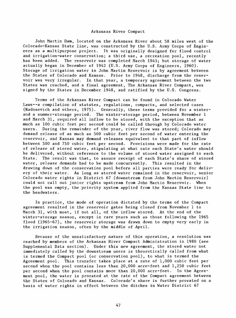
Arkansas River Compact
John Martin Dam, located on the Arkansas River about 58 miles west of the Colorado-Kansas State line, was constructed by the U.S. Army Corps of Engin eers as a multipurpose project. It was originally designed for flood control and irrigation-water conservation; a third use, a recreation pool, recently has been added. The reservoir was completed March 1943; but storage of water actually began in December of 1942 (U.S. Army Corps of Engineers, 1960). Storage of irrigation water in John Martin Reservoir is by agreement between the States of Colorado and Kansas. Prior to 1948, discharge from the reser voir was very irregular. In that year, a temporary agreement between the two States was reached, and a final agreement, The Arkansas River Compact, was signed by the States in December 1948, and ratified by the U.S. Congress.
Terms of the Arkansas River Compact can be found in Colorado Water Laws--a compilation of statutes, regulations, compacts, and selected cases (Radosevich and others, 1975). Generally, these terms provided for a winter- and a summer-storage period. The winter-storage period, between November 1 and March 31, required all inflow to be stored, with the exception that as much as 100 cubic feet per second could be called through by Colorado water users. During the remainder of the year, river flow was stored; Colorado may demand release of as much as 500 cubic feet per second of water entering the reservoir, and Kansas may demand releases equivalent to that part of inflow between 500 and 750 cubic feet per second. Provisions were made for the rate of release of stored water, stipulating at what rate each State's water should be delivered, without reference to the volume of stored water assigned to each State. The result was that, to assure receipt of each State's share of stored water, release demands had to be made concurrently. This resulted in the drawing down of the conservation pool before all parties were ready for deliv ery of their water. As long as stored water remained in the reservoir, senior Colorado water rights in District 67 (downstream from John Martin Reservoir) could not call out junior rights upstream from John Martin Reservoir. When the pool was empty, the priority system applied from the Kansas State line to the headwaters.
In practice, the mode of operation dictated by the terms of the Compact agreement resulted in the reservoir gates being closed from November 1 to March 31, with most, if not all, of the inflow stored. At the end of the winter-storage season, except in rare years such as those following the 1965 flood (1965-67), the reservoir storage was drawn down to empty very early in the irrigation season, often by the middle of April.
Because of the unsatisfactory nature of this operation, a resolution was reached by members of the Arkansas River Compact Administration in 1980 (see Supplemental Data section). Under this new agreement, the stored water not immediately called by the downstream users is theoretically called from what is termed the Compact pool (or conservation pool), to what is termed the Agreement pool. This transfer takes place at a rate of 1,000 cubic feet per second when the pool contains less than 20,000 acre-feet and 1,250 cubic feet per second when the pool contains more than 20,000 acre-feet. In the Agree ment pool, the water is prorated at the rate of the Compact agreement between the States of Colorado and Kansas. Colorado's share is further prorated on a basis of water rights in effect between the ditches in Water District 67
47

diverting water from the Arkansas River. When the theoretical release of the stored water has decreased storage in the Compact pool to zero, the reservoir is considered dry, and rights in Water District 67 are operated in priority with the river upstream from John Martin Reservoir.
Two other recent changes have been made in the operation of John Martin Reservoir. A 10,000-acre-foot permanent pool has been stored for recreation purposes, and certain canals are storing water other than Compact water in the system. Amity Canal is storing water in John Martin Reservoir that was pre viously stored in the Great Plains Reservoir system. Provisions have been made to store Fort Lyon Canal and Las Animas Consolidated Canal Company water in John Martin Reservoir. The water considered for storing by these three entities is the water stored under the approved Pueblo Reservoir winter water- storage plan. Thirty-five percent of water stored under such conditions is immediately transferred to Compact uses. All water stored is subject to a prorata share of the daily evaporation charge.
Operation under the most recent resolution is still (1983) in the explor atory stages. In response to concerns expressed by upstream water users that the theoretical transfer of water from the Compact pool to the Agreement pool went faster than under actual circumstances, a limit was placed on each Dis trict 67 ditch-storage account, above which that ditch was not allowed to call water through John Martin Reservoir. Results seem to be a more efficient use of John Martin Reservoir during the summer and in the winter storage season.
Trinidad Dam and Reservoir Project
The Trinidad Dam and Reservoir Project is a multipurpose storage project constructed by the U.S. Army Corps of Engineers on the Purgatoire River, 3 miles upstream from the city of Trinidad. Authorized in July 1958, the dam was completed in 1977.
Trinidad Dam and Reservoir provides flood protection for the city of Trinidad and for agricultural lands downstream. Regulation is provided for irrigation of 19,717 acres; prior to this project, these acres were irrigated with an erratic and ill-timed water supply. The permanent pool provides additional benefits of fish and wildlife management and recreation. Reservoir space allocation, as stated in the authorizing document (Public Law 85-500 85th Congress S.3910 July 3, 1958), is flood control, 51,000 acre-feet; irrigation, 20,000 acre-feet; joint-use, 39,000 acre-feet; and fish and recreation, 4,500 acre-feet. The joint-use pool is designed for sediment accumulation, but also will be used for irrigation-water storage, until such time as the pool is filled with sediment.
Although flood control is a nonreimbursable cost, paid for from public funds appropriated in the authorization act, the cost of the Trinidad Dam and Reservoir Project allocated to irrigation is reimbursable; that is, irrigation is expected to be self-supporting through a charge for the regulation of the water. The Purgatoire River Water Conservancy District is the entity estab lished under the laws of the State of Colorado, whose responsibility it is to regulate the irrigation supply in the Trinidad Dam and Reservoir Project, to
48

repay the reimbursable cost, and to pay irrigation's share of the operation and maintenance cost. To facilitate this repayment, a contract between the United States (acting through the U.S. Bureau of Reclamation) and the Purgatoire River Water Conservancy District is in effect. This Conservancy District operates under the Operating Principles, Trinidad Dam and Reservoir Project, and the Purgatoire River Water Conservancy District Operating Crite ria. Copies of both of these documents are reproduced in a report by the U.S. Bureau of Reclamation, (1964).
A summary of the irrigation operations of the Conservancy District follows. Water rights for the 20,000-acre-foot irrigation pool were provided by the transfer of the Model Reservoir 1908 storage decree to Trinidad Reser voir. The project has a 1950 storage decree for the joint-use pool. Trinidad Reservoir stores and regulates flows surplus to downstream requirements plus flows accruing to the Model Reservoir storage rights. Use of the project water is limited to 19,717 acres of irrigatable land, served by 11 ditch systems (fig. 20). The objective of the Conservancy District's water adminis tration is to improve the effectiveness of water use by limiting the service area to 19,717 acres of irrigatable land, and by restricting water deliveries to seasonal-crop requirements. To this purpose, the Conservancy District has control of the water rights of the 11 ditches at any time water is in the irrigation pool. When the pool is empty, operation of the ditch's rights reverts to the priority system. In conducting the regulation, the operation principles require that flow of the Purgatoire River downstream from the project area not be decreased to less than that had the Model right not been transferred. The city of Trinidad is entitled to some of the water stored under the project's decrees, but to date, the city's shares have not been put to municipal use.
Twin Lakes Project
The Twin Lakes Project transmountain diversion system was constructed in the 1930's to serve land irrigated by the Colorado Canal in Crowley County. The collection system (fig. 23) is located in eastern Pitkin County at the headwaters of the Roaring Fork River. Waters of the Roaring Fork River and Lost Man Creek are diverted through Twin Lakes Reservoir Tunnel 2 into Lincoln Gulch, and, eventually, into Grizzly Reservoir. The New York Collection Canal conveys water diverted from New York Creek and Tabor Creek, south-bank tribu taries of Lincoln Gulch to Grizzly Reservoir. From here, the water is trans ported through the Continental Divide into North Fork Lake Creek in the Twin Lakes (Independence Pass) Tunnel. The imported water is stored for later release in the 54,453 acre-feet of storage space in Twin Lakes Reservoir owned by the Twin Lakes Reservoir and Canal Company. This company also retains storage decrees for native water in Twin Lakes Reservoir. Diversions through the Twin Lakes Tunnel began on May 24, 1935. An average of 54,500 acre-feet is considered an annual supply to the Twin Lakes Project.
The site of Twin Lakes Reservoir was purchased from the Twin Lakes Reser voir and Canal Company by the U.S. Bureau of Reclamation. The reservoir has been enlarged to 140,339 acre-feet and is used by the Fryingpan-Arkansas Proj ect for storage and as an afterbay for that project's Mount Elbert powerplant.
49
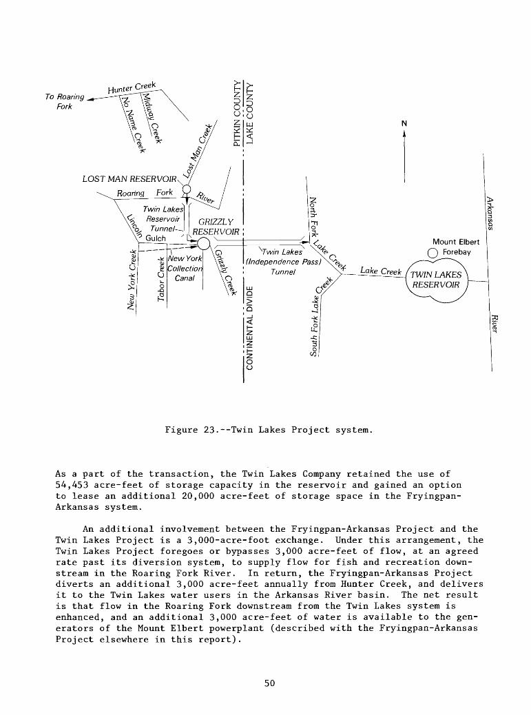
To Roaring Fork
Hunter Creek
LOST MAN RESERVOIR
Twin Lakes Reservoir
q, Tunnel- * Gulch
GRIZZLY RESERVOIR !
/vo\1
-^^\ x X"^ VW//7 Lakes X^^N
(Independence Pass)\^eV^ Tunnel\0
\\\ 7*LUQ>
Q
_i<:i-2LUZ
il-ZoCJ
\
oV^7
^[a
-4 iS0u.
-c-*^
0OD
Mount Elbert (") Fore bay
TWIN LAKESRESERVOIR
Figure 23.--Twin Lakes Project system.
As a part of the transaction, the Twin Lakes Company retained the use of 54,453 acre-feet of storage capacity in the reservoir and gained an option to lease an additional 20,000 acre-feet of storage space in the Fryingpan- Arkansas system.
An additional involvement between the Fryingpan-Arkansas Project and the Twin Lakes Project is a 3,000-acre-foot exchange. Under this arrangement, the Twin Lakes Project foregoes or bypasses 3,000 acre-feet of flow, at an agreed rate past its diversion system, to supply flow for fish and recreation down stream in the Roaring Fork River. In return, the Fryingpan-Arkansas Project diverts an additional 3,000 acre-feet annually from Hunter Creek, and delivers it to the Twin Lakes water users in the Arkansas River basin. The net result is that flow in the Roaring Fork downstream from the Twin Lakes system is enhanced, and an additional 3,000 acre-feet of water is available to the gen erators of the Mount Elbert powerplant (described with the Fryingpan-Arkansas Project elsewhere in this report).
50
In recent years, ownership of the Twin Lakes transmountain and storage system has been transferred from the irrigators of lands served by the Colo rado Canal to entities whose water use is elsewhere. The 49,588.965 outstand ing shares of Twin Lakes ownership are presently (1983) distributed as follows: 2,754.41 to Colorado Canal Irrigators; 2,434.655 to Aurora; 27,099.70 to Colorado Springs; 11,476.20 to Pueblo; 5,732.40 to Pueblo West; 91.6 to Olney Springs; 32.0 to Colorado Water Division 2 under various plans for augmentation (Jack McCullough, Twin Lakes Reservoir and Canal Company, oral commun., 1983). Aurora and Colorado Springs presently are using their shares as municipal water. Pueblo West has used some municipal water from its shares. Pueblo has not put its shares to municipal use but decides, on a year-to-year basis, whether its shares should be used in its own system, or made available to the irrigators obtaining water from the Colorado Canal. Olney Springs uses its shares in a plan for augmentation; its water, along with water from other plans for augmentation, is released to the river.
USE OF THE REPORT
The foregoing discussion describes the operation of the various Arkansas River basin water-supply systems during the past several decades. Anyone studying the flow of that river as represented in streamflow records collected during the period will need an understanding of these operations to interpret the streamflow records. In recent years there has been an acceleration in the change of the described operations. As the demand for water becomes greater due to expanding population, the patterns of water use have changed. Recent changes in CF&I Steel Corporation's water needs were described in the section on industrial users. The economic climate of agriculture is causing irriga tors in the basin to consider selling their water rights to municipalities, both in and out of the basin. The need to study the effects of these patterns of water use is the basis upon which the Arkansas River model was developed.
REFERENCES
Adkins, R.W., 1962, Water supply for an integrated steel plant at high alti tude: San Francisco, Regional Technical Meeting of American Iron andSteel Institute, Preprint, 10 p.
Arkansas River Compact Administration, 1980, Thirty-second annual report:Lamar, Colorado, 50 p.
Berry, J.W., 1959, Climates of the states, Colorado, Climatography of theUnited States No. 60-5: U.S. Weather Bureau, 16 p.
Fenneman, N.M., 1931, Physiography of the western United States: New York,McGraw-Hill, 534 p.
Luckey, R.R., and Livingston, R.K., 1975, Reservoir release routing model forthe Upper Arkansas River basin in Colorado: Denver, Colorado WaterConservation Board Water-Resources Circular 27, 44 p.
Major, T.J., Hurr, R.T., and Moore, J.E., 1970, Hydrogeologic data for thelower Arkansas River valley, Colorado: Denver, Colorado WaterConservation Board Basic-Data Release 21, 125 p.
McCullough, J.A., and Miskel, H.E., 1974, Water Resources and historical wateruse for Colorado Springs, Colorado: Colorado Springs, Resources Planningand Development Board, 60 p.
51
McHendrie, A.W., 1928, The Hatcher Ditch: Denver, Colorado State HistoricalSociety, Colorado Magazine, v. 5, no. 3, p. 81-95.
Radosevich, G.E., Hamburg, D.H., and Swick, L.L., 1975, Colorado water laws--Acompilation of statutes, regulations, compacts, and selected cases: FortCollins, Colorado State University, 3 vols.
Taylor, R.C., 1963, Colorado south of the border: Denver, Sage Press, 457 p. U.S. Army Corps of Engineers, 1960, Report on sedimentation, John Martin
Reservoir, Arkansas River basin, Colorado, Resurvey of August 1957:Albuquerque, 33 p.
U.S. Bureau of the Census, 1980, 1981, Census of population and housing,Colorado, primary population and housing counts: Washington, D.C., 8 p.
U.S. Bureau of Reclamation, 1964, Irrigation report on the Trinidad Project,Colorado, v. 1: Denver, 57 p.
______1969, Report on the Upper Arkansas River basin, Colorado, Kansas:Pueblo, Fryingpan-Arkansas Project Office, 146 p.
U.S. Geological Survey, 1970, The national atlas of the United States ofAmerica: Washington, D.C., 417 p.
U.S. Weather Bureau, 1959, Climate of the States Colorado: Washington, D.C., 16 p.
52

SUPPLEMENTAL DATA
53
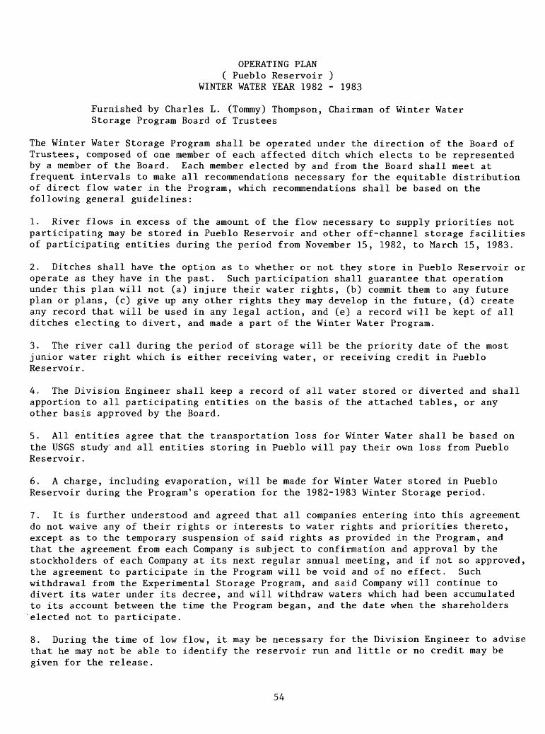
OPERATING PLAN( Pueblo Reservoir )
WINTER WATER YEAR 1982 - 1983
Furnished by Charles L. (Tommy) Thompson, Chairman of Winter Water Storage Program Board of Trustees
The Winter Water Storage Program shall be operated under the direction of the Board of Trustees, composed of one member of each affected ditch which elects to be represented by a member of the Board. Each member elected by and from the Board shall meet at frequent intervals to make all recommendations necessary for the equitable distribution of direct flow water in the Program, which recommendations shall be based on the following general guidelines:
1. River flows in excess of the amount of the flow necessary to supply priorities not participating may be stored in Pueblo Reservoir and other off-channel storage facilities of participating entities during the period from November 15, 1982, to March 15, 1983.
2. Ditches shall have the option as to whether or not they store in Pueblo Reservoir or operate as they have in the past. Such participation shall guarantee that operation under this plan will not (a) injure their water rights, (b) commit them to any future plan or plans, (c) give up any other rights they may develop in the future, (d) create any record that will be used in any legal action, and (e) a record will be kept of all ditches electing to divert, and made a part of the Winter Water Program.
3. The river call during the period of storage will be the priority date of the most junior water right which is either receiving water, or receiving credit in Pueblo Reservoir.
4. The Division Engineer shall keep a record of all water stored or diverted and shall apportion to all participating entities on the basis of the attached tables, or any other basis approved by the Board.
5. All entities agree that the transportation loss for Winter Water shall be based on the USGS study' and all entities storing in Pueblo will pay their own loss from Pueblo Reservoir.
6. A charge, including evaporation, will be made for Winter Water stored in Pueblo Reservoir during the Program's operation for the 1982-1983 Winter Storage period.
7. It is further understood and agreed that all companies entering into this agreement do not waive any of their rights or interests to water rights and priorities thereto, except as to the temporary suspension of said rights as provided in the Program, and that the agreement from each Company is subject to confirmation and approval by the stockholders of each Company at its next regular annual meeting, and if not so approved, the agreement to participate in the Program will be void and of no effect. Such withdrawal from the Experimental Storage Program, and said Company will continue to divert its water under its decree, and will withdraw waters which had been accumulated to its account between the time the Program began, and the date when the shareholders elected not to participate.
8. During the time of low flow, it may be necessary for the Division Engineer to advise that he may not be able to identify the reservoir run and little or no credit may be given for the release.
54

tn
tn
From Arkansas River Compact Administration, 19
80
AP
PE
ND
IX "
C-l
"
Reso
lutio
nC
ON
CE
RN
ING
A
N O
PE
RA
TIN
G P
LA
N F
OR
JO
HN
MA
RT
IN R
ESE
RV
OIR
WH
ER
EA
S,
the
Ark
ansa
s R
ive
r C
ompa
ct
Ad
min
istr
atio
n,
he
rein
aft
er
refe
rre
d t
o as
the
Adm
inis
tratio
n,
reco
gniz
es t
hat, b
ecau
se
of
chan
ges
in t
he r
egim
e o
f th
e A
rkansa
s R
iver,
the
pre
sent
op
era
tion
of
the
con
serv
atio
n fe
atu
res
of J
ohn
Mart
in R
ese
rvoir d
oes
not
resu
lt in
th
e m
ost
effic
ient
util
iza
tion
pos
sibl
e of
the
wa
ter
under
its c
on
tro
l;W
HE
RE
AS
, th
e A
dm
inis
tra
tion
fin
ds
tha
t ad
optio
n of
an o
pe
ratin
g
plan
th
at
esta
blis
hes
stora
ge
acco
unts
fo
r K
ansa
s, f
or
the
ditc
hes
of
Col
orad
o W
ate
r D
istr
ict
67,
and
for
oth
er
Col
orad
o di
tche
s as
pro
vided
here
in
ma
y re
sult
in m
ore
effic
ient
util
izatio
n o
f th
e w
ate
r under
its
contr
ol;
and
WH
ER
EA
S,
the
Ad
min
istr
atio
n
finds
tha
t p
rovi
sio
ns
of
the
op
era
ting
pl
an
con
tain
ed
here
in
are
pe
rmitt
ed
by
and
in c
om
plia
nce
w
ith
the
Ark
an
sas
Riv
er
Com
pact
, here
inafter
refe
rred
to
as
the
Com
pact
; an
d th
e R
ules
and
Regula
tions;
and
the
Byl
aw
s ad
opte
d by
th
e A
dm
inis
tratio
n;
NO
W
TH
ER
EF
OR
E,
BE
IT
R
ES
OL
VE
D
that
the
Adm
inis
tratio
n
appr
oves
and
ado
pts
the
follo
win
g o
pera
ting p
lan
:I.
Defin
itions:
A.
"Pe
rio
ds
of
win
ter
sto
rag
e"
cons
ists
of
the
perio
d of
time
co
mm
en
cin
g o
n N
ove
mber
1 of
eac
h ye
ar
and
con
tinu
ing
to
the
firs
t ex
haus
tion
of
con
serv
atio
n
sto
rag
e
du
rin
g
the
com
pact
ye
ar.
B.
"Sum
mer
stora
ge
seaso
n"
sha
ll be
th
e period o
f tim
e c
om
me
nci
ng
at
th
e firs
t e
xha
ust
ion
of
con
serv
atio
n
stor
age
and
contin
uin
g t
o an
d in
cludin
g t
he n
ext
succ
eedi
ng O
ctob
er 3
1C
. "I
nflo
ws"
incl
ude a
ll th
e norm
al
acc
retio
ns
into
Joh
n M
art
in
Re
serv
oir,
mea
sure
d or
oth
erw
ise,
incl
udin
g r
iver
flow
but
not
in
clu
din
g
deliv
eries
into
th
e perm
anent
pool
or
d
eliv
erie
s of
o
the
r w
ate
r as
sub
sequ
ently
de
fine
d h
ere
in.
D.
"Co
nse
rva
tion
st
ora
ge"
is w
ate
r st
ored
in
th
e co
nse
rva
tion
po
ol
that,
but
for
the
adop
tion
of
this
re
solu
tion,
wou
ld
have
co
mp
rise
d o
f th
e b
en
efit
s arisi
ng f
rom
the
co
nst
ruct
ion
of
John
M
art
in R
ese
rvoir.
E.
"Oth
er
wate
r"
for
regula
tion
by
John
M
art
in
Rese
rvoir
is
wa
ter
deliv
ere
d
into
th
e ac
coun
ts
esta
blis
hed
in
Sec
tion
111,
h
ere
in,
and
deliv
ere
d
under
the
au
tho
rity
of
pre-
Com
pact
C
olor
ado
wate
r rig
hts
. D
eliv
erie
s of
oth
er
wa
ter
are
pe
rmitt
ed
to
ga
in i
ncr
ease
d u
tiliz
atio
n a
nd g
rea
ter
be
ne
ficia
l us
e.F
. "C
om
pact
ye
ar"
is
th
e w
ate
r a
cco
un
ting
ye
ar
of
the
Ad
min
istr
atio
n;
it c
omm
ence
s on
No
vem
be
r 1
of
each
year
and
exte
nds
to a
nd i
ncl
udes
the
ne
xt s
ucce
edin
g O
ctob
er 3
1.G
. E
xcept
as p
rovi
ded h
ere
in,
all
wo
rds
and
term
s us
ed i
n th
is
reso
lutio
n h
ave
the
meanin
g p
resc
ribed i
n C
om
pa
ct A
rtic
le 1
11.
II.
Opera
ting P
rin
cip
les:
A.
Period o
f W
inte
r S
tora
ge
- A
ll in
flow
s in
to
John
M
art
in
Rese
rvoir
du
rin
g
a ,
3rio
d of
win
ter
stor
age
sha
ll acc
rue
to
con
serv
atio
n
stor
age.
C
on
serv
atio
n s
tora
ge s
ha
ll be
rel
ease
d in
to t
he a
ccou
nts
spe
cifie
d i
n S
ubse
ctio
n II
D b
eg
inn
ing
at
the
firs
t re
quest
for
rele
ase
after
Marc
h 3
1 of
acc
ou
nt
wate
r by
a C
olor
ado
Wa
ter
Dis
tric
t 67
ditc
h
or
by
Kan
sas
or
begin
nin
g a
t 8:
00 a
.m.
on A
pril
7, w
hic
he
ver
occu
rs f
irst
. B
. S
um
me
r S
tora
ge S
easo
n
(1)
Whe
n a
runoff e
vent
o
ccu
rs d
urin
g
the
sum
me
r st
orag
e se
ason
, su
ch
that
inflo
ws
into
Joh
n M
art
in
Rese
rvoir are
ex
pe
cted
to
ex
ceed
th
en
exi
stin
g
irrigation re
quirem
ents
of
the
ditc
hes
in C
olor
ado
Wa
ter
Dis
tric
t 67
by
at
lea
st 1
,000
acr
e-f
eet,
then
th
e ga
tes
on J
ohn
Mart
in R
ese
rvo
ir s
hall
be c
lose
d co
m
menci
ng
con
serv
atio
n
stora
ge
exce
pt
for
rele
ases
of
acco
unt
wa
ter
pu
rsu
an
t to
Sub
sect
ion
II
E,
here
in.
(2)
The
ditc
hes
in C
olor
ado
Wate
r D
istr
ict
67 w
ill b
e re
move
d
fro
m t
he C
olor
ado
priority
sys
tem
whe
n th
e su
m o
f th
e flo
ws
of
the
Ark
ansa
s R
ive
r at
the
Las
Anim
as
ga
gin
g s
tatio
n
and
the
Pu
rga
toire
Riv
er
at
the
Las
Anim
as
ga
gin
g s
tatio
n,
exc
lusi
ve o
f se
pa
rate
deliv
eries
of
oth
er
wa
ter
under
Sec
tion
III,
h
ere
in,
ind
ica
tes
that
con
serv
atio
n s
tora
ge w
ill o
ccu
r.(3
) A
ll in
flow
s ente
ring
said
re
serv
oir
du
rin
g
a period
of
con
serv
atio
n s
tora
ge i
n th
e su
mm
er
stora
ge s
easo
n sh
all
acc
rue
to c
on
serv
atio
n s
tora
ge.
Con
serv
atio
n st
ora
ge s
hall
be r
elea
sed
into
the
acc
ount
s sp
eci
fied
in
Sec
tion
II D
begin
nin
g a
t th
e firs
t re
ques
t fo
r re
leas
e of
ac
coun
t w
ate
r by
a
Col
orad
o W
ate
r D
istr
ict
67
ditc
h
or
by
Kan
sas
or
begin
nin
g
48
ho
urs
after
com
mence
ment
of
con
serv
atio
n
sto
rag
e,
whic
heve
r o
ccu
rs
first
. C
. E
xha
ust
ion
of
Con
serv
atio
n S
tora
ge
(1
) F
or
the
purp
oses
of
Com
pact
A
rtic
le
V F
, th
e co
n
serv
atio
n
pool
sh
all
be
deem
ed
exha
uste
d w
heneve
r co
n
serv
atio
n
stora
ge
has
been
co
mp
lete
ly
rele
ased
in
to
the
ac
coun
ts.
Whe
n th
is o
ccur
s, C
olor
ado
sha
ll adm
inis
ter
the
decr
eed
rights
of
wate
r us
ers
in C
olor
ado
Wa
ter
Dis
tric
t 67
as
ag
ain
st
each
oth
er
and
as a
ga
inst
all
rights
now
or
here
after
decr
eed
to
wa
ter
user
s d
ive
rtin
g u
pst
rea
m f
rom
Joh
n M
art
in D
am o
n th
e ba
sis
of
rela
tive
p
rio
ritie
s in
the
sam
e m
anner
in w
hic
h t
heir
resp
ect
ive p
rio
rity
rig
hts
wer
e a
dm
inis
tere
d b
efo
re J
ohn
Mart
in
Rese
rvoir b
egan
to
opera
te a
nd a
s th
ough
Joh
n M
art
in D
am h
ad
not
been
co
nst
ruct
ed
. H
owev
er,
du
rin
g
thes
e tim
es,
in
flow
s sh
all,
to
the
e
xte
nt
pra
ctic
al,
be m
ea
sure
d a
nd r
elea
sed
fro
m
the
rese
rvo
ir w
itho
ut
tem
po
rary
sto
rage o
r a
vera
gin
g f
low
s, a
nd
con
serv
atio
n s
tora
ge m
ay
not
be a
ccu
mu
late
d n
or
ma
y st
ora
ge
in t
he a
ccou
nts
be i
ncre
ased
exc
ept
by
deliv
eries
of o
ther
wa
ter
unde
r S
ectio
n II
I, h
ere
in.
(2)
Ad
min
istr
atio
n
in C
olor
ado
un
de
r de
cree
d p
rio
ritie
s sh
all
be
initi
ate
d
so
that
ditc
hes
upst
ream
fr
om
Jo
hn
Mart
in
Re
serv
oir
sha
ll deliv
er
to
the
prio
ritie
s of
Col
orad
o W
ate
r D
istr
ict
67
ditc
hes
wa
ter
at
the
Ark
an
sas
Riv
er
at
the
Las
An
ima
s g
ag
ing
st
atio
n
coin
cid
en
t w
ith
the
exha
ustio
n of
th
e co
nse
rva
tion
st
ora
ge
whe
n ta
king
the
flow
of
all
wa
ters
, in
cl
ud
ing
th
at
of
the
Purg
ato
ire
Riv
er,
in
to
ap
pro
pria
te
con
si
dera
tion.
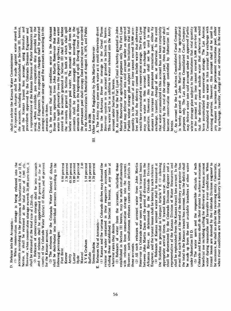
Ln
D.
Rel
ease
int
o th
e A
ccou
nts
(1)
Whe
n co
nser
vatio
n st
orag
e is
be
ing
rele
ased
in
to
the
acco
unts
acc
ordi
ng t
o th
e pr
ovis
ions
of
Subs
ectio
ns I
I A
or I
I B,
he
rein
, it
shal
l be
re
leas
ed
at
the
tota
l ra
te
of
1.00
0 cf
s H
owev
er,
whe
n co
nser
vatio
n st
orag
e ex
ceed
s 20
,000
acr
e fe
et,
it sh
all
be r
elea
sed
at t
he t
otal
rat
e of
1,2
50 c
fs.
(2)
Rel
ease
s of
con
serv
atio
n st
orag
e sh
all
be i
nto
acco
unts
an
d sa
id
rele
ases
sh
all
be a
ppor
tione
d 60
per
cent
for
(ho
ac
coun
ts o
f th
e C
olor
ado
Wat
er D
istr
ict
07 d
itch
es a
nd 4
0 pe
rcen
t fo
r th
e K
ansa
s ac
coun
t.(3
) T
he
rele
ases
fo
r th
e C
olor
ado
Wat
er D
istr
ict
67
ditc
hes
shal
l be
di
stri
bute
d in
to
indi
vidu
al
acco
unts
acc
ordi
ng t
o th
e fo
llow
ing
perc
enta
ges:
Fort
Ben
t 9.
90 p
erce
nt
Kee
see
2.30
per
cent
A
mity
49
50
perc
ent
Lam
ar
19.8
0 pe
rcen
t H
yde
....
....
....
....
....
....
..........
l .30
per
cent
Man
vel
............................
....
....
....
....
...
2.40
X-Y
& G
raha
m ....................
....
....
....
..
5.10
per
cent
Buf
falo
........................
....
....
....
...
8.50
per
cent
Siss
on-S
tubb
s ..
....
....
....
....
....
....
....
....
..
1.20
per
cent
E.
Rel
ease
s O
ut o
f A
ccou
nts
(1)
Kan
sas
and
the
vari
ous
Col
orad
o di
tche
s m
ay d
eman
d th
e re
leas
e of
w
ater
co
ntai
ned
in
thei
r re
spec
tive
ac
coun
ts,
in
clud
ing
thos
e es
tabl
ishe
d in
Sec
tion
III
here
in,
at a
ny t
ime
at
wha
teve
r ra
tes
they
des
ire.
(2)
Rel
ease
s of
w
ater
fr
om
the
acco
unts
, in
clud
ing
thos
e es
tabl
ishe
d in
Sec
tion
III
here
in,
may
be
mad
e si
mul
tane
ousl
y w
ith
rele
ases
fr
om
cons
erva
tion
stor
age
into
th
e ac
coun
ts.
How
ever
, su
ch s
imul
tane
ous
rele
ases
can
not
crea
te d
efic
its i
n th
ose
acco
unts
.(3
) A
ll su
ch
rele
ases
of
ac
coun
t w
ater
fr
om
John
M
artin
R
eser
voir
to
Col
orad
o w
ater
use
rs a
re s
ubje
ct t
o tr
ansi
t lo
sses
be
twee
n Jo
hn M
artin
Dam
and
the
poi
nt o
f di
vers
ion
from
the
A
rkan
sas
Riv
er,
as
dete
rmin
ed
by
the
Col
orad
o D
ivis
ion
Eng
inee
r, a
nd t
he t
rans
it l
osse
s sh
all
be b
orne
by
such
rel
ease
s.(4
) R
elea
ses
of K
ansa
s ac
coun
t w
ater
sha
ll be
mea
sure
d at
th
e St
atel
ine
as p
rovi
ded
in C
ompa
ct A
rtic
le V
E
(3)
allo
win
g ap
prop
riat
e ar
riva
l tim
es.
If t
rans
it l
osse
s oc
cur,
tho
se l
osse
s sh
all
be d
eter
min
ed b
y th
e C
olor
ado
Div
isio
n E
ngin
eer
and
a re
pres
enta
tive
of
the
Kan
sas
Div
isio
n of
Wat
er R
esou
rces
and
sh
all
be r
eple
nish
ed f
rom
the
Kan
sas
tran
sit
loss
acc
ount
. In
the
ev
ent
that
suc
h lo
sses
at
the
end
of t
he d
eliv
ery
are
grea
ter
than
th
e to
tal
in t
he K
ansa
s tr
ansi
t lo
ss a
ccou
nt,
then
the
def
icit
shal
l be
mad
e up
fro
m
the
next
ava
ilab
le t
rans
fers
of
othe
r w
ater
un
der
Subs
ectio
n II
I D
.(5
) T
he
wat
er
user
s an
d th
e re
spon
sibl
e of
fici
als
of
both
C
olor
ado
and
Kan
sas
shal
l do
the
ir u
tmos
t to
ach
ieve
max
imum
be
nefi
cial
use
inc
ludi
ng c
allin
g fo
r de
live
ries
of
Kan
sas
acco
unt
wat
er d
urin
g re
ason
able
and
fav
orab
le r
iver
con
ditio
ns.
Whe
n tr
ansi
t lo
sses
are
dee
med
by
the
Col
orad
o D
ivis
ion
engi
neer
to
be e
xces
sive
, he
sha
ll so
adv
ise
the
rece
ivin
g en
tity.
Con
vers
ely,
w
hen
rive
r co
nditi
ons
are
favo
rabl
e fo
r a
deliv
ery
to K
ansa
s, h
e
shal
l so
adv
ise
the
Kan
sas
Wat
er C
omm
issi
oner
.F.
Eva
pora
tion
char
ges
shal
l be
mad
e ag
ains
t w
ater
sto
red
in
the
acco
unts
, in
clud
ing
thos
e es
tabl
ishe
d in
Sec
tion
III,
here
in,
and
the
Kan
sas
tran
sit
loss
ac
coun
t, us
ing
form
ulas
an
d pr
oced
ures
ap
prov
ed
by t
he C
olor
ado
Div
isio
n E
ngin
eer
and
a re
pres
enta
tive
of
the
Kan
sas
Div
isio
n of
Wat
er R
esou
rces
and
us
ing,
w
hen
avai
labl
e,
pan
evap
orat
ion
data
pr
ovid
ed b
y th
e C
orps
of
Eng
inee
rs.
The
eva
pora
tion
char
ges
shal
l be
pro
rate
d am
ongs
t co
nser
vati
on s
tora
ge a
nd t
he a
ccou
nts
acco
rdin
g to
the
am
ount
s in
the
m.
G.
In
the
even
t th
at
runo
ff
cond
ition
s oc
cur
in t
he A
rkan
sas
Riv
er b
asin
ups
trea
m
from
Joh
n M
artin
Res
ervo
ir t
hat
caus
e w
ater
to
spill
phy
sica
lly o
ver
the
proj
ect's
spi
llway
, th
en w
ater
st
ored
in
the
acco
unts
gra
nted
in
Sect
ion
III
shal
l sp
ill b
efor
e th
e ac
coun
ts
gran
ted
in
Sect
ion
II,
both
of
whi
ch
shal
l sp
ill
befo
re c
onse
rvat
ion
pool
wat
er.
The
am
ount
of
spill
fr
om t
he
acco
unts
sh
all
be
pror
ated
am
ongs
t th
em
acco
rdin
g to
th
e am
ount
s in
the
m a
t th
e be
ginn
ing
of s
pill.
Dur
ing
tim
es o
f sp
ill,
the
perm
anen
t po
ol s
hall
occu
py f
lood
con
trol
spa
ce a
s pr
ovid
ed
in t
he A
dmin
istr
atio
n's
Res
olut
ion
of A
ugus
t 14
, 19
76, a
nd P
ublic
L
aw 8
9-29
8.
III.
Oth
er W
ater
for
Reg
ulat
ion
by J
ohn
Mar
tin R
eser
voir
:A
. T
he A
mity
may
sto
re s
uch
wat
er a
s it
coul
d ot
herw
ise
dive
rt
from
th
e A
rkan
sas
Riv
er
for
stor
age
in
the
Gre
at
Pla
ins
Res
ervo
ir s
yste
m
in i
ts a
ccou
nt g
rant
ed i
n Se
ctio
n II
, he
rein
. T
his
wat
er w
ill b
e in
add
ition
to
wat
er r
elea
sed
into
the
Am
ity
acco
unt
unde
r Se
ctio
n II
, he
rein
.B.
An
acco
unt
for
the
For
t Ly
on C
anal
is
here
by g
rant
ed i
n Jo
hn
Mar
tin R
eser
voir
for
agr
icul
tura
l pu
rpos
es o
nly.
The
For
t Ly
on
Can
al m
ay d
eliv
er w
ater
int
o sa
id a
ccou
nt u
nder
an
appr
oved
Pu
eblo
win
ter
stor
age
plan
sub
ject
to
the
limita
tions
tha
t to
tal
quan
tity
in t
he a
ccou
nt a
t an
y ti
me
cann
ot e
xcee
d 20
.000
acr
e-
feet
and
tha
t th
e de
liver
y ca
nnot
inc
lude
wat
er t
hat
othe
rwis
e w
ould
hav
e ac
cum
ulat
ed i
n co
nser
vatio
n st
orag
e. T
he F
ort
Lyon
m
ay
use
wat
er
in
this
ac
coun
t fo
r ex
chan
ge
with
ex
istin
g pr
iori
ties.
H
owev
er,
this
ac
coun
t sh
all
not
be
used
in
an
y m
anne
r to
inc
reas
e th
e pe
rman
ent
recr
eati
on p
ool,
eith
er b
y ex
chan
ge,
tran
sfer
, ch
ange
of
use,
or
othe
rwis
e.
In t
he e
vent
th
at w
ater
acc
umul
ated
in
this
acc
ount
has
not
bee
n co
mpl
etel
y re
leas
ed b
y th
e en
d of
the
com
pact
yea
r, t
hen
that
wat
er s
hall
beco
me
cons
erva
tion
stor
age
cont
rolle
d by
Su
bsec
tion
II
A,
here
in.
C.
An
acco
unt
for
the
Las
Ani
mas
Con
solid
ated
Can
al C
ompa
ny
is
here
by
gran
ted
in
John
M
artin
Res
ervo
ir f
or a
gric
ultu
ral
purp
oses
on
ly.
The
L
as A
nim
as
Con
solid
ated
Can
al C
ompa
ny
may
del
iver
wat
er i
nto
said
acc
ount
und
er a
n ap
prov
ed P
uebl
o w
inte
r st
orag
e pl
an s
ubje
ct t
o th
e lim
itatio
ns t
hat
tota
l qu
anti
ty
in
the
acco
unt
at a
ny t
ime
cann
ot e
xcee
d 5,
000
acre
-fee
t an
d th
at
the
deliv
ery
cann
ot
incl
ude
wat
er
that
oth
erw
ise
wou
ld
have
ac
cum
ulat
ed
in
cons
erva
tion
stor
age.
T
he
Las
A
nim
as
Con
solid
ated
may
use
wat
er i
n th
is a
ccou
nt f
or e
xcha
nge
with
ex
istin
g pr
iori
ties.
H
owev
er,
this
acc
ount
sha
ll no
t be
use
d in
an
y m
anne
r to
inc
reas
e th
e pe
rman
ent
recr
eati
on p
ool,
eith
er
by e
xcha
nge,
tra
nsfe
r, c
hang
e of
use
, or
oth
erw
ise.
In
the
even
t

that
wat
er a
ccum
ulat
ed i
n th
is a
ccou
nt h
as n
ot b
een
com
plet
ely
rele
ased
by
the
end
of t
he c
ompa
ct y
ear,
the
n th
at w
ater
sha
ll be
com
e co
nser
vatio
n st
orag
e co
ntro
lled
by S
ubse
ctio
n II
A.
D.
Thi
rty-
five
pe
rcen
t of
al
l w
ater
de
liver
ies
to
John
M
artin
R
eser
voir
, un
der
Subs
ectio
ns
III
A,
III
B, a
nd
III
C, h
erei
n,
duri
ng a
ny c
ompa
ct y
ear
shal
l be
tra
nsfe
rred
int
o th
e ac
coun
ts
for
Kan
sas
tran
sit
loss
es,
for
Kan
sas,
and
for
Col
orad
o W
ater
D
istr
ict
67
ditc
hes
at
the
time
of
deliv
ery
in
the
follo
win
g m
anne
r. F
irst
, tr
ansf
ers
from
del
iver
ies
shal
l m
ake
up d
efic
its,
if an
y,
in
the
Kan
sas
tran
sit
loss
ac
coun
t w
hich
re
sult
fro
m
Subs
ectio
n II
E
(4
), he
rein
, an
d sh
all
then
als
o fil
l th
e sa
id
Kan
sas
tran
sit
loss
ac
coun
t to
the
am
ount
of
1,70
0 ac
re f
eet.
The
n,
of a
ll su
ch
wat
er d
eliv
ered
in
exc
ess
of
this
spe
cifi
ed
amou
nt,
11 p
erce
nt o
f th
ose
deliv
erie
s sh
all
be t
rans
ferr
ed t
o th
e K
ansa
s ac
coun
t an
d 24
pe
rcen
t of
th
ose
deliv
erie
s sh
all
be
tran
sfer
red
to t
he a
ccou
nt o
f th
e C
olor
ado
Wat
er
Dis
tric
t 67
di
tche
s. T
rans
fers
int
o th
e ac
coun
ts f
or C
olor
ado
Wat
er D
istr
ict
67 d
itche
s sh
all
be d
istr
ibut
ed a
ccor
ding
to
the
perc
enta
ges
in
Subs
ectio
n II
D (
3),
here
in;
exce
pt t
he A
mity
sha
ll no
t sh
are
in
dist
ribu
tions
of
deliv
erie
s un
der
Subs
ectio
n II
I A
, he
rein
.IV
. A
perm
anen
t re
crea
tion
poo
l ha
s be
en a
utho
rize
d by
the
Aug
ust
14,
1976
, R
esol
utio
n of
the
Adm
inis
trat
ion.
For
pur
pose
s of
the
R
esol
utio
n, t
his
perm
anen
t re
crea
tion
poo
l sh
all
be c
onsi
dere
d a
sepa
rate
acc
ount
and
del
iver
ies
mad
e to
it
are
not
subj
ect
to t
he
tran
sfer
s pr
ovid
ed
in S
ubse
ctio
n II
I D
, he
rein
. T
he
perm
anen
t re
crea
tion
po
ol
will
, ho
wev
er,
stan
d its
pr
o ra
ta
shar
e of
ev
apor
atio
n as
pr
ovid
ed
in
the
adm
inis
trat
ion'
s R
esol
utio
n of
A
ugus
t 14
, 19
76.
V.
In t
he e
vent
of
inju
ry e
ithe
r to
ent
ities
in
Col
orad
o or
to
Kan
sas,
th
ere
shal
l be
res
titu
tion
fro
m t
he f
irst
acc
ount
wat
er t
here
afte
r av
aila
ble
from
th
e en
tity
rece
ivin
g im
prop
er
bene
fits
. T
he
engi
neer
ing
com
mit
tee
shal
l qu
antif
y su
ch i
njur
y, s
ubje
ct t
o th
e ap
prov
al o
f th
e A
dmin
istr
atio
n.V
I. A
dopt
ion
of
this
re
solu
tion
does
no
t pr
ejud
ice
the
abili
ty
of
Kan
sas
or
of
any
Col
orad
o di
tch
to
obje
ct
or
to
othe
rwis
e re
pres
ent
its i
nter
est
in p
rese
nt o
r fu
ture
cas
es o
r co
ntro
vers
ies
befo
re t
he A
dmin
istr
atio
n or
in
a co
urt
of c
ompe
tent
jur
isdi
ctio
n.V
II.
Thi
s ag
reem
ent
shal
l be
, an
d co
ntin
ue t
o be
, in
ful
l fo
rce
and
effe
ct f
rom
and
aft
er t
he d
ate
of e
xecu
tion
of t
his
reso
lutio
n un
til
Mar
ch
31,
1981
, an
d ye
ar
to
year
th
erea
fter
su
bjec
t to
th
e fo
llow
ing
prov
isio
ns:
A. N
ot
late
r th
an
Nov
embe
r 15
of
ea
ch
year
, th
e C
olor
ado
Div
isio
n E
ngin
eer
shal
l m
ake
an a
ccou
ntin
g of
the
ope
ratio
n un
der
this
res
olut
ion
for
the
prev
ious
com
pact
yea
r av
aila
ble
to
the
Ope
ratio
ns
Com
mitt
ee
of
the
Adm
inis
trat
ion
and
to
in
tere
sted
par
ties
. E
ithe
r C
olor
ado
or K
ansa
s, t
hrou
gh i
ts c
om
pact
del
egat
ion,
may
the
n te
rmin
ate
this
res
olut
ion
on t
he n
ext
succ
eedi
ng
Mar
ch
31
by
givi
ng
wri
tten
notic
e to
th
e ad
m
inis
trat
ion
by F
ebru
ary
1 of
the
sam
e co
mpa
ct y
ear.
B.
In
the
even
t th
is
reso
lutio
n is
so
te
rmin
ated
, th
en
entit
ies
stor
ing
wat
er i
n ac
coun
ts p
rior
to
such
ter
min
atio
n m
ay u
tiliz
e su
ch
wat
er
duri
ng
the
next
ir
riga
tion
seas
on
unde
r th
e pr
ovis
ions
of
this
res
olut
ion.
Wat
er n
ot u
tiliz
ed b
y th
e fo
llow
ing
Nov
embe
r I
shal
l re
vert
to
cons
erva
tion
stor
age.
VII
I. T
his
reso
lutio
n su
pers
edes
in
its
en
tire
ty
the
agre
emen
t of
D
ecem
ber
12,
1978
, co
ncer
ning
Am
ity-G
reat
P
lain
s w
ater
and
th
e R
esol
utio
n co
ncer
ning
an
Inte
rim
Ope
ratin
g P
lan
for
John
M
artin
R
eser
voir
ent
ered
in
to o
n M
arch
21
, 19
80.
All
wat
er
deliv
ered
int
o th
e ac
coun
ts e
stab
lish
ed u
nder
the
aut
hori
ties
of
thes
e tw
o re
solu
tions
sha
ll be
for
war
ded
and
cred
ited
, w
ithou
t de
duct
ions
, to
th
e ac
coun
ts
for
the
sam
e en
titi
es
that
ar
e es
tabl
ishe
d in
thi
s op
erat
ing
plan
.
Ent
ered
thi
s 24
th d
ay o
f A
pril,
198
0, b
y sp
ecia
l te
leph
onic
mee
ting.
/s/
Fra
nk G
. C
oole
yC
hair
man
Ark
ansa
s R
iver
Com
pact
Adm
inis
trat
ion
/s/
Leo
Idle
r S
ecre
tary
Ark
ansa
s R
iver
Com
pact
A
dmin
istr
atio
n
(SE
AL
)

Table 2. Conduits in the area
Map,. number Name
onplate 1
Cunningham conduit 1 -- Fountain Valley
pipeline.Fryingpan conduit 1 -----Granite siphon 1 --------Homestake pipeline-----
Montgomery pipeline----Monument Lake pipeline-Mormon conduit !--------Mount Elbert conduit---North Lake pipeline----Sawyer conduit 1 --------South Cunningham
conduit 1 .Walsenburg pipeline----
12
345
6789
101112
13
LocationSec tion
27157
231628
1432158
322327
28
Town ship
8s15s15s9s9s12s
13s32s8s11s32s9s8s
29s
Range Prime meridian
82w66w65w82w82w68w
69w68w82w80w68w83w82w
68w
666666
66666
6
6
0.38.7.0.0.
5026
702.0.
10,2.0.0,
1.
Length (miles)
.8
.2 (trunk)
.6(lateral)
.5
.7
.2
.3
.7
.5
.6
.7
.7
Diameter (inches)
6033,39,4214,248430,366648
30 4590--2718,21,24
16
Use
Multiple purposeMunicipal
Multiple purposeMultiple purposeMunicipal
MunicipalMunicipalMultiple purposeMultiple purposeMunicipalMultiple purposeMultiple purpose
Municipal
Operator
Fryingpan-ArkansasFryingpan-Arkansas
Fryingpan-ArkansasFryingpan-ArkansasHomestake Project
Blue River ProjectCity of TrinidadFryingpan-ArkansasFryingpan-ArkansasCity of TrinidadFryingpan-ArkansasFryingpan-Arkansas
City of Walsenburg
ProjectProject
ProjectProject
ProjectProject
ProjectProject
1 Conduit located outside the Arkansas basin.
58
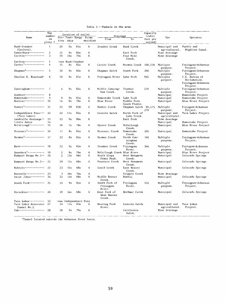
Table 3.--Tunnels in the area
Map Capacityf Location of outlet _ ,r , .
number = =; =: - Drainage (cubic ,. ..Name Sec- Town- Range Prime = fi = ,. Use Operatoron e ... From To feet per
. n tion ship meridian ... _________________plate 1___________________________________________________second)______________________________
Busk-Ivanhoe 1 20 9s 81w 6 Ivanhoe Creek Busk Creek Municipal and Pueblo and(Carlton). agricultural. Highline Canal.
Canterbury---------- 2 12 9s 80w 6 East Fork Mine drainageCarlton------------- 3 10 16s 70w 6 Four Mile Mine drainage
Creek. Carlton-------- --- 1 -see Busk-Ivanhoe
Carter 1 - - ----- 4 15 8s 82w 6 Carter Creek Mormon Creek 100,130 Multiple Fryingpan-Arkansaspurpose. Project.
Chapman 1 ------------ 5 30 9s 82w 6 Chapman Gulch South Fork 300 Multiple Fryingpan-Arkansaspurpose. Project.
Charles H. Boustead- 6 10 9s 8lw 6 Fryingpan River Lake Fork 945 Multiple U.S. Bureau ofpurpose. Reclamation.
Fryingpan-ArkansasProject.
Cunningham---------- 7 4 9s 82w 6 Middle Cunning- Ivanhoe 270 Multiple Fryingpan-Arkansasham Creek. Creek. purpose. Project.
Goddard------------- 8 Municipal Homestake ProjectHomestake----------- 9 9 9s 8lw 6 Homestake Creek Lake Fork Municipal Homestake ProjectHoosier------------- 10 14 8s 78w 6 Blue River Middle Fork Municipal Blue River Project
South Platte. Hunter 1 - - -- 11 23 9S 83W 6 Hunter Creek Chapman Gulch 90,175 Multiple Fryigpan-Arkansas
270 purpose. Project. Independence Pass--- 12 22 11s 82w 6 Lincoln Gulch North Fork of Municipal and Twin Lakes Project
(Twin Lakes) Lake Creek. agricultural. Leadville drainage-- 13 13 9s 80w 6 East Fork Mine drainageLittle Annie 14 Municipal Homestake Project McCullough 1 --------- 15 26 7s 78w 6 Spruce Creek McCullough Municipal Blue River Project
Creek. Missouri 1 ----------- 16 17 8s 8lw 6 Missouri Creek Homestake 300 Municipal Homestake Project
Creek. Mormon 1 ------------- 17 22 8s 82w 6 Mormon Creek North Cun- 190 Multiple Fryingpan-Arkansas
ningham purpose. Project. Creek.
Nast---------------- 18 23 9s 82w 6 Ivanhoe Creek Fryingpan 360 Multiple Fryinpan-ArkansasRiver. purpose. Project.
Quandary 1 --- - -- 19 2 8s 78w 6 McCullough Creek Blue River Municipal Blue River Project Rampart Range No.l-- 20 2 13s 68w 6 North Slope West Monument Municipal Colorado Springs
Pikes Peak. Creek. Rampart Range No.2-- 21 28 12s 68w 6 Fountain Creek West Monument Municipal Colorado Springs
Creek. Roberts------------- 22 23 15s 68w 6 Gould Creek East Beaver Municipal Colorado Springs
Creek. Roosvelt------------ 23 3 16s 70w 6 Cripple Creek Mine drainageSaint Johns--------- 24 32 14s 68w 6 Middle Beaver Ruxton Municipal Colorado Springs
Creek.South Fork-- --- 25 23 9s 82w 6 South Fork of Fryingpan 450 Multiple Fryingpan-Arkansas
Fryingpan River. purpose. Project. River.
Strickler---- --- 26 19 14s 68w 6 East Fork of Boehmer Creek Municipal Colorado SpringsWest Beaver Creek.
Twin Lakes---------- 12 -see Independence PassTwin Lakes Reservoir 27 14 11s 83w 6 Roaring Fork Lincoln Gulch Municipal and Twin Lakes
Tunnel No.2. River. agricultural. Project. Yak- ---- ------ 28 30 9s 79w 6 California Mine drainage
Gulch.
1Tunnel located outside the Arkansas River basin.
59

Table A. --Major ditches in the area
Map i number Name 1
onplate 2
Baca Joint (Picketwire) .
Baldwin-Stubbs
Beaver Dam (Younger No. 1) .
Brewer & Kelso---- Brush Hollow
Supply. Buena Vista
Smelting.
Burns and Duncan--
Canon City - Oil Creek.
Canon City Water Works .
Cherry Creek Ditch
Clayborn Extension
Colorado Canal----
DeWeese - Dye Derry No. 1 .
1 2 3 A
5
6
7 8 9
10
11 12
13
1A 15
16
17 18
19
20 21 22
232A
26 27 28 29
30
31
32 33I/:
LocationSec tion
03 36 36 13
18
29
29 36 5
22
21 16
09
26 12
1
32 32
31
19 3A1
7 25
23 9 10 9
1 1691
Town
ship
23s 22s 20s 33s
22s
9s
9s 20s 21s
lAs
19s 18s
lAs
22s 32s
33s
18s 18s
18s
2£s 10s 33s
33s 15s
lAs 21s 21s 8s
19s 10sQc
Range Prime meridian
A9w A8w 6Aw 6Aw
58w
80w
80w 66w 6 Aw
78w
68w 68w
78w
4 Aw 62w
69w
70w 70w
70w
58w 80w 69w
63w 66w
78w 62w 62w 79w
71w 80w 8n..r
6 6 6 6
6
6
6 6 6
6
6 6
6
6 6
6
6 6
6
6 6 6
6 6
6 6 6 6
6 6 ;,
Water dis trict
67 67 1A 19
17
11
11 1A 1A
11
12 12
11
67 19
19
12 12
12
17 11 19
19 10
12 11 1A 1A 11
12
12 11 1 1
Decree (cubic
feet per second)
6.30 783.50
1.50 101.19
22.00
7.1A
A. 00 392.65 30.30
11.00
1.50 22.83
115.00
67.50 6.00
57.20 (A5.70
conditional) 153.00 2A.73
22.18
3A5.00 5.00 1A.80
7.00 78.58
2.00 3.00
26.00 756.28
5.00
31.35 A. 00 ^ nn
Source
Arkansas River. Arkansas River-- -
Purgatoire River-----
Arkansas River-------
Arkansas River-------
Arkansas River------- Arkansas River------- Arkansas River-------
Arkansas River-------
Arkansas River.
Brush Hollow Arkansas River-------
Arkansas River------- Purgatoire River-----
Arkansas River------- Arkansas River-------
Arkansas River ------
Purgatoire River-----
Arkansas River. Arkansas River-------
Arkansas River-------
Arkansas River via South Canon.
Arkansas River-------
Capacity (cubic
feet per second)
800.00
120
O 3
6.00
8.00 AGO. 00
15.00
80 6
35.00
22.50
3A5.00 7.00
10 80
30.00 AO.OO 850.00
28 A. 00
Remarks , irrigated acreage 2
37,800
2.A28
650
320
200 20,000
Water right sold to City of Pueblo.
100
Beaver Water Co.
Instream Use.
5,000 322
Municipal supply City of Trinidad, with Canon-Oil Creek.
1,250
Canon City municipal supply.
18,800 320
Municipal supply, City of Trinidad.
11A 3,000
1,000 50,800
Great Plains system, Transmountain diversion.
1,200 AOO
60

Table 4. --Major ditches in the area--Continued
Map,, i number Name 1
onplate 2
El Moro - Enlarged South Side
Ewing -------
Farmer's Nepesta-- Fort Lyon Storage-
Fountain Mutual Francisco and
Daigre. Fremont County----
Hicklin --------
Huerfano Valley Ditch.
Hyde - ---
Hydraulic and Fruitland.
THa-,1 ----_________
35 36 37 38 39
40
41
42
43
44 45 46
47 48
49 50 51 52 53
54 55 56 57 58
59 60 61
62 63
64
65
66
A7
LocationSec tion
34 32 32 26 23
11
36
20
1
32 20 28
2 19
9 9
12 36 7
14 16 21 16 27
1 17
1
13 34
32
29
6
9fl
Town ship
12s 14s 32s 32s 29s
8s
20s
22s
23s
23s 14s 29s
19s 23s
17s 28s
20s 19s
20s 14s 19s 14s 24s
25s 21s 20s
32s 22s
23s
22s
19s
1 Qo
Range Prime meridian
79w 78w 63w 63w 62w
80w
64w
20w
49w
55w 66w 68w
70w 41w
70w 66w
66w 69w
69w 78w 68w 78w 67w
53w 61w 68w
63w 58w
63w
46w
70w
A«<J
6 6 6 6 6
6
6
6
6
6 6 6
6 6
6 6
6 6
6 6 6 6 6
6 6 6
6 6
6
6
6
A
Water dis
trict
11 11 19 19 18
11
14
17
67
17 10 16
12
12 16
14 12
12 11 12 11 15
17 14 12
1917
14
67
12
1 9
Decree (cubic
feet per second)
6. 2. 2.
60.
216.
933. 405.
17.
10.
2.5.
8. 0.
36. 1.
62. 501.
6.
22. 600.
42.
23,
77
9f>
,20 ,00 ,48
,00
,81
.00
.12
,93
,20
.92
.16
.9375
.00
.60
.00
.80
.60
.60
.00
.17
.00
.00
.44
.00
r\c,
Source
Arkansas River. Purgatoire River---- Purgatoire River -----
Arkansas River--------
Fourmile Creek.
Hardscrabble Creek- - Arkansas River.
Greenhorn Creek.
Purgatoire River
Purgatoire River------
Capacity (cubic
feet per second)
8.00
11 175 108
95.00
1,500.00
250.00
1,500.00 130
28.00
15
4.00 6.00
1.00 36.00
60 60.00
36 800.00
170
44.00
85.00
91 nn
Remarks , irrigated acreage 2
40
160 6,381
Transmountain diversion.
1,583 See Nepesta Farmer's Deliver To Horse Creek
and Adobe Reservoir. 6,840
91,300 3,850
Supplies Wahatoya and Daigre Reservoir.
425 Considered a Kansas water right.
400 From Hydraulic
40 125
75
17 320
2,975 24,100
Transferred to City of Pueblo.
1,742 19,550
1,000
970 (1,000) 4,180
tic supply - Ideal Cement Corporation.
61

Table 4. Major ditches in the area--Continued
Map i number Name 1
onplate 2
Kraft
Las Animas Consolidated.
Las Animas Town---
Las Animas Extension.
Lester and Atterbury
Lewelling and McCormick
Minnequa Canal----
Model Monument Lake
Inlet.
Monument Lake Ditch No.l.
Monument Lake Ditch No. 2.
North Lake Inlet
Oxford Farmers----
68 69
70 71 72
73 74 75 76
77
78
79
80
81 82 83 84
85 86
87
88
89 90 91
92
93 94 95 96 97
LocationSec tion
22 9
1
26
25 16 24 9
1
21
13
17
32 21 287
33 1
24
25
157
24
26
17
31 20
Town ship
32s 23s
23s
51n
22s 12s 48n 23w
23w
23s
19s
32s
22s 9s
42n 19s
32s 33s
32w
32s
23s 27s 32s
26s
22s
21s 17s
Range Prime meridian
63w 53w
49w
8e
47w 79w 6e
53w
53w
52w
69w
6lw
45w 80w 13e 69w
63w 69w
69w
69w
63w 54w 69w
67w
59w
60w 70w
6 6
6
N
6 6N 6
6
6
6
6
6 6 N 6
6 6
6
6
6 6 6
6
6
6
., . Decree Water , . . ,. (cubic dis- _ . . . . feet per
trict j, second)
19 17
67
11
67
11 11 17
17
17
12
19
67 11 79 12
19 19
19
19
14 17 19
79
17 10 14 12
123.63 (44.30)
28.50
5.00
297.45 4.80
129.50
44.80
9.10
17.75
54.00 3.43 16.00
220.00
200.00
34.72 (29.48
conditional) 119 (112
conditional) 175.00 18.00 65.77
457.92 19.60
129.40
Source
Arkansas River via Las Animas Consolidated.
Arkansas via Las Animas Consolidated.
Purgatoire River via Highland.
Purgatoire River -- --
North Fork, Purgatoire River.
Purgatoire River------ North Fork, Purgatoire
River.
Capacity (cubic
feet per second)
60
40.
5.
300. 5.
150.
70.
11.
33
60 4.
15 286.
700
150 85
100 25
130
00
.00
.00 00
.00
,00
.00
.00
.00
.00
.00
Remarks , irrigated acreage 2
1,854 Lateral of Las Animas
Consolidated . 1,900
Great Plains system 240
8,700 80
Transmountain diversion 4,650
Water right transferred Las Animas Consolidated
then Highline.
2,300
180
378
750 240
Transmountain diversion Industrial supply, CF&I Steel Corporation.
6,177 (20,000) Municipal supply,
City of Trinidad.
Municipal supply, City of Trinidad.
Municipal supply, City of Trinidad.
350 1,805
Municipal supply, City of Trinidad.
Supplies Orlando Reservoir.
10,000 750
6,000
tion, Great Plains system.
62

Table 4. --Major ditches in the area Continued
Map.. i number Name 1
onplate 2
Picketv Picket) Pioneei Pleasai
Porter and 1
Potter-
it Valley
Woodruff fells.
,
98 4
99 100 101
102
103 in/.
LocationSec
tion
33
13 34 27
21
25 ii.
Town
ship
18s
49n 10s 49n
19s
22sOAo
Range Prime meridian
70w
9e 80w lOe
68w
57w£Ri.,
6
N 6N
6
6(,
Water dis
trict
12
12 1112
12
17 i /,
Decree (cubic
feet per second)
1
3 7
10
3
13CO
.00
.80
.00
.00
.86
.00 i<;
Capacity _ . / , . Remarks ,
_ (.cubic . ' Source , . irrigated
feet per 6 2 ,-. acreage"1
second)
Arkansas
Arkansas Arkansas Arkansas
Arkansas
Arkansas
River See Baca - Joint.
River 10.00 320River 12.00 250
River.
River.
ply; includes Hobson and Booth Orchard.
Pump Ditch- 105 12 6.00 Arkansas River via South Canon.
Riverside Dairy---
Saint Charles Flood (Saint Charles storm).
Section House-----
Sisson and Stubbs-
Southern Colorado- Power Co.
Stubbs and Miller- Sunnyside Park----
Victor Florez-----
Wells and Starr---
Widderfield William - Hamm----
X-Y and Graham----
107 108 109 110
111
112 113 114 115 116
38 117 118
119 120
121
122 30
123 124
125 126 127 128 129
130 131
6 132
34 3017 15
1 2
20 2
14
36 31
2
7
16
7 29
29 31 34 15 15
17 25
32
20s 22s 48n 23s
33s 50n 30s 11s 23s
18s 18s
50n
19s
10s
28s 9s
22s 20s 10s 30s 50n
8s22s
9s
65w 57w lie 66w
6lw 8e
63w 80w 43w
71w 70w
8e
69w
80w
66w 80w
62w 65w 80w 63w 8e
80w 45w
80w
6 6N 6
6 N 6 6 6
6 6
N
6
6
6 6
6 6 6 6N
6 6
6
14 17 12 15
14
19 11 18 11 67
19 12 12
10 11
12
11
16 11
14 14 11 11 11
11 67
11
1,00 208,30
2.00
3.80
8.79 20.00
8.00 32.74
163.04 34.51 61.00
2.40 39.17
48.00
14.00 4.00
53.90 8.00
150.20 17.80 16.00
17.00
69.00 (X-Y) 61 .OO(Graham)
6.29
Purgatoire River--- ---
Arkansas River.
Arkansas River- - ----
Arkansas via Minnequa Canal .
Purgatoire River--------
Arkansas River
2.00 150.00 2.00
625.00
12 21.00
O 3
175 55.00 60.00
15 20.00
50.00
16.00
25
125 10.00 10.00
17.00
80
8.00
55 8,200
40 Industrial supply,
CF&I Steel Corp.
Municipal supply
160 900 600
300
See Enlarged Southside 1,280
Cooling and steam.
360 700
1,250
600 See Enlarged Southside
1,041
1,500 500 200 200 534
Transmountain diversion 6,000
See Beaver Dam 340
Alternate name in parentheses.2 Irrigated acreages were gathered from a number of sources. They are meant to give only an indication of the relative size
of the ditch.
3 0 indicates ditch has no headgate; served by well or pump.
63

Table 5.--Reservoirs in the area
Map., numbe Name
onplate
Adobe (Blue) ---------
Big Johnson (Fountain Valley No. 2)
Big Tooth (Reservoir No. 1).
Bighorn (Reservoir No. 7).
Black Hills -- Blue
Boehmer (Reservoir No. 2).
Bradford (Orlando Reservoir No. 1).
CF&I Reservoir No. 1 CF&I Reservoir No. 2-
(Saint Charles No. 2) CF&I Reservoir No. 3 -
(Saint Charles No. 3)
Clark No. 1 -Clark No. 2
Crane - Holmes No. 1 - Crane - Holmes No. 2 - Cripple Creek No. 2 -
Cripple Creek No. 3
1
2 3
4
5
6
7
8 9 1
10 11
12
13 14 15 16
17
18 19
20 21 22 23
24
25 2627
28
29
30 31 32
33 34
Dam locationSec- Town- Range Prime
2 tion ship meridi
7 21s 52w
-see Saliba 17 30s 66w
23 24s 67w
17 15s 65w
14 14s 68w
24 14s 69w
2 15s 69w
-see Adobe -see Meredith
30 14s 68w
36 26s 66w
25 30s 61w 30 18s 68w -see Minnequa
35 21s 65w
3 22s 65w
27 16s 65w 36 22s 55w
30 25s 66w 20' 25s 66w 8 8s 79w
28 25s 71w
35 26s 66w 35 26s 66w 24 14s 69w
34 14s 69w
36 26s 65w
17 13s 68w 22 29s 68w 20 21s 72w
28 22s 49w 14 22s 6lw
6
6
6
6
6
6
6
6
6
6 6
6
6
6 6
No. 6 6 6
6
6 6 6
6
6
6 6 6
6 6
Location an
Adobe Creek
Off channel
Off channel
Off channel
South Ruxton Willow Creek
East Fork West Beaver Creek.
Bison Creek
Boehmer Creek
Off channel
Off channel Brush Hollow
Salt Creek
Salt Creek
Off channel Off channel
5 Off channel Hill Arroyo Clear Creek
Off channel
Off channel Off channel West fork of
West Beaver Creek.
West Fork of West Beaver Creek.
Cucharas River
Crystal Creek Off channel Grape Creek
Off channel
a :ream ,
Source _
Arkansas River Adobe Creek
South Fork Santa Clara Creek Greenhorn Creek
Fountain Creek
South Ruxton Willow Creek Lake Moraine East Fork West
Beaver Creek. Bison Creek
Boehmer Creek Strictler Tunnel Huerfano River
Van Bremer Arroyo Beaver Creek
Arkansas River Saint Charles Arkansas River Saint Charles Fountain Creek Holbrook Canal
drainage.
Apache Creek Hill Arroyo Clear Creek and
transmountain import by exchange
Muddy Creek Medano Ditch Jones Arroyo Jones Arroyo West Fork of
West Beaver Creek.
West fork of West Beaver Creek.
Cucharas River
Crystal Creek Cucharas Grape Creek
Fort Lyon drainage Nepesta Ditch Chicosa Creek
Total ipacity 1 [ cubic ?et per ;econd)
85,000
96
763
3,950
645
191
1,148
541
4,350
180 4,125
2,700
8,638
347
220 593
11,440
484
386 1,000
280
85
40,960
3,480 139
1,772
461 2,500
Operator
Fort Lyon Canal
Colorado City Development Company.
Fountain Mutual ditch
Colorado Springs
Colorado Springs
Victor
Colorado Springs
Beaver Park Irrigation
CF&I Steel Corporation.
CF&I Steel Corporation.
Chilicott Ditch Holbrook Canal
Pueblo Board of Water Works
Cripple Creek
Cripple Creek
Huerfano - Cucharas Irrigation Company.
Colorado Springs Walsenburg DeWeese - Dye Irriga
tion Company.
Nepesta Farmer' s Ditch.
Huerfano River
64

Table 5. Reservoirs in the area Continued
Map., number Name
onplate 2
Dye- - -- Fisher Canyon----------Fort Lyon Canal ------Fountain Valley No. 2--Fountain Valley No. 3--Gold Camp------ ------
Great Plains-----------
Grizzly2 -- -
Hayden-- ------------- --Henry------------------Hermosa Valley---------
Holbrook- --------------Holita -- --Homestake 2 -------------
Horse Creek (Timber)
Horseshoe--------------Huerfano Valley--------
Isabel
I vanhoe- ---------------JM--- ________________John Martin------------
Johns-- ----------------Kings------------------ La Joya-- --------------La Veta Town -- --Lake Moraine-----------
Little Johnson---------(Fountain Valley No. 3)
Maria - Stevens--------Mart in- ----------------Mason (Reservoir No. 4)-
McKinley McReynolds (Reservoir
No . 5 ) .Meredith (Bob Creek) Minnequa(CF&I Reservoir
No . 1 ) .Miriam (Horseshoe)-----Model Montgomery2 ------------
3536375
3839
40
41
44243
444546
47
4849
50
515253
54 40e555657
38
585960
6162
1015
489
63
Dam locationSec- Town- Range Prime tion ship meridis
5 23s 56w12 15s 67w23 21s 46w-see Big Johnson
666
StLocation
in
Off channelFisher CanyonOff channel
reamSource
Arkansas RiverRosemont ReservoirFort Lyon tailwater
Total capacity 1 (cubic
feet per second)
7,98663
644
Operator
Holbrook CanalColorado SpringsFort Lyon Canal Company
-see Little Johnson34 14s 67w
20s 47w20s 48w
-see Beckwith5 21s 56w5 34s 61w
7 23s 55w35 27s 66w
12 22s 54w
-see Miriam12 22s 63w
6 24s 68w
32 25s 71w8 23s 49w
10 32s 63w-see Great Plains
10 28s 66w28 29s 68w21 14s 68w
2 15s 66w
28 27s 65w-see Oehm5 15s 68w
22 25s 71w4 15s 68w
36 21s 57w11 21s 65w
13 28s 67w19 31s 62w14 8s 78w
6
86
66
66
6
6
6
66
6
666
6
6
6
66
66
666
Off channel
Off channel
Lincoln Gulch
Off channelOff channel
Off channelOff channelHomestake Creek
Horse Creek
Off channel
Saint CharlesRiver.
Ivanhoe CreekOff channelArkansas River
Off channel
Off channelOff channelRuxton Creek
Off channel
Off channel
Middle BeaverCreek.
Off channelMiddle Beaver
Creek.Bob CreekOff channel
Off channelOff channelMiddle ForkSouth Platte
North and SouthCheyenne Creeks.
Arkansas River
Roaring ForkLost ManNew York GulchLincoln GulchTabor Gulch
Arkansas RiverSan Francisco
Creek.Arkansas RiverCucharas RiverHomestake CreekEast ForkMissouri TunnelArkansas RiverHorse Creek
Huerfano River
Saint CharlesRiver.
Ivanhoe CreekGreaser CreekArkansas River
Purgatoire River
Cucharas RiverCucharas CreekRuxton CreekSt. John TunnelFountain Creek
Cucharas River
Middle Beaver CreekStrictler TunnelMuddy CreekMiddle Beaver
Creek.Arkansas RiverArkansas RiverSaint CharlesCucharasPurgatoire RiverMiddle ForkHoosier Tunnel
380
265,552
11,9141,000
7,472400
43,300
28,000
2,088
760
200701,775(initial)
395
177256800
682
2,300
1,966
1362,050
26,0281,380
2,76020,0005,100
Colorado Springs
Amity Canal
Twin Lakes Company
Colorado Coral
Holbrook Canal
Homestake Project
Fort Lyon Canal
Huerfano Valleyditch.
U.S. Forest Service
Busk - Ivanhoe
U.S. Army Corpsof Engineers.
La VetaColorado Springs
Fountain Mutual ditch
Colorado Springs
Colorado Springs
Colorado CoralCF&I Steel
Corporation.WalsenburgSee textBlue River ProjectsColorado Springs
65
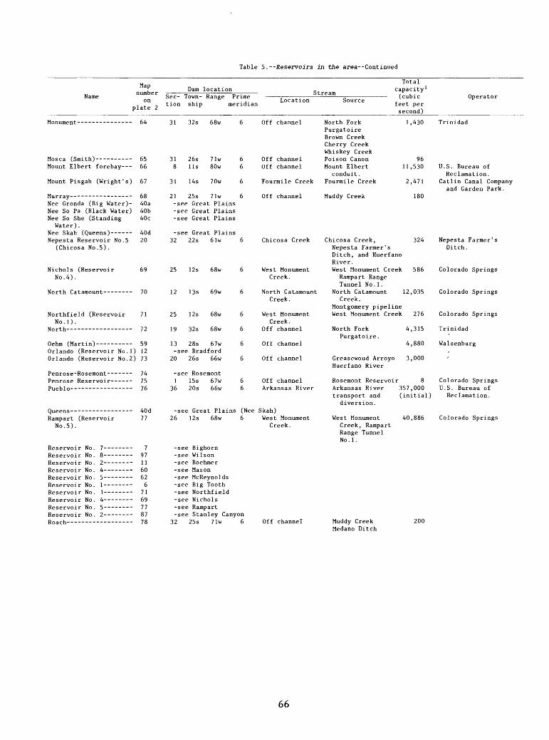
Table 5. --Reservoirs in the area Continued
Map, T number Name
onplate 2
Mount Elbert forebay---
Mount Pisgah (Wright's)
Nee Gronda (Big Water)- Nee So Pa (Black Water) Nee So She (Standing
Water) .
Nepesta Reservoir No. 5 (Chicosa No. 5) .
Nichols (Reservoir No. 4).
Northfield (Reservoir No . 1 ) .
North
Orlando (Reservoir No.l) Orlando (Reservoir No. 2)
Penrose Reservoir------
Rampart (Reservoir No. 5).
64
65 66
67
68 40a 40b 40c
40d 20
69
70
71
72
59 12 73
74 75 76
40d 77
7 97 11 60 62 6
71 69 77 877R
Dam locationSec- Town- Range Prime tion ship meridiar
31 32s 68w 6
31 26s 71w 6 8 11s 80w 6
31 14s 70w 6
21 25s 71w 6 -see Great Plains -see Great Plains -see Great Plains
-see Great Plains 32 22s 61w 6
25 12s 68w 6
12 13s 69w 6
25 12s 68w 6
19 32s 68w 6
13 28s 67w 6 -see Bradford
20 26s 66w 6
-see Rosemont 1 15s 67w 6
36 20s 66w 6
-see Great Plains (Nee 26 12s 68w 6
-see Bighorn -see Wilson -see Boehmer -see Mason -see McReynolds -see Big Tooth -see Northfield -see Nichols -see Rampart -see Stanley Canyon
T9 9=lc 71u f,
Location i
Off channel
Off channel Off channel
Fourmile Creek
Off channel
Chicosa Creek
West Monument Creek.
North Catamount Creek.
West Monument Creek.
Off channel
Off channel
Off channel
Off channel Arkansas River
Skah) West Monument
Creek.
Totalcapacity 1
ream , , .Source ,.
feet persecond)
North Fork 1,430 Purgatoire Brown Creek Cherry Creek Whiskey Creek Poison Canon 96 Mount Elbert 11,530
conduit. Fourmile Creek 2,471
Muddy Creek 180
Chicosa Creek, 324 Nepesta Farmer's Ditch, and Huerfano River. West Monument Creek 586
Rampart Range Tunnel No.l.
North Catamount 12,035 Creek.
Montgomery pipeline West Monument Creek 276
North Fork 4,315 Purgatoire.
4,880
Greasewoud Arroyo 3,000 Huerfano River
Rosemont Reservoir 8 Arkansas River 357,000 transport and (initial)
diversion.
West Monument 40,886 Creek, Rampart Range Tunnel No.l.
Miidrfu Opplc ?00
Operator
Trinidad
U.S. Bureau of Reclamation.
Catlin Canal Company and Garden Park.
Nepesta Farmer's Ditch.
Colorado Springs
Colorado Springs
Colorado Springs
Trinidad
Walsenburg
Colorado Springs U.S. Bureau of
Reclamation.
Colorado Springs
Medano Ditch
66

Table 5. --Reservoirs in the area--Continued
Map,, number Name
onplate 2
Dam locationSec- Town- Range Prime tion ship meridi<
Q)-O L
Location m
reamSource ,
Rosemont (Penrose-Rosemont) .
Ruedi 2 ---- -
Russell- ---------------
Saint Charles No. 2 -Saint Charles No. 3 ----Saliba (Antonio D.
Valdez).Seven Lakes------------Sharps Orchard---------Skagway-- --------------
Smith --South Catamount--------
South Suburban---------
Spinney Mountain2 ------Stanley Canyon (Reservoir No. 2) .
Sugar Loaf----- ------Sunnyside----- - - Teller Thurston- Timber Trinidad
Turquoise Lake (SugarLoaf).
Twin Lakes-------------
Two Buttes - -
Upper Blue 2 ---------- --
Verhoeff ------------- Vertrees---------------Victor No. 2 -
Wahatoya--- ------------
Walsenburg- ------------Wilson (Reservoir No. 8)
Wolf-- --
Wright' s - --------------
74
79
80
16172
818283
6584
85
8687
888990914792
88
93
94
95
969798
99
100101
102
67
23 15s 68w
18 8s 84w
20 33s 68w
-see CF&I No. 2-see CF&I No. 3
22 28s 65w
10 30s 62w1 28s 66w6 16s 68w
-see Mosca12 13s 69w
35 14s 67w
25 12s 74w19 12s 67w
6
6
6
6
666
6
6
66
East BeaverCreek.
Fryingpan River
Off channel
Hezron Gulch
Off channelOff channelBeaver Creek
South CatamountCreek.
Off channel
South PlatteStanley Canyon
East Beaver CreekGould Creek viaRoberts Tunnel.
Fryingpan River
Middle Fork ofPurgatoire River,
Whiskey Creek
>
Santa Clara Creek
Apishapa RiverCucharas RiverBeaver Creek
South CatamountCreek.
Montgomery pipelineNorth and South
Cheyenne Creeks.Homestake pipelineStanley Canyon
Total rapacity 1 (cubic :eet persecond)
2,538
102,369
200
4,880
4,76684
3,078
2,605
231
54,500104
Operator
Colorado Springs
U.S. Bureau ofRecalmation.
Beaver Park and Stateof Colorado.
Colorado Springs
Colorado Springs
AuroraU.S. Air Force
Academy.-see Turquoise Lake7 30s 66w
31 18s 66w13 21s 47w-see Horse Creek
27 33s 64w
19 9s 80w
22 11s 80w
1 28s 46w
3 85s 78w
28 22s 49w15 23s 63w3 15s 69w
22 29s 68w
23 28s 67w24 14s 69w
32 25s 71w
-see Mount Pisgah
666
6
6
6
6
6
666
6
66
6
Turkey CreekOff channel
Purgatoire
Lake Fork
Lake Creek
Two Buttes
Blue River
Simpson ArroyoEast branch ofWest BeaverCreek.
Off channel
Off channelEast Fork West
Beaver Creek.Off channel
Santa Clara CreekTurkey CreekArkansas River
Purgatoire
Lake Fork andtransmountainimports.
Lake Creek andtransmountainimports .
Two Buttes
Blue River
Fort Lyon drainageHuerfano RiverEast branch ofWest Beaver Creek.
Cucharas RiverWahatoya Creek.
CucharasEast Fork West
Beaver Creek.Muddy CreekMedano Ditch
163900
8,262
114,500
129,432
140,339
40,918
2,120
230658259
274
430669
Fort CarsonFort Lyon Canal
U.S. Corps ofEngineers.
U.S. Bureau ofReclamation.
U.S. Bureau ofRecalmation.
Two Buttes WaterAssociation.
Blue River ProjectColorado Springs
Victor
Walsenburg
WalsenburgColorado Springs
1 Reservoir capacities were 2Reservoir located outside
gathered from a number of the Arkansas River basin.
sources and are meant only to give an indication of relative size.
67