
Description of the RLC protocol - 3GPP
44
TSG-RAN #2 TSGR#2(99)147 Fort Lauderdale, USA, 2 nd to 4 th March 1999 Agenda Item: 6.2 Source: TSG RAN WG2 Title: S2.22 : RLC protocol specification Document for: Information ___________________________________________________________________________ Description of the RLC protocol
Transcript of Description of the RLC protocol - 3GPP

TSG-RAN #2 TSGR#2(99)147Fort Lauderdale, USA, 2nd to 4th March 1999
Agenda Item: 6.2
Source: TSG RAN WG2
Title: S2.22 : RLC protocol specification
Document for: Information
___________________________________________________________________________
Description of the RLC protocol

UMTS YY.22 V0.0. 6 1999 2
Referencexxxx
KeywordsDigital cellular telecommunications system,
Universal Mobile Telecommunication System(UMTS), UTRAN, IMT2000
ETSI/3GPP Secretariat
Postal addressF-06921 Sophia Antipolis Cedex - FRANCE
Office address650 Route des Lucioles - Sophia Antipolis
Valbonne - FRANCETel.: +33 4 92 94 42 00 Fax: +33 4 93 65 47 16
Siret N° 348 623 562 00017 - NAF 742 CAssociation à but non lucratif enregistrée à laSous-Préfecture de Grasse (06) N° 7803/88
X.400c= fr; a=atlas; p=etsi; s=secretariat
[email protected]://www.etsi.fr
Copyright Notification
Reproduction is only permitted for the purpose of standardization work undertaken within ETSI.The copyright and the foregoing restrictions extend to reproduction in all media.
© European Telecommunications Standards Institute 1998.All rights reserved.
UMTS YY.22 V0.0. 6 1999 3
Contents
1. SCOPE....................................................................................................................................................................... 4
2. REFERENCES.......................................................................................................................................................... 4
3. DEFINITIONS AND ABBREVIATIONS .............................................................................................................. 5
4. GENERAL................................................................................................................................................................. 6
4.1. OBJECTIVE................................................................................................................................................................ 64.2. OVERVIEW ON SUBLAYER ARCHITECTURE ................................................................................................................ 6
4.2.1. Model of RLC.............................................................................................................................................. 64.2.1.1. Model of transmitting side ...................................................................................................................................84.2.1.2. Model of receiving side........................................................................................................................................9
5. FUNCTIONS........................................................................................................................................................... 10
6. SERVICES PROVIDED TO UPPER LAYERS .................................................................................................. 10
7. SERVICES EXPECTED FROM MAC ................................................................................................................ 14
8. ELEMENTS FOR LAYER-TO-LAYER COMMUNICATION ........................................................................ 14
8.1. PRIMITIVES BETWEEN RLC AND HIGHER LAYERS ................................................................................................... 14
9. ELEMENTS FOR PEER-TO-PEER COMMUNICATION............................................................................... 14
9.1. PROTOCOL DATA UNITS........................................................................................................................................... 159.2. FORMATS AND PARAMETERS .................................................................................................................................. 159.3. PROTOCOL STATES.................................................................................................................................................. 209.4. STATE VARIABLES................................................................................................................................................... 209.5. TIMERS ................................................................................................................................................................... 219.6. PROTOCOL PARAMETERS........................................................................................................................................ 229.7. SPECIFIC FUNCTIONS ............................................................................................................................................... 22
9.7.1. Credit and peer-to-peer flow control ........................................................................................................ 22
10. HANDLING OF UNKNOWN, UNFORESEEN AND ERRONEOUS PROTOCOL DATA....................... 23
11. ELEMENTARY PROCEDURES...................................................................................................................... 23
12. SDL DIAGRAMS................................................................................................................................................ 23
13. 12. HISTORY...................................................................................................................................................... 44
14. .......................................................................................................................ERROR! BOOKMARK NOT DEFINED.

UMTS YY.22 V0.0. 6 1999 4
Intellectual Property RightsIPRs essential or potentially essential to the present deliverable may have been declared to ETSI/3GPP. The informationpertaining to these essential IPRs, if any, is publicly available for ETSI members and non-members, free of charge. Thiscan be found in the latest version of the ETSI Technical Report: ETR 314: "Intellectual Property Rights (IPRs);Essential or potentially Essential, IPRs notified to ETSI in respect of ETSI standards". The most recent update of ETR314, is available on the ETSI web server or on request from the Secretariat.Pursuant to the ETSI Interim IPR Policy, no investigation, including IPR searches, has been carried out by ETSI. Noguarantee can be given as to the existence of other IPRs not referenced in the ETR 314, which are, or may be, or maybecome, essential to the present document.
ForewordThis Technical Specification (TS) has been produced by the 3rd Generation Partnership Project (3GPP).The contents of this TS are subject to continuing work within 3GPP TSG-RAN and may change following formal TSGRAN approval.
1. ScopeThe scope of this description is to describe the RLC protocol. A description document is intermediate between a stage 2document and a protocol specification. Once completed, it should be sufficient for manufacturers to start some “ highlevel design ” activities. It should allow as well to assess the complexity of the associated protocol. After the completionof a description document, the drafting of the protocol specification should not have to face difficulties which wouldimpact the other protocols i.e. the radio interface protocol architecture should be stable. This means that someprocedures which are felt critical in terms of complexity will need to be studied in more details in the descriptiondocument so that no problem is faced in the writing of the final protocol.
The following lists typical contents for a description document :1. list of procedures2. logical flow diagrams for normal procedures3. logical description of message (where it should be possible to guess roughly the size of the various information
elements)4. principles for error handling5. some exceptional procedures which are felt critica6. It should, as far as possible, have the same format and outline as the final specification
The following is not covered1. exact message format2. all scenarios
2. References[1] UMTS XX.XX, UTRAN Architecture description;[2] Vocabulary used in the UMTS L2&L3 Expert Group;[3] [3] S2.01, Radio Interface Protocol Architecture Ver. 0.0.1[4] [4] S2.02, Layer 1; General requirements, Ver. 0.0.1[5] [5] S2.03, Description of UE States and Procedures in Connected Mode, Ver. 0.0.1[6] [6] s2.04 , UE Procedures in Idle Mode[7] [7] S2.21, Description of the MAC Protocol, Ver. 0.0.1[8] [8] S2.31b, Description of the RRC Protocol, Ver. 0.0.1

UMTS YY.22 V0.0. 6 1999 5
3. Definitions and Abbreviations
ARQ Automatic Repeat RequestBCCH Broadcast Control ChannelBCH Broadcast ChannelC- Control-CC Call ControlCCCH Common Control ChannelCCH Control ChannelCCTrCH Coded Composite Transport ChannelCN Core NetworkCRC Cyclic Redundancy CheckDC Dedicated Control (SAP)DCCH Dedicated Control ChannelDCH Dedicated ChannelDL DownlinkDSCH Downlink Shared ChannelDTCH Dedicated Traffic ChannelFACH Forward Link Access ChannelFCS Frame Check SequenceFDD Frequency Division DuplexGC General Control (SAP)HO HandoverITU International Telecommunication Unionkbps kilo-bits per secondL1 Layer 1 (physical layer)L2 Layer 2 (data link layer)L3 Layer 3 (network layer)MAC Medium Access ControlMS Mobile StationMM Mobility ManagementNt Notification (SAP)PCCH Paging Control ChannelPCH Paging ChannelPDU Protocol Data UnitPHY Physical layerPhyCH Physical ChannelsRACH Random Access ChannelRLC Radio Link ControlRNTI Radio Network Temporary IdentityRRC Radio Resource ControlSAP Service Access PointSCCH Synchronization Control ChannelSCH Synchronization ChannelSDU Service Data UnitTCH Traffic ChannelTDD Time Division DuplexTFI Transport Format IndicatorTFCI Transport Format Combination IndicatorTPC Transmit Power ControlU- User-UE User EquipmentUL UplinkUMTS Universal Mobile Telecommunications SystemURA UTRAN Registration AreaUTRA UMTS Terrestrial Radio AccessUTRAN UMTS Terrestrial Radio Access Network

UMTS YY.22 V0.0. 6 1999 6
4. General
4.1. Objective
4.2. Overview on sublayer architecture
4.2.1.Model of RLC
Figure 1 gives an overview model of the RLC layer. The figure illustrates two peer entities, one in the UE and one in theUTRAN. Though it is not shown in the figure the RLC layer may consist of several entities. A RLC entity offers threekinds of data transfer services to the higher layers. The services are transparent mode, unacknowledged mode andacknowledged mode data transfer. The entities have one transmitting side and one receiving side. More detailed7descriptions of the transmitting and receiving sides are given in subsections 4.2.1 and 4.2.2.

UMTS YY.22 V0.0. 6 1999 7
Una
ck.
func
tions
Ack
.fu
nctio
ns
MU
XD
EM
UX
Ack
.fu
nctio
nsU
nack
.fu
nctio
nsT
rans
p.fu
nctio
nsT
rans
p.fu
nctio
nsR
LC
Ctr
lU
nit
Una
ck.
func
tions
Ack
.fu
nctio
ns
MU
XD
EM
UX
Ack
.fu
nctio
nsU
nack
.fu
nctio
nsT
rans
p.fu
nctio
nsT
rans
p.fu
nctio
nsR
LC
Ctr
lU
nit
Tra
nsm
itti
ng s
ide
UT
RA
N
Rec
eivi
ng s
ide
Tra
nsm
itti
ng s
ide
Rec
eivi
ng s
ide
MS
Rad
io I
nter
face
RLC MACHigher layer
Figure Error! Style not defined.-Error! Bookmark not defined.. Overview model of RLC.

UMTS YY.22 V0.0. 6 1999 8
4.2.1.1. Model of transmitting side
A model of the transmitting side of a RLC entity is presented in Error! Reference source not found. below.
Transmissionbuffer
Transmissionbuffer
Segmentation &Concatenation &Set RLC Header
Segmentation
Transparent mode
Tr-SAP
Retransmissionbuffer &
mangement
MUX
Complete RLCHeader (eg poll bits)
MUX/Logical channel Selection (FFS)
Transmissionbuffer
RLC ControlUnit
Unacknowledged mode Acknowledged mode
Receivedacknowledgements
Acknowledgements
From receiving side
UM/AM-SAP
BCCH/PCCH/CCCH/DTCH
DCCHor
DTCH
DCCHor
DTCH
DCCHor
DTCH
Segmentation &Concatenation &Set RLC Header
Figure Error! Style not defined.-Error! Bookmark not defined.. The transmitting side of a RLC entity.
RLC offers three kinds of data transfer services to the higher layers through the RLC-SAP. The services are transparentmode, unacknowledged mode and acknowledged mode data transfer. The transparent mode is independent from bothunacknowledged mode data transfer and acknowledged mode data transfer. The independence between unacknowledgedmode and acknowledged mode is FFS. If the logical channel is a DCCH then there is only one DCCH. The dashed lineillustrates the possibility to transfer higher layer data during the establishment of an RLC link [Note: This could beuseful in the control plane but it is for further study]. A RLC entity can provide unacknowledged and acknowledgedmode data transfer simultaneously, but not transparent mode data transfer. Therefore are these services provided throughdifferent SAPs, Tr-SAP and UM/AM-SAP. The data flow through the transmitting side of an RLC entity for theseservices are described below.1. Transparent mode data transfer
RLC receives SDUs from the higher layers. RLC might segment the SDUs into appropriate RLC PDUs withoutadding any overhead. How to perform the segmentation is decided upon when the service is established. RLC
UMTS YY.22 V0.0. 6 1999 9
delivers the RLC PDUs to MAC through either a BCCH, PCCH or a DTCH. The delivery of RLC PDUs to MACthrough CCCH is FFS. Which type of logical channel depends on if the higher layer is located in the control plane(BCCH, PCCH, CCCH) or user plane (DTCH).
2. Unacknowledged mode data transferRLC receives SDUs from the higher layers. If the SDU is too large it is segmented into appropriate RLC PDUs. TheSDU might also be concatenated with other SDUs. RLC adds a header and the PDU is placed in the transmissionbuffer. The MUX then decides which PDUs and when the PDUs are delivered to MAC. The MUX also decideswhich logical channel that should be used. The number of logical channels that is needed is decided upon when theservice is established (e.g. in the figure there is three logical channels). The type of the logical channels depends onif the higher layer is located in the control plane (DCCH) or in the user plane (DTCH).
3. Acknowledged mode data transferRLC receives SDUs from the higher layers. The SDUs are segmented and/or concatenated to PDUs of fixed length.The length of the PDUs is decided upon when the service is established. After that RLC adds a header and the PDUis placed in the retransmission buffer and the transmission buffer. The MUX then decides which PDUs and whenthe PDUs are delivered to MAC, e.g. it could be useful to send RLC control PDUs on one logical channel and dataPDUs on another logical channel. The PDUs are delivered to the MUX via a function that sets the poll bit in thePDUs.The retransmission buffer also receives acknowledgements from the receiving side, which are used to indicateretransmissions of PDUs and when to delete a PDU from the retransmission buffer.
The RLC control unit controls the RLC entity and handles control signalling between the peer entities (e.g.establishment and release of a RLC link). It is split between the transmitting and receiving side.
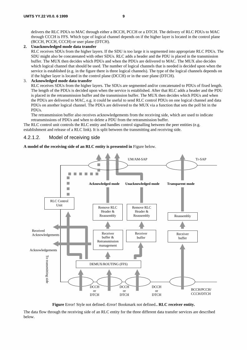
4.2.1.2. Model of receiving side
A model of the receiving side of an RLC entity is presented in Figure below.
Receiverbuffer
Remove RLCHeader &
Reassembly Reassembly
Unacknowledged mode
RLC ControlUnit
BCCH/PCCH/CCCH/DTCH
DEMUX/ROUTING (FFS)
Receiverbuffer &
Retransmissionmanagement
Acknowledgements
ReceivedAcknowledgements
Remove RLCHeader &
Reassembly
Receiverbuffer
Tr-SAPUM/AM-SAP
Acknowledged mode Transparent mode
To transm
itting side
DCCHor
DTCH
DCCHor
DTCH
DCCHor
DTCH
Figure Error! Style not defined.-Error! Bookmark not defined.. RLC receiver entity.
The data flow through the receiving side of an RLC entity for the three different data transfer services are describedbelow.

UMTS YY.22 V0.0. 6 1999 10
1. Transparent mode data transferRLC receives PDUs through either a DCCH or a DTCH from the MAC sublayer. RLC reassembles (if segmentationhas been performed) the PDUs into RLC SDUs. How to perform the reassembling is decided upon when the serviceis established. RLC delivers the RLC SDUs to the higher layer through the RLC-SAP.
2. Unacknowledged mode data transferRLC receives PDUs through one of the logical channels from the MAC sublayer. RLC removes header from thePDUs and reassembles the PDUs (if segmentation has been performed) into RLC SDUs. After that the SDUs aredelivered to the higher layer.
3. Acknowledged mode data transferRLC receives PDUs through one of the logical channels from the MAC sublayer. The PDUs are placed in thereceiver buffer until a complete SDU has been received. The receiver buffer requests retransmissions of PDUs bysending negative acknowledgements to the peer entity. After that the headers are removed from the PDUs and thePDUs are reassembled into a SDU. Finally the SDU is delivered to the higher layer.
The receiving side also receives acknowledgements from the peer entity. The acknowledgements are passed to theretransmission buffer on the transmitting side.The RLC control unit controls the RLC entity and handles control signalling between the peer entities (e.g.establishment and release of a RLC link). It is split between the transmitting and receiving side.
5. FunctionsFor a detailed description of the following functions see [3].
• Connection Control;
• Segmentation and reassembly;
• Concatenation;
• Padding;
• Transfer of user data;
• Error correction;
• In-sequence delivery of higher layer PDUs;
• Duplicate Detection;
• Flow control;
• Protocol error detection and recovery.
The following potential function(s) are regarded as further study items:
• Suspend/resume function;
• Ciphering.
• Quick repeat (FFS).
6. Services provided to upper layers For a detailed description of the following functions see [3].
• • RLC connection establishment/release;
• • Transparent data transfer ServiceFollowing functions are needed to support transparent data transfer:
• Segmentation and reassembly

UMTS YY.22 V0.0. 6 1999 11
• Transfer of user data;
• • Unacknowledged data transfer ServiceFollowing functions are needed to support unacknowledged data transfer:
• Segmentation and reassembly
• Concatenation
• Transfer of user data;
• • Acknowledged data transfer ServiceFollowing functions are needed to support acknowledged data transfer:
• Segmentation and reassembly
• Concatenation
• Transfer of user data
• Error correction
• In-sequence delivery of higher layer PDUs
• Duplicate detection
• Flow Control
• Protocol error detection and recovery;
• QoS setting;
• Notification of unrecoverable errors.
• Multicast delivery of higher layer messages. (FFS)

UMTS YY.22 V0.0. 6 1999 12
Table Error! Style not defined.-Error! Bookmark not defined.: RLC modes and functions in UE downlink side
Service Functions CCCH DCCH DTCH
Transparent
Service
Applicability + - +
Segmentation - - +
Unacknowledged
Service
Applicability FFS + +
Segmentation - + +
Concatenation - + +
Acknowledged
Service
Applicability - + +
Segmentation - + +
Concatenation - + +
Flow Control - + +
Error Correction - + +
Protocol errorcorrection & recovery
- + +
.
Table Error! Style not defined.-Error! Bookmark not defined.: RLC modes and functions in UE uplink side
Service Functions SCCH BCCH PCCH CCCH DCCH DTCH
Transparent
Service
Applicability + + + + - +
Reassembly + + + - - +
Unacknowledged
Service
Applicability + + + FFS + +
Reassembly + + + - + +
Acknowledged
Service
Applicability - - - - + +
Reassembly - - - - + +
Error correction - - - - + +
Flow Control - - - - + +
In sequence delivery - - - - + +
Duplicate detection - - - - + +
Protocol errorcorrection & recovery
- - - - + +

UMTS YY.22 V0.0. 6 1999 13
Table 3.
Table Error! Style not defined.-Error! Bookmark not defined.: RLC modes and functions in UTRAN downlink side
Service Functions SCCH BCCH PCCH CCCH DCCH DTCH
Transparent
Service
Applicability + + + + - +
Segmentation + + + - - +
Unacknowledged
Service
Applicability + + + FFS + +
Segmentation + + + - + +
Concatenation + + + - + +
Acknowledged
Service
Applicability - - - - + +
Segmentation - - - - + +
Concatenation - - - - + +
Flow Control - - - - + +
Error Correction - - - - + +
Protocol errorcorrection & recovery
- - - - + +
Table Error! Style not defined.-Error! Bookmark not defined.: RLC modes and functions in UTRAN uplink side
Service Functions CCCH DCCH DTCH
Transparent
Service
Applicability + - +
Reassembly - - +
Unacknowledged
Service
Applicability FFS + +
Reassembly - + +
Acknowledged
Service
Applicability - + +
Reassembly - + +
Error correction - + +
Flow Control - + +
In sequence delivery - + +
Duplicate detection - + +
Protocol errorcorrection & recovery
- + +

UMTS YY.22 V0.0. 6 1999 14
7. Services expected from MACFor a detailed description of the following functions see [3].• Data transfer;
• Acknowledged data transfer service by MAC for transmission on RACH/FACH is FFS.
8. Elements for layer-to-layer communication
8.1.Primitives between RLC and higher layersThe primitives between RLC and upper layers are shown in Table 8.1-1.
Table Error! Style not defined.-Error! Bookmark not defined. : Primitives between RLC and upper layers
Generic Name ParameterReq. ind. Resp. conf.
RLC-AM-DATA MU MU Not Defined Not DefinedRLC-UM-DATA MU, QR (ffs) MU Not Defined Not DefinedRLC-TR-DATA MU MU Not Defined Not DefinedMRLC-CONFIGUREMRLC RELEASE Not Defined Not Defined
Each Primitive is defined as follows:a) RLC-AM-DATA req./ind.
It is used for acknowledged data transmission mode of point-to-point connection between the same level user entities.
[Editor’s note: Confirmation for the RLC-AM-DATA procedure is FFS.]
b) RLC-UM-DATA req./ind.It is used for unacknowledged data transmission mode of point-to-point connection between the same level userentities.
c) RLC-TR-DATA req./indIt is used for trasparent data transmission mode of point-to-point connection between the same level user entities.
d) MRLC-CONFIGUREFFS
e) MRLC RELEASEFFS
The parameter Message Unit (MU) is mapped on MU field on RLC PDU transparently in the case of RLC-AM-DATAreq. or RLC-UM-DATA req. And the MU field of RLC PDU received is mapped on MU in the case of RLC-AM-DATA ind. or RLC-UM-DATA ind. transparently. Length of MU must be n octets (n is integer).The Quick Repeat indicator (QR) indicates whether UMD PDU will be transmitted with Quick Repeat or not. It holdsone of two values: “Yes” or “No”. (The need of this indicator is FFS)
9. Elements for peer-to-peer communicationIn unacknowledged transmission, only one type of unacknowledged data PDU is exchanged between peer RLC entitiesIn acknowledged transmission, both (acknowledged) data PDUs and control PDUs are exchanged between peer RLCentities.

UMTS YY.22 V0.0. 6 1999 15
9.1.Protocol data units
Data PDU
a) AMD PDU (Acknowledged Mode Data PDU)The AMD PDU is used to convey sequentially numbered PDUs containing RLC SDU data. The AMD PDU isused by the RLC when it is in the acknowledged mode.
b) UMD PDU (Unacknowledged Mode Data PDU)The UMD PDU is used to convey sequentially numbered PDUs containing RLC SDU data. It is used by the RLCwhen using the unacknowledged data transfer.
Control PDU
a) BGN PDU (Begin)The BGN PDU is used by a RLC entity in order to establish a RLC link between the entity and its peer entity.
b) BGAK PDU (Begin Acknowledge)
The BGAK PDU is an acknowledgement to the BGN PDU.
c) BGREJ PDU (Begin Reject)
The BGREJ PDU is used to reject the RLC link setup request of the peer RLC entity.
d) END PDU (End)
The END PDU is used by a RLC entity in order to release the RLC link between the entity and its peer entity.
e) ENDAK PDU (End Acknowledge)
The ENDAK PDU is an acknowledgement to the END PDU.
f) STAT PDU (Solicited Status Response) (FFS)The STAT PDU is used to respond to a status request from the peer RLC entity.
g) USTAT PDU (Unsolicited Status Response) (FFS)The USTAT PDU is transmitted upon detection of an erroneous transmission of one or more data PDUs. It is used toinform the transmitter side about missing AMD PDUs at the receiver RLC.
Table Error! Style not defined.-Error! Bookmark not defined. : RLC PDU names and descriptions
Functionality PDU name Description
Establishment BGN Request Initialization
BGAK Request Acknowledgement
BGREJ Connection Reject
Release END Disconnect Command
ENDAK Disconnect Acknowledgement
Acknowledged Data Transfer AMD Sequenced acknowledged mode data
STAT Solicited Status Report
USTAT Unsolicited Status Report
Unacknowledged Data Transfer UMD Sequenced unacknowledged mode data
9.2.Formats and parameters
[All the section shall be reviewed when the protocol is defined]

UMTS YY.22 V0.0. 6 1999 16
AMD PDUNote: R bit may be H bit. It is FFS.

UMTS YY.22 V0.0. 6 1999 17
Sequence Number
Sequence Number
A/U
E
ELength Indicator
Data
PAD
Oct‚P
Oct‚Q
Oct‚R
OctN
P
(Optional)
R
Figure Error! Style not defined.-Error! Bookmark not defined.. AMD PDU
UMD PDU
Oct‚P
Oct‚Q
OctN
Sequence Number E
ELength Indicator
Data
PAD
A/U
(Optional)
Figure Error! Style not defined.-Error! Bookmark not defined.. UMD PDU
BGN PDU
Oct‚P
Oct‚Q
Oct‚R
OctN
A/U N(SQ)PDU Type
PAD
N(MR)
N(MR) Reserved
Figure Error! Style not defined.-Error! Bookmark not defined.. BGN PDU
BGAK PDU
Oct‚P
Oct‚Q
Oct‚R
OctN
A/U RPDU Type
PAD
N(MR)
N(MR) Reserved
Figure Error! Style not defined.-Error! Bookmark not defined.. BGAK PDU
BGREJ, END, ENDAK PDU

UMTS YY.22 V0.0. 6 1999 18
Oct‚P
OctN
A/U RPDU Type
PAD
Figure Error! Style not defined.-Error! Bookmark not defined.. BGREJ, END, ENDAK PDU
STAT PDU
Oct‚P
Oct‚Q
Oct‚R
OctN
A/U RPDU Type
List Elements
N(R)
N(MR)N(R) N(MR)
Oct4
Number of List Elements R Oct5
PAD
Figure Error! Style not defined.-Error! Bookmark not defined.. STAT PDU
USTAT PDU
Oct‚P
Oct‚Q
Oct‚R
OctN
A/U RPDU Type
List Element 1
N(R)
N(MR)N(R) N(MR)
Oct4
List Element 2
List Element 1 List Element 2
Oct5
Oct6
Oct7
PAD
Figure Error! Style not defined.-Error! Bookmark not defined.. USTAT PDU
Note: Regarding STAT and USTAT, it is FFS. whether a bitmap type of PDU status indication would be more efficientthan List elements.
The RLC PDU parameters are defined as follows:
• A/U bit: 1bitThis field indicates Acknowledged mode data PDU or Unacknowledged mode data PDU/ Control PDU. If itindicates Acknowledged mode, the PDU is AMD PDU.
Bit Description
0 Unacknowledged mode data PDU/ Control PDU1 Acknowledged mode data PDU
• PDU Type: 6bitThis field indicates the type of Control PDU. They are indicated by the special values of sequence number field.

UMTS YY.22 V0.0. 6 1999 19
Bit PDU Type Bit PDU Type
111111 BGN 111010 STAT111110 BGAK 111001 USTAT111101 BGREJ 111000 –
110000Reserved
111100 END111011 ENDAK
• Sequence Number (SN)This field indicates the sequence number of the RLC PDU.
PDU type Length Notes
AMD PDU 12 bit Used for retransmission and reassembly
UMD PDU 6 bit Used for reassemblyEspecially “110000” – “111111” are reserved forPDU Type (Control PDU)
• Polling bit (P): 1bitThis field is used to request a status report (STAT PDU) from the receiver RLC.
Bit Description
0 -1 Request a status report
• Extension bit (E): 1bitThis bit indicates whether the next octet will be header information (LI) or data.
Bit Description
0 The next octet is data1 The next octet is header information (LI)
• Reserved (R):One function of this field is to achieve octet alignment. Other functions are FFS. Where no functions are defined,this field shall be coded as zero. This field ignored by the receiver.
• Length Indicator (LI): 7bitThis field is optional and is used if concatenation or padding takes pRLCe. It indicates the end of the last segmentof a SDU. Especially “0000000” indicates that the previous RLC PDU is exactly filled with the last segment of aRLC SDU, and “1111111” indicates that the rest part of the RLC PDU is padding.
• N(SQ): 1bitThis field carries the connection sequence value. VT(SQ) is mapped to N(SQ) whenever a new BGN PDU istransmitted. This field is used by the receiver together with VR(SQ) to identify retransmitted BGN PDU.
• N(R): 12bitVR(R) is mapped to N(R) whenever a STAT or USTAT PDU is generated.
• N(MR): 12bitVR(MR) is mapped to N(R) whenever a STAT, USTAT, BGN, or BGAK PDU is generated. This is the basis forcredit granting by the receiver.
• Number of List Elements: 7bitIt indicates the number of list elements that included in the STAT PDU.
• Header extension flag (H): 1bit

UMTS YY.22 V0.0. 6 1999 20
This header extension flag indicates that there is an additional control part (SN+H+E) in an acknowledged modeRLC PDU header. The use of this flag is FFS
• Data:In this field data from higher layer PDUs is mapped.
9.3.Protocol states
This sub-section describes the states of a RLC entity. These states are used in the specification of the peer-to-peerprotocol. The states are conceptual and reflect general conditions of the RLC entity in the sequences of signals and PDUexchanges with its user and peer, respectively. In addition, other conditions are used in the description, in order to avoididentification of additional states, as detailed in the SDLs. The basic states are:
– State 1 – IdleEach RLC entity is conceptually initiated in the Idle state (State 1) and returns to this state upon the release of aconnection.
– State 2 – Outgoing Connection PendingA RLC entity requesting a connection with its peer is in the Outgoing Connection Pending state (State 2) until it receivesacknowledgment from its peer.
– State 3 – Incoming Connection PendingA RLC entity that has received a connection request from its peer and is waiting for its user’s response is in theIncoming Connection Pending (State 3).
– State 4 – Outgoing Disconnection PendingA RLC entity requesting release of the peer-to-peer connection goes to the Outgoing Disconnection Pending state (State4) until it receives confirmation that the peer entity has released and transited to the Idle state (State 1), after which itdoes the same.
– State 5 – Data Transfer ReadyUpon successful completion of the connection establishment procedures, both peer RLC entities will be in Data TransferReady state (State 5) and acknowledged data transfer can take place.
9.4.State variablesThis sub-clause describes the state variables used in the specification of the peer-to-peer protocol. AMD PDUs are
sequentially and independently numbered and may have the value 0 through n minus 1 (where n is the modulus of thesequence numbers). The modulus equals 212 and the sequence numbers cycle through the entire range, 0 through 212 –1. All arithmetic operations on the following state variables and sequence numbers contained in this Recommendationare affected by the modulus: VT(S), VT(A), VT(MS), VR(R), VR(H), and VR(MR). When performing arithmeticcomparisons of transmitter variables, VT(A) is assumed to be the base. When performing arithmetic comparisons ofreceiver variables, VR(R) is assumed to be the base. In addition, the state variables VT(SQ) and VR(SQ) use modulo 2arithmetic and VT(US) and VT(UR) use modulo 48. The RLC maintains the following state variables at the transmitter.
a) VT(S) - Send state variableThe sequence number of the next AMD to be transmitted for the first time (i.e. excluding retransmission). Incrementedafter transmission of a AMD for the first time (i.e. excluding retransmission).
b) VT(A) - Acknowledge state variableThe sequence number of the next in-sequence AMD PDU expected to be acknowledged, which forms the lower edge ofthe window of acceptable acknowledgments. VT(A) is updated upon acknowledgment of in-sequence AMD PDUs.
c) VT(DAT)This state variable is used to count the retransmission number of each AMD PDU. VT(DAT) is incremented by sendingAMD.

UMTS YY.22 V0.0. 6 1999 21
d) VT(MS) - Maximum Send state variableThe sequence number of the first AMD PDU not allowed by the peer receiver [i.e. the receiver will allow up to VT(MS)– 1]. This value represents the upper edge of the transmit window. The transmitter shall not transmit a new AMD PDU ifVT(S) = VT(MS). VT(MS) is updated based on receipt of a USTAT PDU, STAT PDU, BGN PDU, BGAK PDU.
e) VT(CC) - Connection Control state variableThe number of unacknowledged BGN, END PDUs. VT(CC) is incremented upon transmission of a BGN, END PDU. Ifan END PDU is transmitted in response to a protocol error, RLC does not wait for an ENDAK PDU [i.e. RLC movesdirectly to state 1 (Idle)] and VT(CC) is not incremented.
f) VT(SQ) - Transmitter Connection Sequence state variableThis state variable is used to allow the receiver to identify retransmitted BGN PDUs. This state variable is initialized to0 upon creation of the RLC process and incremented and then mapped into the N(SQ) field before the initialtransmission of either a BGN PDU.
g) VT(US) - Unit data state variableThis state variable means new sequence number of UMD-PDU which will send next. After new UMD-PDU is sent,VT(US) will be incremented.
h) VT(QR) - Quick repeat state variable (FFS)This state variable is used to count the retransmission number when UMD-PDU is sent by quick repeat scheme. It isincremented after UMD-PDU is sent and quick repeat will be continued until VT(QR) becomes to equal MaxQR.
The RLC maintains the following state variables at the receiver:a) VR(R) - Receive state variableThe sequence number of the next in-sequence AMD PDU expected to be received. Incremented upon receipt of the nextin-sequence AMD PDU.
b) VR(H) - Highest expected state variableThe sequence number of the next highest expected AMD PDU. This state variable is updated whenever a new AMDPDU is received.
c) VR(MR) - Maximum acceptable Receive state variableThe sequence number of the first AMD PDU not allowed by the receiver [i.e. the receiver will allow up to VR(MR) –1]. The receiver shall discard AMD PDUs with N(S) = VR(MR), (in one case, such an AMD PDU may cause thetransmission of a USTAT). Updating VR(MR) is implementation dependent, but VR(MR) should not be set to a value <VR(H).
d) VR(SQ) - Receiver Connection Sequence state variableThis state variable is used to identify retransmitted BGN PDUs. Upon reception of a BGN PDU, this state variable iscompared to the value of N(SQ) and then assigned the value of N(SQ). If the values are different, the PDU is processedand VR(SQ) is set to N(SQ). If they are equal, the PDU is identified as a retransmission.
e) VR(US) - Receiver Send Sequence state variableThe sequence number of the latest UMD PDU to be received. It is used to check the duplication receive. When newUMD PDU is received, VR(US) is compared with N(US). If VR(US),N(US), this PDU is quashed because duplicationreceive happens. And if not, N(US) is substituted for VR(US).f) VR(EP) – Estimated PDU Counter state variable (FFS)The number of PDUs that should have been received after the latest USTAT was sent. In acknowledged mode, this statevariable is updated at the end of each transmission time interval. It is incremented by the number of PDUs that shouldhave been received during the transmission time interval. If VR(EP) is equal to the number of requested PDUs in thelatest USTAT, then check if all PDUs requested for retransmission have been received.
9.5.Timersa) Timer_STAT
It is used to detect the loss of the response from receiver side. This timer is set when transmitted AMD PDUrequests status report (i.e. P bit is set to “1”). And it will be stopped when the transmitter receive Acknowledgement

UMTS YY.22 V0.0. 6 1999 22
of the AMD PDU by STAT PDU or USTAT PDU. When this timer is over, the oldest unconfirmed AMD PDUshould be retransmitted with requesting status report, and this timer is set again.
b) Timer_ProhibitIt is used to prohibit transmission of polling message within a certain period. It prohibits only the polling of everyRLC SDU. For other polling trigger, even if this timer is active, polling message can be transmitted. This timer isset when AMD PDU with polling is transmitted. When this timer is over no action is performed. (T_STAT =<T_Prohibit)
c) Timer_CCTimer_CC protects the transmission of PDU between connection establishment and connection release, during re-synchronization or during error recovery. Timer_CC is indicates retransmission interval when confirmation isn’treceived against BGN PDU and ENDPDU. The value of Timer_CC should be a little larger than the round-tripdelay.
d) Timer_QR (FFS)Transmission interval of quick repeat for UMD PDU.
e) Timer_EPC (FFS)This timer accounts for the roundtrip delay, i.e. the time when the first retransmitted PDU should be received after aUSTAT/USTAT has been sent. The value of Timer_EPC is heavily based on the transmission time interval(corresponding to the Layer 1 interleaving depth). When changing the transmission time interval, then the value ofthe EPC timer also needs to be changed.
9.6.Protocol ParametersThe value of each RLC protocol parameter is application specific and may be defined in another Recommendationwhich references this Recommendation.
a) MaxCCMaximum value for the state variable VT(CC), corresponding to the maximum number of transmissions of a BGN,END.
b) MaxDATIt is Maximum value for the number of retransmission of AMD PDU. This parameter is an upper limit of counterVT(DAT). When the value of VT(DAT) comes to MaxDAT, error recovery procedure will be performed.
c) MaxQRMaximum successive transmission number of UMD PDU. This parameter is an upper limit for counter VT(QR).
d) MaxSTATMaximum number of list elements placed in a STAT PDU. When the number of list items exceeds MaxSTAT, theSTAT message shall be segmented. All of the PDUs carrying the segmented STAT message, except possibly the lastone, contain MaxSTAT list items. This parameter is not used by the receiver of a STAT PDU for length checking, but isonly used by the sender of the STAT message for segmentation purposes. This parameter should be an odd integergreater than or equal to 3.
e) CreditThis parameter is used to coordinate credit notifications to layer management. When RLC is blocked from transmitting anew AMD PDU due to insufficient credit, “Credit” is assigned the value “No”. When RLC is permitted to transmit anew AMD PDU, “Credit” is assigned the value of “Yes”. Credit is initially assigned “Yes”.
9.7.Specific functions[All the section shall be reviewed when the protocol is defined]
9.7.1.Credit and peer-to-peer flow control
Credit is granted by the RLC receiver to allow the peer RLC transmitter to transmit new AMD PDUs. The processby which a receiver entity determines credit is not subject to standardization, but is related to the buffer availability andthe bandwidth/delay of the connection.

UMTS YY.22 V0.0. 6 1999 23
Details of the usage of Crediting is FFS.
9.2 Local flow control RLC events, such as reception of PDUs and external and internal signals, are normally processed in the order inwhich they occurred. However, events pertaining to the exchange of RLC link status information have priority over datatransfer. An implementation may detect congestion (for example, a long queuing delay) in its lower protocol layers. If so, datatransfer should be temporarily suspended in order to give priority to connection control messages. The means by whichan RLC entity decides whether or not it is congested depends on the protocol environment, including protocol timervalues, and is not subject to standardization.
If a RLC entity detects local congestion (“lower layer busy” in the SDL specification), it can elect to suspend theservicing of RLC-AM-DATA.request, RLC-UM-DATA.request It can also suspend the retransmission of requestedAMD PDUs. The data transfer procedures allow this to occur without causing protocol errors. Therefore, in terms of transmitting PDUs to the peer receiver, all types of PDUs except AMD PDU and UMD PDUare given highest priority. The AMD PDUs and UMD PDUs have equal priority. Among the AMD PDUs,retransmission have priority over new transmission if both types are pending. These priorities are only internal to RLC.
10. Handling of unknown, unforeseen and erroneousprotocol data
11. Elementary procedures(Examples: idle, data transfer, RLC connection setup, RLC connection release, re-synchronisation)
12. SDL diagramsThe resultant SDL diagrams (Timer_Prohibit scheme) are followed is shown in ANNEX 1.Estimated PDU Counter (EPC) scheme (receiving side) (FFS)Send a status report (USTAT), requesting for the retransmission of K number of missing PDUs.Start Timer_EPC. This timer accounts for the roundtrip delay, i.e. the time when the first retransmitted PDU should bereceived.When the timer expires, start counting the received PDUs, or rather the PDUs that should have been received using thestate variable VT(EP)If VT(EP) = K, then check if all PDUs (requested in the status report in step 1) have been received.If some of the previously missing PDUs are still missing, then repeat the procedure from step 1 for the PDUs that arestill missing.If none of the previously missing PDUs are still missing, then no status report needs to be sent, unless a poll had beentransmitted or a new missing PDU has been detected. In case of a poll or a new missing PDU, then repeat the procedurefrom step 1.Every poll received during the time when the Timer_EPC is active and VT(EP) < K will be discarded by the receivingside, i.e. neither STATs nor USTATs will be sent from the receiving side during this time.

UMTS YY.22 V0.0. 6 1999 24
Clear Transmitter
BGN PDU
VT(SQ) := 0VT(US) := 1
Idle 1
VT(MS) := BGN.N(MR)
TRUE
FALSE
Set Timer_CC
Clear-buffers := BR
Outgoing ConnectionPending 2
Idle 1
Idle 1
Idle 1
VR(SQ) := 0VR(US) := 0Clear-buffers := Yes
VT(CC) := 1VT(SQ) := VT(SQ) + 1
Initialize VR(MR)
LAC-ESTABLISH.request
Incoming ConnectionPending 2
Detect Retransmission
BGN PDU
LAC-ESTABLISH.Indication
Retransmission
BGREJ PDU
BGREJ PDU END PDU
ENDAK PDU
Idle 1
ENDAK PDU
Figure Error! Style not defined.-Error! Bookmark not defined.
Idle 1
Idle 1
BGAK PDU STAT PDU USTAT PDU
END PDU
Idle 1
AMD PDU
AMD PDU queued up
Figure Error! Style not defined.-Error! Bookmark not defined.

UMTS YY.22 V0.0. 6 1999 25
Outgoing ConnectionPending 2
ENDAK PDU
STAT PDU
USTAT PDUAMD PDU
END PDU
Outgoing ConnectionPending 2
AMD PDU queued up
Figure Error! Style not defined.-Error! Bookmark not defined.
Reset Timer_CC
LAC-RELEASE.indication
TRUE
Reset Timer_CC
Idle 1
Initialize State Variables
Outgoing ConnectionPending 2
BGAK PDU BGREJ PDU
Outgoing ConnectionPending 2
VT(MS) := BGAK.N(MR)
LAC-ESTABLISH.confirm
Set Data Transfer Timers
Data Transfer Ready 5
FALSE
Retransmission
BGN PDU
Reset Timer_CC
VT(MS) := BGN.N(MR)
Initialize VR(MR)
BGAK PDU
LAC-ESTABLISH.confirm
Initialize State Variables
Set Data Transfer Timers
Data Transfer Ready 5
Detect Retransmission
TRUE
Figure Error! Style not defined.-Error! Bookmark not defined.

UMTS YY.22 V0.0. 6 1999 26
END PDU
TRUE
FALSE
Idle 1
Outgoing ConnectionPending 2
VT(CC) >= MaxCC
BGN PDU
Idle 1
Outgoing ConnectionPending 2
Timer_CC (expiry)
LAC-RELEASE.indication
MLAC-RELEASE.request
Reset Timer_CC
Set Timer_CC
VT(CC) := VT(CC) + 1
Reset Timer_CC
END PDU
Outgoing DisconnectionPending 4
Set Timer_CC
VT(CC) := 1
LAC-RELEASE.request
Figure Error! Style not defined.-Error! Bookmark not defined.
Clear Transmitter
Initialize State Variables
Incoming ConnectionPending 3
Incoming ConnectionPending 3
Clear-buffers := BR
Set Data Transfer Timers
Data Transfer Ready 5
FALSE
Retransmission
BGN PDU
VT(MS) := BGN.N(MR)
Initialize VR(MR)
BGAK PDU
Detect Retransmission
TRUE
LAC-RELEASE.indication
LAC-ESTABLISH.indication
Incoming ConnectionPending 3
END PDULAC-ESTABLISH.response
MLAC-RELEASE.request
Idle 1
Idle 1
ENDAK PDU
LAC-RELEASE.indication
Figure Error! Style not defined.-Error! Bookmark not defined.
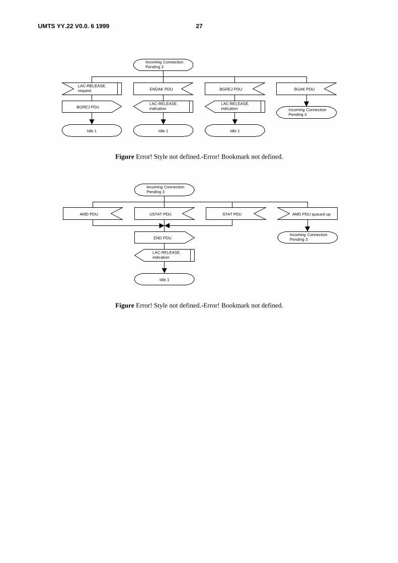
UMTS YY.22 V0.0. 6 1999 27
Incoming ConnectionPending 3
Incoming ConnectionPending 3
BGREJ PDU
LAC-RELEASE.indication
TRUEIdle 1
ENDAK PDU BGAK PDU
LAC-RELEASE.indication
TRUEIdle 1Idle 1
BGREJ PDU
LAC-RELEASE.request
Figure Error! Style not defined.-Error! Bookmark not defined.
Incoming ConnectionPending 3
Incoming ConnectionPending 3
AMD PDU
Idle 1
AMD PDU queued upUSTAT PDU STAT PDU
LAC-RELEASE.indication
END PDU
Figure Error! Style not defined.-Error! Bookmark not defined.

UMTS YY.22 V0.0. 6 1999 28
Clear Transmitter
Clear-buffers := BR
FALSE
Retransmission
BGN PDU
VT(MS) := BGN.N(MR)Initialize VR(MR)
BGN PDU
Detect Retransmission
TRUE
LAC-RELEASE.confirm
LAC-ESTABLISH.indication
Incoming ConnectionPending 3
LAC-ESTABLISH.request
Set Timer_CC
VT(CC) := 1VT(SQ) := VT(SQ) + 1
Reset Timer_CC
Outgoing ConnectionPending 2
Reset Timer_CC
Outgoing DisconnectionPending 4
Outgoing DisconnectionPending 4
END PDU
BGAK PDU
Outgoing DisconnectionPending 4
AMD PDU queued up
Figure Error! Style not defined.-Error! Bookmark not defined.
BGAK PDU
Outgoing DisconnectionPending 4
Outgoing DisconnectionPending 4
AMD PDU STAT PDU USTAT PDU
Figure Error! Style not defined.-Error! Bookmark not defined.

UMTS YY.22 V0.0. 6 1999 29
FALSE
Retransmission
Timer_CC (expiry)
ENDAK PDU
TRUE
LAC-RELEASE.confirm
Reset Timer_CC
VT(CC) := VT(CC) + 1
Outgoing DisconnectionPending 4
Outgoing DisconnectionPending 4
END PDU
END PDU
Idle 1
LAC-RELEASE.confirm
Reset Timer_CC
END PDU
Idle 1
BGREJ PDU
Idle 1
Set Timer_CC
LAC-RELEASE.confirm
Figure Error! Style not defined.-Error! Bookmark not defined.
Timer_STAT (expiry)
Data Transfer Ready 5
Put AMD PDU intoRetransmission queue withAMD.P := 1
AMD PDU queued up
Data Transfer Ready 5
Save AMD PDU inTransmission buffer
Remove AMD.N(S) = VT(A)from Transmission buffer
Idle 1
MLAC-RELEASE.request
Reset Data TransferTimers
Release buffers
LAC-AMDATA. request
AMD PDU queued up
Save AMD PDU inAM queue
TRUE
FALSE
n := 0
n := n + 1
n >= NP
Segmentation for AMD PDU
Data Transfer Ready 5
Figure Error! Style not defined.-Error! Bookmark not defined.

UMTS YY.22 V0.0. 6 1999 30
AMD PDU queued up
Retransmissionqueue is empty
AM queue is empty
Remove AMD PDU fromAM queue
AM queueis empty or VT(S) >=
VT(MS)
AMD.P := 1
AMD PDU
Set Timer_STATSet Timer_Prohibit
Timer_Prohibit is Active
AMD PDU
TRUE
TRUE
TRUE
FALSE
FALSE
FALSE
Save AMD PDU in Transmissionbuffer VT(DAT) := 0
TRUE
FALSE
Remove AMD PDU fromRetransmission queue
FALSE
TRUE
AMD.P = 1
AMD PDU
Save AMD PDU inTransmission buffer andSTAT_waiting bufferP := 0VT(DAT) := 0
AMD. VT(DAT) >= MaxDATTRUE
Update stored AMD PDU.VT(DAT) in Transmission bufferVT(DAT) := VT(DAT) + 1
TRUE
FALSE
Save AMD PDU inSTAT_waiting bufferP := 0VT(DAT) := VT(DAT) + 1
AMD PDU
FALSE
AAMD.P = 1
AMD.P := 0
Update stored AMD PDU.VT(DAT) in Transmission bufferP := 0VT(DAT) := VT(DAT) + 1
If another AMD PDU isalready in STAT_waitingbuffer, replace old AMDPDU with new AMD PDU.
Data Transfer Ready 5
Data Transfer Ready 5
Data Transfer Ready 5
Data Transfer Ready 5
Data Transfer Ready 5
Reset Data TransferTimers
VT(S) := VT(S) + 1
VT(S) := VT(S) + 1
Figure Error! Style not defined.-Error! Bookmark not defined.

UMTS YY.22 V0.0. 6 1999 31
VT(CC) := 1VT(SQ) := VT(SQ) + 1
A
BGN PDU
Set Timer_CC
Release buffers
Initialize VR(MR)
Outgoing ConnectionPending 2
Figure Error! Style not defined.-Error! Bookmark not defined.

UMTS YY.22 V0.0. 6 1999 32
Data Transfer Ready 5
FALSE
TRUE
AMD PDU
AMD PDU.P = 1
C
Receiver bufferis available
AMD.N(S) < VR(R)
AMD.N(S) = VR(H)
Save AMD PDU inReceiver buffer
VR(H) := VR(H) + 1
TRUE
TRUE
TRUE
FALSE
FALSE
C C
TRUE
FALSE
FALSE
TRUESave AMD PDU inReceiver buffer
Save AMD PDU inReceiver bufferVR(H) := AMD.N(S) + 1
VR(H) < AMD.N(S)
AMD.N(S)is already in
Receiver buffer
AMD.N(S) < VR(MR)
AMD.N(S) = VR(R)
TRUE
TRUE
C
TRUE
FALSE
VR(H) := VR(MR)
VR(H) < VR(MR)
FALSE
FALSE
Data Transfer Ready 5
FALSE
Remove AMD PDU withAMD.N(S) = VR(R) fromReceiver buffer
Save AMD PDU inAM_Reassembly buffer
AMD.N(S) = VR(H)
AMD.N(S) =VR(R) is in
Receiver buffer
TRUE
Save AMD PDU inAM_Reassembly buffer
VR(R) := VR(R) + 1
C
FALSE
FALSE
TRUE
VR(R) := AMD.N(S) + 1VR(H) := AMD.N(S) + 1
B
Reassembly for AMD PDU Reassembly for AMD PDU
Figure Error! Style not defined.-Error! Bookmark not defined.

UMTS YY.22 V0.0. 6 1999 33
Receiver bufferis available
VR(H) < AMD.N(S)
AMD.N(S) = VR(H)
Save AMD PDU inReceiver buffer
VR(H) := VR(H) + 1
TRUE
TRUE
TRUE
FALSE
FALSE
FALSE
TRUE Save AMD PDU inReceiver buffer
AMD.N(S) < VR(MR)
AMD.N(S) = VR(R)
TRUE
TRUE
A
TRUE
FALSE
VR(H) := VR(MR)
VR(H) < VR(MR)
FALSE
FALSE
Data Transfer Ready 5
FALSE
Remove AMD PDU withAMD.N(S) = VR(R) fromReceiver buffer
Save AMD PDU inAM_Reassembly buffer
AMD.N(S) = VR(H)
Reassembly for AMD PDU
AMD.N(S) =VR(R) is in
Receiver buffer
TRUE
Save AMD PDU inAM_Reassembly buffer
VR(R) := VR(R) + 1
FALSE
FALSE
TRUE
VR(R) := AMD.N(S) + 1VR(H) := AMD.N(S) + 1
B
USTAT PDU
AMD.N(S) isin already in
Receiver buffer
USTAT PDU
Save AMD PDU inReceiver buffer
VR(H) := AMD.N(S) + 1
Reassembly for AMD PDU
List element1 := VR(H)List element2 := AMD.N(S)
List element1 := VR(H)List element2 := VR(MR)
Data Transfer Ready 5
Data Transfer Ready 5
Data Transfer Ready 5
Data Transfer Ready 5
Data Transfer Ready 5
Reset Data Transfer Timers
Figure Error! Style not defined.-Error! Bookmark not defined.

UMTS YY.22 V0.0. 6 1999 34
FALSE
TRUE
FALSE
FALSE
TRUE
i •F• • VR(H)
TRUE
FALSE
Data Transfer Ready 5
AMD.N(S) = iis in Receiver
buffer
TRUE
List_Length := 0i := VR(R)
FALSE
FALSE
C
STAT PDU
i • „ VR(H)
i •F• • i + 1
Append i to list
Data Transfer Ready 5
STAT PDU
STAT PDU
Append i to list;List_Length := 1
TRUE
List_Length >= MaxSTAT
i •F• • i + 1
i < VR(H)
AMD.N(S) = iis in Receiver
buffer
Append i to list;List_Length := List_Length + 1
Append i to list;List_Length := List_Length + 1
Start building a new STAT
TRUE
Figure Error! Style not defined.-Error! Bookmark not defined.

UMTS YY.22 V0.0. 6 1999 35
Data Transfer Ready 5
FALSE
TRUE
TRUERemove AMD PDUs fromVT(A) to USTAT.N(R) - 1 fromTransmission buffer
USTAT PDU
VT(A) <=Seq1 < seq2 <
VT(S)
AMD PDU.N(S)<= USTAT.N(R) - 1is in STAT_waiting
buffer
Remove AMD PDU fromSTAT_waiting buffer
VT(A) := USTAT.N(R)VT(MS) := USTAT.N(MR)
Seq1 := List element 1Seq2 := List element 2
VT(A) <=USTAT.N(R) < VT(S)
FALSED
FALSED
E
Reset Timer_STAT
Figure Error! Style not defined.-Error! Bookmark not defined.

UMTS YY.22 V0.0. 6 1999 36
TRUERemove AMD.N(S) = seq1from Transmission buffer
Put AMD PDU intoRetransmission queue
AMD.N(S) =seq1 is in Transmission
buffer
FALSE
E
FALSE
TRUE
D
A
AMD PDU queued up
Save AMD PDU inTransmission buffer
Seq1 := Seq1 + 1
Seq1 = Seq2
Reset Data TransferTimers
Data Transfer Ready 5
Figure Error! Style not defined.-Error! Bookmark not defined.

UMTS YY.22 V0.0. 6 1999 37
F
A
Reset Data TransferTimers
Data Transfer Ready 5
FALSE
TRUE
TRUERemove AMD PDUs fromVT(A) to STAT.N(R) - 1 fromTransmission buffer
STAT PDU
i > 1
AMD PDU.N(S)<= STAT.N(R) - 1 is
in STAT_waitingbuffer
Remove AMD PDU fromSTAT_waiting buffer
VT(A) := STAT.N(R)VT(MS) := STAT.N(MR)
i := number of STAT listelements Count := 0
VT(A) <=STAT.N(R) < VT(S)
FALSE
FALSEF
G
Seq1 := First list elementi := i - 1
FALSEFSeq1 < VT(S)
TRUE
TRUE
Reset Timer_STAT
Data Transfer Ready 5
Figure Error! Style not defined.-Error! Bookmark not defined.

UMTS YY.22 V0.0. 6 1999 38
FALSE
TRUERemove AMD.N(S) = seq1from Transmission buffer
Put AMD PDU intoRetransmission queue,Count := Count + 1
Save AMD PDU inTransmission buffer
AMD.N(S) = Seq1is in Transmission
buffer
FALSE
F
FALSEF
Seq1 < Seq2<= VT(S)
TRUE
H Seq1 = Seq2TRUE
TRUE
G
Seq‚ Q := Next list elementI := I - 1
AMD PDU isalready in
Retransmissionqueue
AMD PDU queued up
Seq1 := Seq1 + 1
FALSEF
TRUE
H
FALSE
FALSE
NO
YES
TRUE
TRUE
FALSE
TRUE
i > 0FALSE
Seq‚ Q := Next list elementI := I - 1
Clear-buffers
Remove AMD.N(S) = seq1from Transmission buffer
Seq1 < Seq2<= VT(S)
Seq1 := Seq1 + 1
i > 0
Seq1 = Seq2
Data Transfer Ready 5
TRUE
FALSE
Remove AMD.N(S) = seq1from STAT_waiting buffer
AMD.N(S) = seq1is in STAT_waiting
buffer
Update the P flag ofAMD.N(S) = Seq2 – 1 inRetransmission queueP := 1
Figure Error! Style not defined.-Error! Bookmark not defined.

UMTS YY.22 V0.0. 6 1999 39
LAC-UMDATA. request
*
UMD PDU queued up
Save UMD PDUin QR queue
TRUE
FALSE
n := 0
n := n + 1
n >= NP
UMD PDU
TRUE
FALSE
UMD.N(US) = VR(US)
Save UMD PDU inUM_Reassembly buffer
VR(US) = UMD.N(US)
UMD PDU queued up
Save UMD PDU inUM queue
TRUE
n := 0
n := n + 1
n >= NPFALSE
Segmentation for UMD PDU
QR
YES
NO
Reassembly for UMD PDU
Invalid PDU
Figure Error! Style not defined.-Error! Bookmark not defined.

UMTS YY.22 V0.0. 6 1999 40
*
TRUE
UMD PDU queued up
FALSE
TRUE
FALSE
QR queue is empty
Remove UMD PDU fromUM queue
UMD PDU
VT(US) := VT(US) + 1
UM queue is emptyRemove UMD PDU fromQR queue
UMD PDU
‚Š := 0
‚Š := ‚Š + 1
‚Š >= MaxQR
TRUE
FALSE
VT(US) := VT(US) + 1
UMD PDU is transmittedat Timer_QR intervals
Figure Error! Style not defined.-Error! Bookmark not defined.
Segmentation andConcatenation
Segmentationfor AMD PDU
Add LAC Header
NP := Number of AMD PDUs
AMD.P := 1 (If AMD includes thelast segment of LAC SDU)AMD.P := 0 (For other cases)
Segmentation andConcatenation
Add LAC Header
NP := Number of UMD PDUs
Segmentationfor UMD PDU
Figure Error! Style not defined.-Error! Bookmark not defined.

UMTS YY.22 V0.0. 6 1999 41
Reassemblyfor AMD PDU
TRUE
FALSE
Remove LAC SDU fromAM_Reassembly buffer
LAC SDU is completed
LAC-AMDATA. indication
Reassembly
Remove LAC Header
TRUE
FALSE
Remove LAC SDU fromUM_Reassembly buffer
LAC SDU is completed
LAC-UMDATA. indication
Reassembly
Remove LAC Header
Reassemblyfor UMD PDU
Figure Error! Style not defined.-Error! Bookmark not defined.
Release buffers
Clear AM queue
Clear Transmission buffer
Clear STAT_waiting buffer
Clear Retransmission queue
Clear Receiver buffer
NO
YES
Clear-buffers
Clear Transmitter
Clear AM queue
Clear Transmission buffer
Clear STAT_waiting buffer
Initialize StateVariables
VT(S) := 0VT(A) := 0
VT(PD) := 0VT(DAT) := 0
VR(R) := 0VR(H) := 0
Figure Error! Style not defined.-Error! Bookmark not defined.

UMTS YY.22 V0.0. 6 1999 42
Reset DataTransfer Timers
Reset Timer_STAT
Reset Timer_Prohibit
TRUE
FALSE
Detect Retransmission
VR(SQ) :• • N(SQ)
retransmission := FALSE
N(SQ) • • VR(SQ)
retransmission := TRUE
Initialize VR(MR)
VR(MR) := value
This assignment of VR(MR) isthe initial window size granted tothe peer transmitter, and isimplementation or connectiondependent. VR(MR) is updatedas data transfer take place,based on the static or dynamicwindow selected by the receiver.
Figure Error! Style not defined.-Error! Bookmark not defined.

UMTS YY.22 V0.0. 6 1999 43
Appendix
1. Recommended values1.1 PDU length
The length of the data field in AMD / UMD PDUs is k ( >=0 ) octets.
1.2 MaxCC 4
1.3 MaxDAT [FFS]
1.4 MaxQR [FFS]
1.5 MaxSTAT This parameter should be an odd integer greater than or equal to 3.
1.6 Timer_STAT [FFS]
1.7 Timer_Prohibit [FFS]
1.8 Timer_CC 1 sec
1.9 Timer_QR [FFS]

UMTS YY.22 V0.0. 6 1999 44
13. . History
Document history
Date Version Comment
January 1999 0.0.6 Padding function added in Section 5; Primitives betweenRLC and upper layers included in Section 8.1.
January 1999 0.0.5 Figure 1 removed in Section 4.2; Sections 4 and 5 of Tdoc021/99 included in Sections 6 and 4 respectively. Bullets inSection 7 removed
December 1998 0.0.4 Figure 1 added in Section 4.2;
November 1998 0.0.3 Section 8 deleted.
November 1998 0.0.2 RLC Services and Functions and Services Expected from theMAC inserted;
Layer-to-layer communication data flow cases inserted insection 8.
September 1998 0.0.1 Rapporteur inserted.
August 1998 0.0.0 Created
Rapporteur for UMTS YY.22 is:
Riccardo SantanielloCSELT
Tel. : +39 011 228 7422Fax : +39 011 228 7055
Email : [email protected]
This document is written in Microsoft Word version 6.0c/95.


![A Review on Evolution of 3GPP Systems Interworking withWLAN · A Review on Evolution of 3GPP Systems Interworking with WLAN 139 3GPP specification [8], Internet Protocol Security](https://static.fdocuments.in/doc/165x107/5eceba7b692be5115014cbde/a-review-on-evolution-of-3gpp-systems-interworking-withwlan-a-review-on-evolution.jpg)
