Description and Tutorial for - Siemens · PDF fileDescription and Tutorial for . ......
67
Description and Tutorial for SIMOCRANE Drive-Based Technology V1.0 SP1 HF1 with Sinamics CU 310-2 Siemens Cranes Product Management February 2013, Erlangen, Germany
Transcript of Description and Tutorial for - Siemens · PDF fileDescription and Tutorial for . ......

© Siemens AG 2013 - Subject to modifications Industry Sector
SIMOCRANE Drive-Based Technology V1.0 SP1 HF1
Description and Tutorial for
SIMOCRANE
Drive-Based Technology V1.0 SP1 HF1 with Sinamics CU 310-2
Siemens Cranes Product Management February 2013, Erlangen, Germany
© Siemens AG 2013 - Subject to modifications Industry Sector
SIMOCRANE Drive-Based Technology V1.0 SP1 HF1
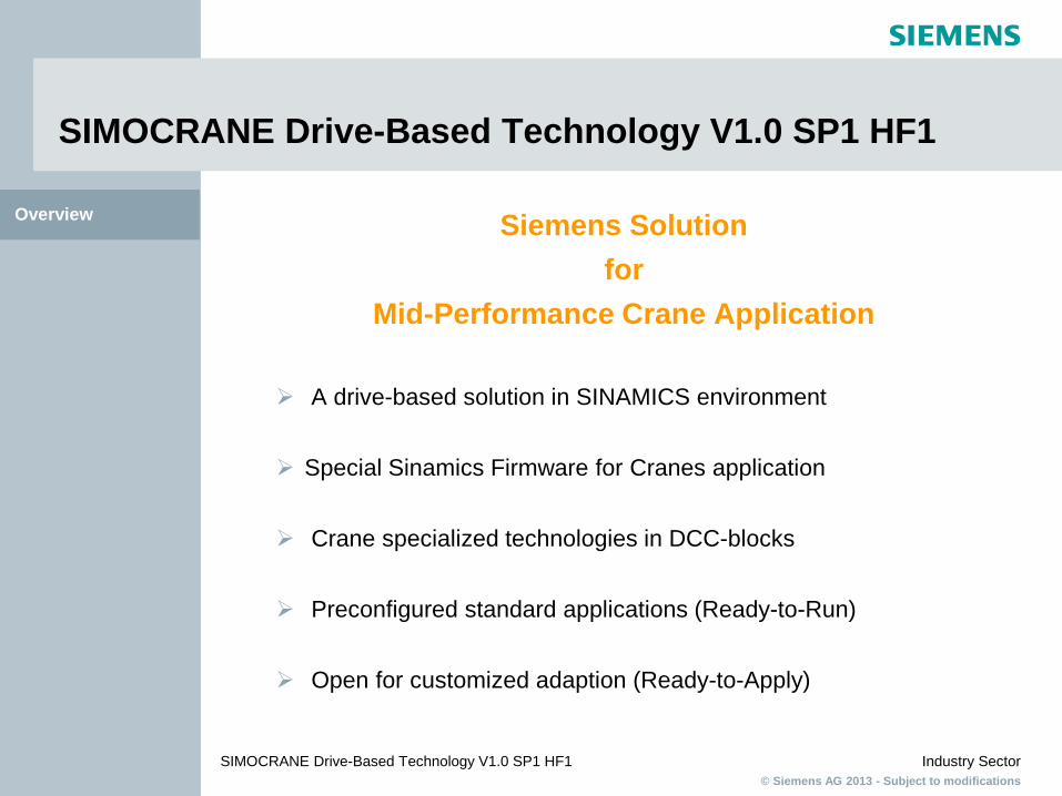
SIMOCRANE Drive-Based Technology V1.0 SP1 HF1
Siemens Solution for
Mid-Performance Crane Application
A drive-based solution in SINAMICS environment
Special Sinamics Firmware for Cranes application
Crane specialized technologies in DCC-blocks
Preconfigured standard applications (Ready-to-Run)
Open for customized adaption (Ready-to-Apply)
Overview

© Siemens AG 2013 - Subject to modifications Industry Sector
SIMOCRANE Drive-Based Technology V1.0 SP1 HF1
MC Cranes Our product portfolio
S I M
O C
R A
N E
Motion Controller
Drive Controller
Drives
P l a
t f o
r m
Crane Technology
Crane Management System Advanced Technology
Motors
Basic Technology
Sway Control
Skew Control
2D-Trajectory
Book- size Chassis
Crane Cabinet Modules
Basic Technology V3.0
SIMOTION D435-2
CU320-2
1PH8
ECO Technology
Truck Position System
1LA8/ 1LL8
(Remote) CMS CMS Lite
1LP4/6 1LG4/6
Drive-Based Technology
CU310-2
PM340 PM250
Mid Performance High Performance

© Siemens AG 2013 - Subject to modifications Industry Sector
SIMOCRANE Drive-Based Technology V1.0 SP1 HF1
Product Introduction
© Siemens AG 2013 - Subject to modifications Industry Sector
SIMOCRANE Drive-Based Technology V1.0 SP1 HF1
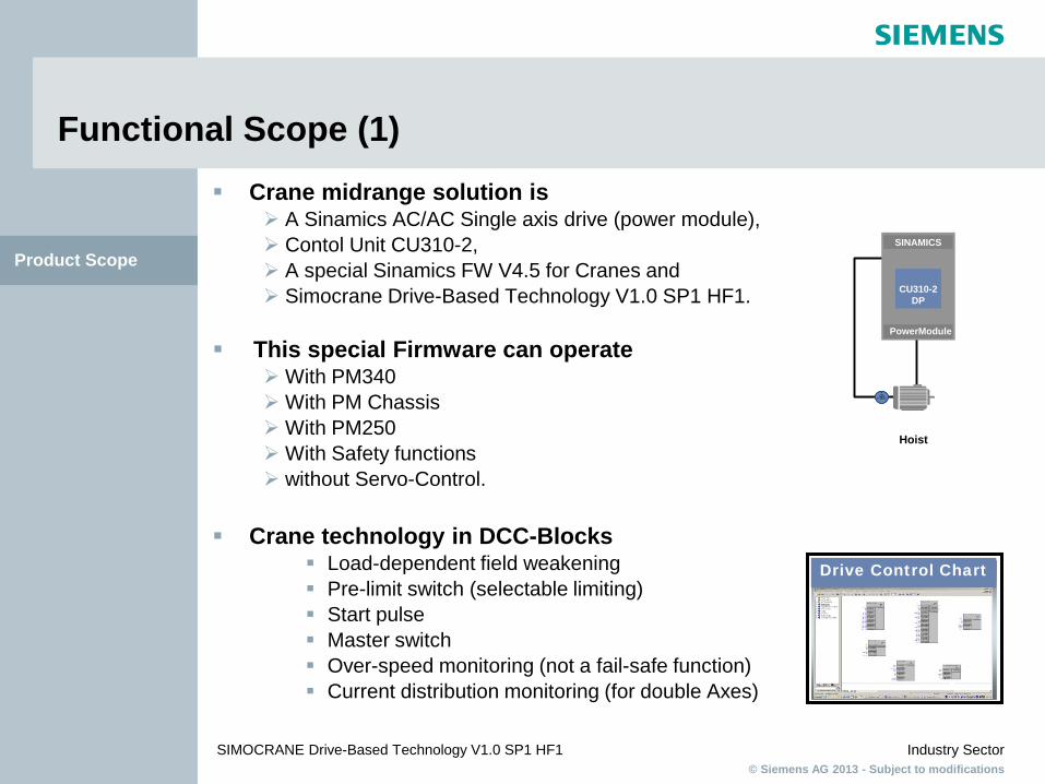
Functional Scope (1) Crane midrange solution is
A Sinamics AC/AC Single axis drive (power module), Contol Unit CU310-2, A special Sinamics FW V4.5 for Cranes and Simocrane Drive-Based Technology V1.0 SP1 HF1.
This special Firmware can operate
With PM340 With PM Chassis With PM250 With Safety functions without Servo-Control.
Crane technology in DCC-Blocks
Load-dependent field weakening Pre-limit switch (selectable limiting) Start pulse Master switch Over-speed monitoring (not a fail-safe function) Current distribution monitoring (for double Axes)
Product Scope
Hoist
SINAMICS
CU310-2 DP
PowerModule
Drive Control Chart

© Siemens AG 2013 - Subject to modifications Industry Sector
SIMOCRANE Drive-Based Technology V1.0 SP1 HF1
Functional Scope (2) Standard applications via I/O-onboard or via Profibus
Selectable via I/O-onboard or via Profibus Selectable with analogue or digital master-switch Combination of Startpulse with brake control SingleAxis application for Hoist or Trolley or Gantry DoubleAxes application for Master-Slave torque control Configuration via scripting
Sinamics functionality Time-optimized positioning for a single axis Master-slave closed-loop torque control Brake control Integrated Safety
The Crane DCC-chart is know-how protected, therefore, it can not be opened. The customized DCC application can be made in another DCC-chart under other Drive-Object (e.g. CU). There is no online-help in Sinamics Starter for user defined parameters. The grab function and synchronous operation are not parts of this product.
Product Scope

© Siemens AG 2013 - Subject to modifications Industry Sector
SIMOCRANE Drive-Based Technology V1.0 SP1 HF1
Scope of Supply
V1.0 SP1 HF1
Memory card (CF card) SINAMICS FW V4.5.1 for
Cranes
CD with Cranes DCC blocks Standard applications Documentation
Product Scope

© Siemens AG 2013 - Subject to modifications Industry Sector
SIMOCRANE Drive-Based Technology V1.0 SP1 HF1
Configuration Example of OHBC with Onboard I/O-signal
Product Scope
Hoist
SINAMICS CU310-2
SINAMICS
CU310-2 SINAMICS CU310-2
Meisterschalter
Cross travel Long travel

© Siemens AG 2013 - Subject to modifications Industry Sector
SIMOCRANE Drive-Based Technology V1.0 SP1 HF1
Configuration Example of OHBC with I/O Terminal Board Control
Product Scope
SINAMICS CU310
and TM31
SINAMICS CU310
and TM31
SINAMICS CU310
and TM31
Hoist Cross Travel Long Travel
Sender
Radio Control Receiver

© Siemens AG 2013 - Subject to modifications Industry Sector
SIMOCRANE Drive-Based Technology V1.0 SP1 HF1
Configuration Example of OHBC with Simatic Control via Profibus
Product Scope
SINAMICS CU310-2 DP
SINAMICS CU310-2 DP
SINAMICS CU310-2 DP
SINAMICS CU310-2 DP
SIMOCRANE CMSLite SIMATIC
S7-300
Main
Hoist
Auxiliary Hoist Cross Travel Long Travel 1
SINAMICS CU310-2 DP
Long Travel 2

© Siemens AG 2013 - Subject to modifications Industry Sector
SIMOCRANE Drive-Based Technology V1.0 SP1 HF1
Commissioning Guideline

© Siemens AG 2013 - Subject to modifications Industry Sector
SIMOCRANE Drive-Based Technology V1.0 SP1 HF1
Commissioning Guideline
1. Import project of SIMOCRANE Drive-Based Technology
2. Configuration of Drive object
3. Running Script
4. Motor identification (Sinamics Getting Started)
5. Parameterization of Crane DCC-blocks
Commissioning Guideline
Refer to the manual “Sinamics Getting Started” and
“SIMOCRANE Drive-Based Technology”, Chapter 6
Simocrane
Simocrane
Simocrane
Sinamics
Sinamics
© Siemens AG 2013 - Subject to modifications Industry Sector
SIMOCRANE Drive-Based Technology V1.0 SP1 HF1
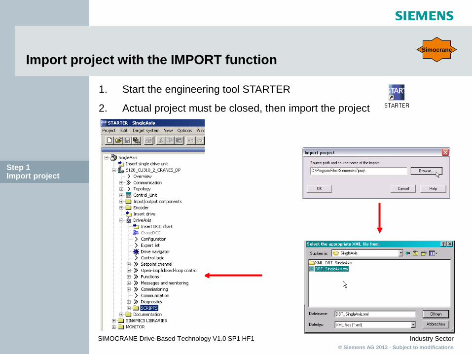
Import project with the IMPORT function
1. Start the engineering tool STARTER
2. Actual project must be closed, then import the project
Step 1 Import project
Simocrane

© Siemens AG 2013 - Subject to modifications Industry Sector
SIMOCRANE Drive-Based Technology V1.0 SP1 HF1
Configuration of the Drive Object (DO)
Step 2 Configuration DO
Sinamics

© Siemens AG 2013 - Subject to modifications Industry Sector
SIMOCRANE Drive-Based Technology V1.0 SP1 HF1
Select control method
Step 2 Configuration DO
Sinamics
© Siemens AG 2013 - Subject to modifications Industry Sector
SIMOCRANE Drive-Based Technology V1.0 SP1 HF1
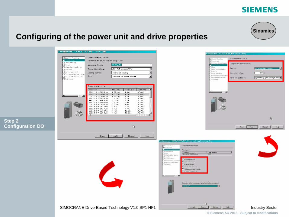
Configuring of the power unit and drive properties
Step 2 Configuration DO
Sinamics

© Siemens AG 2013 - Subject to modifications Industry Sector
SIMOCRANE Drive-Based Technology V1.0 SP1 HF1
Configuring of motor
Step 2 Configuration DO
Sinamics

© Siemens AG 2013 - Subject to modifications Industry Sector
SIMOCRANE Drive-Based Technology V1.0 SP1 HF1
Configuring of holding brake and encoder
Step 2 Configuration DO
Sinamics

© Siemens AG 2013 - Subject to modifications Industry Sector
SIMOCRANE Drive-Based Technology V1.0 SP1 HF1
Select drive functions, communication frame type ..
Step 2 Configuration DO
Sinamics

© Siemens AG 2013 - Subject to modifications Industry Sector
SIMOCRANE Drive-Based Technology V1.0 SP1 HF1
Summary
Step 2 Configuration DO
Sinamics

© Siemens AG 2013 - Subject to modifications Industry Sector
SIMOCRANE Drive-Based Technology V1.0 SP1 HF1
Check Topology
Step 2 Configuration DO
Sinamics

© Siemens AG 2013 - Subject to modifications Industry Sector
SIMOCRANE Drive-Based Technology V1.0 SP1 HF1
Execute Script file
Step 3 Running Script
Simocrane

© Siemens AG 2013 - Subject to modifications Industry Sector
SIMOCRANE Drive-Based Technology V1.0 SP1 HF1
Script file window
Step 3 Running Script
Simocrane
© Siemens AG 2013 - Subject to modifications Industry Sector
SIMOCRANE Drive-Based Technology V1.0 SP1 HF1
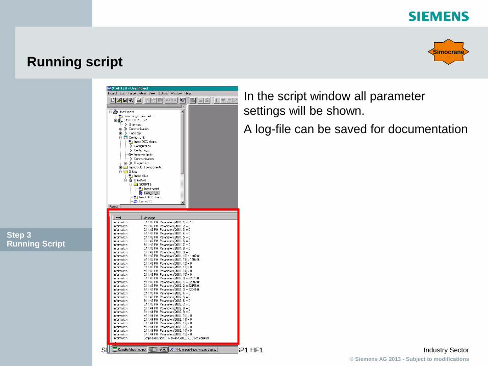
Running script
In the script window all parameter settings will be shown. A log-file can be saved for documentation
Step 3 Running Script
Simocrane

© Siemens AG 2013 - Subject to modifications Industry Sector
SIMOCRANE Drive-Based Technology V1.0 SP1 HF1
Setpoint channel in CU310-2 after running script (via Profibus control) Simocrane
Step 3 Running Script

© Siemens AG 2013 - Subject to modifications Industry Sector
SIMOCRANE Drive-Based Technology V1.0 SP1 HF1
Hoist Setpoint channel in CU310-2 after running script (via Onboard I/O with digital masterswitch or Profibus control)
Combination of Brake control and
StartPulse
Digital Master-Switch
Simocrane
Step 3 Running Script

© Siemens AG 2013 - Subject to modifications Industry Sector
SIMOCRANE Drive-Based Technology V1.0 SP1 HF1
Download into CF-card
Save and compile the project and then the project can be downloaded in two ways: 1. With STARTER go online via Profibus to SINAMICS CU310-2 and download the project into the device.
2. Put the Compact Flash card into a card reader and download
the project direct to the CF card and then put the CF card into the device.
Step 3 Running Script
Sinamics
© Siemens AG 2013 - Subject to modifications Industry Sector
SIMOCRANE Drive-Based Technology V1.0 SP1 HF1
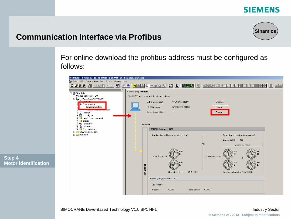
Communication Interface via Profibus
For online download the profibus address must be configured as follows:
Sinamics
Step 4 Motor identification

© Siemens AG 2013 - Subject to modifications Industry Sector
SIMOCRANE Drive-Based Technology V1.0 SP1 HF1
Communication Interface via Profibus
The profibus address is entered here. (This must correspond to the profibus address found on the CU310-2)
The profibus address can be set on the CU310-2 by setting the switches found underneath the BOP.
Sinamics
Step 4 Motor identification

© Siemens AG 2013 - Subject to modifications Industry Sector
SIMOCRANE Drive-Based Technology V1.0 SP1 HF1
Communication interface via Ethernet (1)
For using an Ethernet connection to connect to the control unit select the accessible nodes button to find device.
Sinamics
Step 4 Motor identification

© Siemens AG 2013 - Subject to modifications Industry Sector
SIMOCRANE Drive-Based Technology V1.0 SP1 HF1
Communication interface via Ethernet (2)
If the device is not found immediately: 1. Set access point to device in the accessible nodes tab.
Sinamics
Step 4 Motor identification

© Siemens AG 2013 - Subject to modifications Industry Sector
SIMOCRANE Drive-Based Technology V1.0 SP1 HF1
Communication interface via Ethernet (3)
2. Set the PG/PC interface in the accessible nodes tab. (Tip: Select component which has <Active> written after it).
Sinamics
Step 4 Motor identification

© Siemens AG 2013 - Subject to modifications Industry Sector
SIMOCRANE Drive-Based Technology V1.0 SP1 HF1
Communication interface via Ethernet (4)
3. Select search for accessible nodes again. 4. When the device is found note the IP address.
Sinamics
Step 4 Motor identification
© Siemens AG 2013 - Subject to modifications Industry Sector
SIMOCRANE Drive-Based Technology V1.0 SP1 HF1
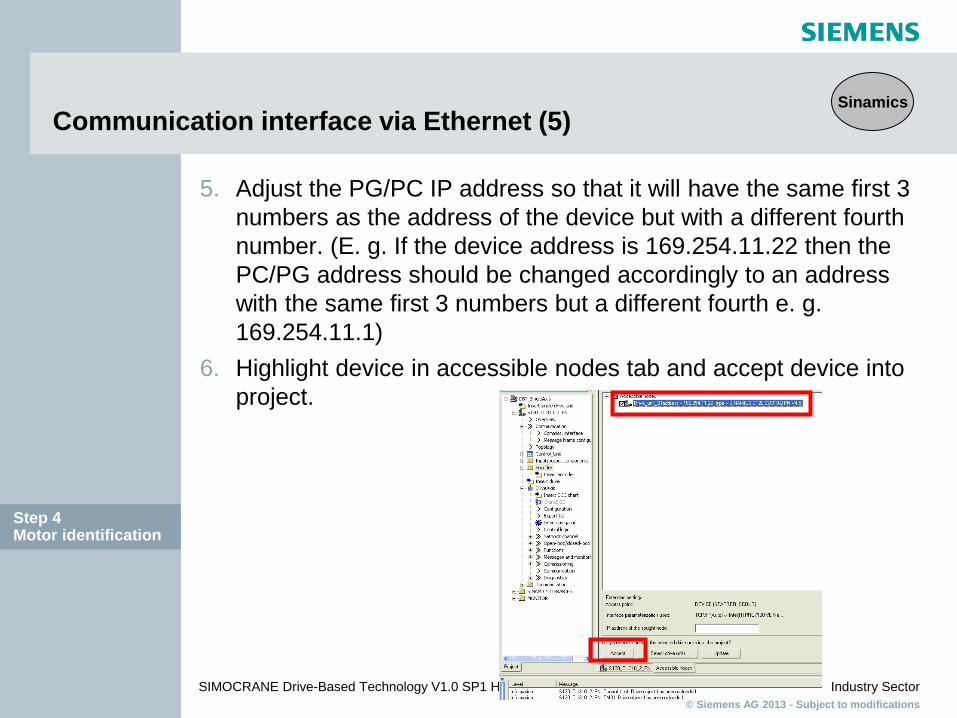
Communication interface via Ethernet (5)
5. Adjust the PG/PC IP address so that it will have the same first 3 numbers as the address of the device but with a different fourth number. (E. g. If the device address is 169.254.11.22 then the PC/PG address should be changed accordingly to an address with the same first 3 numbers but a different fourth e. g. 169.254.11.1)
6. Highlight device in accessible nodes tab and accept device into project.
Sinamics
Step 4 Motor identification

© Siemens AG 2013 - Subject to modifications Industry Sector
SIMOCRANE Drive-Based Technology V1.0 SP1 HF1
Overview of drive navigator
Step 4 Motor identification
Sinamics

© Siemens AG 2013 - Subject to modifications Industry Sector
SIMOCRANE Drive-Based Technology V1.0 SP1 HF1
Overview of I/O-Signals
Analogue
Digital
Sinamics
Step 4 Motor identification
© Siemens AG 2013 - Subject to modifications Industry Sector
SIMOCRANE Drive-Based Technology V1.0 SP1 HF1
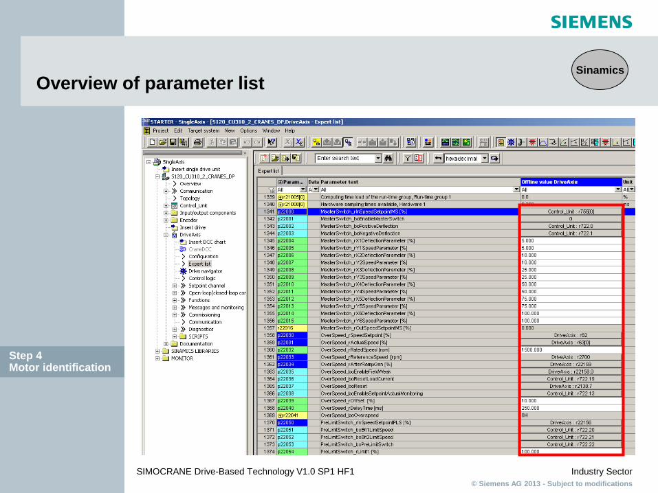
Overview of parameter list Sinamics
Step 4 Motor identification

© Siemens AG 2013 - Subject to modifications Industry Sector
SIMOCRANE Drive-Based Technology V1.0 SP1 HF1
Mainstream of speed setpoint and closed-loop control
Speed controller Torque setpoints Torque limiting
DRIVE-CLiQ
Current setpoint filter Current controller Power unit
Ramp function generator
Setpoint filter+precontrol
Speed setpoint
M
Step 4 Motor identification
Sinamics
© Siemens AG 2013 - Subject to modifications Industry Sector
SIMOCRANE Drive-Based Technology V1.0 SP1 HF1
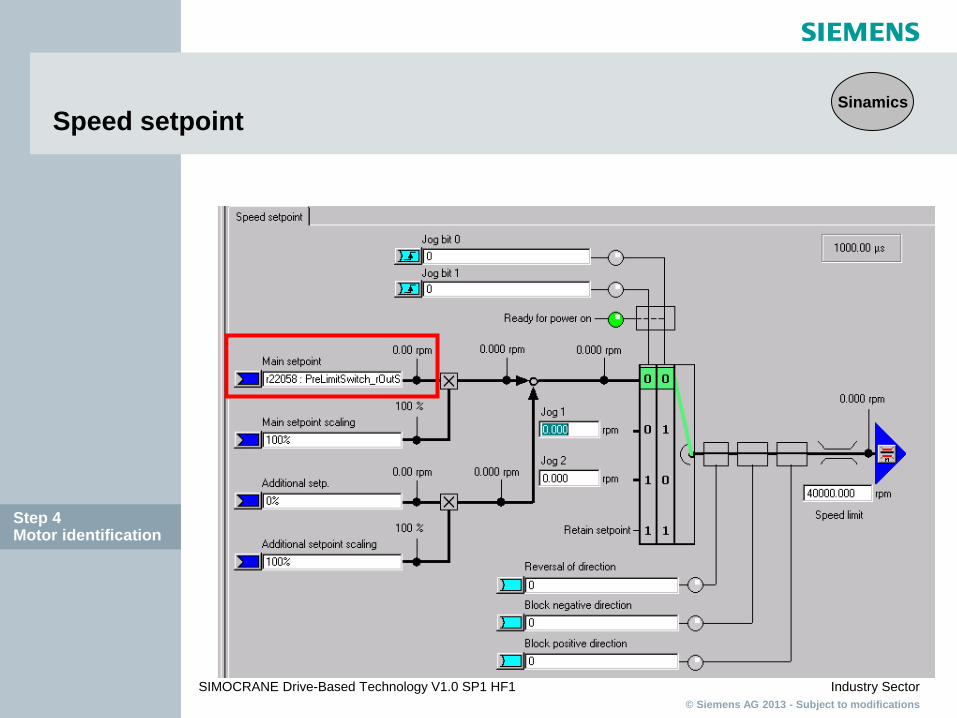
Speed setpoint
Step 4 Motor identification
Sinamics

© Siemens AG 2013 - Subject to modifications Industry Sector
SIMOCRANE Drive-Based Technology V1.0 SP1 HF1
Ramp-function generator
Step 4 Motor identification
Sinamics

© Siemens AG 2013 - Subject to modifications Industry Sector
SIMOCRANE Drive-Based Technology V1.0 SP1 HF1
Ramp-function generator
Simple ramp-function generator
Extended ramp-function generator
Step 4 Motor identification
Sinamics
© Siemens AG 2013 - Subject to modifications Industry Sector
SIMOCRANE Drive-Based Technology V1.0 SP1 HF1
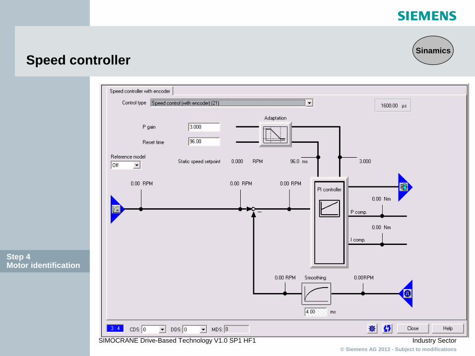
Speed controller
Step 4 Motor identification
Sinamics

© Siemens AG 2013 - Subject to modifications Industry Sector
SIMOCRANE Drive-Based Technology V1.0 SP1 HF1
Upper and Lower Torque Limit
Step 4 Motor identification
Sinamics

© Siemens AG 2013 - Subject to modifications Industry Sector
SIMOCRANE Drive-Based Technology V1.0 SP1 HF1
Introduction stationary measurement
Step 4 Motor identification
Sinamics

© Siemens AG 2013 - Subject to modifications Industry Sector
SIMOCRANE Drive-Based Technology V1.0 SP1 HF1
Purpose of stationary measurement (refer to Chapter 6.3) SINAMICS Drive Object Stationary measurement Equivalent circuit diagram data Total resistance for: power cable resistance and stator resistance
IGBT on-state voltage or compensation for the IGBT lockout times
Control Panel (speed direction check, if necessary directional change, p1821)
Step 4 Motor identification
Sinamics

© Siemens AG 2013 - Subject to modifications Industry Sector
SIMOCRANE Drive-Based Technology V1.0 SP1 HF1
Start stationary measurement
1. Select stationery measurement from the drop down menu. 2. Activate measurement.
Step 4 Motor identification
Sinamics

© Siemens AG 2013 - Subject to modifications Industry Sector
SIMOCRANE Drive-Based Technology V1.0 SP1 HF1
Results of the stationary measurement
Step 4 Motor identification
Sinamics

© Siemens AG 2013 - Subject to modifications Industry Sector
SIMOCRANE Drive-Based Technology V1.0 SP1 HF1
Start stationary measurement
1. Select control panel. 2. Select assume control priority. 3. Tick the enables box. 4. Select the green I button and the test begins.
Step 4 Motor identification
Sinamics

© Siemens AG 2013 - Subject to modifications Industry Sector
SIMOCRANE Drive-Based Technology V1.0 SP1 HF1
Purpose of rotating measurement (refer to Chapter 6.3)
SINAMICS Drive Object Rotating Measurement and Speed Controller Optimization Measurement of magnetization characteristic Measurement of magnetization current Speed controller optimization Acceleration pre-control setting Setting for ratio between the total moment of inertia and
that for the motor
Step 4 Motor identification
Sinamics

© Siemens AG 2013 - Subject to modifications Industry Sector
SIMOCRANE Drive-Based Technology V1.0 SP1 HF1
Start turning measurement
1. After stationery measurement select deactivate measurement. 2. Then select next measurement. Repeat steps taken for stationery except select turning
measurement with encoder from the drop down menu,
Step 4 Motor identification
Sinamics
© Siemens AG 2013 - Subject to modifications Industry Sector
SIMOCRANE Drive-Based Technology V1.0 SP1 HF1
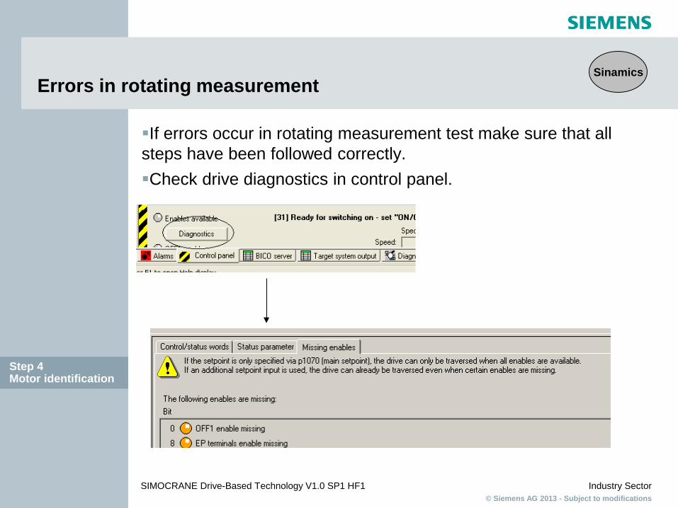
Errors in rotating measurement
Step 4 Motor identification
If errors occur in rotating measurement test make sure that all steps have been followed correctly. Check drive diagnostics in control panel.
Sinamics
© Siemens AG 2013 - Subject to modifications Industry Sector
SIMOCRANE Drive-Based Technology V1.0 SP1 HF1
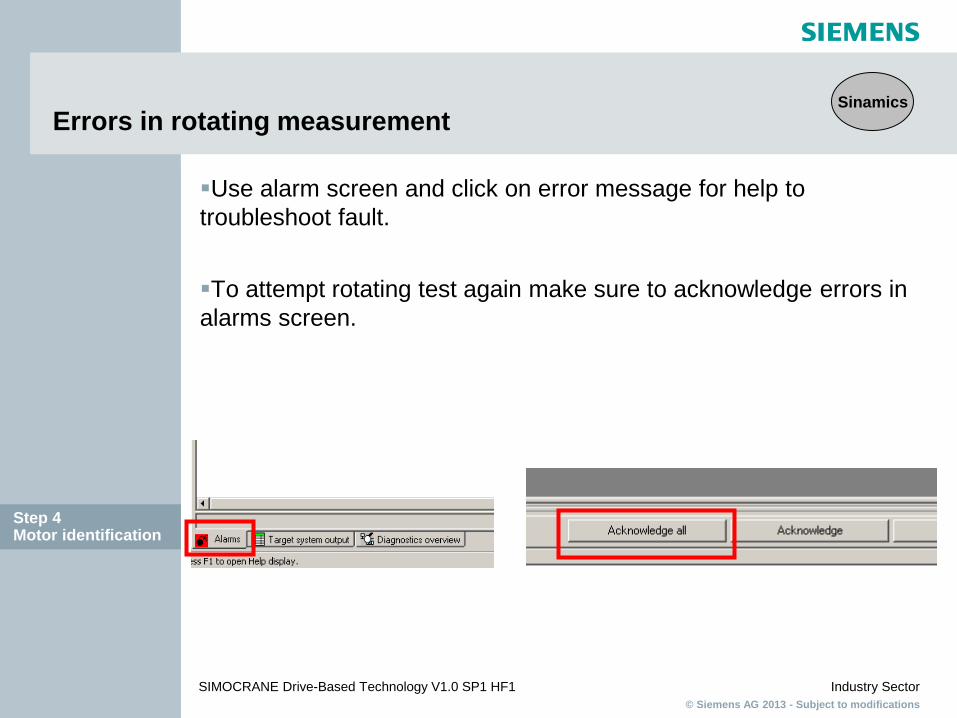
Errors in rotating measurement
Step 4 Motor identification
Use alarm screen and click on error message for help to troubleshoot fault. To attempt rotating test again make sure to acknowledge errors in alarms screen.
Sinamics

© Siemens AG 2013 - Subject to modifications Industry Sector
SIMOCRANE Drive-Based Technology V1.0 SP1 HF1
Results of the rotating measurement
Step 4 Motor identification
Sinamics

© Siemens AG 2013 - Subject to modifications Industry Sector
SIMOCRANE Drive-Based Technology V1.0 SP1 HF1
Alternative to rotating measurement (refer to Chapter 6.3)
If the rotating measurement cannot be performed, it is possible to correct manually the missed rotating measurement settings: - To correct manually the magnetizing current and magnetizing inductance
- Speed control optimization by re-calculating the control parameters (p0340) or by optimizing manually the controller
Refer to the manual “SIMOCRANE Drive-Based Technology”, Chapter 6.3
Step 4 Motor identification
Simocrane

© Siemens AG 2013 - Subject to modifications Industry Sector
SIMOCRANE Drive-Based Technology V1.0 SP1 HF1
Open the Expert list
Select DriveAxis with the right mouse, a new window will be opened. Select Expert and Expert list
Step 5 Parameterization Crane DCC
Simocrane

© Siemens AG 2013 - Subject to modifications Industry Sector
SIMOCRANE Drive-Based Technology V1.0 SP1 HF1
DCC Parameters in the Expert list
Step 5 Parameterization Crane DCC
Simocrane

© Siemens AG 2013 - Subject to modifications Industry Sector
SIMOCRANE Drive-Based Technology V1.0 SP1 HF1
DCC_MasterSwitch (refer to Chapter 4.2)
In order that for low deflection angles lower speed setpoints are obtained than those that correspond linearly to the deflection angle, the master switch setpoint is modeled through a non-linear function. This allows the drive to be precisely positioned in the manual mode.
Step 5 Parameterization Crane DCC
Simocrane

© Siemens AG 2013 - Subject to modifications Industry Sector
SIMOCRANE Drive-Based Technology V1.0 SP1 HF1
DCC_DigitalMasterSwitch (refer to Chapter 7.1.1) Simocrane
DI0
DI0
+ D
I2
P. Speed 1
P. Speed 4
P. Speed 2
Digtal Input
P. Speed 3
N. Speed 4
N. Speed 1
N. Speed 3
N. Speed 2
Speed
DI0
+ D
I2 +
DI3
DI0
+ D
I2 +
DI3
+ D
I8
DI1
+ D
I2
DI1
+ D
I2 +
DI3
DI1
+ D
I2 +
DI3
+ D
I8
DI1

© Siemens AG 2013 - Subject to modifications Industry Sector
SIMOCRANE Drive-Based Technology V1.0 SP1 HF1
DCC_Startpulse (refer to Chapter 4.3)
For hoists, when starting (i.e. opening the hoisting gear brake) with freely suspended load, often the load undesirably sags. The reason for this is that the torque is not available when starting. When starting with a suspended load, the torque must be quickly established.
Step 5 Parameterization Crane DCC
Simocrane

© Siemens AG 2013 - Subject to modifications Industry Sector
SIMOCRANE Drive-Based Technology V1.0 SP1 HF1
DCC_Startpulse in combination of Brake control
Step 5 Parameterization Crane DCC
Brake Control
Start Pulse
Brake open
Simocrane
Brake close
© Siemens AG 2013 - Subject to modifications Industry Sector
SIMOCRANE Drive-Based Technology V1.0 SP1 HF1
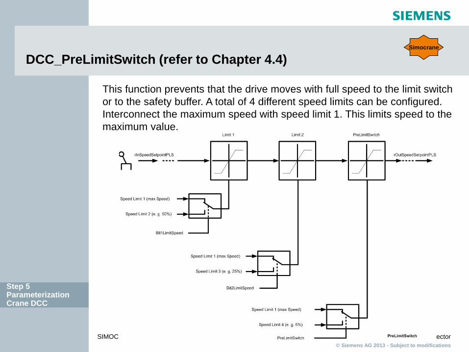
DCC_PreLimitSwitch (refer to Chapter 4.4)
This function prevents that the drive moves with full speed to the limit switch or to the safety buffer. A total of 4 different speed limits can be configured. Interconnect the maximum speed with speed limit 1. This limits speed to the maximum value.
Step 5 Parameterization Crane DCC
Simocrane

© Siemens AG 2013 - Subject to modifications Industry Sector
SIMOCRANE Drive-Based Technology V1.0 SP1 HF1
DCC_Overspeed (refer Chapter 4.5)
Function 1 to monitor the actual velocity for an overspeed condition. Compared value can be either in range of the rated speed or in field weakening area.
Step 5 Parameterization Crane DCC
Function 2 to monitor continuously setpoint-actual value deviation
Simocrane

© Siemens AG 2013 - Subject to modifications Industry Sector
SIMOCRANE Drive-Based Technology V1.0 SP1 HF1
DCC_CurrentDistributionMon (refer to Chapter 4.6)
This function can be used for master-slave operation or synchronous operation. The block monitors that the total current of both drives is distributed evenly. In synchronous operation, the current setpoint value is monitored for the two drives. In master-slave operation, the current actual values of two drives are monitored.
If the difference of the setpoint or actual currents of both drives exceeds the configured values for deviation and time, then output r22037 "boFaultCurrentMonitoring" is set. Step 5
Parameterization Crane DCC
Simocrane

© Siemens AG 2013 - Subject to modifications Industry Sector
SIMOCRANE Drive-Based Technology V1.0 SP1 HF1
DCC_LoadDependingFieldWeak (refer to Chapter 4.7 and 6.5)
When selecting field weakening, e.g. using the master switch, a supplementary speed setpoint for field weakening, which is permissible for the actual load, is generated. Theoretical basics and equations The steady-state load torque is calculated as follows: MM = MLoad + MFriction MM: Motor torque MLoad: Load torque MFriction: Frictional torque Commissioning instructions 1. To generate the measured variables (refer to chapter 6.5.2.1) 2. Compensating the frictional torque (refer to chapter 6.5.2.2) 3. Correcting the efficiency (refer to chapter 6.5.2.3) 4. Calculating the physical size of the load (refer to chapter 6.5.2.4)
Step 5 Parameterization Crane DCC
Simocrane

© Siemens AG 2013 - Subject to modifications Industry Sector
SIMOCRANE Drive-Based Technology V1.0 SP1 HF1
After commissioning save the project
After the Commissioning is finished, following steps must be done: Copy RAM to ROM (all settings will be saved on CF card)
If the parameter settings in the CU310 are changed online, then upload the project to PG and save the project in the STARTER.
Do a copy of the complete CF flash card to the hard-disc as a backup.
Step 5 Parameterization Crane DCC
Sinamics

© Siemens AG 2013 - Subject to modifications Industry Sector
SIMOCRANE Drive-Based Technology V1.0 SP1 HF1
SIMOCRANE Product Support SIMOCRANE Product-Support (news, FAQs, Manuals,..) in Internet http://support.automation.siemens.com/WW/view/en/10807397/130000
Crane Application note: http://support.automation.siemens.com/WW/view/de/48342008/136000
New: Support request via Internet (Product Simocrane) : http://support.automation.siemens.com
New: Hotline EUROPA – Telefon: +49 (0) 911 895 7 222
– Fax: +49 (0) 911 895 7 223
– Email: [email protected]
New: Hotline AMERICA – Telefon: +1 423 262 5710
– Fax: +1 423 262 2231
– Email: [email protected]
New: Hotline ASIA / PACIFIC – Telefon: +86 10 6475 7575
– Fax: +86 10 6474 7474
– Email: [email protected] Support
Simocrane

© Siemens AG 2013 - Subject to modifications Industry Sector
SIMOCRANE Drive-Based Technology V1.0 SP1 HF1
SIMOCRANE Drive-Based Technology V1.0 SP1 HF1