Descent and Landing Triggers for the Orion Multi-Purpose ...
19
AAS 13-074 Descent and Landing Triggers for the Orion Multi-Purpose Crew Vehicle Exploration Flight Test-1 Brian D. Bihari Charity J. Duke Jeffrey D. Semrau UTC Aerospace Systems Lockheed Martin Honeywell 36 th ANNUAL AAS GUIDANCE AND CONTROL CONFERENCE February 1 - February 6, 2013 Sponsored by Breckenridge, Colorado Rocky Mountain Section AAS Publications Office, P.O. Box 28130 - San Diego, California 92198
Transcript of Descent and Landing Triggers for the Orion Multi-Purpose ...
AAS 13-074
Descent and Landing Triggers for the Orion Multi-Purpose Crew Vehicle
Exploration Flight Test-1
Brian D. Bihari Charity J. Duke Jeffrey D. Semrau UTC Aerospace Systems Lockheed Martin Honeywell
36th ANNUAL AAS GUIDANCE AND CONTROL CONFERENCE
February 1 - February 6, 2013 Sponsored by Breckenridge, Colorado Rocky Mountain Section
AAS Publications Office, P.O. Box 28130 - San Diego, California 92198

1
DESCENT AND LANDING TRIGGERS FOR THE ORION MULTI-PURPOSE CREW VEHICLE EXPLORATION FLIGHT TEST-1
Brian D. Bihari,* Charity J. Duke,† Jeffrey D. Semrau‡
The Orion Multi-Purpose Crew Vehicle (MPCV) will perform a flight test known as Exploration Flight Test-1 (EFT-1) currently scheduled for 2014. One of the primary functions of this test is to exercise all of the important Guidance, Navigation, Control (GN&C), and Propulsion systems, along with the flight software for future flights. The Descent and Landing segment of the flight is governed by the requirements levied on the GN&C system by the Landing and Recovery System (LRS). The LRS is a complex system of parachutes and flight control modes that ensure that the Orion MPCV safely lands at its designated target in the Pacific Ocean. The Descent and Landing segment begins with the jettisoning of the Forward Bay Cover and concludes with sensing touchdown. This paper discusses the requirements, design, testing, analysis and performance of the current EFT-1 Descent and Landing Triggers flight software.
INTRODUCTION
The Orion Exploration Flight Test-1 (EFT-1) mission is an unmanned space flight utilizing the Multi-Purpose Crew Vehicle (MPCV) Orion Crew Module (CM). One of the main purposes of this flight test is to test various MPCV systems prior to manned missions. This early flight will allow engineers to test the Guidance, Navigation, Control (GN&C) and Propulsion systems necessary for the entry portion of flight. Figure 1 shows the flight mission profile.1
Figure 1: EFT-1 Mission Profile
The Orion capsule is a similar shape to the Apollo Command Module but scaled up to allow for a crew
of up to four on missions beyond earth orbit such as to an asteroid, the Moon or Mars.
* Orion Entry MODE Team, UTC Aerospace Systems, 2224 Bay Area Blvd, Houston, TX 77058 † Orion GN&C, Lockheed Martin Space Systems Company, 12257 South Wadsworth Blvd, Littleton, CO 80127 ‡ Orion Entry MODE Team, Honeywell Inc., 2525 Bay Area Blvd, Ste 200, Houston, TX 77058

2
CHALLENGES
The Orion Landing and Recovery System (LRS) has undergone a vast array of changes since the program’s inception. It has proven to be one of the most challenging, complex, and evolving systems on the spacecraft. Several trade studies and assessments have been performed across multiple disciplines and subsystems to address this phase of flight. The primary drivers of these studies are safety, reliability, and cost. Changes to mission objectives, program requirements, vehicle mass properties, and GN&C subsystems have all led to updates of the LRS. Some of the major issues that have had to be overcome include: changes to the vehicle mass properties and outer mold line, limiting the vehicle vertical descent rate (e.g. landing loads on vehicle and crew), changes to the aerodynamics (or our understanding of them) of the vehicle, ability to control the heading error at touchdown, sensing of touchdown, and systems failures (e.g. navigation degradation, parachute failures, Reaction Control System (RCS) failures, etc.). A few of the major trade studies that have been examined to address the LRS system include: land vs. water landings; crew size (7 to 4); segmented vs. monolithic Forward Bay Cover (FBC); FBC removal (FBC parachutes, drogues, thrusters, airbags); landing retro-rockets, confluence retros, anti-tipover rockets; landing airbags of various configurations; parachute attachment and confluence point; changes to the vehicle hang angle under the chutes; textile vs. steel parachute risers; use of a torque riser (anti-twist keeper); the number, types, sizes, reefing schedules, and porosity of various parachutes; chute deployment architectures (e.g. drogue deployed main parachutes); various navigation systems (GPS, baro-altimeter, IMU); the number, size, thrust and orientation of Reaction Control System (RCS) system and its use under the parachutes; and the number, size, location and shape of Command Module Up-righting System (CMUS) airbags.2.3 All of the trades and challenges listed above have had a direct impact on the LRS sequence and thus consequently on the Descent and Landing Triggers Flight Software (DLTRIG FSW) which is responsible for ensuring the LRS events occur as designed. DESCENT AND LANDING REQUIREMENTS
A set of GN&C requirements generated by NASA and the prime contractor, Lockheed Martin will be evaluated for the LRS during the EFT-1 mission. These requirements include: drogue parachute deployment conditions, landing accuracy, landing orientation of the capsule, vertical descent rate, RCS shutoff, and touchdown detection. Additionally, EFT-1 Flight Test Objectives include the demonstration of the jettison of the Forward Bay Cover and drogue and main parachute deployment and release. Figure 2 shows the flow for the descent and landing requirements.4
Figure 2: Descent and Landing Requirements Flow
3
NOMINAL LANDING AND RECOVERY SEQUENCE
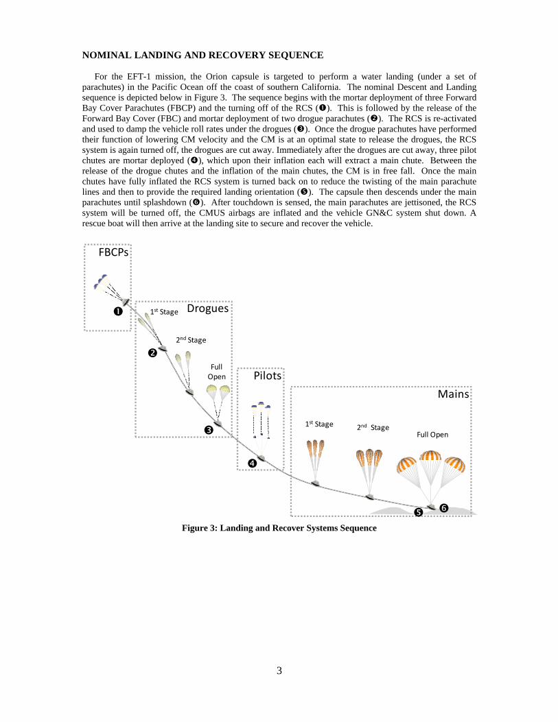
For the EFT-1 mission, the Orion capsule is targeted to perform a water landing (under a set of parachutes) in the Pacific Ocean off the coast of southern California. The nominal Descent and Landing sequence is depicted below in Figure 3. The sequence begins with the mortar deployment of three Forward Bay Cover Parachutes (FBCP) and the turning off of the RCS (). This is followed by the release of the Forward Bay Cover (FBC) and mortar deployment of two drogue parachutes (). The RCS is re-activated and used to damp the vehicle roll rates under the drogues (). Once the drogue parachutes have performed their function of lowering CM velocity and the CM is at an optimal state to release the drogues, the RCS system is again turned off, the drogues are cut away. Immediately after the drogues are cut away, three pilot chutes are mortar deployed (), which upon their inflation each will extract a main chute. Between the release of the drogue chutes and the inflation of the main chutes, the CM is in free fall. Once the main chutes have fully inflated the RCS system is turned back on to reduce the twisting of the main parachute lines and then to provide the required landing orientation (). The capsule then descends under the main parachutes until splashdown (). After touchdown is sensed, the main parachutes are jettisoned, the RCS system will be turned off, the CMUS airbags are inflated and the vehicle GN&C system shut down. A rescue boat will then arrive at the landing site to secure and recover the vehicle.
Figure 3: Landing and Recover Systems Sequence
Drogues
Pilots
Mains
1st Stage 2nd StageFull Open
Full Open
1st Stage
2nd Stage
FBCPs
4
DESCENT AND LANDING TRIGGERS FLIGHT SOFTWARE DESIGN5 Overview
The Descent and Landing Triggers (DLTRIG) Flight Software (FSW) is designed to operate during the descent and landing phases of flight. It outputs the following four variables:
1. Command to deploy the FBC parachutes 2. Command to jettison the drogue parachutes 3. The current vehicle control mode (to be used by the controls FSW) 4. Flag indicating if the touchdown of the Crew Module has been detected
It should be noted that the DLTRIG FSW does not actually command the deployment of the FBC
parachutes or the jettison of the drogue parachutes; it merely determines if GN&C is ready for these events to occur and passes those commands on to the Timeline and Vehicle Manager (TVM) software, which is responsible for the firing of the pyros based on GN&C’s recommendation and other system considerations.
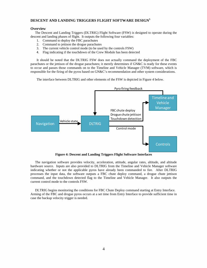
The interface between DLTRIG and other elements of the FSW is depicted in Figure 4 below.
Figure 4: Descent and Landing Triggers Flight Software Interfaces
The navigation software provides velocity, acceleration, attitude, angular rates, altitude, and altitude
hardware source. Inputs are also provided to DLTRIG from the Timeline and Vehicle Manager software indicating whether or not the applicable pyros have already been commanded to fire. After DLTRIG processes the input data, the software outputs a FBC chute deploy command, a drogue chute jettison command, and the touchdown detected flag to the Timeline and Vehicle Manager. It also outputs the current control mode to the controls FSW.
DLTRIG begins monitoring the conditions for FBC Chute Deploy command starting at Entry Interface. Arming of the FBC and drogue pyros occurs at a set time from Entry Interface to provide sufficient time in case the backup velocity trigger is needed.
Navigation
Timeline and Vehicle Manager
Controls
Pyro firing feedback
Vehicle state
Control mode
FBC chute deployDrogue chute jettisonTouchdown detection
DLTRIG

5
Control Modes There are four different control modes that can be set by the DLTRIG FSW and sent to the controls
FSW to be implemented. These four modes and listed and described below:
Table 1: CM Control Modes for Descent and Landing Phases of Flight CM Control Mode Description RCS Inhibited Inhibits the firing of the RCS thrusters Drogue Rate Damping Damps the heading error rate while under drogue chutes Main Anti-Twist Prevents the twist-up of the main parachute lines Landing Reorient Aligns the body roll with the velocity vector to meet
structural requirements for touchdown During a nominal entry (with an aided altitude source), the descent and landing control mode is
determined based on a combination of altitude triggers and timers as illustrated below:
Figure 5: Touchdown Control Mode Relative & Geodetic Altitude4
During a contingency (with an un-aided altitude source), the descent and landing control mode is based
largely on timers.
Nominal and Contingency Operations The operational mode of the DLTRIG FSW is largely tied to the health of the navigation subsystem.
During nominal entry scenarios, the altitude is derived from either the vehicle’s Global Positioning System (GPS) or the baro-altimeter. In this case, events are triggered using a combination of elapsed-time, vehicle rate, and altitude conditions.
During contingency entry scenarios, the navigated altitude is not aided by the GPS or baro-altimeter. In
this case, events use the backup logic that is based on either vehicle velocity or timers. The detailed DLTRIG logic employed in the nominal and contingency situations is explored in the subsequent sections.

6
NOMINAL DLTRIG LOGIC5
The nominal logic for the FBC parachute deploy command, drogue parachute jettison command, and
vehicle control mode is employed when the navigated altitude is aided by either the GPS or the baro-altimeter. The nominal logic for the touchdown detection flag is used when there is a sufficient deceleration upon touchdown (i.e. not a soft landing). A generic representation of the nominal DLTRIG architecture is provided in Figure 6 below. Red lines indicate events that are controlled by the Descent and Landing Triggers FSW and black lines indicate events that are controlled (via timers) through the Timeline and Vehicle Manager software.
The values for the altitude and timer triggers were determined using a combination of tests including: Capsule Parachute Assembly System (CPAS) parachute drop tests, integrated GN&C simulation analysis and aerodynamic wind tunnel and Computational Fluid Dynamics (CFD) testing.
Figure 6: Descent and Landing Triggers Nominal Logic
The FBC chute deploy is commanded once either of the following two conditions are met:
1. The vehicle is below the required FBC chute deploy altitude ceiling and the Smart FBC chute logic commands a deploy (additional information on the Smart FBC logic is provided in the next section)
2. The vehicle drops below the FBC chute deploy altitude floor
After the FBC chute deploy is commanded (and TVM deploys the chutes), TVM commands the jettison of the FBC based on a timer. A second TVM-based timer commands the deployment of the CM drogue chutes.
Next, the drogue chute jettison is commanded when either of the following two conditions are met: 1. The drogue chute disreef timer has expired, the vehicle is below the drogue jettison altitude
ceiling, and the Smart Drogue Release logic commands a deploy (additional information on the Smart Drogue Release logic is provided in the next section)
2. The vehicle drops below the drogue jettison altitude floor

7
After the drogue chute jettison is commanded (and TVM jettisons the drogue chutes), TVM commands the deployment of the main pilot chutes (and consequently the main chutes) after the appropriate timer is complete.
Finally, the touchdown detected flag is set when a sufficient deceleration is sensed (additional information is provided below). The following sections give a more detailed explanation of the Smart FBC chute deploy logic, the Smart Drogue Release logic, and the touchdown detection logic. Smart FBC Parachute Deploy
If the FBC has not yet been jettisoned, DLTRIG begins checking for the correct conditions to deploy the FBC Parachutes. Ideally, FBC chute deploy is initiated at the FBC chute deploy altitude floor. To ensure that the vehicle does not flip over before the altitude floor is reached, the Smart FBC Chute Deploy logic is employed. The Smart logic is enabled once the vehicle is below the defined FBC Chute Deploy ceiling altitude. This logic monitors the root-sum-square (RSS) of the pitch and yaw body rates (using filtered IMUs rates). If this value exceeds a specified threshold, the FBC Chute Deploy will be commanded. If the RSS of the pitch and yaw rates remains below the threshold, the FBC Chute Deploy will be commanded once the FBC Chute Deploy floor altitude is reached. Refer to Figure 7 for a plot of the operation of the Smart FBC Chute Deploy logic.
Figure 7: RSS of Pitch and Yaw Rates for Smart FBC Chute Deploy
Within the Altitude Ceiling and Floor Limits4 Smart Drogue Release
During the time under drogue parachutes the aerodynamic forces and moments can cause the CM to oscillate severely. If the drogue chutes are released at a high rate state of the CM, the CM could potentially flip over during deployment of the main chutes. To decrease the likelihood of this occurrence, the Smart Drogue Release (SDR) logic was developed. This logic monitors body rates and attempts to command a release of the drogues when the CM rates are at their optimal state.
The SDR logic calculates the RSS of the pitch (q) and yaw (r) body rates using the filtered IMU rates.
It then detects the peaks and troughs in the oscillation of the RSS of the pitch and yaw rate magnitude. When the rate magnitude is increasing, the SDR logic is in an ascending state. When the rate magnitude is decreasing, the SDR logic is in a descending state. When the logic switches from an ascending state to a

8
descending state, a potential peak is found. When the logic switches from a descending state to an ascending state, a potential trough is found.
Filtered IMU rates are used in SDR logic, however, some high frequency noise is still present in these
rate signals. Persistence checks are implemented for the detection of the rate state, peaks and troughs to ensure that the rate states, peaks, and troughs are properly detected. Without persistence, noise in the signal could be improperly detected as an ascending/descending rate or a peak/trough and the SDR logic would not perform as desired.
After the peak and trough are detected, the oscillation fraction is calculated. This fraction indicates
where the vehicle is in the oscillation sinusoid and is defined below:
_
Where all rates are magnitudes derived from the RSS of the pitch and yaw rates. Using this oscillation
fraction, the triggers are evaluated. Two triggers exist: one for the ascending state and one for the descending state. If the Smart Drogue Release state is ascending and the oscillation fraction is less than the ascending trigger, the Smart Drogue Release command will be set high. If the state is descending and the oscillation fraction is less than the descending trigger, the Smart Drogue Release command will be set high. Otherwise the Smart Drogue Release command remains low.
If the RSS of the pitch and yaw body rates is below a specified value, all the previous logic is ignored
and the Smart Drogue Release command is set high regardless of the oscillation fraction. This logic is used in cases where CM rates under the drogues are so low that a successful release can be commanded at any point in the oscillation.
Figure 8 demonstrates the operation of the Smart Drogue Release logic. In this figure the peak/trough detection persistence is set to zero.
Figure 8: Smart Drogue Release Logic Functional Example
As can be seen from the first subplot in Figure 8, a peak is detected immediately when the rate state
goes from ascending to descending (and similar logic for trough detection). The rate state is shown in the second subplot: white shading indicates an ascending state and gray shading indicates a descending state.

9
The computed oscillation fraction is also shown in this plot. In this case, the ascending trigger is set to zero so that the SDR command can never be set high when the rates are ascending. This prevents the command from being set high when the actual rates are higher than desired due to latency in the filter. For this example, the descending trigger is set to 0.5. Accordingly when the rate state is descending and the oscillation fraction is below the 0.5 limit (~50% of the way between the peak and the trough), the SDR command will be set high, as can be seen in the second and third subplots in Figure 8.
Figure 9 shows the use of the Drogue Jettison occurring between the ceiling and floor when the SDR
logic has been set.
Figure 9: Smart Drogue Release Logic within the Altitude Ceiling and Floor Limits5
Tuning of the SDR trigger values to yield optimal results was performed running a parametric analysis
of CM performance in the GN&C simulation for a variety of trigger values. Monte Carlo sets of 500 runs were executed for this task. All analyses performed to tune SDR trigger values were done with the expected max mass value of the CM and with one drogue disabled in the simulation. This configuration was used because it generates the most stressful CM rates, velocities, Mach numbers, and dynamic pressures at drogue release. It has been demonstrated in multiple simulations and by analytical analysis7,8 that two drogues can easily counteract the unstable CM aerodynamic moments currently predicted for the CM in the subsonic regime. With two drogues active, the current best estimate is that in 3,000 Monte Carlos sets none of the runs result in a CM flip or an apex forward orientation in the time period between drogue release and main deploy. However, in a one drogue situation the CM/drogue system is at best neutrally stable (and even then only once the drogue is fully open).
For reference, the typical time period between drogue release and inflation of the main chutes is
approximately 3 seconds. Due to system constraints, the RCS cannot be fired in this time period to maintain optimal CM attitude; hence the need to implement the SDR logic that minimizes the risk of the CM going apex forward during main parachute deployment. The consequences of the CM flipping or going apex forward during main deployment include fouling the main parachutes so that they are damaged
10
during deployment or cannot deploy at all, damaging the main risers such that they subsequently fail during inflation of the mains, or contact between the chute riser lines and the CM that damage CM structural components. All of these consequences can result in a loss of the EFT-1 test vehicle.
A simplified version of the SDR logic was used in the Orion Pad Abort 1 (PA-1) test which was flown
in May 2010. The primary distinction between SDR in PA-1 and EFT-1 is PA-1 SDR did not have persistence monitoring of the RSS q/r rate magnitude as part of its logic. PA-1 analysis of SDR showed it was optimal to release drogues only on descending rate magnitude of the RSS q/r, never on an ascending rate.
The data from the Monte Carlo sets showed that lowering the descending trigger results in fewer
predicted flips of the CM deployment. A lower descending trigger means the drogues will be release on a lower rate magnitude. Lower rates at drogue release assist in preventing the CM from going apex forward during main parachute deploy. The descending trigger value needs to be balanced against persistence and the typical rate frequency of the CM under the drogues. The typical frequency of the CM rate under the drogues is 0.5 Hz (2 sec). Configuring SDR to only release on any descending rate results in the SDR command on for only 1 sec of the rate cycle, a descending trigger of 0.5 lowers the time the SDR command can be on to 500 msec. The DLTRIG FSW executes at 40 Hz (25 msec). A persistence value of 3 lowers the time the SDR command is on in a typical rate oscillation to 425 msec. If one were to lower the descending trigger too low SDR would never satisfy its criteria to release drogues at an optimal rate. This would result in the drogues always being released at the SDR altitude floor regardless of the rates. This would result in an unacceptable risk of the CM going apex forward during main parachute deploy.

11
Touchdown Detection The nominal logic used to detect touchdown is based on vehicle acceleration. This logic is employed
regardless of the altitude source (i.e. the altitude does not have to be aided by the GPS or baro-altimeter). The nominal touchdown detection logic is evaluated once a specified time since drogue chutes jettison has elapsed and the vehicle is below an altitude threshold (or the altitude source un-aided). .
Once these initial conditions have been met, the vehicle acceleration is evaluated using 200 Hz acceleration data from the selected IMU. Since this data is provided at 200 Hz and the DLTRIG FSW is run at 40 Hz, a loop is set up in the Touchdown Detection logic to evaluate each sample from the IMUs. During each execution of this loop, the IMU sample is filtered using a second order Infinite Impulse Response (IIR) filter and then sent through a lever arm correction to find the acceleration at the center of gravity (CG) of the vehicle.
Once the acceleration vector of the vehicle at the CG is determined, the magnitude of the acceleration vector is taken. This acceleration magnitude is then checked against two separate limits: the RCS Acceleration Threshold and the Touchdown Acceleration Threshold. The RCS Acceleration Threshold is set less than the Touchdown Acceleration Threshold. The RCS Acceleration Threshold ensures the shutdown of the RCS at touchdown prior to submersion. The separate Touchdown Acceleration Threshold allows greater assurance of an actual Touchdown prior to transitioning to transitioning the FSW to its post-landing mode. If the calculated acceleration magnitude is greater than the RCS Acceleration Threshold and the persistence limit has been met, the CM RCS is inhibited. If the acceleration magnitude is greater than the Touchdown Acceleration Threshold and the persistence limit has been met, the Touchdown Detected flag is set high and the CM RCS is inhibited.
The touchdown acceleration persistence limit is illustrated in Figure 10. The acceleration magnitude must be above the defined threshold for the specified number of times before either the CM Touchdown Control Mode or Touchdown Detection flags are set. Separate persistence limits are implemented for each of the flags to meet desired performance and safety characteristics.
Figure 10: Touchdown Detection Threshold and Use of the Persistence Counter

12
CONTINGENCY DLTRIG LOGIC5
The contingency logic for the FBC parachute deploy command, drogue parachute jettison command,
and vehicle control mode is employed when the navigated altitude is not aided by either the GPS or the baro-altimeter. The contingency logic for the touchdown detection flag is used when a sufficient deceleration is not produced upon touchdown (i.e. a soft landing). A generic representation of the contingency logic is provided in Figure 11.
Figure 11: Descent and Landing Triggers Contingency Triggers
First, the FBC chute deploy is commanded using a backup velocity trigger. After this command is set (and TVM commands the FBC chute deploy), the FBC jettison and CM drogue deploy are commanded by TVM based on timers.
Next, the drogue chute jettison is commanded when either of the following two conditions are met:
1. The time since drogue deploy is passed the minimum required time and the Smart Drogue Release logic commands a deploy
2. The time since drogue deploy passes the maximum available time

13
After the drogue chute jettison is commanded (and TVM jettisons the drogue chutes), TVM commands the deployment of the main pilot chutes (and consequently the main chutes) after the appropriate timer is complete.
Finally, the touchdown detected flag is set when the vehicle drops below a specified altitude and a timer expires. If during descent under the chutes the altitude source returns to nominal (aided by the GPS or baro-altimeter) the DLTRIG FSW will revert back to the normal operations mode. The following sections give a more detailed explanation of the FBC chute velocity trigger and touchdown detection contingency logic. FBC Parachute Velocity Trigger
If the navigated altitude is not aided by GPS or the baro-altimeter, the altitude-independent contingency FBC chute deploy logic is employed. This logic checks to see if the computed adjusted velocity magnitude is less than or equal to the specified velocity trigger. The navigated velocity is adjusted to reduce errors by using knowledge of the expected “truth” velocity at FBC parachute fire (nominal or mean) based on Monte Carlo analysis.
Adjusted_Trigger_Velocity = dot(Nav_Velocity, Reference_Deploy_Velocity)
Tuning of the trigger parameters can be performed by targeting values of FBC parachute deploy altitude:
Biasing trigger low can provide the baro-altimeter with more time to come online; Biasing
higher reduces number of low deploy altitude or no deployment cases Altitude spreads increase with lower velocity settings
A velocity trigger magnitude must be selected to balance allowing time for the baro-altimeter to become
valid and insuring a successful chute trigger sequence. A typical value should allow few cases from a typical Monte Carlo case to trigger chute deployment above the Maximum deploy altitude and few deployments of the Main chutes below the altitude floor.
Selection of a reference deploy velocity vector can be obtained by using the velocity trigger obtained
above in a nominal run and choosing the simulation truth velocity vector at chute deploy. Touchdown Detection
The contingency touchdown detection logic is employed to ensure that the CM RCS is inhibited and the touchdown detected flag is set even if the acceleration thresholds are not exceeded (such as in the case of a soft landing). This contingency logic is timer-based and does not rely on the vehicle acceleration. Note that unlike the rest of the Descent and Landing Triggers CSU, the nominal (acceleration-based) logic is used if the navigated altitude is not aided by GPS or the baro-altimeter. The contingency logic is only employed if an aided-altitude is available.
This logic starts a timer once the vehicle altitude drops below a specified limit (the navigated altitude must be aided by either the GPS or baro-altimeter in order for this timer to start). Once this timer exceeds the specified value, the CM RCS is inhibited and the touchdown detected flag is set high. If the altitude goes above the specified limit, the timer is reset to zero.

14
DLTRIG FSW CODING AND TESTING The DLTRIG FSW is initially modeled using the MATLAB®/Simulink®/Stateflow® software suite. The
model is then autocoded into the C++ Programming Language for use in the GN&C simulations. Unit Tests of the DLTRIG FSW is accomplished via Functional and Structural testing using the SystemTest™ utilities. All of these tools are provided by The MathWorks®, Inc.
Functional tests are created to provide performance tests and functional checkouts that are not feasible
with mission simulation data. Structural tests are created to provide coverage of input and parameter ranges, logic and model coverage and code tests as described by the Orion Software Development Plan9.
All Orion MPCV FSW code is checked for complexity. Metrics are taken and tracked for the code
complexity of each model reference block. If the complexity is too great, then special provisions are taken to ensure that it will function correctly and is tested adequately. If necessary, a waiver may be requested for code that cannot be reduced in complexity. Portions of the DLTRIG FSW have a high code complexity due to the number of IF checks and logic loops.
EFT-1 PERFORMANCE
The GN&C team utilizes the integrated GN&C simulations to perform Monte Carlo analysis dispersing
several key parameters such as the atmosphere, aerodynamics, mass properties, sensor and effector models and system failures. A typical Monte Carlo set would consist of 3000 individual trajectory simulations. A very small subset of the analysis performed for EFT-1 LRS will be presented herein as examples of what the Entry team examines.
Integrated Performance
Metrics are taken on each Monte Carlo performed and are analyzed by the GN&C engineers. For the descent and landing portion of the EFT-1 mission, these metrics include the amount of propellant used, the touchdown target accuracy, and heading error at touchdown. Figure 12 shows the touchdown and parachute deployment envelopes relative to the targeted landing site for a Monte Carlo set without navigation system failures. This case would utilize the Nominal DLTRIG logic. All of the drogue and main parachute deploy and touchdown conditions are tightly grouped around the undispersed trajectory (solid black line) and lie within the landing ellipse (outer solid ellipse). Figure 13 shows the spread of the parachute deploy and touchdown conditions for a Monte Carlo case with both the GPS and baro-altimeter failed. This set of Monte Carlos would utilize the Contingency DLTRIG logic. A much wider spread in the result for this case is noted with a few runs exceeding the target by a small amount. This is due to the reduced navigation accuracy, earlier deploy altitudes and longer ride times under the parachutes. The results from both studies show that the Orion vehicle, its subsystems, and flight software are very robust and are able to meet vehicle requirements.
Figure 12: With GPS and Baro Figure 13: Without GPS or Baro
15
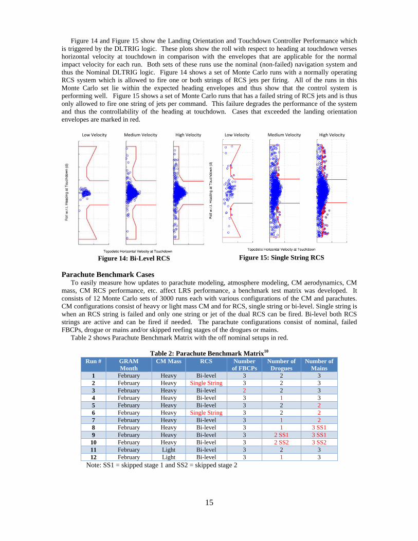
Figure 14 and Figure 15 show the Landing Orientation and Touchdown Controller Performance which is triggered by the DLTRIG logic. These plots show the roll with respect to heading at touchdown verses horizontal velocity at touchdown in comparison with the envelopes that are applicable for the normal impact velocity for each run. Both sets of these runs use the nominal (non-failed) navigation system and thus the Nominal DLTRIG logic. Figure 14 shows a set of Monte Carlo runs with a normally operating RCS system which is allowed to fire one or both strings of RCS jets per firing. All of the runs in this Monte Carlo set lie within the expected heading envelopes and thus show that the control system is performing well. Figure 15 shows a set of Monte Carlo runs that has a failed string of RCS jets and is thus only allowed to fire one string of jets per command. This failure degrades the performance of the system and thus the controllability of the heading at touchdown. Cases that exceeded the landing orientation envelopes are marked in red. Low Velocity Medium Velocity High Velocity
Figure 14: Bi-Level RCS
Low Velocity Medium Velocity High Velocity
Figure 15: Single String RCS
Parachute Benchmark Cases
To easily measure how updates to parachute modeling, atmosphere modeling, CM aerodynamics, CM mass, CM RCS performance, etc. affect LRS performance, a benchmark test matrix was developed. It consists of 12 Monte Carlo sets of 3000 runs each with various configurations of the CM and parachutes. CM configurations consist of heavy or light mass CM and for RCS, single string or bi-level. Single string is when an RCS string is failed and only one string or jet of the dual RCS can be fired. Bi-level both RCS strings are active and can be fired if needed. The parachute configurations consist of nominal, failed FBCPs, drogue or mains and/or skipped reefing stages of the drogues or mains.
Table 2 shows Parachute Benchmark Matrix with the off nominal setups in red.
Table 2: Parachute Benchmark Matrix10 Run # GRAM
Month CM Mass RCS Number
of FBCPs Number of
Drogues Number of
Mains 1 February Heavy Bi-level 3 2 3 2 February Heavy Single String 3 2 3 3 February Heavy Bi-level 2 2 3 4 February Heavy Bi-level 3 1 3 5 February Heavy Bi-level 3 2 2 6 February Heavy Single String 3 2 2 7 February Heavy Bi-level 3 1 2 8 February Heavy Bi-level 3 1 3 SS1 9 February Heavy Bi-level 3 2 SS1 3 SS1
10 February Heavy Bi-level 3 2 SS2 3 SS2 11 February Light Bi-level 3 2 3 12 February Light Bi-level 3 1 3
Note: SS1 = skipped stage 1 and SS2 = skipped stage 2

16
Figure 16 is a co-plot of the vertical velocity at touchdown verses the Monte Carlo run number for cases from the Parachute Benchmark Matrix Runs #1 (blue) and #5 (red). As expected the results with three good main parachutes have a lower touchdown velocity that those runs with two good main parachutes. If the parachutes failed to fully inflate or were not deployed in time then the touchdown velocity would be exceedingly high. All of these runs successfully deployed the main parachutes.
Figure 17 is a co-plot of the altitude at which the FBC Parachutes were deployed using the Nominal
DLTRIG FSW verses the Monte Carlo run number. The navigation system is setup without failures for these simulations. Blue data points are from the Parachute Benchmark Matrix Run #1 which has a fully functional RCS system; while the red data points are from Run #2 which has a failed string of RCS jets. The data indicates that all the runs in both sets deployed the FBC Parachutes between the floor and ceiling of the deploy box. A few runs with Bi-level RCS triggered the deployment using the Smart FBC Chute Deploy logic due to high vehicle pitch/yaw rates, while the vast majority of the runs were able to deploy the FBCPs at the Floor of the window as expected. The Single String RCS runs showed significantly more cases where the rates were high enough to trigger the FBC Chute Deploy logic above the floor (the majority of the runs triggered at the floor altitude). All of these runs are greatly affected by the aerodynamics of the vehicle and the effectiveness of the RCS system.
Figure 16: Vertical Velocity at Touchdown for 2 and 3 Main Parachutes
Figure 17: Altitude at FBC Chute Deploy for Bi-Level and Single String RCS
LESSONS LEARNED
Due to system constraints, CM aerodynamics, parachute configuration, etc. it appears unlikely to develop a SDR algorithm that can eliminate all flips of the CM during main parachute deployment for one drogue situations.
High CM rates underneath one drogue parachute are a consequence of choosing a single point
attachment configuration for the drogues versus a three point harness system with a confluence fitting for the drogue risers. The single attach point was selected because it was less complicated to rig, had lower volume requirements, was easier to pack under the FBC and was less likely to foul during deployment than the harness system.

17
CONCLUSIONS
The Descent and Landing Triggers Flight Software continues to evolve and improve with every update of the Orion MPCV Flight Software. Updates and improvements in the teams understanding of the navigation systems, aerodynamics, parachute systems, control systems and atmosphere greatly influence the design and trigger selections for the DLTRIG FSW. The current design has been thoroughly tested and inspected and it is ready for the Exploration Flight Test-1 mission. FUTURE UPDATES
The DLTRIG FSW will be updated for future Orion MPCV mission requirements including Ascent aborts and manual crew inputs. Lessons learned from the EFT-1 mission and ongoing CPAS drop tests will provide opportunities to enhance and upgrade the FSW.
The incorporation of a third string of GPS on future missions may allow the removal of the Velocity
Trigger as a backup for the FBC Jettison. Low altitude Ascent aborts such as an engine out on the launch pad may result in skipping the drogue
parachutes and go straight to the main parachutes. One option for improving SDR is switching SDR to monitor total rotational energy instead of rates and
trigger drogue release on minimum energy. Another option is to investigate changing SDR to monitor the angle between the rate vector and hang angle vector and have SDR command release at a minimum of this angle. This may work because it could have the drogues released at the smallest possible delta from alpha total trim angle, resulting in the lowest possible aerodynamic moments acting on the CM during main deploy.
With the use of off the shelf tools like the MATLAB® suite, these updates will be simple to implement,
configure, test and analyze. ACKNOWLEDGMENTS
The authors would like to acknowledge all of the members of the MPCV Flight Dynamics Team, with specific thanks to the members of the: Orion Entry MODE Team, Orion GN&C Flight Software Team, the Integration and Test MODE Team, the Descent and Landing Working Group, the Capsule Parachute Assembly System Team, the MPCV Aerosciences Team, and the Orion Absolute Navigation Team.
Individual contributors include: Chris Madsen/NASA, Roger Wacker/Honeywell, Brian Hoelscher/NASA, David Shoemaker/LM, Mark Kane/NASA, Brian Neumann/Jacobs Technology, Andrew Barth/LM, Susan Stachowiak/NASA, Joy King/USA, Robert Gay/NASA, Deborah Merritt/NASA, Jeremy Rea/NASA, James Dearman/LM, Dustin Neill/LM, Peter Cuthbert/NASA, Greg Loe/HI, Jared Daum/NASA, Mark McPherson/NASA, Daniel Matz/NASA, Chris Prouty/LM, Joe Gamble/MEI, Christopher Johnson/NASA, Phil Robinson/NASA, James Thompson/ERC, Luke McNamara/NASA, Sarah McNamara/NASA, Gavin Mendeck/NASA, William Pratt/LM, Chris Salerno/LM, Michael Frostad/ERC, James DeRubeis/Jacobs, Dennis Keller/Jacobs, Jessamyn Davis/ERC, Ricardo Machin/NASA, Patrick Galvin/ERC, Eric Ray/Jacobs, Leah Romero/Jacobs, Howard Hu/NASA, Timothy Straube/NASA, Ryan Proud/NASA, Daniel Kubitschek/LM, Mike Hughes/LM, and Michael Begley/LM. All images and photos provided by NASA, Lockheed Martin or Honeywell.

18
REFERENCES
1 National Aeronautics and Space Administration. Orion Exploration Flight Test 1 (NASA Publication No. FS-2012-05-018-JSC). 2012, Retrieved from http://www.nasa.gov. 2 Johnson, C., Hixson, R., AIAA 2008-7745. Orion Vehicle Descent, Landing, and Recovery Systems Level Trades, September 2008.
3 Neill, D., Orion: ADS Evolution Card. Sept 2010.
4 Lockheed Martin Space Systems Company. CEV-T-078002, Orion Project Guidance Navigation and Control Data Book, Volume 4: Guidance System Design, Change Legend: 001, March 23, 2012. 5 Lockheed Martin Space Systems Company. CEV-GNC-11-049, GDE_DescentAndLandingTriggers_CSU_Memo, Revision 7.2, October 24, 2012.
6 Barth, Andy. CEV-GN&C-12-047. Smart Drogue Release Issues in BL9.0. October 18, 2012.
7 Hughes, M., Energy Methods for Optimal Dynamic Stage Handover. November 6, 2012. 8 Hughes, M., Gamble, J., First Principles CM Stability. Parts 1 and 2. Descent and Landing Working Group charts, August 14, 2012 9 Lockheed Martin Space Systems Company. CEV-T-005000, Project Orion Software Development Plan Volume 0. Change Legend: 003. September 30, 2009. 10 Lockheed Martin Space Systems Company. LM-ORN-0598. Parachute Systems Model Parameters v11.0. Revision: 002. December 5, 2012.