
Desaireador de Air Release Head - IO
14
Issue/Rev. 0.0 (3/11) Bulletin MN03022 The Most Trusted Name In Measurement Installation/Operation DE Air Release Head Contents Section 1 – Introduction ............................................................................................................................. Page 2 Receipt of Equipment ..................................................................................................................................... Page 2 Principal of Operation .............. ....................................................................................................................... Page 2 Section 2 – Installation .............................................................................................................................. Page 5 Mechanical (DE-1 and DE-2 General) ............................................................................................................ Page 6 Electrical – 120 Vac ............. ........................................................................................................................... Page 7 Electrical – 12 or 24 Vdc ................................................................................................................................. Page 8 Electrical – 240 Vac ............. ........................................................................................................................... Page 8 Section 3 – Start Up ................................................................................................................................. Page 11 DE-1 and DE-2 with 200 Series Valv e ....... ................................................................................................... Page 11 Section 4 – T roubleshooting ..................................................................................................................... Page 12 Preventativ e Maintenance ............................................................................................................................ Page 12 Section 5 – Related Publications ............................................................................................................ Page 14 Smith Meter ® Release Head
-
Upload
camilo-barrera -
Category
Documents
-
view
218 -
download
0
Transcript of Desaireador de Air Release Head - IO

7/21/2019 Desaireador de Air Release Head - IO
http://slidepdf.com/reader/full/desaireador-de-air-release-head-io 1/14
Issue/Rev. 0.0 (3/11) Bulletin MN03022
The Most Trusted Name In Measurement
Installation/Operation
DE Air Release Head
Contents
Section 1 – Introduction ............................................................................................................................. Page 2
Receipt of Equipment ..................................................................................................................................... Page 2
Principal of Operation ..................................................................................................................................... Page 2
Section 2 – Installation .............................................................................................................................. Page 5
Mechanical (DE-1 and DE-2 General) ............................................................................................................ Page 6
Electrical – 120 Vac ........................................................................................................................................ Page 7
Electrical – 12 or 24 Vdc ................................................................................................................................. Page 8
Electrical – 240 Vac ........................................................................................................................................ Page 8
Section 3 – Start Up ................................................................................................................................. Page 11
DE-1 and DE-2 with 200 Series Valve .......................................................................................................... Page 11
Section 4 – Troubleshooting ..................................................................................................................... Page 12
Preventative Maintenance ............................................................................................................................ Page 12
Section 5 – Related Publications ............................................................................................................ Page 14
Smith Meter ® Release Head

7/21/2019 Desaireador de Air Release Head - IO
http://slidepdf.com/reader/full/desaireador-de-air-release-head-io 2/14
Issue/Rev. 0.0 (3/11)Page 2 •
MN03022
Receipt of Equipment
When the equipment is received, the outside packingcase should be checked immediately for any shippingdamage. If the packing case has been damaged, thelocal carrier should be notified at once regarding his
liability. Carefully remove the unit from its packing caseand inspect for damaged or missing parts.
If damage has occurred during shipment or parts aremissing, a written report should be submitted to theCustomer Service Department, FMC TechnologiesMeasurement Solutions, Inc., Erie, Pennsylvania,16514-0428.
Prior to installation, the unit should be stored in its origi-nal packing case and protected from adverse weatherconditions and abuse.
Principle of Operation
The Smith Meter Model DE (Dual Electric) Air ReleaseHead is a float switch operated air release head. Theair release head upon sensing the presence of air in aliquid system, simultaneously opens an integral air ventsolenoid valve and signals a control valve downstreamof the meter to close. After the sensed air has beenexhausted (into a drain system or into tankage), the in-tegral air vent solenoid valve closes and the downstreamcontrol valve is allowed to reopen. Dual floats locatedin the air eliminator tank control the operation of the airrelease and the control valve. Detection of air at the
lower float begins the exhaust cycle and valve closurewhich is maintained until the upper float detects productand terminates the exhaust cycle and resumes flow.
The sequence of operation is as follows:
As the liquid level in the tank drops, the electricallycontrolled block valve is allowed to remain open, permitting
flow, until the liquid level drops below the "low" liquidlevel line. As the lower float drops, a switch is trippedinterrupting the electrical power to the valve controlsolenoid, thereby, closing the main valve and stoppingproduct flow. This same switch, by means of the relayslocated in the DE Head junction box, also opens thenormally closed solenoid valve mounted on the air ventport of the DE Air Release, permitting the air trappedwithin the vessel to be vented.
As the trapped air is vented and is replaced by liquid,the valve control solenoid remains closed until the liq-uid rises to the "high" liquid level line, raising the upperfloat, tripping a second switch. This action de-energiz-es (closes) the solenoid valve on the air vent port, and
simultaneously re-energizes the valve control solenoidpermitting the main valve to reopen (Figures 1 and 2).
Figure 1 – Smith Meter Model DE-1 with 200-30A Block Valve in Open Position
Section 1 – Introduction

7/21/2019 Desaireador de Air Release Head - IO
http://slidepdf.com/reader/full/desaireador-de-air-release-head-io 3/14
Issue/Rev. 0.0 (3/11) MN03022•
Page 3
Figure 2 – Smith Meter Model DE-2 with 202 Bare Valve in Open Position
Section 1 – Introduction
7/21/2019 Desaireador de Air Release Head - IO
http://slidepdf.com/reader/full/desaireador-de-air-release-head-io 4/14
Issue/Rev. 0.0 (3/11)Page 4 •
MN03022
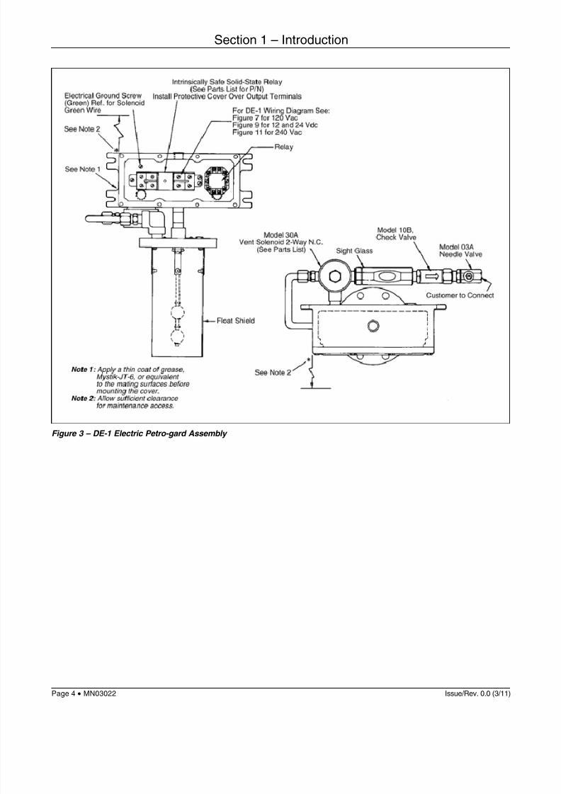
Figure 3 – DE-1 Electric Petro-gard Assembly
Section 1 – Introduction
7/21/2019 Desaireador de Air Release Head - IO
http://slidepdf.com/reader/full/desaireador-de-air-release-head-io 5/14
Issue/Rev. 0.0 (3/11) MN03022•
Page 5
Electrical Ground Screw(Green) Ref. for SolenoidGreen Wire
See Note 2
*
See Note 1
Intrinsically Safe Solid-State Relay(See Parts List for P/N)
Install Protective Cover Over Output Terminals
For DE-2 Wiring Diagram See:Figure 8 for 120 Vac
Figure 10 for 12 and 24 Vdc
Figure 12 for 240 Vac Relay
Housing
MountingFlange
SwitchAssembly
FloatShield
Sight Glass
Model 30A Solenoid2-Way N.C.
*See Note 2
Model 31A Solenoid2-Way N.O.
Model 10B,Check Valve
Model 03A,Ball Valve
Model 13FCustomerto Connect(3/8" NPT)
Note 1: Apply a thin coat of grease, Mystik-JT-6, or equivalent to the mating surfaces before mounting the cover.Note 2: Allow sufficient clearance for maintenance access.
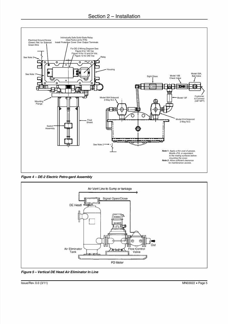
Figure 4 – DE-2 Electric Petro-gard Assembly
Figure 5 – Vertical DE Head Air Eliminator In Line
Section 2 – Installation

7/21/2019 Desaireador de Air Release Head - IO
http://slidepdf.com/reader/full/desaireador-de-air-release-head-io 6/14
Issue/Rev. 0.0 (3/11)Page 6 •
MN03022
Figure 6 – DE Head Air Eliminator In Line
Figure 7 – DE-1 120 Vac
Mechanical (DE-l and DE-2 General)
Field Installation on Existing Air Eliminators
1. On vertical tanks, remove the existing air releasehead. On horizontal tanks, remove the most downstream head and thoroughly clean the surface towhich the DE Head will be mounted. (Remove oldgasket material, etc.) For multiple head arrangements,install blind flanges or plug air release outlet in placeof existing RB heads.
2. Install the new gasket that is supplied with the DE Head.
3. Be sure that the floats on the liquid level switchassembly travel freely throughout the range asdetermined by the tank size (Figure 6).
4. Insert the assembly into the tank. Be sure that thestem assembly is vertical and that the junction boxcover is accessible. Provide sufficient clearance formaintenance access (Figures 3 and 4).
5 Bolt the DE Head Assembly to the previously preparedflange using the bolts supplied.
6 Proceed to the next section appropriate to yourinstallation.
Section 2 – Installation

7/21/2019 Desaireador de Air Release Head - IO
http://slidepdf.com/reader/full/desaireador-de-air-release-head-io 7/14
Issue/Rev. 0.0 (3/11) MN03022•
Page 7
DE-1 with 200 Series Valve
1. Install the Smith Meter Model 200-30A Valve into the line.Be sure the directional flow arrow on the valve bodyagrees with the product flow direction.
2. Connect the sight glass, check valve, and ball valveassembly (Figure 3) to the 30A Solenoid. Connect the
air exhaust line, pipe or tubing from the 03A Ball Valveto the downstream side of the valve or downstreamof the prover loop (3/8" O.D. on 3",4", or 6" systems,1/2" O.D. on 8",10", or 12" systems).
DE-2 with 200 Series Valve
1. Install the Smith Meter Model 202 into the line. Orientthe valve cover in a horizontal position.
Be sure that the flow arrow on the valve body agreeswith the product flow direction. Remove the plug fromthe valve cover. Fill the cover to overflowing withproduct, light machine oil, or hydraulic transmissionfluid to minimize air entrapment. Reinstall the valve
cover plug.2. Install pipe or tubing (3/8" O.D. minimum) from the
Model 31A Solenoid Port No.1, to the control valvecover.
3. Install the air release line to the downstream port ofthe valve or downstream of the prover loop to the tankreturn (3/8" O.D. on 3", 4", or 6" systems, 1/2" O.D. on8",10", or 12" systems).
Note: The 10B Check Valve on the air release line of the DE-1 andDE-2 is for anti-siphone and should not be removed.
Electrical – 120 Vac
DE-1 with 200 Series Valve
1. Connect the main shutoff (N.O.) between the acsupply L1 and Input Terminal 2 of the intrinsically safesolid-state relay (Figure 7). AWG 18 minimum wire
size is recommended for all connections.2. Connect AC supply neutral to Terminal 1 on the
intrinsically safe solid-state relay.
3. See Figure 7 for connections to solenoids and thecontrol valve.
4. Use ohm meter to test that both float contacts to theintrinsically safe solid-state relay are normally closed(with tank dry). Test between Terminals 8 and 5 withTerminal 7 common.
DE-2 with 200 Series Valve
1. Connect pump control relay contacts (N.O.) betweenAC Supply L 1 and Input Terminal 2 of intrinsicallysafe solid-state relay (Figure 8). AWG 18 minimumwire size recommended for all connections.
2. Connect AC supply neutral to Terminal 1 of theintrinsically safe solid-state relay.
3. See Figure 8 for connections to Intrinsic safetydevices and relay connections to solenoids.
4. Use an ohm meter to test that both float contacts tothe intrinsically safe solid-state relay are: normallyclosed (with tank dry). Test between Terminals 8 and5 with Terminal 7 common.
Figure 8 – DE-2 120 Vac
Section 2 – Installation

7/21/2019 Desaireador de Air Release Head - IO
http://slidepdf.com/reader/full/desaireador-de-air-release-head-io 8/14
Issue/Rev. 0.0 (3/11)Page 8 •
MN03022
Electrical – 12 or 24 Vdc
DE-1 and DE-2 with 200 Series Valve
1. Connect pump control relay contacts (N.O.) betweendc supply voltage and input supply positive (+)terminal of intrinsically safe solid-state relay. AWG
18 minimum wire size is recommended for allconnections.
2. See Figures 9 and 10 for voltage connections to theintrinsically safe solid-state relay and the relayconnections to solenoids.
3. Test to be sure that both float contacts to intrinsicallysafe solid-state relay are normally closed (with tankdry) between the terminals of each intrinsically safesolid-state relay designated switch input. Be surethat the connections are made according to Figure 9or Figure 10.
12 Vdc, 1.8AOptional: 24 Vdc, 0.9A
Recommended Main Shutoff
(+)(-)
(-) (+)
(-) (+)
2 7
R1
Load
RedLeads
Intrinsically SafeSolid-State Relay
Switch
Bottom Float
Intrinsically SafeSolid-State Relay
Switch
See Note 3
Shutoff ValveSolenoid
VentSolenoid
Load
YellowLeads
Top Float
R1B
R1A
14
3
5
6
8
Caution
If the DE Head is used inapplications where the polarity of the supply voltage (DC) canbe reversed, a protective network is required (optional).
Note:
1. Float switches are closed in down (dry) position.2. Relay: 12V DPDT or 24V DPDT or equivalent.3. RC Network:
P/N 645060-4-03. RG 1986-6. 0.5 uf. 100 Ω (2 required).4. Use 18 gauge minimum wire size.5. Schematic shown not energized.
Customerto Install
Customer to Connect 2-Way N.C.
2-Way N.C.
Figure 9 – DE-1 - 12/24 Vdc
Electrical – 240 Vac
DE-1 and DE-2 with 200 Series Valve
1. Connect pump control relay contacts, Figures 11and 12, (N.O.) between AC supply L 1 and Vac input12 Vdc 1.8A terminal to intrinsically safe solid-state
relay. AWG 18 minimum wire size is recommendedfor all connections. Connect L2 to the other Vacterminal.
2. See Figure 11 (DE-1) and Figure 12 (DE-2) forconnections to the intrinsically safe solid-state relayand the solenoids on the control valve.
3. Test to be sure that both float contacts to intrinsicallysafe solid-state relay are normally closed (with tankdry) between terminals on and off. Test with top float(yellow wires) connected between common and offterminals and bottom float (red wires) connectedbetween common and on terminals.
Grounding Be sure the power ground (green) wire from the sole-noids and AC power ground (green wire) are connectedto the grounding screw in the explosion proof junctionbox.
Section 2 – Installation

7/21/2019 Desaireador de Air Release Head - IO
http://slidepdf.com/reader/full/desaireador-de-air-release-head-io 9/14
Issue/Rev. 0.0 (3/11) MN03022•
Page 9
12 Vdc, 3.5AOptional: 24 Vdc, 1.8A
(+)(-)
(-) (+)
(-) (+)
2 7
R1
Load
RedLeads
Intrinsically SafeSolid-State Relay
Switch
Bottom Float
Intrinsically SafeSolid-State Relay
Switch
See Note 3
Valve ControlSolenoid
VentSolenoid
Load
YellowLeads
Top Float
R1B
R1A
14
3
5
6
8
Caution
If the DE Head is used inapplications where the polarity of the supply voltage (DC) canbe reversed, a protective network is required (optional).
Note:
1. Float switches are closed in down (dry) position.2. Relay: 12V DPDT or 24V DPDT or equivalent.3. RC Network: P/N 645060-4-03. RG 1986-6. 0.5 uf. 100 Ω (2 required).4. Use 18 gauge minimum wire size.5. Schematic shown not energized.
Recommended Main Shutoff
Customerto Install
3-Way N.O.
2-Way N.C.
Figure 10 – DE-2 - 12/24 Vdc
Figure 11 – DE-1 - 240 Vdc
Section 2 – Installation

7/21/2019 Desaireador de Air Release Head - IO
http://slidepdf.com/reader/full/desaireador-de-air-release-head-io 10/14
Issue/Rev. 0.0 (3/11)Page 10 •
MN03022
Figure 12 – DE-2 - 240 Vac
Section 2 – Installation

7/21/2019 Desaireador de Air Release Head - IO
http://slidepdf.com/reader/full/desaireador-de-air-release-head-io 11/14
Issue/Rev. 0.0 (3/11) MN03022•
Page 11
DE-1 and DE-2 with 200 Series Valve
1. Fill the system by gravity to check for leaks and toprevent line shock during start-up.
2. Bleed all air from the valve, meter, and strainer as thesystem is filled with product. Close all exhaust ports
as the system is filled.3. Turn power "on" to system.
4. Consider the air eliminator tank to have entrapped air.
a. Open ball valves on DE-1 and DE-2 fully.
b. Jog the pump and check that air is evacuated and thatthe valve remains closed at this time.
c. Be sure that after air is evacuated the valve opens.As the valve opens, the pump can be left on. No solidstream of product should be seen in the sight glass.Shut the system down if this occurs.
d. If the control valve does not open or the sight glassfills with product, refer to the Troubleshooting Sectionof this manual.
Section 3 – Start Up

7/21/2019 Desaireador de Air Release Head - IO
http://slidepdf.com/reader/full/desaireador-de-air-release-head-io 12/14
Issue/Rev. 0.0 (3/11)Page 12 •
MN03022
Preventative Maintenance
1. High paraffin base crude or products with sedimentmay plug the solenoid orifice or seats, monitor forcorrect operation, flush or wash as needed.
2. Water in product at freezing temperature will solidify
and cause the orifice valve or check valves to jam.Clean or apply heat as required to release them.
3. Waxy crudes may coat the stem assembly of the DEHead floats and require periodic cleaning.
4. Base maintenance and/or cleaning schedules ofstrainers on a prior history of product requirements.
Warning
Remove the DE Head to a non-hazardous area fortroubleshooting after removing power from the unit.
Symptom Cause Corrective Action
No flow. No pump pressure.
No power.
Pump permissive contact open.
Control valve not opening.
Float switches (N.C.) dry, not opening astank fills.
Intrinsically safe solid-state relay defective.
Relay defective.
Valve control solenoids not operating.
Main control valve diaphragm defective.
Fixed orifice 13F plugged (DE-2 Head only).
Turn pump on.
Check for power to input.
Confirm pump contact (N.O.).
Close and apply power to the DE Head.
Check operation of float switches with voltohm meter (VOM) or multimeter as they are
moved. See correct schematic figures.With both float switches closed, the activevoltage should be on Relay Terminal 7common. If not, intrinsically safe solid-staterelay is defective – replace.
If active, voltage is between Terminals 2and 7 of the relay. The relay should activate,if not, replace
Check power wiring from DE Head. With nopower to unit, check continuity of solenoidand resistance of coil to ground for open orleakage. Typical coil resistance is less than500 Ω. Leakage not less than 10 kΩ hot.
Note: Check for debris in valve body ifelectrically correct.
If valve diaphragm is defective, pressure
is equalized (no differential), valve will notopen. Check or replace as needed.
Clean as required.
Control valve not opening. 03A Ball Valve on DE-2 not open. Open Ball Valve.
Product in sight glass. 30A Solenoid open.
Floats jammed (down position or leaking).
Intrinsic barrier defective.
10B Check Valve defective.
Relay defective.
Check for debris, clean as needed.
Check floats, high paraffin base crude willcause build up; clean as required.
Check barrier float, input contacts, andwiring with tank filled float switches open.Replace or correct as required.
Test 10B Valve for one-way flow, clean orreplace as required.
With floats in upper position, the relay shouldbe inactive – no voltage to Relay Terminal 2.Repair or replace as required.
Main control valve not closing(continuous flow).
Control Valve Solenoid 30A or 31malfunction.
Debris lodged under main valve poppet.
Floats jammed up.
Power to control solenoid not disabled.
Check operation of solenoid. Parts shouldclose with no power; clean and/or replace asrequired.
Isolate valve, check for leakage.
Clean/repair as required.
Check floats, high paraffin base crude willcause a build up, clean as required.
Test intrinsically safe solid-safe relay forcorrect operation with control valve. Repair/ replace as required.
Section 4 – Troubleshooting
7/21/2019 Desaireador de Air Release Head - IO
http://slidepdf.com/reader/full/desaireador-de-air-release-head-io 13/14
Issue/Rev. 0.0 (3/11) MN03022•
Page 13
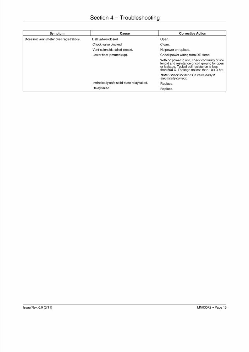
Symptom Cause Corrective Action
Does not vent (meter over registration). Ball valves closed.
Check valve blocked.
Vent solenoids failed closed.
Lower float jammed (up).
Intrinsically safe solid-state relay failed.
Relay failed.
Open.
Clean.
No power or replace.
Check power wiring from DE Head.
With no power to unit, check continuity of so-lenoid and resistance or coil ground for openor leakage. Typical coil resistance is lessthan 500 Ω. Leakage no less than 10 kΩ hot.
Note: Check for debris in valve body ifelectrically correct.
Replace.
Replace.
Section 4 – Troubleshooting

7/21/2019 Desaireador de Air Release Head - IO
http://slidepdf.com/reader/full/desaireador-de-air-release-head-io 14/14
The following literature can be obtained from FMC Technologies Measurement Solutions, Inc. Literature Fulfillmentat [email protected] or online at www.fmctechnologies.com/measurementsolutions . When requesting literature fromLiterature Fulfillment, please reference the appropriate bulletin number and title.
DE-1 and DE-2
Specifications ................................................................................................................................. Bulletin SS03030
Parts List.........................................................................................................................................Bulletin P0100.xx
Visit our website at www.fmctechnologies.com/measurementsolutions
The specifications contained herein are subject to change without notice and any user of said specifications should verify from the manufacturer that the specifications are currentlyin effect. Otherwise, the manufacturer assumes no responsibility for the use of specifications which may have been changed and are no longer in effect.
Contact information is subject to change. For the most current contact information, visit our website at www.fmctechnologies.com/measurementsolutions and click on the“Contact Us” link in the left-hand column.
Headquarters:500 North Sam Houston Parkway West, Suite 100, Houston, TX 77067 USA, Phone: +1 (281) 260 2190, Fax: +1 (281) 260 2191
Measurement Products and Equipment:Erie, PA USA +1 (814) 898 5000
Ellerbek, Germany +49 (4101) 3040
Barcelona, Spain +34 (93) 201 0989
Beijing, China +86 (10) 6500 2251
Buenos Aires, Argentina +54 (11) 4312 4736
Burnham, England +44 (1628) 603205
Dubai, United Arab Emirates +971 (4) 883 0303
Los Angeles, CA USA +1 (310) 328 1236Melbourne, Australia +61 (3) 9807 2818
Moscow, Russia +7 (495) 5648705
Singapore, +65 6861 3011
Thetford, England +44 (1842) 822900
Integrated Measurement Systems: Corpus Christi, TX USA +1 (361) 289 3400
Kongsberg, Norway +47 (32) 286700
Dubai, United Arab Emirates +971 (4) 883 0303
MN03022 Issue/Rev. 0.0 (3/11): Replaces MN01024X. All Figures have been updated.
Section 5 – Related Publications


![IO [Inorganic] Compendium Method IO-3.4: Determination of ...](https://static.fdocuments.in/doc/165x107/61bd108661276e740b0efce1/io-inorganic-compendium-method-io-34-determination-of-.jpg)


