DER Interconnection Requirements - National Renewable … · · 2017-02-16Technical Leader,...
21
© 2015 Electric Power Research Institute, Inc. All rights reserved. Aminul Huque, PhD Technical Leader, Integration of DER, Electric Power Research Institute Integrating PV in Distribution Grids: Solutions and Technologies Workshop Energy Systems Integration, NREL Golden, CO; October 23, 2015 DER Interconnection Requirements Need for Harmonization
Transcript of DER Interconnection Requirements - National Renewable … · · 2017-02-16Technical Leader,...

© 2015 Electric Power Research Institute, Inc. All rights reserved.
Aminul Huque, PhDTechnical Leader, Integration of DER, Electric Power Research Institute
Integrating PV in Distribution Grids: Solutions and Technologies WorkshopEnergy Systems Integration, NREL
Golden, CO; October 23, 2015
DER Interconnection Requirements
Need for Harmonization
2© 2015 Electric Power Research Institute, Inc. All rights reserved.
Presentation Outline
IEEE 1547a‐2014
Opportunities & flexibilities
IEEE 1547‐201X: Full Revision
Approach
Can it bring the harmony back
3© 2015 Electric Power Research Institute, Inc. All rights reserved.
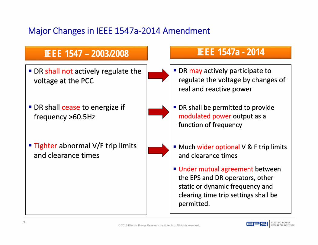
IEEE 1547 – 2003/2008 DR shall not actively regulate the voltage at the PCC
DR shall cease to energize if frequency >60.5Hz
Tighter abnormal V/F trip limits and clearance times
DR shall not actively regulate the voltage at the PCC
DR shall cease to energize if frequency >60.5Hz
Tighter abnormal V/F trip limits and clearance times
IEEE 1547a - 2014
DR may actively participate to regulate the voltage by changes of real and reactive power
DR shall be permitted to provide modulated power output as a function of frequency
Much wider optional V & F trip limits and clearance times
Under mutual agreement between the EPS and DR operators, other static or dynamic frequency and clearing time trip settings shall be permitted.
Major Changes in IEEE 1547a‐2014 Amendment

4© 2015 Electric Power Research Institute, Inc. All rights reserved.
Changes in “Response to Abnormal Voltages”
IEEE 1547-2003/2008
IEEE 1547a - 2014
5© 2015 Electric Power Research Institute, Inc. All rights reserved.
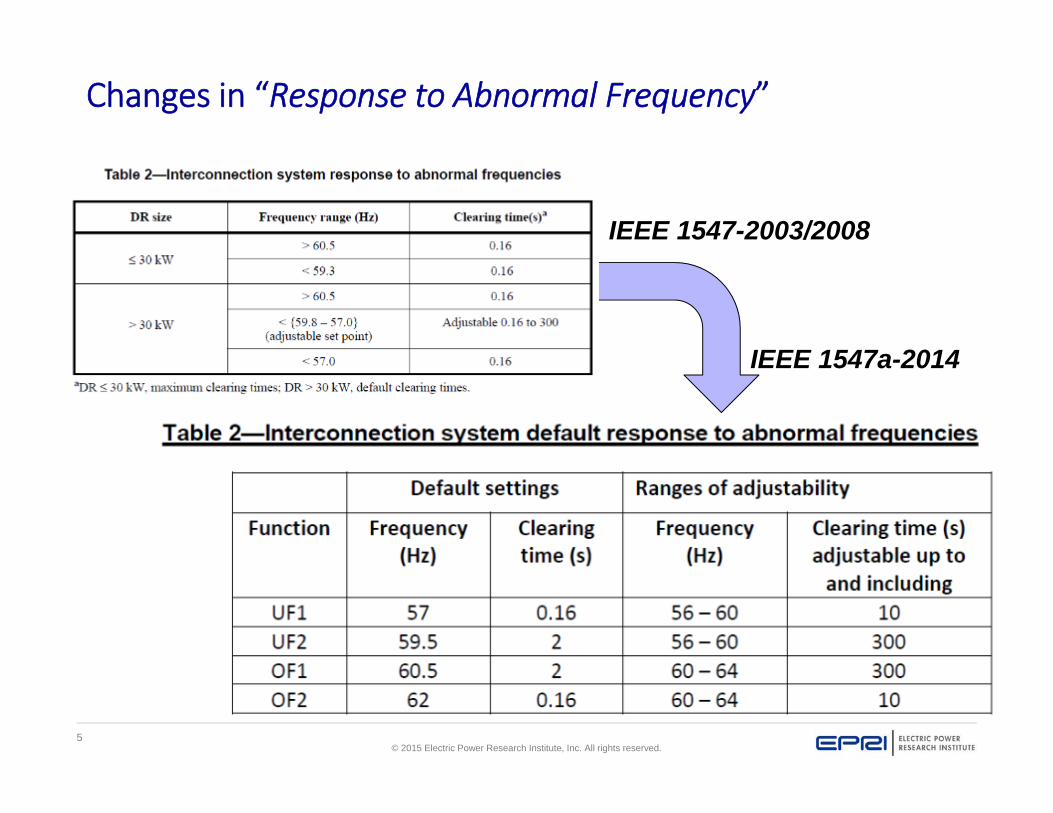
Changes in “Response to Abnormal Frequency”
IEEE 1547-2003/2008
IEEE 1547a-2014
6© 2015 Electric Power Research Institute, Inc. All rights reserved.
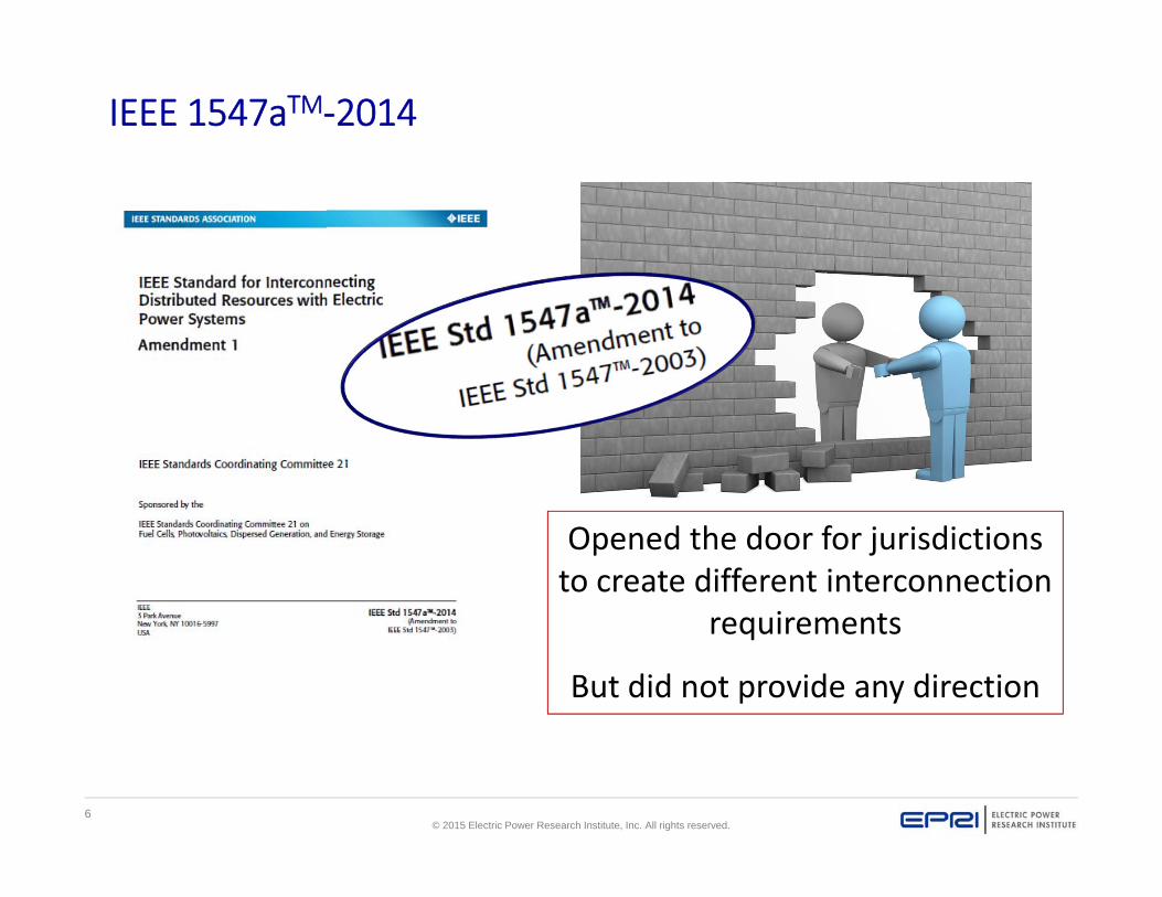
IEEE 1547aTM‐2014
Opened the door for jurisdictions to create different interconnection
requirements
But did not provide any direction
7© 2015 Electric Power Research Institute, Inc. All rights reserved.
NY SIR
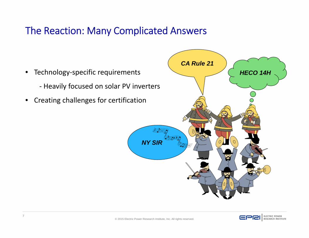
The Reaction: Many Complicated Answers
• Technology‐specific requirements
‐ Heavily focused on solar PV inverters
• Creating challenges for certification
CA Rule 21HECO 14H

8© 2015 Electric Power Research Institute, Inc. All rights reserved.
NY State Standardized Interconnection Requirements (SIR)
Under Consideration !
For inverters rated at 250 kW and above shall be equipped with static VAR control (need harmonization in function names) as standard functionality. Settings shall be reviewed and approved by the utility during the application process and shall not be adjusted by the generator-owner after system installation and verification testing.
All inverters shall include frequency and ride through functionalities as documented in IEEE 1547a…(the 1547a allow, but doesn’t define ride-thru)
Inverters shall be upgradeable with firmware for dynamic power factor control (need harmonization in function names)
If deemed necessary due to abnormal system conditions the utility may request that the generator operate at frequency ranges below 59.3 Hz in coordination with the load shedding schemes of the utility system
The utility reserves the right to reject system designs where multiple inverters with different manufacturers are used, where the conflicts between various anti-islanding algorithms is of concern
9© 2015 Electric Power Research Institute, Inc. All rights reserved.
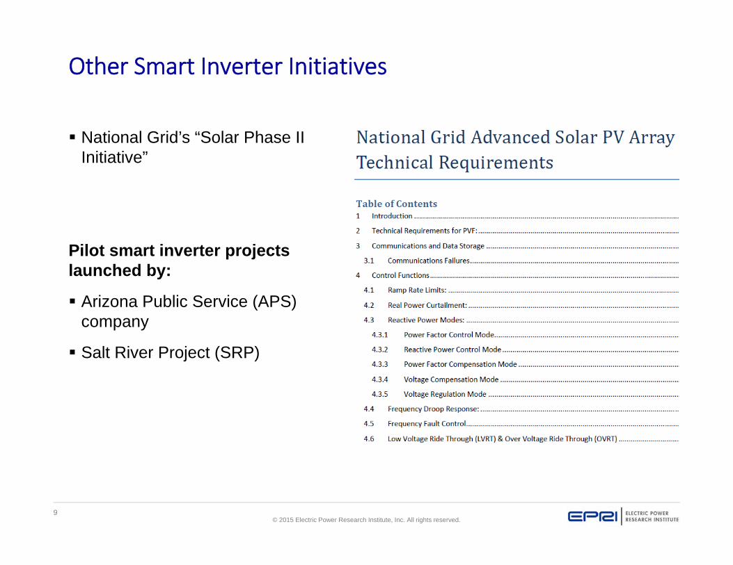
Other Smart Inverter Initiatives
National Grid’s “Solar Phase II Initiative”
Pilot smart inverter projects launched by:
Arizona Public Service (APS) company
Salt River Project (SRP)
10© 2015 Electric Power Research Institute, Inc. All rights reserved.
Presentation Outline
IEEE 1547a‐2014
Opportunities & flexibilities
IEEE 1547‐201X: Full Revision
Approach
Can it bring the harmony back
11© 2015 Electric Power Research Institute, Inc. All rights reserved.
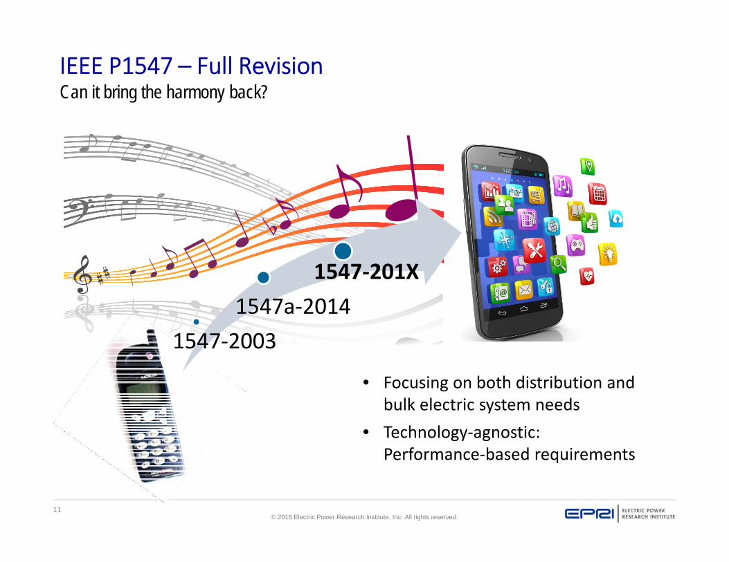
IEEE P1547 – Full RevisionCan it bring the harmony back?
• Focusing on both distribution and bulk electric system needs
• Technology‐agnostic: Performance‐based requirements
1547‐20031547a‐2014
1547‐201X
12© 2015 Electric Power Research Institute, Inc. All rights reserved.
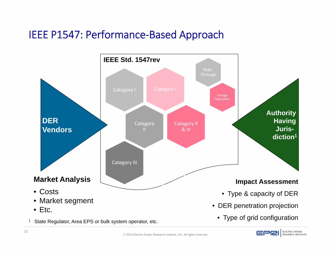
IEEE Std. 1547rev
IEEE P1547: Performance‐Based Approach
Category ICategory I
Category II
Category II & III
Category III
DERVendors
Authority Having Juris-
diction1
Ride‐Through
VoltageRegulation
1 State Regulator, Area EPS or bulk system operator, etc.
Impact Assessment
• Type & capacity of DER
• DER penetration projection
• Type of grid configuration
Market Analysis• Costs• Market segment• Etc.

13© 2015 Electric Power Research Institute, Inc. All rights reserved.
General Requirement 1: Voltage Regulation Approach(Work‐in‐Progress)
Other reactive and real power control modes and implementations shall be permitted under mutual agreement between the EPS and DER operators.
4.1 General requirements
4.1.1 Reactive Power Capability of the DER
4.1.2 Voltage and Reactive Power Control
4.1.2.1 Power Factor Mode
4.1.2.2 Voltage – Reactive Power (Volt‐var) Mode
4.1.2.3 Active Power – Reactive (Watt‐var) Mode
4.1.2.4 Reactive Power Mode
4.1.3 Voltage and Active Power Control
4.1.3.1 Voltage – Real Power (Volt‐Watt) Mode
14© 2015 Electric Power Research Institute, Inc. All rights reserved.
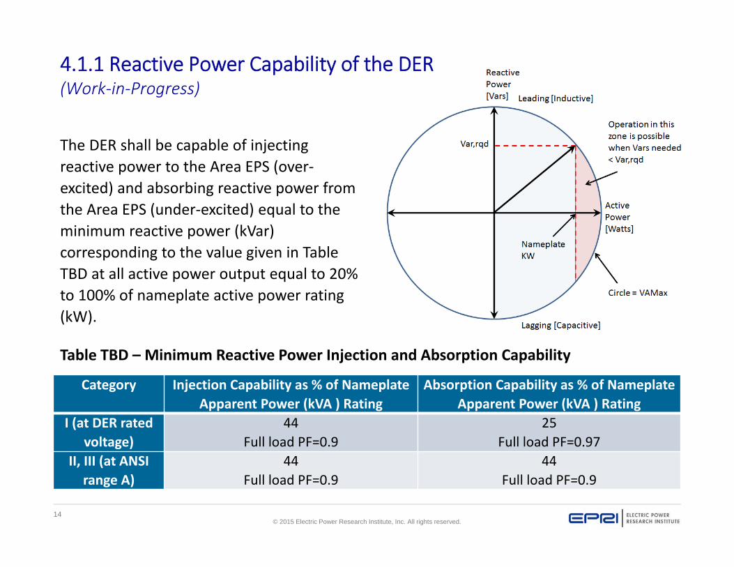
The DER shall be capable of injecting reactive power to the Area EPS (over‐excited) and absorbing reactive power from the Area EPS (under‐excited) equal to the minimum reactive power (kVar) corresponding to the value given in Table TBD at all active power output equal to 20% to 100% of nameplate active power rating (kW).
4.1.1 Reactive Power Capability of the DER(Work‐in‐Progress)
Category Injection Capability as % of Nameplate Apparent Power (kVA ) Rating
Absorption Capability as % of Nameplate Apparent Power (kVA ) Rating
I (at DER rated voltage)
44 Full load PF=0.9
25 Full load PF=0.97
II, III (at ANSI range A)
44Full load PF=0.9
44Full load PF=0.9
Table TBD – Minimum Reactive Power Injection and Absorption Capability
15© 2015 Electric Power Research Institute, Inc. All rights reserved.
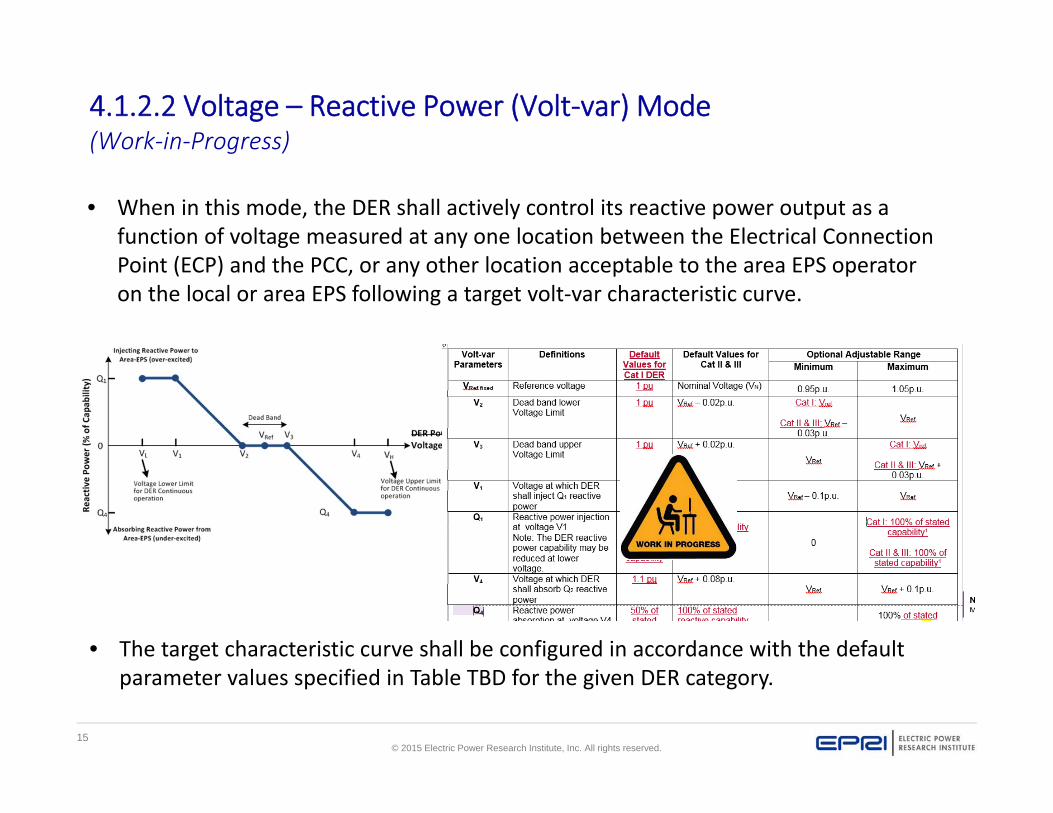
• When in this mode, the DER shall actively control its reactive power output as a function of voltage measured at any one location between the Electrical Connection Point (ECP) and the PCC, or any other location acceptable to the area EPS operator on the local or area EPS following a target volt‐var characteristic curve.
4.1.2.2 Voltage – Reactive Power (Volt‐var) Mode (Work‐in‐Progress)
• The target characteristic curve shall be configured in accordance with the default parameter values specified in Table TBD for the given DER category.

16© 2015 Electric Power Research Institute, Inc. All rights reserved.
IEEE P1547: Foundations for Ride‐Through Requirements
Requirement Category Foundation Justification
Voltage Ride‐Through
Category I German grid code for medium voltage‐connected synchronous generator‐basedDER
• Essential bulk system needs• Attainable by all state‐of‐the‐art
DER technologies
Category II NERC PRC‐024‐2 but w/o stability exception, extended LVRT duration for 65‐88% Vnom
• All bulk system needs• Coordinated with existing
reliability standards• Considering fault‐induced
delayed voltage recovery
Category III CA Rule 21 and Hawaii, minor modifications
• All bulk system needs• Considering fault‐induced
delayed voltage recovery• Distribution system operation
Frequency Ride‐Through
All Categories(harmonized)
CA Rule 21 and Hawaii, exceeds PRC‐024‐2
• All bulk system needs• Low inertia grids
17© 2015 Electric Power Research Institute, Inc. All rights reserved.
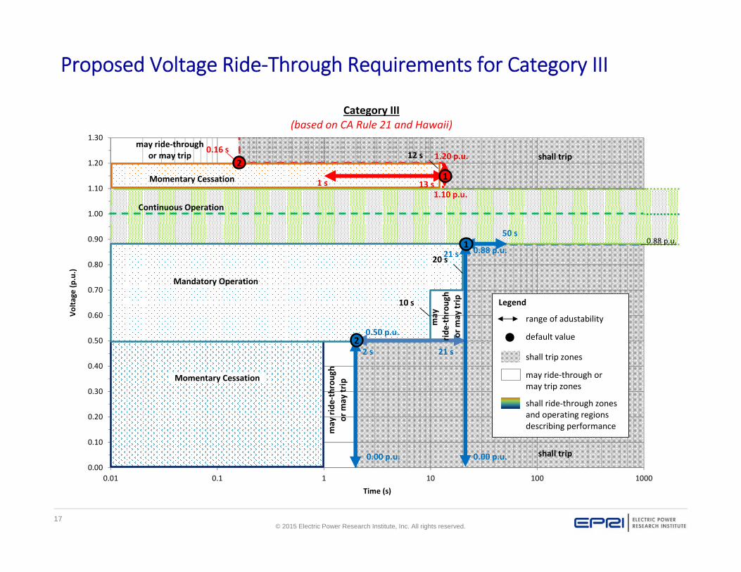
Proposed Voltage Ride‐Through Requirements for Category III
0.00
0.10
0.20
0.30
0.40
0.50
0.60
0.70
0.80
0.90
1.00
1.10
1.20
1.30
0.01 0.1 1 10 100 1000
Volta
ge (p
.u.)
Time (s)
Momentary Cessation
shall trip1.20 p.u.0.16 s
13 s1.10 p.u.
0.00 p.u.
0.88 p.u.
21 s
0.00 p.u.
0.50 p.u.
Continuous Operation
Mandatory Operation
shall trip
10 s
2 s
2
1 s1
2
may ride‐throughor may trip
Momentary Cessation
Category III(based on CA Rule 21 and Hawaii)
20 s21 s
50 s1
may ride
‐throu
ghor m
ay trip
12 s
0.88 p.u.
may
ride‐throug
hor m
ay trip Legend
range of adustability
default value
shall trip zones
may ride‐through ormay trip zones
shall ride‐through zonesand operating regionsdescribing performance
18© 2015 Electric Power Research Institute, Inc. All rights reserved.
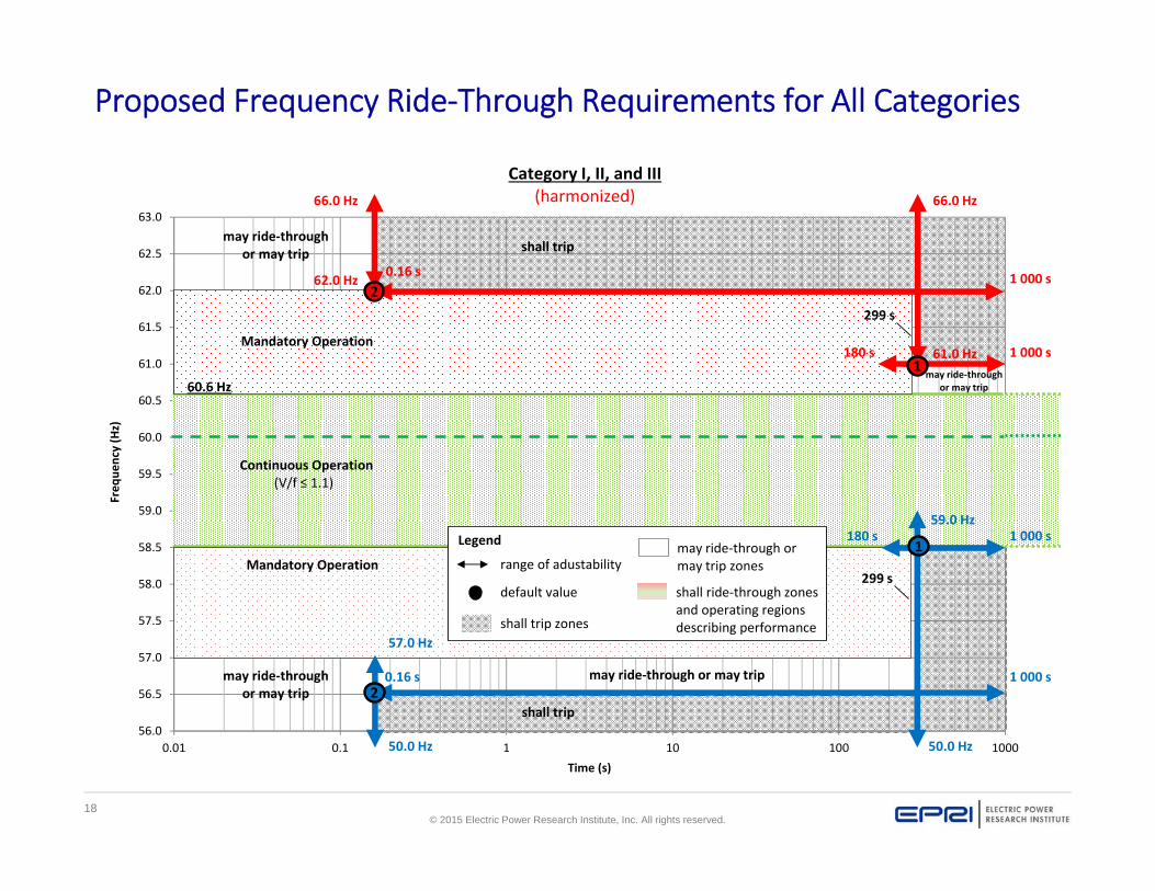
Proposed Frequency Ride‐Through Requirements for All Categories
56.0
56.5
57.0
57.5
58.0
58.5
59.0
59.5
60.0
60.5
61.0
61.5
62.0
62.5
63.0
0.01 0.1 1 10 100 1000
Freq
uency (Hz)
Time (s)
Continuous Operation(V/f ≤ 1.1)
Mandatory Operation
Mandatory Operation
shall trip
shall trip
66.0 Hz 66.0 Hz
1 000 s0.16 s
180 s
62.0 Hz
50.0 Hz
0.16 s 1 000 s
50.0 Hz
57.0 Hz
1 000 s180 s1
2
2
161.0 Hz 1 000 s
59.0 HzLegend
range of adustability
default value
shall trip zones
may ride‐through ormay trip zones
shall ride‐through zonesand operating regionsdescribing performance
may ride‐throughor may trip
may ride‐throughor may trip
may ride‐throughor may trip
Category I, II, and III(harmonized)
299 s
299 s
60.6 Hz
may ride‐through or may trip
19© 2015 Electric Power Research Institute, Inc. All rights reserved.
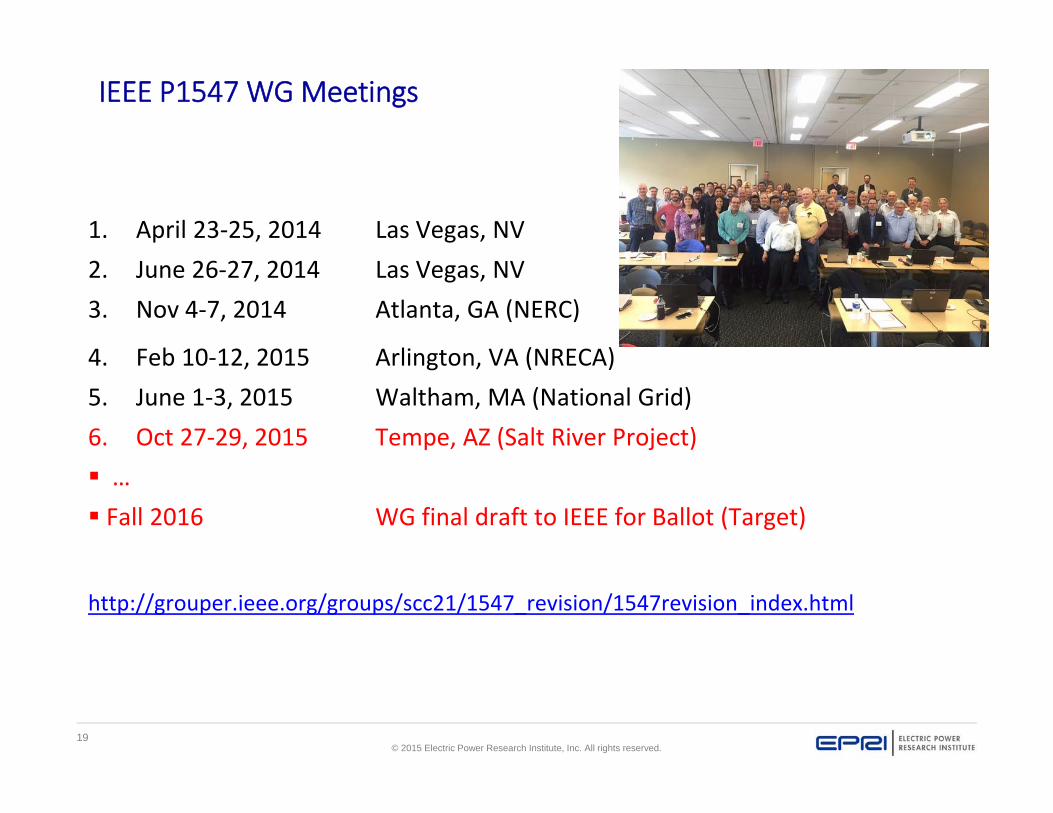
IEEE P1547 WG Meetings
1. April 23‐25, 2014 Las Vegas, NV2. June 26‐27, 2014 Las Vegas, NV3. Nov 4‐7, 2014 Atlanta, GA (NERC)
4. Feb 10‐12, 2015 Arlington, VA (NRECA)5. June 1‐3, 2015 Waltham, MA (National Grid)6. Oct 27‐29, 2015 Tempe, AZ (Salt River Project) … Fall 2016 WG final draft to IEEE for Ballot (Target)
http://grouper.ieee.org/groups/scc21/1547_revision/1547revision_index.html
20© 2015 Electric Power Research Institute, Inc. All rights reserved.
Questions
Contacts:
• Aminul Huque – 865.218.8051, [email protected]

21© 2015 Electric Power Research Institute, Inc. All rights reserved.
Together…Shaping the Future of Electricity