DEPOSITION OF SPUTTERED MOLYBDENUM DISULFIDE …DEPOSITION OF SPUTTERED MOLYBDENUM DISULFIDE FILMS...
16
NASA TECHNICAL NOTE I p,., Z ,,=¢ ,,=: Z NASA TN D-4269 DEPOSITION OF SPUTTERED MOLYBDENUM DISULFIDE FILMS FRICTION CHARACTERISTICS OF SUCH FILMS IN VACUUM AND by Talivaldis Spalvil, s and Joh** S. Przybyszewski Leu,is Research Center ClevelaJ, d, Ohio NATIONAL AERONAUTICS AND SPACE ADMINISTRATION • WASHINGTON, D. C. • DECEMBER 1967 https://ntrs.nasa.gov/search.jsp?R=19680002176 2020-04-24T14:38:46+00:00Z
Transcript of DEPOSITION OF SPUTTERED MOLYBDENUM DISULFIDE …DEPOSITION OF SPUTTERED MOLYBDENUM DISULFIDE FILMS...
NASA TECHNICAL NOTE
I
p,.,
Z
,,=¢
,,=:Z
NASA TN D-4269
DEPOSITION OF SPUTTERED
MOLYBDENUM DISULFIDE FILMS
FRICTION CHARACTERISTICS OF
SUCH FILMS IN VACUUM
AND
by Talivaldis Spalvil, s and Joh** S. Przybyszewski
Leu,is Research Center
ClevelaJ, d, Ohio
NATIONAL AERONAUTICS AND SPACE ADMINISTRATION • WASHINGTON, D. C. • DECEMBER 1967
https://ntrs.nasa.gov/search.jsp?R=19680002176 2020-04-24T14:38:46+00:00Z

NASA TN D-4269
DEPOSITION OF SPUTTERED MOLYBDENUM DISULFIDE FILMS AND
FRICTION CHARACTERISTICS OF SUCH FILMS IN VACUUM
By Talivaldis Spalvins and John S. Przybyszewski
Lewis Research Center
Cleveland, Ohio
NATIONAL AERONAUTICS AND SPACE ADMINISTRATION
For sale by the Clearinghouse for Federal Scientific ond Technical Information
Springfield, Virginia 22151 - CFSTI price $3.00

DEPOSITION OF SPUTTEREDMOLYBDENUM DISULFIDE FILMS AND
FRICTION CHARACTERISTICS OF SUCH FILMS IN VACUUM
by Talivaldis Spalvins and John S. Przybyszewski
Lewis Research Center
SUMMARY
Physical direct-current sputtering of molybdenum disulfide (MoS2) is used to apply
MoS 2 films as a solid lubricant for rotating and sliding components. This method does
not use organic or inorganic binders or the process of burnishing. Friction experiments
in vacuum (10 -11 torr or 1.33><10 -9 N/m 2) were conducted on these films. The coeffi-
cients of friction for the sputtered films were in agreement with the reported values in
the literature. Stoichiometric films were obtained, and no dissociation was observed.
There is a strong bonding (adherence) between the films and the substrate, as indicated
by the long-endurance life of the lubricating films in friction experiments. The sputtered
MoS 2 films had an accurate repeatability in terms of stoichiometry, adherence, thickness,
and uniformity when the sputtering conditions were kept constant.
INTRODUCTION
Molybdenum disulfide (MoS2) is frequently used as a solid lubricant not only in con-
ventional lubrication situations but also in high-temperature and high-vacuum environ-
ments. Solid lubricants are preferred in high-vacuum environments because they gener-
ally have vapor pressures lower than 10 -10 torr (1.33><10 -8 N/m 2) as compared with the
best conventional organic liquid lubricants, which have vapor pressures in the 10 -6 torr
(1.33><10 -4 N/m 2) range. To be durable and effective, lubricant films of MoS 2 must be
firmly bonded to the surface of the materials which require lubrication.
One of the primary problems concerning the use of MoS 2 as a lubricant is the method
of application to the surface to obtain good film adherence. Previously, adherent MoS 2
films had been obtained either by utilizing binders (e. g., thermoplastic or thermosetting
resins or sodium silicate) or by burnishing the substrate material with MoS 2 powder.There are applications where a bonding agent is undesirable or would be a disadvantage,
for example, where the performance of the film may beadversely influenced by certainchemical interactions, particularly those that would affect film adherence, suchas de-
composition of the binder. Burnished MoS2 films leave much to be desired with respectto bonding of the MoS2 to the surface, coefficient of friction, and uniformity of coatingthickness. Further, the friction coefficient of burnished MoS2 films (0.3, ref. 1) ishigher than for most bondedMoS2 films. Electron diffraction examinations of steelsurfaces burnished with MoS2 showedthe surface film to be a complex mixture of ironand molybdenumsulfides (ref. 1). The presenceof this mixture, rather thanpure MoS2,was considered to be responsible for the higher coefficient of friction.
Of the coating methodswhich presently are being intensively investigated for lubrica-tion purposes, the various vacuum-deposition methodsare of particular interest and showstrong adhesion, long-endurance life, and controlled thickness. Although vapor deposi-tion (thermal evaporation) is the simplest and most commonly used deposition technique,
it cannotgenerally be usedfor alloys and compoundssuchas MoS2. The differing vaporpressures of the constituent elements of MoS2 during evaporation render unlikely the con-densation of the vapor as a stoichiometric MoS2 film.
This investigation was conductedto produce thin, uniform, adherent, stoichiometriclubricating films of MoS2 (with a desired thickness) which could be used as lubricantswith long-endurance lives. Molybdenumdisulfide was deposited under controlled experi-mental conditions on two substrates, niobium (Nb)andnickel-chromium (Ni-Cr)alloys, bymeans of physical direct-current sputtering. The friction characteristics and endurance
life of the sputtered MoS2 films on Ni-Cr and Nb substrates were examined in ultra-highvacuum (10-11 torr or 1.33><10-9 N/m2). The friction experiments were conductedwith
a hemispherical rider of Nb sliding on the thin film of MoS2 which was depositedon thedisk surface.
AP PARATU S
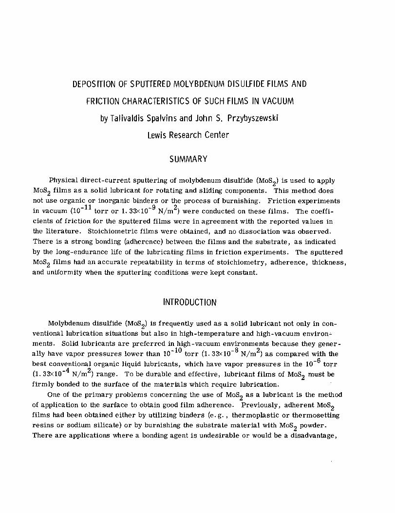
TriodeDirect-CurrentSputteringApparatus
A sputtering system was constructed utilizing a three electrode (triode) geometry
consisting of a thermionic cathode, an anode, and the target. This system is shown
schematically in figure l(a) and photographically in figure lib). The components of the
sputtering system are enclosed in the vacuum chamber (45-cm bell jar). The compo-
nents are as follows:
(1) Thermionic cathode, a spiraled filament of 0.1-centimeter-thick tungsten wire
which, when heated, acts as a thermionic electron source
- High-voltage 1
power [--
supp y J
Bell jar-_
Quartz
cylinder-._
Specimen-.. ""\
\
Switch positions
1 Substrate cleaning
2 Target sputtering
I
cathode(filament)
To vacuum
pumps
CD-g208
(a) Schematic diagram.
Quadz
High-voltage cylinderfeedth rough .....
Thermionic cathode
(filament and shield) .....
",.,
(b) Actual apparatus.
Figure i. - Triode direct-current sputtering apparatus,
Bell jar//
..,_ Thermocouple/ feedth rough
,.,..,--Specimen
..,,- Target
,...-" (MoS 2),/
- Water-coolod
target holder
inlet
variable leak
controller
i
(2) Anode, a flat stainless-steel disk to which a positive potential of about 500 volts
was applied to establish a glow discharge between it and the thermionic cathode
(3) Target, the material to be deposited, a cylindrically shaped compact of MoS 2
(1.3 cm in diam and about 5 cm in length).
This MoS 2 cylindrical compact was made without a binder by utilizing compacting
pressures of 50 000 to 100 000 psi (34.47x10⁷ to 68.94x10⁷ N/m2). The MoS 2
target was held in a water-cooled holder, in order to keep the target tempera-
ture from rising excessively. A negative potential was applied to this target.
(4) The substrate material (Nb and a Ni-Cr alloy disk) placed close to target mate-
rlal on which the atoms ejected from the target were deposited to form a con-
tinuous film
A thermocouple gage monitored the chamber pressure during sputtering, and pure
argon was admitted to the vacuum chamber through a variable leak-control valve.
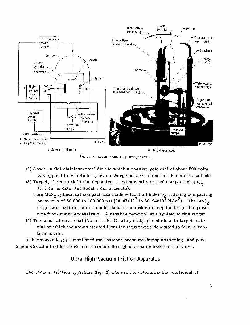
Ultra-High-Vacuum Friction Apparatus
The vacuum-friction apparatus (fig. 2) was used to determine the coefficient of
3

Water-cooled
support bearing-_
1o ion pumpand mechanical
pumping system-,
Hydraulicdrive motor
4-Magnetic-d rive assembly
FDisk specimen
Water-cooled
su
Molecular //
flowsealJPower
SU
Mass gun with
tungstenassembly filament
-To ion
pump andmechanical
pumping
system
Glass window
speci men
-Bellows Frictionalforce
\
Gimbal Load
assembly
Cold-cathode
vacuum gage
CD-7939
Mass
spectrometer-q
Specimen
./
Electron
/-Liquid/ helium
/
t- Bearing chamberI
"-- Magnetic-drive
assembly
Strain-measuring
assembly
L Speci men _
Figure 2. - Ultra-high-vacuum friction apparatus,
CD-7938
friction for the coated and uncoated surfaces. The apparatus has two distinct chambers,
the specimen chamber and the bearing chamber, both of which are connected to the fore-
pumping system.
The forepumping system of the apparatus includes a cold trap made up of molecular
sieves backed by liquid-nitrogen-cooled containers. This system is connected to two
mechanical pumps through a 5-centimeter stainless-steel vacuum valve.
The specimen chamber is connected to the mechanical pumping system by a bakable
high-vacuum valve and is provided with a 400-liter-per-second ion pump, as well as
cryopumping surfaces (liquid nitrogen and liquid helium). The specimen chamber con-
tains a cold-cathode discharge vacuum gage for measuring pressures. The pressure in
the specimen chamber was approximately 10 -11 torr (1.33x10 -9 N/m2). The specimen
and bearing chambers were baked at 644 ° and 477 ° K, respectively.
The bearing chamber, which is connected to the forepumping system by a 5-
centimeter valve, is equipped with a 125-liter-per-second ion pump. The bearing
chamber also contains a liquid-nitrogen-cooled titanium sublimation pump. Pressure
in the bearing chamber was about 10 -10 torr (1.33x10 -8 N/m2).
The shaft projects through the rear wall of the test chamber by means of a molecular
flow seal (fig. 2). On the bearing-chamber end of the shaft a 20-pole magnet is mounted
and is separated from the drive magnet, which is outside the vacuum chamber, by a
0.08-centimeter diaphragm (0.40-cm air gap). The drive magnet is powered by a hy-
draulic motor with a variable speed capability. Because of instabilities in the drive
motor at low speeds (10, 20, and 100 rpm), these speeds were obtained by utilizing a
speed reducer with a ratio of 10.
The shaft is supported on bearings in the bearing chamber. The shaft-support bear-
ings have a large clearance and are mounted in a cartridge so that the shaft expansion
takes place into the test chamber. Thus, the possibility of the magnet striking the
diaphragm is eliminated. Because loading was applied by deadweights, the expansion
did not change the load on the specimens. The bearing cartridge was water cooled to
prevent any damage to the bearings during the bake-out cycle.
The 6.35-centimeter-diameter disk specimen was mounted on the end of the
horizontal shaft in the test chamber. Against the disk, a 0.47-centimeter-radius
hemispherical rider specimen was loaded. The rider was held in place by a rigid arm,
which projects through a port in the side of the vacuum chamber. The seal was made at
the wall by utilizing a bellows connection between the chamber wall and the rigid arm. A
removable gimbal assembly, which is used to load the rider against the disk surface and
to monitor the frictional force through a strain-gage assembly, was fastened to the rigid
arm outside the vacuum chamber. A sliding velocity of 2.54×10 -2 meter per second
was used for these experiments.
SPUTTERING MECHANISM AND PROCEDURE
Sputtering is generally performed in an argon atmosphere of several microns pres-
sure. A potential is applied across the electrodes to ionize the gas. The material to be
sputtered is made the cathode (target). The material sputtered from the target is ejected
through the plasma and deposited as a film on the specimen. The basic mechanism of
sputtering is thus a process where the positive argon ions, which form a gaseous plasma,
are accelerated through an electron-free region (Langmuir sheath) with sufficient energy
(40 to 60 eV or 6.4x10- 18 j) to knock off or sputter the negatively charged target mate-
rial. In explaining the actual sputtering phenomena, current theories (refs. 2 to 4) favor
a momentum exchange energy transfer. The sputtered material is deposited on the
specimen, which is placed close to the target source. For compounds, such as MoS2,
which have a wide disparity in vapor pressure of the constituents, the material can be
deposited nearly stoichiometrically without thermal dissociation. In this method, the
basic mechanism is essentially independent of the target temperature, provided the
target temperature is below the vaporization or dissociation temperature of the target
material.
In this experiment, the bell jar was evacuated to a pressure of approximately 10 -7
torr (1.33x10⁻⁵ N/m 2) and subsequently purged several times with pure argon through a
variable leak valve. Finally, the system was again evacuated, and argon was introduced
at a controlled rate. A constant pressure was maintained in the bell jar at about 10-3torr
(1.33x10 -1 N/m2). A positive potential (fig. l(a)) of about 500 volts (relative to the fila-
ment) was applied to the anode. The thermionic cathode emitter (tungsten filament) was
heated to emission temperature, and a glow discharge occurred. A negative potential
(fig. l(a)) of 2000 to 4000 volts was then applied to the specimen. This application re-
sulted in the attraction of positive argon ions from the gas discharge. The impingement
of the argon ions on the surface of the specimen resulted in a cleaning action by sputter-
ing. After the cleaning process had continued for about 20 minutes, the negative poten-
tial on the specimen was quickly switched to the target material (MoS2). This procedure
resulted in bombardment of the target by the argon ions, which were attracted by its
negative potential. Molybdenum disulfide was therefore sputtered from the surface of the
target and subsequently deposited on the previously cleaned specimen. The spacing be-
tween the target and the specimen was about 4 centimeters.
6
RESULTSAND DISCUSSION
Molybdenum Disulfide Film Deposition by Sputtering
Molybdenum disulfide was sputtered on Nb and Ni-Cr alloy surfaces. These speci-
mens were selectedbecausethey were used in previous studies (ref. 5). The original
MoS2 cylindrical target material and the sputtered MoS2 films were analyzed chemicallyand spectrographically. The weight percentages of the constituent elements are listedin table I. The increased weight percentage of iron in the sputtered film probably camefrom the stainless-steel filament holders, which were also sputtered to some extent.
TABLE I. - CHEMICAL AND SPECTROGRAPHIC
ANALYSIS OF MOLYBDENUM DISULFIDE
Element
Mo
S
Fe
Original MoS 2 powder Sputtered film
(target material)
Concentration, wt. %
58.60 48.75
39.44 38.90
• 12 9.75
The sputtered MoS 2 film was scraped off a reference glass slide and was analyzed
by X-ray diffraction (Debye-Scherrer powder method). The diffraction maximums ob-
tained in this method had broad lines, and, therefore, it was not possible to make accur-
ate readings. Line broadening is generally caused by particle sizes in the range 2×10⁻⁵
to 10 -6 centimeter or by strain effects (ref. 6). When the particles are much smaller
than 100 angstroms (10 -8 m) the diffraction lines are so broad that it is not possible to
distinguish them from the general background. Consequently, it was not possible to
make any measurements. In this investigation, the line broadening was probably caused
by the small size of the sputtered particles. It was concluded that the MoS 2 film, which
was deposited, consisted of very small particles, since sharp X-ray diffraction lines
could not be obtained. Tnese X-ray diffraction results for sputtered MoS 2 are in agree-
ment with the general concept that sputtered films normally are not crystalline, unless
the specimen is heated to recrystallization temperature. In this investigation, the speci-
men temperature was approximately 477 ° K. In sputtering a continuous film forms im-
mediately, without nucleation. In all vapor-deposition methods, however, the film is
formed in two steps: nucleation (at selected surface sites) followed by growth.
The thicknesses of the sputtered films were measured with an interference micro-
scope on a reference glass slide located at the same distance from the target as the
specimen. The films were in the range of 2000 to 3000 angstroms thick.
The significant feature of this method of applying MoS 2 to a substrate material is the
avoidance of nonstoichiometry arising from dissociation. These studies indicate that
nearly stoichiometric films can be obtained by sputtering MoS 2.
7
Friction and Endurance Characteristics of Sputtered Molybdenum Disulfide
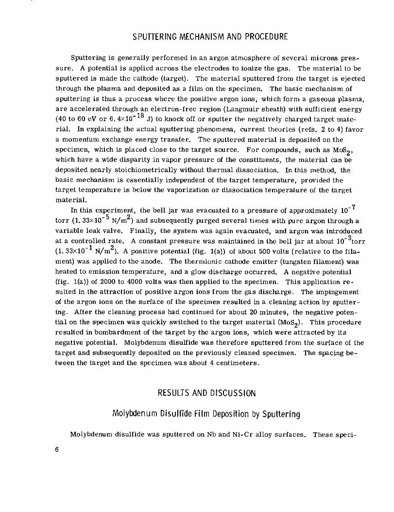
The friction characteristics and endurance life of the sputtered MoS 2 films on Nb andNi-Cr alloy substrates were examined in ultra-high vacuum (10 -11 torr or 1.33×10 -9
N/m2). Actual traces of a friction experiment are shown in figure 3. The trace in fig-
ure 3(a) is typical for Nb sliding on Nb (without lubricant). The amplitude of the friction
curve is relatively large, and the average coefficient of friction is 1.12. The friction
L8
.8 00 2.5 0 2.5 5.0 7.5 10.0 12.5 15.0
Time, min
(a) No lubricant. (b) Sputtered molybdenumdisulfidefilm lubricant 2000angstroms(2xl0"7 m) thick.
Figure3. - Actual friction tracesof niobiumsliding on coatedand uncoatedniobium. Pressure, 10"11 torr (1.33x10⁻⁹ N/m2); load,250grams; speed,.5feet per minute (2.54x10"2 m/sec).
trace in figure 3(b) is for Nb sliding on a Nb surface coated with sputtered MoS 2 film.
The coefficient of friction is about 0.09, and the friction curve is smooth with practically
no amplitude.
The actual friction traces in figure 3 were used to determine the average coefficients
of friction in order to determine the friction curves in figure 4(a). The friction curve
for sputtered MoS 2 on an Nb substrate with a film thickness of about 2000 angstroms
(fig. 4(a)) maintained a constant coefficient of friction of 0.09 for more than 5 hours.
c
o=
ta_
1.
.2
,,E3-4 3---_ 9----4 _
Lubricant
[] None
/', Sputtered MoS2 film
No failure
J ,_ ,kZ
1.3
[
2
(a) Specimen, niobium.
r....-- r
0 40 80 120 160 200 240 280 320
Time, rain
(b) Specimen, nickel-chrome alloy.
Figure 4. - Average friction coefficients of niobium sliding on two different specimens coated
with sputtered molybdenum disulfide in vacuum (10-11 torr or 1. 33x10-9 NIm2}. Load,
250 grams; speed, 5 feet per minute (2. 54x10-2 m/sec); ambient temperature.
The sputtered MoS 2 lubricant film had not failed after 5 hours. The nominal range for
the coefficient of friction for MoS 2 films is considered to be 0.03 to 0.08, as derived
from many sources. The coefficient of friction for sputtered MoS 2 films is in agreement
with the reported values.
The friction curve for the sputtered MoS 2 on the Ni-Cr alloy substrate (fig. 4(b))
maintains a constant coefficient of friction (0. 06) for more than 3 hours. Beyond this
time, the coefficient of friction gradually increases. As the film (about 2000 .£. thick)
was broken, the coefficient of friction did not rise abruptly. As wear took place, the
coefficient of friction rose gradually until it approached the coefficient of friction of the
substrate material (1.22). These two friction curves (fig. 4) clearly indicate that sput-
tered MoS 2 films maintain the characteristic low coefficient of friction of MoS 2 and give
relatively long-endurance lives during the friction experiment.
The durability of this thin (2000 to 3000 ._) MoS 2 film indicates that there was strong
bonding adherence between the sputtered film and the substrate material, which subse-
quently minimized breakage or chipping during the friction test. These friction tests
give good qualitative measure of film adherence. Generally, the film adherence to the
substrate depends on such parameters as energy of ion bombardment, substrate cleanli-
ness, substrate temperature, compatibility of preferred crystal lattices, and relative
atomic bonding energies. The thicknesses measured by interference microscope showed
a good uniformity of thickness over the 6.35-centimeter-diameter disk. When the
sputtering conditions during the deposition are kept constant, an exceptional repeatability
of film thickness can be maintained.
These superior adherence characteristics of the sputtered MoS 2 film are caused by
several factors: (1) cleaning of the substrate by sputtering prior to deposition, (2) the
relatively high energies of the sputtered material, and (3) the continuous cleaning of the
surface by the glow discharge itself. The cleaning of a surface by ion bombardment re-
sults in an etching of that surface (ref. 7). The surface is free of the skin effects of cold
working that may be produced during mechanical polishing.
SUMMARY OF RESULTS
This investigation introduces a vacuum-deposition method (sputtering) for applying
molybdenum disulfide (MoS2) films to substrate materials. The method uses neither
organic or inorganic binders nor the process of burnishing. The friction experiments
showed that the coefficients of friction of the sputtered MoS 2 film (0.06 to 0.09) are in
agreement with the values (0.03 to 0. 08) reported in the literature for resin-bonded films.
This agreement in friction coefficients results from the preserved stoichiometry of the
sputtered film. The durability of the lubricating film gives a qualitative test of the strong
bonding adherence between film and substrate. The film thickness was uniform, and re-
peatability of film thickness was maintained.
Lewis Research Center,
National Aeronautics and Space Administration,
Cleveland, Ohio, August 24, 1967,
129-03-13-02-22.
REFERENCES
1. Johnson, Robert L. ; Buckley, Donald H. ; and Swikert, Max A. : Studies of Lubri-
cating Materials in Vacuum. Paper presented at the USAF-Southwest Research Inst.
Aerospace Bearing Conference, San Antonio, Texas, Mar. 25-27, 1964.
2. Wehner, G. K. : Sputtering by Ion Bombardment. Advances in Electronics and Elec-
tron Physics. Vol. 7. L. Marton, ed., Academic Press, 1955, pp. 239-298.
10
3. Kay, Eric: Impact Evaporation and Thin Film Growth in a Glow Discharge. Advancesin Electronics and Electron Physics. Vol. 17. L. Matron, ed., Academic Press,1962, pp. 245-322.
4. Anon. : Ionic BombardmentTheory andApplications; International Symposiumof theNational Scientific ResearchCenter, Dec. 4-8, 1962. Gordonand Breach SciencePublishers, 1964.
5. Spalvins, T. ; and Buckley, D. H. : Vapor Deposited Gold Thin Films as Lubricants
in Vacuum (10 -11 mm Hg). J. Vacuum Sci. Tech., vol. 3, no. 3, May-June 1966,
pp. 107-113.
6. Az{troff, Leonid V. ; and Buerger, Martin J. : The Powder Method in X-Ray
Crystallography. McGraw-Hill Book Co., Inc., 1958, pp. 246-266.
7. Bierlein, T. K. ; Newkirk, H. W., Jr., and Mastel, B. : Etching of Refractories
and Cermets by Ion Bombardment. J. Am. Ceramic Soc., vol. 41, no. 6, June
1958, pp. 196-200.
NASA-Lal/gley, 1967 -- 17 E-4044 II


![THE FACTS ABOUT MOLY ppt [Kompatibilitätsmodus]schaefferoil.de/sheets/praesentationen/factmoly_en.pdf · MOLYBDENUM DISULFIDE (Mos 2) The first recorded use of Molybdenum Disulfide](https://static.fdocuments.in/doc/165x107/5a70544d7f8b9a93538be93b/the-facts-about-moly-ppt-kompatibilittsmodusschaefferoildesheetspraesentationenfactmolyenpdfpdf.jpg)