Deploying HPC Cluster with Mellanox InfiniBand Interconnect Solutions · 2017-01-27 · Deploying...
40
www.mellanox.com Mellanox ® Technologies Deploying HPC Cluster with Mellanox InfiniBand Interconnect Solutions Reference Design Rev 1.3 January 2017
Transcript of Deploying HPC Cluster with Mellanox InfiniBand Interconnect Solutions · 2017-01-27 · Deploying...

www.mellanox.com
Mellanox® Technologies
Deploying HPC Cluster with Mellanox InfiniBand Interconnect Solutions
Reference Design
Rev 1.3
January 2017

2 Document Number: MLNX-15-623
Mellanox® Technologies
NOTE:
THIS HARDWARE, SOFTWARE OR TEST SUITE PRODUCT (“PRODUCT(S)”) AND ITS RELATED DOCUMENTATION ARE PROVIDED BY MELLANOX TECHNOLOGIES “AS-IS” WITH ALL FAULTS OF ANY KIND AND SOLELY FOR THE PURPOSE OF AIDING THE CUSTOMER IN TESTING APPLICATIONS THAT USE THE PRODUCTS IN DESIGNATED SOLUTIONS. THE CUSTOMER'S MANUFACTURING TEST ENVIRONMENT HAS NOT MET THE STANDARDS SET BY MELLANOX TECHNOLOGIES TO FULLY QUALIFY THE PRODUCT(S) AND/OR THE SYSTEM USING IT. THEREFORE, MELLANOX TECHNOLOGIES CANNOT AND DOES NOT GUARANTEE OR WARRANT THAT THE PRODUCTS WILL OPERATE WITH THE HIGHEST QUALITY. ANY EXPRESS OR IMPLIED WARRANTIES, INCLUDING, BUT NOT LIMITED TO, THE IMPLIED WARRANTIES OF MERCHANTABILITY, FITNESS FOR A PARTICULAR PURPOSE AND NON INFRINGEMENT ARE DISCLAIMED. IN NO EVENT SHALL MELLANOX BE LIABLE TO CUSTOMER OR ANY THIRD PARTIES FOR ANY DIRECT, INDIRECT, SPECIAL, EXEMPLARY, OR CONSEQUENTIAL DAMAGES OF ANY KIND (INCLUDING, BUT NOT LIMITED TO, PAYMENT FOR PROCUREMENT OF SUBSTITUTE GOODS OR SERVICES; LOSS OF USE, DATA, OR PROFITS; OR BUSINESS INTERRUPTION) HOWEVER CAUSED AND ON ANY THEORY OF LIABILITY, WHETHER IN CONTRACT, STRICT LIABILITY, OR TORT (INCLUDING NEGLIGENCE OR OTHERWISE) ARISING IN ANY WAY FROM THE USE OF THE PRODUCT(S) AND RELATED DOCUMENTATION EVEN IF ADVISED OF THE POSSIBILITY OF SUCH DAMAGE.
Mellanox Technologies 350 Oakmead Parkway Suite 100 Sunnyvale, CA 94085 U.S.A. www.mellanox.com Tel: (408) 970-3400 Fax: (408) 970-3403
Mellanox Technologies, Ltd. Beit Mellanox PO Box 586 Yokneam 20692 Israel www.mellanox.com Tel: +972 (0)74 723 7200
Fax: +972 (0)4 959 3245
© Copyright 2017. Mellanox Technologies. All Rights Reserved. Mellanox®, Mellanox logo, BridgeX®, ConnectX®, CORE-Direct®, InfiniBridge®, InfiniHost®, InfiniScale®, MLNX-OS®, PhyX®, SwitchX®, UFM®, Virtual Protocol Interconnect® and Voltaire® are registered trademarks of Mellanox Technologies, Ltd.
Connect-IB™, FabricIT™, Mellanox Open Ethernet™, Mellanox Virtual Modular Switch™, MetroX™, MetroDX™, ScalableHPC™, Unbreakable-Link™ are trademarks of Mellanox Technologies, Ltd. All other trademarks are property of their respective owners.

Error! No text of specified style in document. Rev 1.3
3
Mellanox® Technologies
Contents 1 Introduction ..................................................................................................................................... 9
2 Designing an HPC Cluster ........................................................................................................... 10
2.1 Fat-Tree Topology ................................................................................................................ 10
2.1.1 Rules for Designing the Fat-Tree Cluster ............................................................... 11
2.1.2 Blocking Scenarios for Small Scale Clusters .......................................................... 12
2.1.3 Topology Examples ................................................................................................ 14
2.2 Performance Calculations .................................................................................................... 17
2.3 Communication Library Support ........................................................................................... 18
2.3.1 Fabric Collective Accelerator .................................................................................. 18
2.3.2 Mellanox Messaging ............................................................................................... 19
2.4 Quality of Service.................................................................................................................. 20
2.5 Locating the Subnet Manager .............................................................................................. 20
2.6 Unified Fabric Management ................................................................................................. 21
2.6.1 Dashboard .............................................................................................................. 21
2.6.2 Advanced Monitoring Engine .................................................................................. 21
2.6.3 Traffic and Congestion Map .................................................................................... 22
2.6.4 Health Report .......................................................................................................... 22
2.6.5 Event Management ................................................................................................. 22
2.6.6 Central Device Management .................................................................................. 22
2.6.7 Fabric Abstraction ................................................................................................... 22
3 Installation ..................................................................................................................................... 23
3.1 Hardware Requirements ....................................................................................................... 23
3.2 Software Requirements ........................................................................................................ 23
3.3 Hardware Installation ............................................................................................................ 23
3.4 Driver Installation .................................................................................................................. 23
3.5 HPC-X Installation ................................................................................................................ 25
3.6 Loading the HPC-X Environment from bash ........................................................................ 25
3.7 Loading the HPC-X Environment from Modules .................................................................. 26
4 Configuration ................................................................................................................................. 27
4.1 Subnet Manager Configuration ............................................................................................. 27
4.1.1 Configuring the SM on a Server ............................................................................. 27
4.1.2 Configuring the SM on a Switch ............................................................................. 27
5 Verification & Testing ................................................................................................................... 29

Rev 1.3 Error! No text of specified style in document.
4
Mellanox® Technologies
5.1 Verifying End-Node is Up and Running ................................................................................ 29
5.1.1 Debug Recommendation ........................................................................................ 29
5.2 Verifying Cluster Connectivity ............................................................................................... 30
5.3 Verifying Cluster Topology ................................................................................................... 30
5.4 Verifying Physical Interconnect is Running at Acceptable BER ........................................... 31
5.4.1 Debug Recommendation ........................................................................................ 33
5.5 Running Basic Performance Tests ....................................................................................... 33
5.6 Stress Cluster ....................................................................................................................... 34
Appendix A: Best Practices ....................................................................................................... 36
A.1 Cabling .................................................................................................................................. 36
A.1.1 General Rules ......................................................................................................... 36
A.1.2 Zero Tolerance for Dirt ............................................................................................ 37
A.1.3 Installation Precautions ........................................................................................... 37
A.1.4 Daily Practices ........................................................................................................ 37
A.2 Labeling ................................................................................................................................ 38
A.2.1 Cable Labeling ........................................................................................................ 38
A.2.2 Node Labeling ......................................................................................................... 39
Appendix B: Ordering Information ............................................................................................ 40

Error! No text of specified style in document. Rev 1.3
5
Mellanox® Technologies
List of Figures Figure 1: Basic Fat-Tree Topology ........................................................................................................ 10 Figure 2: 324-Node Fat-Tree Using 36-Port Switches .......................................................................... 11 Figure 3: Balanced Configuration .......................................................................................................... 12 Figure 4: 1:2 Blocking Ratio .................................................................................................................. 12 Figure 5: Three Nodes Ring Topology .................................................................................................. 13 Figure 6: Four Nodes Ring Topology – Creating Credit-Loops ............................................................. 13 Figure 7: 72-Node Fat-Tree Using 1U Switches ................................................................................... 14 Figure 8: 324-Node Fat-Tree Using Director or 1U Switches ............................................................... 14 Figure 9: 648-Node Fat-Tree Using Director or 1U Switches ............................................................... 15 Figure 10: 1296-Node Fat-Tree Using Director and 1U Switches ......................................................... 15 Figure 11: 1944-Node Fat-Tree Using Director and 1U Switches ......................................................... 16 Figure 12: 3888-Node Fat-Tree Using Director and 1U Switches ......................................................... 16 Figure 13: Communication Libraries ..................................................................................................... 18 Figure 14: Cabling ................................................................................................................................. 38

Rev 1.3 Error! No text of specified style in document.
6
Mellanox® Technologies
List of Tables Table 1: Revision History ......................................................................................................................... 7 Table 2: Related Documentation ............................................................................................................. 8 Table 3: HPC Cluster Performance ....................................................................................................... 17 Table 4: Required Hardware ................................................................................................................. 23 Table 5: Recommended Cable Labeling ............................................................................................... 39 Table 6: Ordering Information................................................................................................................ 40

Deploying HPC Cluster with Mellanox InfiniBand Interconnect Solutions Rev 1.3
7
Mellanox® Technologies
Revision History Table 1: Revision History
Revision Date Description
1.3 January, 2017 Added HPC-X
1.2 29 June, 2016 Fixed typo in Section 2.1 “Fat-Tree Topology” on page 10
1.1 June 2014 Minor updates
1.0 September, 2013 First release

Rev 1.3 Introduction
8
Mellanox® Technologies
Preface
About this Document
This reference design describes how to design, build, and test a high performance compute (HPC) cluster using Mellanox® InfiniBand interconnect.
Audience
This document is intended for HPC network architects and system administrators who want to leverage their knowledge about HPC network design using Mellanox® InfiniBand interconnect solutions.
The reader should have basic experience with Linux programming and networking.
References
For additional information, see the following documents:
Table 2: Related Documentation
Reference Location
Mellanox OFED for Linux User Manual
www.mellanox.com > Products > Adapter IB/VPI SW > Linux SW/Drivers
http://www.mellanox.com/content/pages.php?pg=products_dyn&product_family=26&menu_section=34
Mellanox HPC-X Toolkit www.mellanox.com > Products > Software > HPC-X
http://www.mellanox.com/page/products_dyn?product_family=189&mtag=hpc-x
Mellanox Firmware Tools www.mellanox.com > Products > Software > Management Software
http://www.mellanox.com/pdf/MFT/MFT_user_manual.pdf
UFM User Manual www.mellanox.com > Products > Software > Firmware Tools
http://www.mellanox.com/page/products_dyn?product_family=100&mtag=unified_fabric_manager
Mellanox Products Approved Cable Lists
http://www.mellanox.com/related-docs/user_manuals/Mellanox_approved_cables.pdf
Top500 website www.top500.org

Deploying HPC Cluster with Mellanox InfiniBand Interconnect Solutions Rev 1.3
9
Mellanox® Technologies
1 Introduction High-performance computing (HPC) encompasses advanced computation over parallel processing, enabling faster execution of highly compute intensive tasks such as climate research, molecular modeling, physical simulations, cryptanalysis, geophysical modeling, automotive and aerospace design, financial modeling, data mining and more. High-performance simulations require the most efficient compute platforms. The execution time of a given simulation depends upon many factors, such as the number of CPU/GPU cores and their utilization factor and the interconnect performance, efficiency, and scalability. Efficient high-performance computing systems require high-bandwidth, low-latency connections between thousands of multi-processor nodes, as well as high-speed storage systems.
This reference design describes how to design, build, and test a high performance compute (HPC) cluster using Mellanox® InfiniBand interconnect covering the installation and setup of the infrastructure including:
• HPC cluster design
• Installation and configuration of the Mellanox Interconnect components
• Cluster configuration and performance testing

Rev 1.3 Designing an HPC Cluster
10
Mellanox® Technologies
2 Designing an HPC Cluster There are several common topologies for an InfiniBand fabric. The following lists some of those topologies:
• Fat tree: A multi-root tree. This is the most popular topology.
• 2D mesh: Each node is connected to four other nodes; positive, negative, X axis and Y axis
• 3D mesh: Each node is connected to six other nodes; positive and negative X, Y and Z axis
• 2D/3D torus: The X, Y and Z ends of the 2D/3D mashes are “wrapped around” and connected to the first node
• Additional topologies supported by InfiniBand include Dragonfly+, 6D-torus, and Hypercube
Figure 1: Basic Fat-Tree Topology
2.1 Fat-Tree Topology A fat-tree topology is the most widely used topology in HPC clusters. This topology typically enables the best performance at a large scale when configured as a non-blocking network. Where over-subscription of the network is tolerable, it is possible to configure the cluster in a blocking configuration as well. A fat-tree cluster typically uses the same bandwidth for all links and in most cases it uses the same number of ports in all of the switches.

Deploying HPC Cluster with Mellanox InfiniBand Interconnect Solutions Rev 1.3
11
Mellanox® Technologies
Figure 2: 324-Node Fat-Tree Using 36-Port Switches
2.1.1 Rules for Designing the Fat-Tree Cluster The following rules must be adhered to when building a fat-tree cluster:
• Non-blocking clusters must be balanced. The same number of links must connect a Level-2 (L2) switch to every Level-1 (L1) switch. Whether over-subscription is possible depends on the HPC application and the network requirements.
• If the L2 switch is a director switch (that is, a switch with leaf and spine cards), all L1 switch links to an L2 switch must be evenly distributed among leaf cards. For example, if six links run between an L1 and L2 switch, it can be distributed to leaf cards as 1:1:1:1:1:1, 2:2:2, 3:3, or 6. It should never be mixed, for example, 4:2, 5:1.
• Do not create routes that must traverse up, back-down, and then up the tree again. This creates a situation called credit loops and can manifest itself as traffic deadlocks in the cluster. In general, there is no way to avoid credit loops. Any fat-tree with multiple directors plus edge switches has physical loops which are avoided by using a routing algorithm such as up-down.
• Try to always use 36-port switches as L1 and director class switches in L2. If this cannot be maintained, please consult a Mellanox® technical representative to ensure that the cluster being designed does not contain credit loops.
For assistance in designing fat-tree clusters, the Mellanox InfiniBand Configurator (http://www.mellanox.com/clusterconfig) is an online cluster configuration tool that offers flexible cluster sizes and options.

Rev 1.3 Designing an HPC Cluster
12
Mellanox® Technologies
Figure 3: Balanced Configuration
2.1.2 Blocking Scenarios for Small Scale Clusters In some cases, the size of the cluster may demand end-port requirements that marginally exceed the maximum possible non-blocking ports in a “tiered” fat-tree.
For example, if a cluster requires only 36 ports, it can be realized with a single 36-port switch building block. As soon as the requirement exceeds 36 ports, one must create a 2-level (tier) fat-tree. For example, if the requirement is for 72 ports, to achieve a full non-blocking topology, one requires six 36-port switches. In such configurations, the network cost does not scale linearly to the number of ports, rising significantly. The same problem arises when one crosses the 648-port boundary for a 2-level full non-blocking network. Designing a large cluster requires careful network planning. However, for small or mid-sized systems, one can consider a blocking network or even simple meshes.
Consider the case of 48-ports as an example. This cluster can be realized with two 36-port switches with a blocking ratio of 1:2. This means that there are certain source-destination communication pairs that cause one switch-switch link to carry traffic from two communicating node pairs. On the other hand, this cluster can now be realized with two switches instead of more.
Figure 4: 1:2 Blocking Ratio
The same concept can be extended to a cluster larger than 48 ports.
Note that a “ring” network beyond three switches is not a valid configuration and creates credit-loops resulting in network deadlock.

Deploying HPC Cluster with Mellanox InfiniBand Interconnect Solutions Rev 1.3
13
Mellanox® Technologies
Figure 5: Three Nodes Ring Topology
Figure 6: Four Nodes Ring Topology – Creating Credit-Loops

Rev 1.3 Designing an HPC Cluster
14
Mellanox® Technologies
2.1.3 Topology Examples
2.1.3.1 CLOS-3 Topology (Non-Blocking) Figure 7: 72-Node Fat-Tree Using 1U Switches
Figure 8: 324-Node Fat-Tree Using Director or 1U Switches

Deploying HPC Cluster with Mellanox InfiniBand Interconnect Solutions Rev 1.3
15
Mellanox® Technologies
Figure 9: 648-Node Fat-Tree Using Director or 1U Switches
Note that director switches are basically a fat-tree in a box.
2.1.3.2 CLOS-5 Topology (Non-Blocking) Figure 10: 1296-Node Fat-Tree Using Director and 1U Switches

Rev 1.3 Designing an HPC Cluster
16
Mellanox® Technologies
Figure 11: 1944-Node Fat-Tree Using Director and 1U Switches
Figure 12: 3888-Node Fat-Tree Using Director and 1U Switches
Deploying HPC Cluster with Mellanox InfiniBand Interconnect Solutions Rev 1.3
17
Mellanox® Technologies
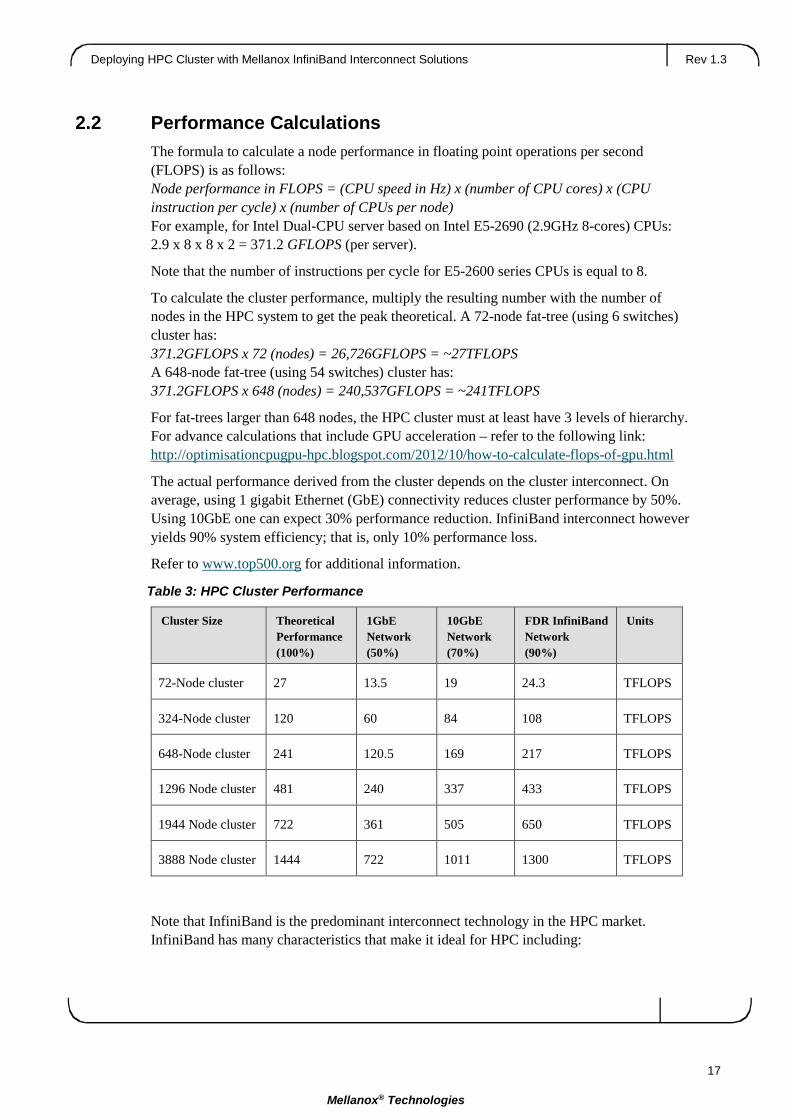
2.2 Performance Calculations The formula to calculate a node performance in floating point operations per second (FLOPS) is as follows: Node performance in FLOPS = (CPU speed in Hz) x (number of CPU cores) x (CPU instruction per cycle) x (number of CPUs per node) For example, for Intel Dual-CPU server based on Intel E5-2690 (2.9GHz 8-cores) CPUs: 2.9 x 8 x 8 x 2 = 371.2 GFLOPS (per server).
Note that the number of instructions per cycle for E5-2600 series CPUs is equal to 8.
To calculate the cluster performance, multiply the resulting number with the number of nodes in the HPC system to get the peak theoretical. A 72-node fat-tree (using 6 switches) cluster has: 371.2GFLOPS x 72 (nodes) = 26,726GFLOPS = ~27TFLOPS A 648-node fat-tree (using 54 switches) cluster has: 371.2GFLOPS x 648 (nodes) = 240,537GFLOPS = ~241TFLOPS
For fat-trees larger than 648 nodes, the HPC cluster must at least have 3 levels of hierarchy. For advance calculations that include GPU acceleration – refer to the following link: http://optimisationcpugpu-hpc.blogspot.com/2012/10/how-to-calculate-flops-of-gpu.html
The actual performance derived from the cluster depends on the cluster interconnect. On average, using 1 gigabit Ethernet (GbE) connectivity reduces cluster performance by 50%. Using 10GbE one can expect 30% performance reduction. InfiniBand interconnect however yields 90% system efficiency; that is, only 10% performance loss.
Refer to www.top500.org for additional information.
Table 3: HPC Cluster Performance
Cluster Size Theoretical Performance (100%)
1GbE Network (50%)
10GbE Network (70%)
FDR InfiniBand Network (90%)
Units
72-Node cluster 27 13.5 19 24.3 TFLOPS
324-Node cluster 120 60 84 108 TFLOPS
648-Node cluster 241 120.5 169 217 TFLOPS
1296 Node cluster 481 240 337 433 TFLOPS
1944 Node cluster 722 361 505 650 TFLOPS
3888 Node cluster 1444 722 1011 1300 TFLOPS
Note that InfiniBand is the predominant interconnect technology in the HPC market. InfiniBand has many characteristics that make it ideal for HPC including:

Rev 1.3 Designing an HPC Cluster
18
Mellanox® Technologies
• Low latency and high throughput
• Remote Direct Memory Access (RDMA)
• Flat Layer 2 that scales out to thousands of endpoints
• Centralized management
• Multi-pathing
• Support for multiple topologies
2.3 Communication Library Support To enable early and transparent adoption of the capabilities provided by Mellanox’s interconnects, Mellanox developed and supports two libraries:
• Mellanox Messaging (MXM)
• Fabric Collective Accelerator (FCA)
These are used by communication libraries to provide full support for upper level protocols (ULPs; e.g. MPI) and PGAS libraries (e.g. OpenSHMEM and UPC). Both MXM and FCA are provided as standalone libraries, with well-defined interfaces, and are used by several communication libraries to provide point-to-point and collective communication libraries. Additionally, Mellanox packages these libraries with OpenMPI, SHMEM and UPC distributions and performance profiling tools as a single download called HPC-X.
Figure 13: Communication Libraries
2.3.1 Fabric Collective Accelerator The Fabric Collective Accelerator (FCA) library provides support for MPI and PGAS collective operations. The FCA is designed with modular component architecture to facilitate the rapid deployment of new algorithms and topologies via component plugins. The FCA can take advantage of the increasingly stratified memory and network hierarchies found in current and emerging HPC systems. Scalability and extensibility are two of the primary design objectives of the FCA. As such, FCA topology plugins support hierarchies based on InfiniBand switch layout and shared memory hierarchies – both share sockets, as well as

Deploying HPC Cluster with Mellanox InfiniBand Interconnect Solutions Rev 1.3
19
Mellanox® Technologies
employ NUMA sharing. The FCA’s plugin-based implementation minimizes the time needed to support new types of topologies and hardware capabilities.
At its core, FCA is an engine that enables hardware assisted non-blocking collectives. In particular, FCA exposes CORE-Direct capabilities. With CORE-Direct, the HCA manages and progresses a collective communication operation in an asynchronous manner without CPU involvement. FCA is endowed with a CORE-Direct plugin module that supports fully asynchronous, non-blocking collective operations whose capabilities are fully realized as implementations of MPI-3 non-blocking collective routines. In addition to providing full support for asynchronous, non-blocking collective communications, FCA exposes ULPs to the HCA’s ability to perform floating-point and integer reduction operations.
Since the performance and scalability of collective communications often play a key role in the scalability and performance of many HPC scientific applications, CORE-Direct technology is introduced by Mellanox as one mechanism for addressing these issues. The offloaded capabilities can be leveraged to improve overall application performance by enabling the overlapping of communication with computation. As system sizes continue to increase, the ability to overlap communication and computational operations becomes increasingly important to improve overall system utilization, time to solution, and minimize energy consumption. This capability is also extremely important for reducing the negative effects of system noise. By using the HCA to manage and progress collective communications, process skew attributed to kernel-level interrupts and its tendency to “amplify” latency at large-scale can be minimized.
2.3.2 Mellanox Messaging The Mellanox Messaging (MXM) library provides point-to-point communication services including send/receive, RDMA, atomic operations, and active messaging. In addition to these core services, MXM also supports important features such as one-sided communication completion needed by ULPs that define one-sided communication operations such as MPI, SHMEM, and UPC. MXM supports several InfiniBand+ transports through a thin, transport agnostic interface. Supported transports include the scalable Dynamically Connected Transport (DC), Reliably Connected Transport (RC), Unreliable Datagram (UD), Ethernet RoCE, and a Shared Memory transport for optimizing on-host, latency sensitive communication. MXM provides a vital mechanism for Mellanox to rapidly introduce support for new hardware capabilities that deliver high-performance, scalable and fault-tolerant communication services to end-users.
MXM leverages communication offload capabilities to enable true asynchronous communication progress, freeing up the CPU for computation. This multi-rail, thread-safe support includes both asynchronous send/receive and RDMA modes of communication. In addition, there is support for leveraging the HCA’s extended capabilities to directly handle non-contiguous data transfers for the two aforementioned communication modes.
MXM employs several methods to provide a scalable resource foot-print. These include support for DCT, receive side flow-control, long-message Rendezvous protocol, and the so-called zero-copy send/receive protocol. Additionally, it provides support for a limited
Rev 1.3 Designing an HPC Cluster
20
Mellanox® Technologies
number of RC connections which can be used when persistent communication channels are more appropriate than dynamically created ones.
When ULPs, such as MPI, define their fault-tolerant support, MXM will fully support these features.
As mentioned, MXM provides full support for both MPI and several PGAS protocols, including OpenSHMEM and UPC. MXM also provides offloaded hardware support for send/receive, RDMA, atomic, and synchronization operations.
2.4 Quality of Service Quality of Service (QoS) requirements stem from the realization of I/O consolidation over an InfiniBand network. As multiple applications may share the same fabric, a means is needed to control their use of network resources.
The basic need is to differentiate the service levels provided to different traffic flows, such that a policy can be enforced and can control each flow-utilization of fabric resources.
The InfiniBand Architecture Specification defines several hardware features and management interfaces for supporting QoS:
• Up to 15 Virtual Lanes (VL) carry traffic in a non-blocking manner
• Arbitration between traffic of different VLs is performed by a two-priority-level weighted round robin arbiter. The arbiter is programmable with a sequence of (VL, weight) pairs and a maximal number of high priority credits to be processed before low priority is served.
• Packets carry class of service marking in the range 0 to 15 in their header SL field
• Each switch can map the incoming packet by its SL to a particular output VL, based on a programmable table VL=SL-to-VL-MAP(in-port, out-port, SL)
• The Subnet Administrator controls the parameters of each communication flow by providing them as a response to Path Record (PR) or MultiPathRecord (MPR) queries
2.5 Locating the Subnet Manager InfiniBand uses a centralized resource, called a subnet manager (SM), to handle the management of the fabric. The SM discovers new endpoints that are attached to the fabric, configures the endpoints and switches with relevant networking information, and sets up the forwarding tables in the switches for all packet-forwarding operations.
There are three options to select the best place to locate the SM:
1. Enabling the SM on one of the managed switches. This is a very convenient and quick operation. Only one command is needed to turn the SM on. This helps to make InfiniBand ‘plug & play’, one less thing to install and configure. In a blade switch environment it is common due to the following advantages:
a. Blade servers are normally expensive to allocate as SM servers; and
b. Adding non-blade (standalone rack-mount) servers dilutes the value proposition of blades (easy upgrade, simplified cabling, etc).

Deploying HPC Cluster with Mellanox InfiniBand Interconnect Solutions Rev 1.3
21
Mellanox® Technologies
2. Server-based SM would make a lot of sense for large clusters so there’s enough CPU power to cope with things such as major topology changes. Weaker CPUs can handle large fabrics but it may take a long time for the servers to come back up. In addition, there may be situations where the SM is too slow to ever catch up. Therefore, it is recommended to run the SM on a server in case there are 648 nodes or more.
3. Use Unified Fabric Management (UFM®) Appliance dedicated server. UFM offers much more than the SM. UFM needs more compute power than the existing switches have, but does not require an expensive server. It does represent additional cost for the dedicated server.
2.6 Unified Fabric Management On top of the extensive features of the hardware and subnet management capabilities, large fabrics require advanced management tools for maximizing up-time, quick handling of failures and optimizing fabric utilization – which is where the Unified Fabric Management (UFM) comes into play.
UFM’s main benefits include:
• Identifying and solving issues fast – health and performance
• Measuring fabric utilization and trends
• Identifying and analyzing congestion and bottle necks
• Efficient and centralized management of a large number of devices
• Automating configuration and provisioning tasks
• Easy integration with existing 3rd party management tools via web services API
• Easy extensibility of model and functionality
2.6.1 Dashboard The dashboard enables us to view the status of the entire fabric in one view, such as fabric health, fabric performance, congestion map, and top alerts. It provides an effective way to keep track of fabric activity, analyze the fabric behavior, and pro-actively act to display these in one window.
2.6.2 Advanced Monitoring Engine Existing management platforms provide device and port level information only. When an application/traffic issue occurs, the event is not identified and not correlated with the application layer.
UFM provides detailed monitoring of host and switch parameters. The information includes traffic characteristics, physical information, and health and error counters. That data can be aggregated from multiple devices and correlated to physical or logical objects. For example: we can get aggregated information per application, per specific fabric tenant server group, per switch ports, or any other combination of these.

Rev 1.3 Designing an HPC Cluster
22
Mellanox® Technologies
This increases visibility into traffic and device behavior through aggregated and meaningful information, correlation between switch/port information, and service level.
The monitoring history features enable historical analysis of fabric health and performance. The monitoring history database feature supports UFM Server Local database and remote database (MS SQL Database Supported for the remote database).
2.6.3 Traffic and Congestion Map UFM’s industry unique Traffic Map provides an aggregated view of the fabric health and is a powerful fabric analysis tool. The advanced view provides the only effective way to detect fabric-wide situations such as congestion spread, inefficient routing, or job placement. The administrator can therefore act to optimize the fabric by activating QoS, Traffic Optimized Routing Algorithm, changing job placement, or by adding fabric resources.
2.6.4 Health Report The UFM Fabric Health report enables the fabric administrator to get a one-click clear snapshot of the fabric. Findings are clearly displayed and marked with red, yellow, or green based on their criticality. The report comes in table and HTML format for easy distribution and follow-up.
2.6.5 Event Management UFM provides threshold-based event management for health and performance issues. Alerts are presented in the GUI and in the logs. Events can be sent via SNMP traps and also trigger rule based scripts (e.g. based on event criticality or on affected object).
The UFM reveals its advantage in advanced analysis and correlation of events. For example, events are correlated to the fabric service layer or can automatically mark nodes as faulty or healthy. This is essential for keeping a large cluster healthy and optimized at all times.
2.6.6 Central Device Management In large fabrics with tens of thousands of nodes and many switches, some managed other unmanaged, on-going device management becomes a massive operational burden: firmware upgrade needs to be done by physical access (scripts), maintenance is manual, and many hours of work and lack of traceability and reporting pose challenges.
UFM provides the ability to centrally access and perform maintenance tasks on fabric devices. UFM allows users to easily sort thousands of ports and devices and to drill down into each and every property or counter. Tasks such as port reset, disable, enable, remote device access, and firmware upgrade are initiated from one central location for one or many devices at a time.
2.6.7 Fabric Abstraction Fabric as a service model enables managing the fabric topology in an application/service oriented view. All other system functions such as monitoring and configuration are correlated with this model. Change management becomes as seamless as moving resources from one Logical Object to another – via a GUI or API.

Deploying HPC Cluster with Mellanox InfiniBand Interconnect Solutions Rev 1.3
23
Mellanox® Technologies
3 Installation
3.1 Hardware Requirements The required hardware for a 72-node InfiniBand HPC cluster is listed in Table 4.
Table 4: Required Hardware
Equipment Notes
6x MSX6036F-XXX (or MSX6025F-XXX) InfiniBand Switch.
36-port 56Gb/s InfiniBand FDR switch
72x MCX353A-FCBT InfiniBand Adapter 56Gb/s InfiniBand FDR Adapter cards
MX22071XX-XXX – passive copper MX2207310-XXX – FDR AOC
Cables: Refer to Mellanox.com for other cabling options.
3.2 Software Requirements • Refer to Mellanox® OFED for Linux Release Notes for information on the OS supported.
• OpenSM should be running on one of the servers or switches in the fabric.
• HPC-X or other MPI, SHMEM, UPC distribution should be installed.
3.3 Hardware Installation The following must be performed to physically build the interconnect portion of the cluster:
1. Install the InfiniBand HCA into each server as specified in the user manual.
2. Rack install the InfiniBand switches as specified in their switch user manual and according to the physical locations set forth in your cluster planning.
3. Cable the cluster as per the proposed topology.
a. Start with connections between the servers and the Top of Rack (ToR) switch. Connect to the server first and then to the switch, securing any extra cable length.
b. Run wires from the ToR switches to the core switches. First connect the cable to the ToR and then to the core switch, securing the extra cable lengths at the core switch end.
c. For each cable connection (server or switch), ensure that the cables are fully supported.
3.4 Driver Installation The InfiniBand software drivers and ULPs are developed and released through the Open Fabrics Enterprise Distribution (OFED) software stack. MLNX_OFED is the Mellanox version of this software stack. Mellanox bases MLNX_OFED on the OFED stack, however,

Rev 1.3 Installation
24
Mellanox® Technologies
MLNX_OFED includes additional products and documentation on top of the standard OFED offering. Furthermore, the MLNX_OFED software undergoes additional quality assurance testing by Mellanox.
All hosts in the fabric must have MLNX_OFED installed.
Perform the following steps for basic MLNX_OFED installation.
Step 1: Download MLNX_OFED from www.mellanox.com and locate it in your file system.
Step 2: 1Download the OFED .iso and run the following: # mkdir /mnt/tmp # mount –o loop MLNX_OFED_LINUX-2.0.3-0.0.0-rhel6.4-x86_64.iso /mnt/tmp # cd /mnt/tmp # ./mlnxofedinstall
Step 3: Reboot the server (if the firmware is updated).
Step 4: Verify MLNX_OFED installation. When running ibv_devinfo, you should see an output similar to this: # ibv_devinfo hca_id: mlx4_0 transport: InfiniBand (0) fw_ver: 2.30.2010 node_guid: 0002:c903:001c:6000 sys_image_guid: 0002:c903:001c:6003 vendor_id: 0x02c9 vendor_part_id: 4099 hw_ver: 0x1 board_id: MT_1090120019 phys_port_cnt: 2 port: 1 state: PORT_ACTIVE (4) max_mtu: 4096 (5) active_mtu: 4096 (5) sm_lid: 12 port_lid: 3 port_lmc: 0x00 link_layer: InfiniBand port: 2 state: PORT_DOWN (1) max_mtu: 4096 (5) active_mtu: 4096 (5) sm_lid: 0 port_lid: 0 port_lmc: 0x00 link_layer: InfiniBand
Step 5: Set up your IP address for your ib0 interface by editing the ifcfg-ib0 file and running ifup as follows: # vi /etc/sysconfig/network-scripts/ifcfg-ib0 DEVICE=ib0 BOOTPROTO=none ONBOOT="yes"
1 If your kernel version does not match any of the offered pre-built RPMs, you can add your kernel version by using the script
“mlnx_add_kernel_support.sh” located under the docs/ directory. For further information on the mlnx_add_kernel_support.sh tool, see the Mellanox OFED for Linux User Manual, Pre-installation Notes section.
Deploying HPC Cluster with Mellanox InfiniBand Interconnect Solutions Rev 1.3
25
Mellanox® Technologies
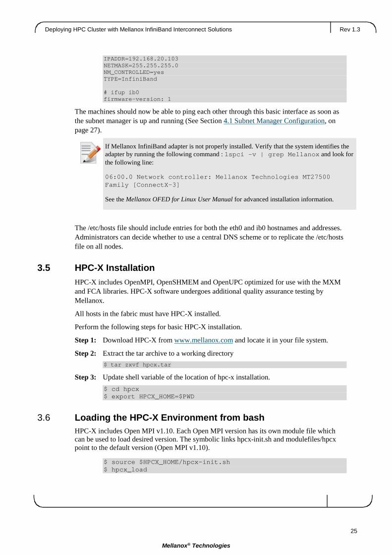
IPADDR=192.168.20.103 NETMASK=255.255.255.0 NM_CONTROLLED=yes TYPE=InfiniBand # ifup ib0 firmware-version: 1
The machines should now be able to ping each other through this basic interface as soon as the subnet manager is up and running (See Section 4.1 Subnet Manager Configuration, on page 27).
The /etc/hosts file should include entries for both the eth0 and ib0 hostnames and addresses. Administrators can decide whether to use a central DNS scheme or to replicate the /etc/hosts file on all nodes.
3.5 HPC-X Installation HPC-X includes OpenMPI, OpenSHMEM and OpenUPC optimized for use with the MXM and FCA libraries. HPC-X software undergoes additional quality assurance testing by Mellanox.
All hosts in the fabric must have HPC-X installed.
Perform the following steps for basic HPC-X installation.
Step 1: Download HPC-X from www.mellanox.com and locate it in your file system.
Step 2: Extract the tar archive to a working directory $ tar zxvf hpcx.tar
Step 3: Update shell variable of the location of hpc-x installation. $ cd hpcx $ export HPCX_HOME=$PWD
3.6 Loading the HPC-X Environment from bash HPC-X includes Open MPI v1.10. Each Open MPI version has its own module file which can be used to load desired version. The symbolic links hpcx-init.sh and modulefiles/hpcx point to the default version (Open MPI v1.10).
$ source $HPCX_HOME/hpcx-init.sh $ hpcx_load
If Mellanox InfiniBand adapter is not properly installed. Verify that the system identifies the adapter by running the following command : lspci –v | grep Mellanox and look for the following line:
06:00.0 Network controller: Mellanox Technologies MT27500 Family [ConnectX-3]
See the Mellanox OFED for Linux User Manual for advanced installation information.

Rev 1.3 Installation
26
Mellanox® Technologies
$ env | grep HPCX $ mpirun -np 2 $HPCX_MPI_TESTS_DIR/examples/hello_usempi $ oshrun -np 2 $HPCX_MPI_TESTS_DIR/examples/hello_oshmem $ hpcx_unload
3.7 Loading the HPC-X Environment from Modules To load Open MPI/OpenSHMEM v1.10 based package:
$ module use $HPCX_HOME/modulefiles $ module load hpcx
The instrumentation can be applied on a per-collective basis, and is controlled by the following environment variables:
$ export IPM_ADD_BARRIER_TO_REDUCE=1 $ export IPM_ADD_BARRIER_TO_ALLREDUCE=1 $ export IPM_ADD_BARRIER_TO_GATHER=1 $ export IPM_ADD_BARRIER_TO_ALL_GATHER=1 $ export IPM_ADD_BARRIER_TO_ALLTOALL=1 $ export IPM_ADD_BARRIER_TO_ALLTOALLV=1 $ export IPM_ADD_BARRIER_TO_BROADCAST=1 $ export IPM_ADD_BARRIER_TO_SCATTER=1 $ export IPM_ADD_BARRIER_TO_SCATTERV=1 $ export IPM_ADD_BARRIER_TO_GATHERV=1 $ export IPM_ADD_BARRIER_TO_ALLGATHERV=1 $ export IPM_ADD_BARRIER_TO_REDUCE_SCATTER=1
By default, all values are set to '0'.

Deploying HPC Cluster with Mellanox InfiniBand Interconnect Solutions Rev 1.3
27
Mellanox® Technologies
4 Configuration
4.1 Subnet Manager Configuration The MLNX_OFED stack comes with a subnet manager called OpenSM. OpenSM must be run on at least one server or managed switch attached to the fabric to function. Note that there are other options in addition to OpenSM. One option is to use the Mellanox® high-end fabric management tool, UFM®, which also includes a “built-in” subnet manager.
OpenSM is installed by default once MLNX_OFED is installed.
4.1.1 Configuring the SM on a Server • To start up OpenSM on a server, simply run opensm from the command line on your
management node by typing: opensm
Or:
• Start OpenSM automatically on the head node by editing the /etc/opensm/opensm.conf file.
Create a configuration file by running opensm –config /etc/opensm/opensm.conf
Edit the file with the following line: onboot=yes
Upon initial installation, OpenSM is configured and running with a default routing algorithm. When running a multi-tier fat-tree cluster, it is recommended to change the following options to create the most efficient routing algorithm delivering the highest performance: –routing_engine=updn
For full details on other configurable attributes of OpenSM, see the “OpenSM – Subnet Manager” chapter of the Mellanox OFED for Linux User Manual.
4.1.2 Configuring the SM on a Switch MLNX-OS® or FabricIT™ software runs on all Mellanox switch systems.
To enable the SM on one of the managed switches follow the next steps
1. Login to the switch and enter to config mode: switch (config)#
2. Run the command: switch (config)#ib sm switch (config)#
3. Check if the SM is running. Run: switch (config)#show ib sm enable

Rev 1.3 Configuration
28
Mellanox® Technologies
switch (config)#

Deploying HPC Cluster with Mellanox InfiniBand Interconnect Solutions Rev 1.3
29
Mellanox® Technologies
5 Verification & Testing Now that the driver is loaded properly, the network interfaces over InfiniBand (ib0, ib1) are created, and the Subnet Manager is running, it is time to test the cluster with some basic operations and data transfers.
5.1 Verifying End-Node is Up and Running The first thing is to assure that the driver is running on all of the compute nodes and that the link is up on the InfiniBand port(s) of these nodes.
To do this, use the ibstat command by typing:
ibstat
You should see a similar output to the following: CA 'mlx4_0' CA type: MT4099 Number of ports: 2 Firmware version: 2.30.2100 Hardware version: 1 Node GUID: 0x0002c90300eff4b0 System image GUID: 0x0002c90300eff4b3 Port 1: State: Active Physical state: LinkUp Rate: 56 Base lid: 12 LMC: 0 SM lid: 12 Capability mask: 0x0251486a Port GUID: 0x0002c90300eff4b1 Link layer: InfiniBand Port 2: State: Down Physical state: Disabled Rate: 10 Base lid: 0 LMC: 0 SM lid: 0 Capability mask: 0x02514868 Port GUID: 0x0002c90300eff4b2 Link layer: InfiniBand
5.1.1 Debug Recommendation If there is no output displayed from the ibstat command, it most likely is an indication that the driver is not loaded. Check /var/log/messages for clues as to why the driver did not load properly.

Rev 1.3 Verification & Testing
30
Mellanox® Technologies
5.2 Verifying Cluster Connectivity The next step is verifying the connectivity of the cluster. Identify, troubleshoot, and address any bad connections. This is accomplished as follows:
Step 1: Verify that the topology is properly wired. See Section 5.3 Verifying Cluster Topology on page 5.330.
Step 2: Verify that the physical interconnect is running at an acceptable BER (bit error rate). See Section 5.4 Verifying Physical Interconnect is Running at Acceptable BER on page 5.4.
Step 3: Stress the cluster. See Section 5.6 Stress Cluster on page 5.6.
Step 4: Re-verify that the physical interconnect is error-free.
Step 5: In many instances, Steps 3 and 4 above are an iterative process and should be performed multiple times until the cluster interconnect is completely validated.
5.3 Verifying Cluster Topology Verifying that the cluster is wired according to the designed topology can actually be accomplished in a number of ways. One fairly straightforward methodology is to run and review the output of the ibnetdiscover tool.
This tool performs InfiniBand subnet discovery and outputs a topology file. GUIDs, node type, and port numbers are displayed, as well as port LIDs and node descriptions. All nodes and associated links are displayed. The topology file format shows the connectivity by displaying on the left the port number of the current node, and on the right the peer node (node at the other end of the link). The active link width and speed are then appended to the end of the line.
The following is an example output:
# Topology file: generated on Wed Mar 27 17:36:55 2013 # # Initiated from node 0002c903001a4350 port 0002c903001a4350 vendid=0x2c9 devid=0xc738 sysimgguid=0x2c903008e4900 switchguid=0x2c903008e4900(2c903008e4900) Switch 36 "S-0002c903008e4900" # "MF0;switch-b7a300:SX60XX/U1" enhanced port 0 lid 3 lmc 0 [1] "H-0002c903001a42a0"[1](2c903001a42a0) # "jupiter002 HCA-1" lid 17 4xFDR [2] "H-0002c903001a4320"[1](2c903001a4320) # "jupiter005 HCA-1" lid 5 4xFDR [3] "H-0002c903001a42d0"[1](2c903001a42d0) # "jupiter003 HCA-1" lid 24 4xFDR [4] "H-0002c903001a43a0"[1](2c903001a43a0) # "jupiter008 HCA-1" lid 18 4xFDR [5] "H-0002c903001a4280"[1](2c903001a4280) # "jupiter007 HCA-1" lid 13 4xFDR [6] "H-0002c903001a4350"[1](2c903001a4350) # "jupiter001 HCA-1" lid 1 4xFDR [7] "H-0002c903001a4300"[1](2c903001a4300) # "jupiter004 HCA-1" lid 2 4xFDR [8] "H-0002c903001a4330"[1](2c903001a4330) # "jupiter006 HCA-1" lid 6 4xFDR

Deploying HPC Cluster with Mellanox InfiniBand Interconnect Solutions Rev 1.3
31
Mellanox® Technologies
Ca 2 "H-0002c90300e69b30" # "jupiter020 HCA-1" [1](2c90300e69b30) "S-0002c903008e4900"[32] # lid 8 lmc 0 "MF0;switch-b7a300:SX60XX/U1" lid 3 4xFDR vendid=0x2c9 devid=0x1011 sysimgguid=0x2c90300e75290 caguid=0x2c90300e75290 Ca 2 "H-0002c90300e75290" # "jupiter017 HCA-1" [1](2c90300e75290) "S-0002c903008e4900"[31] # lid 16 lmc 0 "MF0;switch-b7a300:SX60XX/U1" lid 3 4xFDR vendid=0x2c9 devid=0x1011 sysimgguid=0x2c90300e752c0 caguid=0x2c90300e752c0 Ca 2 "H-0002c90300e752c0" # "jupiter024 HCA-1" [1](2c90300e752c0) "S-0002c903008e4900"[30] # lid 23 lmc 0 "MF0;switch-b7a300:SX60XX/U1" lid 3 4xFDR
NOTE: The following additional information is also output from the command. The output example has been truncated for the illustrative purposes of this document.
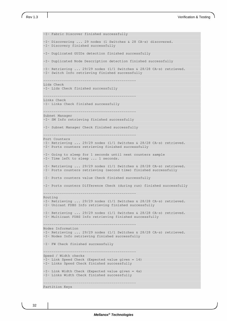
5.4 Verifying Physical Interconnect is Running at Acceptable BER The next step is to check the health of the fabric, including any bad cable connections, bad cables, and so on. For further details on ibdiagnet, see Mellanox® OFED for Linux User Manual.
The command ibdiagnet –ls 14 –lw 4x –r checks the fabric connectivity to ensure that all links are running at FDR rates (14Gb/s per lane), all ports are 4x port width, and runs a detailed report on the health of the cluster, including excessive port error counters beyond the defined threshold.
For help with the ibdiagnet command parameters, type: ibdiagnet –help
If any ports have excessive port errors, the cable connections, or the cables themselves should be carefully examined for any issues.
Load Plugins from: /usr/share/ibdiagnet2.1.1/plugins/ (You can specify more paths to be looked in with "IBDIAGNET_PLUGINS_PATH" env variable) Plugin Name Result Comment libibdiagnet_cable_diag_plugin Succeeded Plugin loaded libibdiagnet_cable_diag_plugin-2.1.1 Failed Plugin options issue - Option "get_cable_info" from requester "Cable Diagnostic (Plugin)" already exists in requester "Cable Diagnostic (Plugin)" --------------------------------------------- Discovery -I- Discovering ... 29 nodes (1 Switches & 28 CA-s) discovered.
Rev 1.3 Verification & Testing
32
Mellanox® Technologies
-I- Fabric Discover finished successfully -I- Discovering ... 29 nodes (1 Switches & 28 CA-s) discovered. -I- Discovery finished successfully -I- Duplicated GUIDs detection finished successfully -I- Duplicated Node Description detection finished successfully -I- Retrieving ... 29/29 nodes (1/1 Switches & 28/28 CA-s) retrieved. -I- Switch Info retrieving finished successfully --------------------------------------------- Lids Check -I- Lids Check finished successfully --------------------------------------------- Links Check -I- Links Check finished successfully --------------------------------------------- Subnet Manager -I- SM Info retrieving finished successfully -I- Subnet Manager Check finished successfully --------------------------------------------- Port Counters -I- Retrieving ... 29/29 nodes (1/1 Switches & 28/28 CA-s) retrieved. -I- Ports counters retrieving finished successfully -I- Going to sleep for 1 seconds until next counters sample -I- Time left to sleep ... 1 seconds. -I- Retrieving ... 29/29 nodes (1/1 Switches & 28/28 CA-s) retrieved. -I- Ports counters retrieving (second time) finished successfully -I- Ports counters value Check finished successfully -I- Ports counters Difference Check (during run) finished successfully --------------------------------------------- Routing -I- Retrieving ... 29/29 nodes (1/1 Switches & 28/28 CA-s) retrieved. -I- Unicast FDBS Info retrieving finished successfully -I- Retrieving ... 29/29 nodes (1/1 Switches & 28/28 CA-s) retrieved. -I- Multicast FDBS Info retrieving finished successfully --------------------------------------------- Nodes Information -I- Retrieving ... 29/29 nodes (1/1 Switches & 28/28 CA-s) retrieved. -I- Nodes Info retrieving finished successfully -I- FW Check finished successfully --------------------------------------------- Speed / Width checks -I- Link Speed Check (Expected value given = 14) -I- Links Speed Check finished successfully -I- Link Width Check (Expected value given = 4x) -I- Links Width Check finished successfully --------------------------------------------- Partition Keys

Deploying HPC Cluster with Mellanox InfiniBand Interconnect Solutions Rev 1.3
33
Mellanox® Technologies
-I- Retrieving ... 29/29 nodes (1/1 Switches & 28/28 CA-s) retrieved. -I- Partition Keys retrieving finished successfully -I- Partition Keys finished successfully --------------------------------------------- Alias GUIDs -I- Retrieving ... 29/29 nodes (1/1 Switches & 28/28 CA-s) retrieved. -I- Alias GUIDs retrieving finished successfully -I- Alias GUIDs finished successfully --------------------------------------------- Summary -I- Stage Warnings Errors Comment -I- Discovery 0 0 -I- Lids Check 0 0 -I- Links Check 0 0 -I- Subnet Manager 0 0 -I- Port Counters 0 0 -I- Routing 0 0 -I- Nodes Information 0 0 -I- Speed / Width checks 0 0 -I- Partition Keys 0 0 -I- Alias GUIDs 0 0 -I- You can find detailed errors/warnings in: /var/tmp/ibdiagnet2/ibdiagnet2.log -I- ibdiagnet database file : /var/tmp/ibdiagnet2/ibdiagnet2.db_csv -I- LST file : /var/tmp/ibdiagnet2/ibdiagnet2.lst -I- Subnet Manager file : /var/tmp/ibdiagnet2/ibdiagnet2.sm -I- Ports Counters file : /var/tmp/ibdiagnet2/ibdiagnet2.pm -I- Unicast FDBS file : /var/tmp/ibdiagnet2/ibdiagnet2.fdbs -I- Multicast FDBS file : /var/tmp/ibdiagnet2/ibdiagnet2.mcfdbs -I- Nodes Information file : /var/tmp/ibdiagnet2/ibdiagnet2.nodes_info -I- Partition keys file : /var/tmp/ibdiagnet2/ibdiagnet2.pkey -I- Alias guids file : /var/tmp/ibdiagnet2/ibdiagnet2.aguid
5.4.1 Debug Recommendation Running ‘ibdiagnet –pc clears all port counters.
Running ibdiagnet –P all=1 reports any error counts greater than 0 that occurred since the last port reset.
For an HCA with dual ports, by default, ibdiagnet scans only the primary port connections.
Symbol Rate Error Criteria: It is acceptable for any link to have less than 10 symbol errors per hour.
5.5 Running Basic Performance Tests The MLNX_OFED stack has a number of low level performance benchmarks built in. See the “Performance” chapter in Mellanox OFED for Linux User Manual for additional information.

Rev 1.3 Verification & Testing
34
Mellanox® Technologies
5.6 Stress Cluster Once the fabric has been cleaned, it should be stressed with data on the links. Rescan the fabric for any link errors. The best way to do this is to run MPI between all of the nodes using a network-based benchmark that uses all-all collectives, such as Intel IMB Benchmark. It is recommended to run this for an hour to properly stress the cluster.
Step 1: Reset all the port counters in the fabric. Run: # ibdiagnet –pc
Step 2: Run the benchmark using: # /usr/mpi/gcc/mvapich-<mvapich-ver>/bin/mpirun_rsh –np <cluster node count> \ -hostfile /home/<username>/cluster \ /usr/mpi/gcc/mvapich-<mvapich-ver>/tests/IMB-<IMB-ver>/IMB-MPI1
#--------------------------------------------------- # Intel (R) MPI Benchmark Suite V3.0, MPI-1 part #--------------------------------------------------- # Date : Sun Mar 2 19:56:42 2008 # Machine : x86_64 # System : Linux # Release : 2.6.16.21-0.8-smp # Version : #1 SMP Mon Jul 3 18:25:39 UTC 2006 # MPI Version : 1.2 # MPI Thread Environment: MPI_THREAD_FUNNELED # # Minimum message length in bytes: 0 # Maximum message length in bytes: 4194304 # MPI_Datatype for reductions : MPI_FLOAT # MPI_Op : MPI_SUM # # # List of Benchmarks to run: # PingPong # PingPing # Sendrecv # Exchange # Allreduce # Reduce # Reduce_scatter # Allgather # Allgatherv # Alltoall # Alltoallv # Bcast # Barrier #--------------------------------------------------- # Benchmarking PingPong # #processes = 2 #--------------------------------------------------- #bytes #repetitions t[usec] Mbytes/sec 0 1000 1.25 0.00 1 1000 1.24 0.77 2 1000 1.25 1.52 4 1000 1.23 3.09 8 1000 1.26 6.07 16 1000 1.29 11.83 32 1000 1.36 22.51 64 1000 1.52 40.25 128 1000 2.67 45.74 256 1000 3.03 80.48 512 1000 3.64 134.22

Deploying HPC Cluster with Mellanox InfiniBand Interconnect Solutions Rev 1.3
35
Mellanox® Technologies
1024 1000 4.89 199.69 2048 1000 6.30 309.85 4096 1000 8.91 438.24 8192 1000 14.07 555.20 16384 1000 18.85 828.93 32768 1000 30.47 1025.75 65536 640 53.67 1164.57 131072 320 99.78 1252.80 262144 160 191.80 1303.44 524288 80 373.92 1337.19 1048576 40 742.31 1347.14 2097152 20 1475.20 1355.75 4194304 10 2956.95 1352.75 #-- OUTPUT TRUNCATED
This test should be run across all nodes in the cluster, with a single entry for each node in the host file.
After the MPI test runs successfully, rescan the fabric using ibdiagnet –P all=1, which will check for any port error counts that occurred during the test.
This process should be repeated enough to ensure completely error-free results from the port error scans.

Rev 1.3 Verification & Testing
36
Mellanox® Technologies
Appendix A: Best Practices
A.1 Cabling Cables should be treated with caution. Please follow the guidelines listed in the following subsections.
A.1.1 General Rules • Do not kink cables
• Do not bend cables beyond the recommended minimum radius
• Do not twist cables
• Do not stand on or roll equipment over the cables
• Do not step or stand over the cables
• Do not lay cables on the floor
• Make sure that you are easily able to replace any leaf in the switch if need be
• Do not uncoil the cable, as a kink might occur. Hold the coil closed as you unroll the cable, pausing to allow the cable to relax as it is unrolled.
• Do not step on the cable or connectors
• Plan cable paths away from foot
• Do not pull the cable out of the shipping box, through any opening, or around any corners. Unroll the cable as you lay it down and move it through turns.
• Do not twist the cable to open a kink. If it is not severe, open the kink by unlooping the cable.
• Do not pack the cable to fit a tight space. Use an alternative cable route.
• Do not hang the cable for a length of more than 2 meters (7 feet). Minimize the hanging weight with intermediate retention points.
• Lay cables in trays as much as possible
• Do not drop the cable or connectors from any height. Gently set the cable down, resting the cable connectors on a stable surface.
• Do not cinch the cable with hard fasteners or cable ties. Use soft hook-and-loop fasteners or Velcro ties for bundling and securing cables.
• Do not drag the cable or its connectors over any surface. Carry the entire cable to and from the points of connection.
• Do not force the cable connector into the receptacle by pushing on the cable. Apply connection or disconnection forces at the connector only.

Deploying HPC Cluster with Mellanox InfiniBand Interconnect Solutions Rev 1.3
37
Mellanox® Technologies
A.1.2 Zero Tolerance for Dirt • With fiber optics, the tolerance of dirt is near zero. Airborne particles are about the size of
the core of Single Mode fiber; they absorb a lot of light and may scratch connectors if not removed.
• Try to work in a clean area. Avoid working around heating outlets, as they blow a significant amount of dust.
• Dirt on connectors is the biggest cause of scratches on polished connectors and high loss measurements
• Always keep dust caps on connectors, bulkhead splices, patch panels or anything else that is going to have a connection made with it
A.1.3 Installation Precautions • Avoid over-bundling the cables or placing multiple bundles on top of each other. This can
degrade performance of the cables underneath.
• Keep copper and fiber runs separated
• Do not place cables and bundles where they may block other equipment
• Install spare cables for future replacement of bad cables – 2 per 100 cables
• Do not bend the cable beyond its recommended radius. Ensure that cable turns are as wide as possible.
• Do not staple the cables
• Color code the cable ties, colors should indicate the endpoints. Place labels at both ends, as well as along the run.
• Test every cable as it is installed. Connect both ends and make sure that it has a physical and logical link before connecting the next one.
• Locate the main cabling distribution area in the middle of the data center
• Avoid placing copper cables near equipment that may generate high levels of electromagnetic interference
• Avoid runs near power cords, fluorescent lights, building electrical cables, and fire prevention components
• Avoid routing cables through pipes and holes since this may limit additional future cable runs
A.1.4 Daily Practices • Avoid exposing cables to direct sunlight and areas of condensation
• Do not mix 50 micron core diameter cables with 62.5 micron core diameter cables on a link
• When possible, remove abandoned cables that can restrict air flow causing overheating

Rev 1.3 Verification & Testing
38
Mellanox® Technologies
• Bundle cables together in groups of relevance (for example ISL cables and uplinks to core devices). This aids in management and troubleshooting.
• Use cables of the correct length. Leave only a little slack at each end. Keep cable runs under 90% of the max distance supported for each media type as specified in the relevant standard.
• Use Velcro based ties every 12" (30cm) to 24" (60cm)
Figure 14: Cabling
A.2 Labeling
A.2.1 Cable Labeling Labeling all cables between the leaf and the core switches is highly recommended. Failure to label the leaf-core cables hampers efforts to isolate, identify, and troubleshoot any potentially faulty cables when the cluster is deployed.
It is recommended that server nodes to leaf switch ports are labeled as detailed in Table 5.

Deploying HPC Cluster with Mellanox InfiniBand Interconnect Solutions Rev 1.3
39
Mellanox® Technologies
Table 5: Recommended Cable Labeling
Cable Location Labeling on the First End Labeling on the Other End
Node – Leaf 1. Node Name 2. Leaf# / Slot# / Port#
1. Leaf# / Slot# / Port# 2. Node Name
Leaf – Spine 1. Leaf# / Slot# / Port# 2. Spine# / Slot# / Port#
1. Spine# / Slot# / Port# 2. Leaf# / Slot# / Port#
A.2.2 Node Labeling It is important that all nodes in the cluster are individually named and labeled in a way that uniquely identifies them. There are several options for node naming; numerically, based on the size of the cluster (for example, node1023); physically, based on rack number (for example, nodeR10S5, for Rack10, Slot5); or topologically, based on location (for example, nodeL7P10, for leaf switch 7 port 10). There are advantages and disadvantages to each option.
One major reason to suggest numerical naming is that it allows for parallel commands to be run across the cluster. For instance, the PDSH utility allows for the execution of a command on multiple remote hosts in parallel.
It is recommended to name the servers with consecutive names relative to the servers’ location. Name all servers on the same switch with running consecutive names and continue with the next group on the following switch. This ensures that the MPI job schedule uses the servers in this order and utilizes the cluster better.

Rev 1.3 Verification & Testing
40
Mellanox® Technologies
Appendix B: Ordering Information Mellanox® offers the variety of switch systems, adapter cards and cables. Depending on the topology one may select the most suitable hardware.
Table 6: Ordering Information
Equipment Notes
Switch systems Refer to Mellanox.com on: http://www.mellanox.com/page/switch_systems_overview
Adapters cards Refer to Mellanox.com on: http://www.mellanox.com/page/infiniband_cards_overview
Cables and Modules Refer to Mellanox.com on: http://www.mellanox.com/page/cables
Please refer to the Mellanox Products Approved Cable Lists document for the list of supported cables.