Deploying Brocade Mobility Products with the Brocade...
16
ENTERPRISE & MOBILITY Deploying Brocade Mobility Products with the Brocade FastIron CX Series Step-by-step guide from unpacking Brocade Mobility controllers and access points to configuring devices and setting up wireless connectivity.
Transcript of Deploying Brocade Mobility Products with the Brocade...
ENTERPRISE & MOBILITY
Deploying Brocade Mobility Products with the Brocade FastIron CX Series Step-by-step guide from unpacking Brocade Mobility controllers and access points to configuring devices and setting up wireless connectivity.

ENTERPRISE & MOBILITY DEPLOYMENT GUIDE
Deploying Brocade Mobility Products with the Brocade FastIron CX Series Page 2 of 16
CONTENTS Brocade Products Overview ......................................................................................................................................................................................................... 3
Design Example ............................................................................................................................................................................................................................... 6
Server Requirements ..................................................................................................................................................................................................................... 6
What’s in the Box ............................................................................................................................................................................................................................. 7
Configuring Windows Services ................................................................................................................................................................................................... 8
Step 1: Set up DNS ................................................................................................................................................ 8
Step 2: Set up DHCP .............................................................................................................................................. 8
Step 3: Configure IE for RFS7000 and AP Web wervers ...................................................................................... 8
Configuring the Brocade FCX 624S-HPOE Switch ............................................................................................................................................................... 8
Step 1: Provide power to the switch ...................................................................................................................... 8
Step 2: Connect to the console port interface ...................................................................................................... 8
Step 3: Basic switch configuration ........................................................................................................................ 8
Step 4: Configure VLANs ........................................................................................................................................ 9
Step 5: Configure Interfaces for POE .................................................................................................................. 10
Configuring the Brocade RFS7000 Controller..................................................................................................................................................................... 10
Step 1: Provide power to the controller............................................................................................................... 10
Step 2: Set up the controller console port .......................................................................................................... 10
Step 3: Set the IP address for the controller ...................................................................................................... 10
Step 4: Basic controller configuration ................................................................................................................. 11
Configuring Access Points .......................................................................................................................................................................................................... 13
Brocade AP300 ............................................................................................................................................................ 13
Step 1: Find the AP300 MAC address ................................................................................................................. 13
Step 2: Provide power to the AP300 ................................................................................................................... 13
Step 3: Adopt AP300 in RFS7000 ....................................................................................................................... 14
Brocade AP7131/AP5181 .......................................................................................................................................... 14
Step 1: Provide power to the access point ......................................................................................................... 14
Step 2: Connect to the console using these console terminal settings ............................................................ 14
Step 3: Set the IP address ................................................................................................................................... 14
Step 4: Configuring controller pairing (DHCP not used) ..................................................................................... 15
Step 5: Adopt AP7131 in the RFS7000 .............................................................................................................. 16

ENTERPRISE & MOBILITY DEPLOYMENT GUIDE
Deploying Brocade Mobility Products with the Brocade FastIron CX Series Page 3 of 16
BROCADE PRODUCTS OVERVIEW Brocade FastIron CX Series: FCX624S-HPOE
• Compact 1U form factor
• 24 or 48 10/100/1000 Mbps RJ-45 ports, with or without PoE/PoE+
• Four GbE SFP combo ports
• Two optional 10 GbE XFP ports
• DB9 console port for management
• LEDs for port status, stack member ID, and more
• 16 dedicated GbE stacking ports
• Optional second hot-swappable, redundant power supply
• Replaceable fan unit providing side-to-rear airflow
• 10/100/1000 out-of-band management port
RFS6000 Controller
• Mid to large enterprises
• 48 Access Points (APs) per switch
• 256 Adptive Access Points (AAPs) per switch
• 576 APs per cluster
• 3,072 AAPs per cluster
• Expansion slots for 3G/4G wireless backhaul and voice
• 2,000 – 20,000 users

ENTERPRISE & MOBILITY DEPLOYMENT GUIDE
Deploying Brocade Mobility Products with the Brocade FastIron CX Series Page 4 of 16
RFS7000 Controller
• Large enterprises and data centers
• 256 Access Points (APs) per switch
• 1,024 AAPs per switch
• 3,072 APs per cluster
• 12,280,072 AAPs per cluster
• 8,000 – 96,000 users
For both controllers, clustering provides:
• Seamless Layer 2/3 mobility between RF switches
• Smart license sharing
• Dynamic AP load balancing
• AP steering
• High Availability (HA) during RF switch/network failure (manual or automatic reversion)
• Increased aggregate throughput/scaling
Centralized configuration is performed via a cluster Command-Line Interface (CLI) and Web interface
State information exchange is provided for:
• AP and MU distribution
• Identify unauthorized APs
• Smart RF
• Integrated DHCP
Brocade Mobility AP300
• Thin indoor access point
• Single 802.11b/g or dual-band 802.11a/b/g radios
• External antenna support
• Deployed with a centralized wireless controller
• WIPS sensor mode
Brocade Mobility AP7131
• Full-feature indoor access point
• Dual-band 802.11a/b/g/n radios
• Standalone or distributed with a centralized wireless controller
• Wireless mesh support
• WIPS sensor mode

ENTERPRISE & MOBILITY DEPLOYMENT GUIDE
Deploying Brocade Mobility Products with the Brocade FastIron CX Series Page 5 of 16
Brocade Mobility AP5181
• Full-feature, hardened access point
• Designed for harsh environments
• Dual-band 802.11a/b/g radios
• External antenna support
• Standalone or distributed with a centralized wireless controller
• Wireless mesh support
• WIPS sensor mode
Motorola AirDefense
• Centralized, hardened appliance
• Protection for WLAN infrastructure and devices
• Secure Layer 3 connections between sensors and appliance
• Minimal WAN bandwidth needed by sensors: less than 3 Kbps
• Two types of sensors
- Dedicated sensors are separate devices; use one for every 3 to 5 APs
- Integrated sensors are built into Brocade Mobility access points
• All sensors provide 24x7 protection for gap-free security
NOTE: In the illustration, red is used to flag a rogue AP.
Corporate Office
Dedicatedsensor Central
appliance
Field Office
IntegratedAP/Sensor
Network

ENTERPRISE & MOBILITY DEPLOYMENT GUIDE
Deploying Brocade Mobility Products with the Brocade FastIron CX Series Page 6 of 16
DESIGN EXAMPLE
SERVER REQUIREMENTS Hardware:
• Windows Server 2003, 2008, or XP
• Intel Dual CPU Core2 duo 2.4GHz or equivalent
• 4 GB memory
• 40 GB disk space
System Services:
• DHCP Server
• Domain Name Server (DNS)
• Microsoft Explorer
• Mozilla Firefox
• Console Port
• Ethernet connectivity
ENTERPRISE & MOBILITY DEPLOYMENT GUIDE
Deploying Brocade Mobility Products with the Brocade FastIron CX Series Page 7 of 16
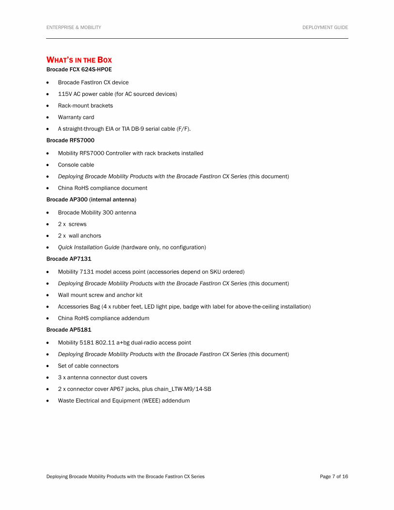
WHAT’S IN THE BOX Brocade FCX 624S-HPOE
• Brocade FastIron CX device
• 115V AC power cable (for AC sourced devices)
• Rack-mount brackets
• Warranty card
• A straight-through EIA or TIA DB-9 serial cable (F/F).
Brocade RFS7000
• Mobility RFS7000 Controller with rack brackets installed
• Console cable
• Deploying Brocade Mobility Products with the Brocade FastIron CX Series (this document)
• China RoHS compliance document
Brocade AP300 (internal antenna)
• Brocade Mobility 300 antenna
• 2 x screws
• 2 x wall anchors
• Quick Installation Guide (hardware only, no configuration)
Brocade AP7131
• Mobility 7131 model access point (accessories depend on SKU ordered)
• Deploying Brocade Mobility Products with the Brocade FastIron CX Series (this document)
• Wall mount screw and anchor kit
• Accessories Bag (4 x rubber feet, LED light pipe, badge with label for above-the-ceiling installation)
• China RoHS compliance addendum
Brocade AP5181
• Mobility 5181 802.11 a+bg dual-radio access point
• Deploying Brocade Mobility Products with the Brocade FastIron CX Series (this document)
• Set of cable connectors
• 3 x antenna connector dust covers
• 2 x connector cover AP67 jacks, plus chain_LTW-M9/14-SB
• Waste Electrical and Equipment (WEEE) addendum
ENTERPRISE & MOBILITY DEPLOYMENT GUIDE
Deploying Brocade Mobility Products with the Brocade FastIron CX Series Page 8 of 16
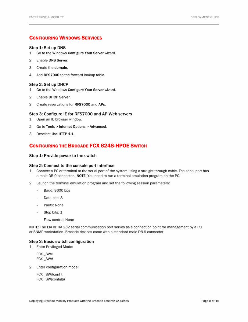
CONFIGURING WINDOWS SERVICES
Step 1: Set up DNS 1. Go to the Windows Configure Your Server wizard.
2. Enable DNS Server.
3. Create the domain.
4. Add RFS7000 to the forward lookup table.
Step 2: Set up DHCP 1. Go to the Windows Configure Your Server wizard.
2. Enable DHCP Server.
3. Create reservations for RFS7000 and APs.
Step 3: Configure IE for RFS7000 and AP Web servers 1. Open an IE browser window.
2. Go to Tools > Internet Options > Advanced.
3. Deselect Use HTTP 1.1.
CONFIGURING THE BROCADE FCX 624S-HPOE SWITCH
Step 1: Provide power to the switch
Step 2: Connect to the console port interface 1. Connect a PC or terminal to the serial port of the system using a straight-through cable. The serial port has
a male DB-9 connector. NOTE: You need to run a terminal emulation program on the PC.
2. Launch the terminal emulation program and set the following session parameters:
- Baud: 9600 bps
- Data bits: 8
- Parity: None
- Stop bits: 1
- Flow control: None
NOTE: The EIA or TIA 232 serial communication port serves as a connection point for management by a PC or SNMP workstation. Brocade devices come with a standard male DB-9 connector
Step 3: Basic switch configuration 1. Enter Privileged Mode:
FCX _SW> FCX _SW#
2. Enter configuration mode:
FCX _SW#conf t FCX _SW(config)#
ENTERPRISE & MOBILITY DEPLOYMENT GUIDE
Deploying Brocade Mobility Products with the Brocade FastIron CX Series Page 9 of 16
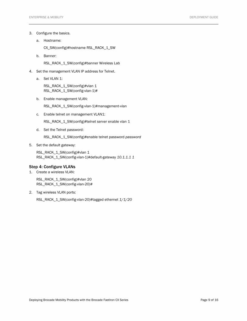
3. Configure the basics.
a. Hostname:
CX_SW(config)#hostname RSL_RACK_1_SW
b. Banner:
RSL_RACK_1_SW(config)#banner Wireless Lab
4. Set the management VLAN IP address for Telnet.
a. Set VLAN 1:
RSL_RACK_1_SW(config)#vlan 1 RSL_RACK_1_SW(config-vlan-1)#
b. Enable management VLAN:
RSL_RACK_1_SW(config-vlan-1)#management-vlan
c. Enable telnet on management VLAN1:
RSL_RACK_1_SW(config)#telnet server enable vlan 1
d. Set the Telnet password:
RSL_RACK_1_SW(config)#enable telnet password password
5. Set the default gateway:
RSL_RACK_1_SW(config)#vlan 1 RSL_RACK_1_SW(config-vlan-1)#default-gateway 10.1.1.1 1
Step 4: Configure VLANs 1. Create a wireless VLAN:
RSL_RACK_1_SW(config)#vlan 20 RSL_RACK_1_SW(config-vlan-20)#
2. Tag wireless VLAN ports:
RSL_RACK_1_SW(config-vlan-20)#tagged ethernet 1/1/20
ENTERPRISE & MOBILITY DEPLOYMENT GUIDE
Deploying Brocade Mobility Products with the Brocade FastIron CX Series Page 10 of 16
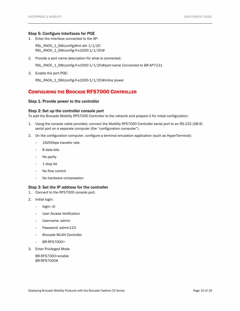
Step 5: Configure Interfaces for POE 1. Enter the interface connected to the AP:
RSL_RACK_1_SW(config)#int eth 1/1/20 RSL_RACK_1_SW(config-if-e1000-1/1/20)#
2. Provide a port name description for what is connected:
RSL_RACK_1_SW(config-if-e1000-1/1/20)#port-name Connected to BR-AP7131
3. Enable the port POE:
RSL_RACK_1_SW(config-if-e1000-1/1/20)#inline power
CONFIGURING THE BROCADE RFS7000 CONTROLLER
Step 1: Provide power to the controller
Step 2: Set up the controller console port To add the Brocade Mobility RFS7000 Controller to the network and prepare it for initial configuration:
1. Using the console cable provided, connect the Mobility RFS7000 Controller serial port to an RS-232 (DB-9) serial port on a separate computer (the “configuration computer”).
2. On the configuration computer, configure a terminal emulation application (such as HyperTerminal):
- 19200bps transfer rate
- 8 data bits
- No parity
- 1 stop bit
- No flow control
- No hardware compression
Step 3: Set the IP address for the controller 1. Connect to the RFS7000 console port.
2. Initial login:
- login: cli
- User Access Verification
- Username: admin
- Password: admin123
- Brocade WLAN Controller
- BR-RFS7000>
3. Enter Privileged Mode
BR-RFS7000>enable BR-RFS7000#

ENTERPRISE & MOBILITY DEPLOYMENT GUIDE
Deploying Brocade Mobility Products with the Brocade FastIron CX Series Page 11 of 16
4. Enter Configuration Mode:
BR-RFS7000#conf t Enter configuration commands, one per line. End with CNTL/Z. BR-RFS7000(config)#
5. Change the host name:
BR-RFS7000(config)#hostname RSL_BR-RFS7000 RSL_BR-RFS7000(config)#
6. Add the management IP address to VLAN 1:
RSL_BR-RFS7000(config)#int vlan 1 RSL_BR-RFS7000(config-if)#management
- For DHCP (default): RSL_BR-RFS7000(config-if)#ip address dhcp
- For Static IP: ip address 10.1.1.2/24
Step 4: Basic controller configuration 1. Connect to the RFS7000 with HTTP.
a. Open IE Explorer (HTTP 1.1 disabled) with the IP address learned from DHCP or set it statically (http://10.1.1.2/).
b. Enter a user name (admin) and password (admin123).

ENTERPRISE & MOBILITY DEPLOYMENT GUIDE
Deploying Brocade Mobility Products with the Brocade FastIron CX Series Page 12 of 16
2. Set the controller information (location/contact/time).
3. Obtain an AP license key for AP adoption. You will need both the RFS7000 serial # and transaction key:
a. Log in to the Brocade License Portal.
b. Select License Management > License Generation with Transaction Key.
c. Enter the required information, Serial Number as Unique ID, and Transaction Key. Click Add and click the End User Agreement radio button.
d. Click Generate.
4. Add the license to the RFS7000.

ENTERPRISE & MOBILITY DEPLOYMENT GUIDE
Deploying Brocade Mobility Products with the Brocade FastIron CX Series Page 13 of 16
5. Set the PSK for advanced AP adoption:
e. Go to the Network > Access Point > Secure WiSPe tab.
f. Enter a default pre-shared secret.
This completes the basic configuration for AP adoption.
CONFIGURING ACCESS POINTS
Brocade AP300
Step 1: Find the AP300 MAC address
Step 2: Provide power to the AP300

ENTERPRISE & MOBILITY DEPLOYMENT GUIDE
Deploying Brocade Mobility Products with the Brocade FastIron CX Series Page 14 of 16
Step 3: Adopt AP300 in RFS7000 1. The Brocade AP300 will be automatically detected by the RFS7000. Go to Network > Access Point and click
the Unadopted AP tab.
2. Referencing the correct MAC address, select the AP300 to adopt and click Adopt. Once the AP has been adopted it can be found in the Adopted Tab.
Brocade AP7131/AP5181
Step 1: Provide power to the access point
Step 2: Connect to the console using these console terminal settings - 19200 bps transfer rate
- 8 data bits
- No parity
- 1 stop bit
- No flow control
- No hardware compression
Step 3: Set the IP address 1. Connect to the AP console port.
2. Initial login procedure:
- login: admin
- Password: admin123
- admin>
3. Enter the network submenu:
admin>network admin(network)>

ENTERPRISE & MOBILITY DEPLOYMENT GUIDE
Deploying Brocade Mobility Products with the Brocade FastIron CX Series Page 15 of 16
4. Enter the LAN submenu:
admin(network)>lan admin(network.lan)>
5. Enable LAN1:
admin(network.lan)>set lan 1 enable admin(network.lan)>
6. Set the access point as a DHCP client:
admin(network.lan)>set ip-mode 1 client
If you are using a DHCP client, go to Step 4.
7. Set a static IP address:
a. Set interface IP mode to static & assign IP address
admin(network.lan)>set ip-mode 1 static admin(network.lan)>set ipadr 1 10.1.1.3
b. Set Default Gateway IP address
admin(network.lan)>set dgw 1 10.1.1.254
c. Set Domain Name
admin(network.lan)>set domain 1 SEHD.com
d. Set Domain Name Server
admin(network.lan)>set dns 1 1 10.1.1.100
Step 4: Configuring controller pairing (DHCP not used) 1. Connect to the RFS7000 with HTTP:
a. Open IE Explorer (with HTTP 1.1 disabled) with the IP address learned from DHCP or set statically (http://10.1.1.3/).
b. Enter the user name (admin) and password (admin123).

ENTERPRISE & MOBILITY DEPLOYMENT GUIDE
Deploying Brocade Mobility Products with the Brocade FastIron CX Series Page 16 of 16
2. Click Adaptive AP Setup:
a. Using DNS, enter the FQDN of the controller.
b. Enter the controller IP addresses.
c. Click the Auto Discovery Enable checkbox.
NOTE: When the Auto Discovery Enable checkbox is selected, the access point begins the controller discovery (adoption) process using DHCP first, then a user-provided domain name, and finally using a static IP addresses. This setting is disabled by default. When disabled, the AP functions as a standalone access point without trying to discover (adopt) a controller. Consequently, the access point will not be able to obtain an AAP configuration.
d. Enter the PSK for the controller.
Step 5: Adopt AP7131 in the RFS7000 1. Go to Network > Access Point and click the Unadopted AP tab.
2. Referencing the correct MAC address, select the correct AP to adopt and click Adopt. Once the AP has been adopted, it can be found in the Adopted tab.
© 2010 Brocade Communications Systems, Inc. All Rights Reserved. 06/10 GA-DG-299-00
Brocade, the B-wing symbol, BigIron, DCFM, DCX, Fabric OS, FastIron, IronView, NetIron, SAN Health, ServerIron, TurboIron, and Wingspan are registered trademarks, and Brocade Assurance, Brocade NET Health, Brocade One, Extraordinary Networks, MyBrocade, and VCS are trademarks of Brocade Communications Systems, Inc., in the United States and/or in other countries. Other brands, products, or service names mentioned are or may be trademarks or service marks of their respective owners.
Notice: This document is for informational purposes only and does not set forth any warranty, expressed or implied, concerning any equipment, equipment feature, or service offered or to be offered by Brocade. Brocade reserves the right to make changes to this document at any time, without notice, and assumes no responsibility for its use. This informational document describes features that may not be currently available. Contact a Brocade sales office for information on feature and product availability. Export of technical data contained in this document may require an export license from the United States government.