“DEPHOSPHORIZATION OF STEEL PRODUCED FROM …ethesis.nitrkl.ac.in/5856/1/212MM2458.pdf ·...
58
“DEPHOSPHORIZATION OF STEEL PRODUCED FROM SPONGE IRON IN THE INDUCTION FURNACE” Thesis submitted in partial fulfillment of the requirements for the award of the degree of Master of Technology in Mechanical Engineering Submitted by ABHILASH PUROHIT Roll No.-212MM2458 [Specialization: Steel Technology] Department of Metallurgical and Materials Engineering National Institute of Technology Rourkela-769008 May 2014
Transcript of “DEPHOSPHORIZATION OF STEEL PRODUCED FROM …ethesis.nitrkl.ac.in/5856/1/212MM2458.pdf ·...
“DEPHOSPHORIZATION OF STEEL PRODUCED FROM
SPONGE IRON IN THE INDUCTION FURNACE”
Thesis submitted in partial fulfillment of the requirements for the award of the degree of
Master of Technology
in
Mechanical Engineering
Submitted by
ABHILASH PUROHIT
Roll No.-212MM2458
[Specialization: Steel Technology]
Department of Metallurgical and Materials Engineering
National Institute of Technology
Rourkela-769008
May 2014
“DEPHOSPHORIZATION OF STEEL PRODUCED FROM
SPONGE IRON IN THE INDUCTION FURNACE”
Thesis submitted in partial fulfillment of the requirements for the award of the degree of
Master of Technology
in
Mechanical Engineering
Submitted by
ABHILASH PUROHIT
Roll No.-212MM2458
[Specialization: Steel Technology]
Under the supervision of
Prof. U.K. Mohanty
And
Dr. B. Mishra
Department of Metallurgical and Materials Engineering
National Institute of Technology
Rourkela-769008
May 2014

Department of Metallurgical & Materials Engineering
National Institute of Technology
Rourkela-769 008, Orissa, India
CERTIFICATE
This is to certify that the thesis entitled, “DEPHOSPHORIZATION OF STEEL
PRODUCED FROM SPONGE IRON IN THE INDUCTION FURNACE” submitted by
Mr. ABHILASH PUROHIT Roll No. 212MM2458 in partial fulfillment of the
requirements for the award of Master of Technology Degree in Mechanical Engineering
with specialization of Steel Technology at the National Institute of Technology, Rourkela, is
an authentic work carried out by him under my supervision and guidance. To the best of my
knowledge, the matter embodied in the thesis has not been submitted to any other
University/Institute for the award of any Degree or Diploma.
Prof. U.K. Mohanty Metallurgical and Materials Engineering
National Institute of Technology
Rourkela-769008

ACKNOWLEDGEMENT
My first thanks and sincere appreciation goes to my supervisor Prof. U.K. Mohanty,
Department of Metallurgical and Materials Engineering, National Institute of Technology,
Rourkela, but for his relentless help and constant guidance it would not have been possible for
me to complete this work. Dr. Mohanty is not only an erudite professor but also an icon of
inspiration and encouragement in fulfilling my task. I owe a deep debt of gratitude to him. He
has helped me from prologue to epilogue. I remain ever grateful to him.
While writing something about a person who has contributed so much in completing my
work, I feel myself abjectly poor so far as my knowledge of English language is concerned. My
vocabulary is simply not adequate to express my heartfelt gratitude to Dr. B. Mishra, Dalmia
Institute of Scientific and Industrial Research, Rajgangpur, a person I admire not only for his
learning but also for his extended cooperation rendered to me as and when I required. I feel
myself extremely lucky to have the company of him.
I would like to express my sincere gratitude to all the faculty members and staffof the
department for their unflinching support, inspiration, and cooperation and providing me with all
sort of official facilities in various ways for the completion of the thesis work.
I would be highly obliged to extend our thanks to Mr.Uday Kumar Sahu for his immense
support and help rendered while carrying out our experiments, Without which the completion of
this project would have been at stake.
I would also like to thank all my friends & my seniors, for extending their technical and
personal support and making my stay pleasant and enjoyable.
We take immense pleasure in thanking, Er. R. J. Ray, General Maneger Training and
Development (AML),for having permitted me to carry out the training.
Words are inadequate in offering thanks to the employees ofDalmia Institute of Scientific
&. Industrial Research, Rajgangpur, Orissa Iron and Steel Limited And AdhunikMetaliks
Limitedfor their encouragement and cooperation in carrying out my project work.
AbhilashPurohit (212mm2458)
Date: National Institute of Technology
Rourkela

CONTENTS
Page No.
Abstract…………………………………………………………………………….i
List of Tables………………………………………………………………………ii
List of Figures…………………………………………………………………….iii
Chapter-1
Introduction……………………………………………………………………….1
1.1. Introduction………………………………………………………………...2
1.2. Purpose of the project…………………………………………………….2-3
Chapter-2
Literature Survey…………………………………………………………………4
2.1. Introduction……………………………………………………………………5
2.2. Effect of phosphorus on the properties of steels…………………………5-6
2.2.1. Cold shortness in steel………………………………………………...6
2.2.2. Effect of phosphorous on ductility……………………………………6
2.2.3. Effect of phosphorous on strength……………………………………7
2.3. Sources of phosphorous input………………………………………………7
2.4. Requirement of Low phosphorus Steels…………………………………….8
2.5. Phosphorous Reaction………………………………………………………8
2.5.1. Kinetics and Thermodynamics of phosphorous removal………….8-11
2.6. Need for low phosphorous steels…………………………………………..11
2.7. Induction furnace steelmaking……………………………………………..12
2.8. Types of induction furnace………………………………………………...13
2.9. Devices for Electric heating……………………………………………13-14
2.10. Principle of induction furnace……………………………………………14
2.10.1. Induction Heating……………………………………………..14-15
2.11. Construction and Working………………………………………………..15
2.12. Electrodynamics phenomena in coreless induction furnace………….15-16
2.13. Advantages of induction furnace over electric arc furnace…………...16-17
2.14. Manufacturing of DRI……………………………………………………17
2.14.1. Introduction………………………………………………………17
2.14.2. Characteristics of DRI……………………………………………18
2.14.3. Types of sponge iron making…………………………………18-20
2.14.4. Process flow chat for sponge iron production……………………21
2.15. Major factors affecting dephosphorisation……………………………….21
2.16. Limitations of dephosphorization………………………………………...21
2.17. Process flow diagram …………………………………………………….22
Chapter-3
Experimental
Apparatus………………………………………………………………………...23
3.1. High Temperature Microscope…………………………………………….24
3.1.1. Theory………………………………………………………………..24
3.1.2. Procedure…………………………………………………………….25
3.1.3. Observations…………………………………………………………25
3.1.4. Discussion……………………………………………………………26
3.2. Induction furnace…………………………………………………………..26

3.2.1. Operational step………………………………………………………27
Chapter-4
Experimental set up……………………………………………………………...29
4.1. Experimental set up………………………………………………………..30
4.2. Basis of calculation………………………………………………………...33
4.2.1. Rate of melting…………………………………………………...33-34
4.2.2. Iron yield…………………………………………………………….34
4.3. Calculation……………………………………………………………..34-35
4.4. Experiment…………………………………………………………………35
4.4.1. Heat-1…………………………………………………………….35-36
4.4.2. Heat-2……………………………………………………...……..37-38
4.4.3. Heat-3……………………………………………………….……38-39
4.4.4. Heat-4…………………………………………………………….39-40
Chapter-5
Results and Discussion…………………………………………………………..42
5.1. Results………………………………………………………………….43-44
5.2. Discussion……………………………………………………………...44-45
5.3. Limitations…………………………………………………………………45
Chapter-6
Conclusions…………………………………………………………..…………..46
6. Conclusions…………………..……………………………………………...47
References………………………………………………………………………...48
I
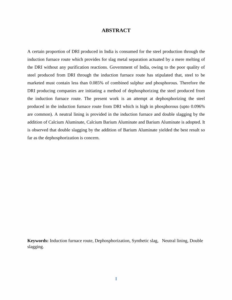
ABSTRACT
A certain proportion of DRI produced in India is consumed for the steel production through the
induction furnace route which provides for slag metal separation actuated by a mere melting of
the DRI without any purification reactions. Government of India, owing to the poor quality of
steel produced from DRI through the induction furnace route has stipulated that, steel to be
marketed must contain less than 0.085% of combined sulphur and phosphorous. Therefore the
DRI producing companies are initiating a method of dephosphorizing the steel produced from
the induction furnace route. The present work is an attempt at dephosphorizing the steel
produced in the induction furnace route from DRI which is high in phosphorous (upto 0.096%
are common). A neutral lining is provided in the induction furnace and double slagging by the
addition of Calcium Aluminate, Calcium Barium Aluminate and Barium Aluminate is adopted. It
is observed that double slagging by the addition of Barium Aluminate yielded the best result so
far as the dephosphorization is concern.
Keywords: Induction furnace route, Dephosphorization, Synthetic slag, Neutral lining, Double
slagging.

II
LIST OF TABLES
Chapter-2 Page No.
Table 2.1. Typical composition of iron ore……………………………………………………....20
Table 2.2. Typical composition of coal used for production if sponge iron……………………..20
Chapter-3
Table 3.1. Thermal characteristics of different synthetic slags…………………………….........25
Table 3.2. Details of the high temperature induction furnace……………………………………28
Chapter-4
Figure 4.1. Melting of mild steel rod in induction furnace………………………………………31
Table 4.2. Chemical composition of prepared synthetic slag……………………………………33
Table 4.3. Composition of slag produced after addition of Calcium Aluminate………………...36
Table 4.4. Composition of slag produced after addition of Calcium Barium Aluminate………..37
Table 4.5. Composition of slag produced after addition of Barium Aluminate…………………38
Table 4.6. Chemical composition of Metal samples……………………………………………..41
Chapter-5
Table 5.1. Chemical composition of slag, operating temperature and their Degree of
dephosphorization………………………………………………………………………………..45

III
LIST OF FIGURES
Chapter-2………………………………………………………………………………...Page No.
Figure 2.1. Relationship between decrease in elongation with increase in tensile strength……... 6
Figure 2.2. Effect of different elements on yield point of steel………………………………….. 7
Figure 2.3. Ellingham diagram…………………………………………………………………... 9
Figure 2.4. Dependence of distribution ratio, on the FeO content of slag……………………….10
Figure 2.5. Influence of Basicity on equilibrium Partion ratio…………………………………..11
Figure 2.6. Schematic of induction furnace……………………………………………………...12
Figure 2.7. Effect of frequency and bar diameter on efficiency of induction heating
of steel bar to 2000F. ……………………………………………………………………………14
Figure 2.8. Directions of current in induction coil and metal bath………………………………15
Figure 2.9. Electrodynamic circulation of metal in the induction furnace………………………16
Figure 2.10. Microstructure of sponge iron……………………………………………………...18
Figure 2.11. Rotary kiln terminology……………………………………………………………19
Chapter-3
Figure 3.1. Pictorial view of Leitz heating microscope………………………………………….25
Figure 3.2. Induction furnace used in the experiments…………………………………………..26
Chapter-4
Figure 4.1. Melting of mid steel rod in induction furnace……………………………………….31
Figure 4.2. Neutral refractory lining……………………………………………………………..32
Figure 4.3. Prepared synthetic slags……………………………………………………………..32
Figure 4.4. Line diagram of induction furnace…………………………………………………..33
Chapter-5
Figure 5.1. Phosphorous content of various samples…………………………………………….44

M. Tech. Thesis 2014
1 | P a g e
Chapter-1
M. Tech. Thesis 2014
2 | P a g e
1.1. Introduction:
Steel making in India is branched into two sections specifically primary route and secondary
route. In the primary route of steel making iron ore is used as raw material. In the first stage iron
ore is melted in a blast furnace to produce hot metal, and in second stage this hot metal is moved
to a steel making shop to produce steel in a basic oxygen furnace. In the secondary route of steel
making steel is produced using sponge iron, scrap etc. In this route steel is produced in electric
furnaces.
The main electric furnaces that are used in secondary steelmaking to produce steel are induction
furnace and electric arc furnace. As per the information presented by ministry of steel, total
manufacturing of crude steel in India is around 74MT in the last year. Out of this 35 percent steel
was produced using induction furnace. The prime raw material for induction furnace is steel
scrap, sponge iron and cast iron. The percentage of directly reduced iron in the burden differs
from 10 to 95 percent, depending on its inventory and monetary value of manufacturing. Large
scale of steel formed through secondary route is alloy steel and plain carbon steel. [2]
In the present work, our objective is to set up preliminary info for dephosphorization of steel in
150 kg induction furnace. As for the expulsion of phosphorous basic environment is desirable,
the basicity is controlled by the addition of Barium Aluminate, Calcium Aluminate and Calcium
Barium Aluminate in the form of slag. The FeO present in DRI is responsible for providing
oxidation potential to the added slag. Three heats had been carried out for each slag and, slag and
metal samples were collected to determine the degree of dephosphorization.
Phosphorous comes to induction furnace from DRI and pig iron and the quality of pig iron
depends on the quality of hematite. The range of phosphorous varies from 0.05 to 0.09 % with
the variation in the quality of raw materials. Steel containing phosphorous has some adverse
effect on the quality of steel, hence the amount of phosphorous should be beneath a suitable
amount. The elimination of phosphorous from steel is conducted by oxidation. The compound
which is produced after oxidation reaction is in the form of P₂O₅, which is a component of the
dross. Dephosphorization is very much sensitive towards the operating temperature of the
furnace. Because at very high temperature phosphorous in the dross may get back to the steel.
M. Tech. Thesis 2014
3 | P a g e
On the primary route of steel making oxidation potential for removal of phosphorous is obtained
by direct lancing of the oxygen jet into the bath. But in induction furnace route it is difficult to
remove phosphorous by oxygen lancing because, here the height of metal level is equal to the
depth of furnace. The second constraint that suppresses dephosphorization is the acidic refractory
lining which is used in induction furnaces. The removal of phosphorous and sulfur is difficult
with acidic lining as they form basic slag. In the present work we had used Magnesia based basic
lining for the removal of phosphorous. [13, 14]
1.2. Purpose of the project:
a) Dephosphorization of steel.
b) Optimization of raw material chemistry.
c) To increase the yield of the process
Objective 1 ………… High productivity with better quality
Action plan ………… Induction furnace making quality steel by Dephosphorization
Objective 2 ………… To improve yield.
Action plan................. Reduce slag FeO% with carbon.

M. Tech. Thesis 2014
4 | P a g e
Chapter-2
M. Tech. Thesis 2014
5 | P a g e
2.1. Introduction:
The estimate for the development of induction furnace starts, when the principle of
electromagnetic induction was discovered by Michael Faraday. Then first experiment on
induction furnace was started by De Ferrant in 1870. In 1890 the first induction furnace was
patented by Edward Allen for melting metal. [6]
There are two basic laws of electricity:
a) The first is that a current flowing through a conductor will bring forth a magnetic field
around that conductor. If this wire is wound into a cylindrical coil, the magnetic field of
each turn is added producing an intensified magnetic field. The field is related to the
amount and direction of the current. The field is maximum when the current is maximum
and will reverse direction if the current reverses direction.
b) The second fundamental is related to Faraday's Law, which says that when a flux which
links a coil is changing, there is an electro-motive force (emf) induced in the coil. If these
flux linkages change in a closed electric circuit, the emf produced causes a current to
flow. A solid metallic block will produce currents swirling around in eddies in a plane
perpendicular to the flux. These eddy currents produce the I2R losses which generate the
heat required. Proper selection of coil frequency and power density allows for the
practical application of induction heating and melting.
2.2. Effect of phosphorus on the properties of steels:
Steel containing phosphorous has some adverse as well as good effects. Phosphorous has great
influence towards the solid solution strengthening of ferrite. The comportment of a modest
quantity of phosphorous can increase the yield and ultimate strength of mild steel. It also
increases the deep drawability and hardness of steel. Referable to the above advantages such
steels are used for cold forming operation. Phosphorous in steel can also increase corrosion
resistance and metal cutting characteristic. [4]
M. Tech. Thesis 2014
6 | P a g e
On the other hand the harmful effects of phosphorous in steel include various types of
embrittlement, which reduce the resilience and malleability. High phosphorous steel melt has
low melting point film, which produces crack during continuous casting.
2.2.1. Cold shortness in steel:
The brittle behavior of steel containing phosphorous, at a temperature less than recrystallization
temperature is called cold shortness. It is a condition of wrought iron, steel, or other metal, in
which the metal, on account of its brittleness, cannot be worked when cold without fracture or
cracking at the edges. Phosphorous decreases ductility and hence increase the tendency of the
steel to produce crack during cold working.
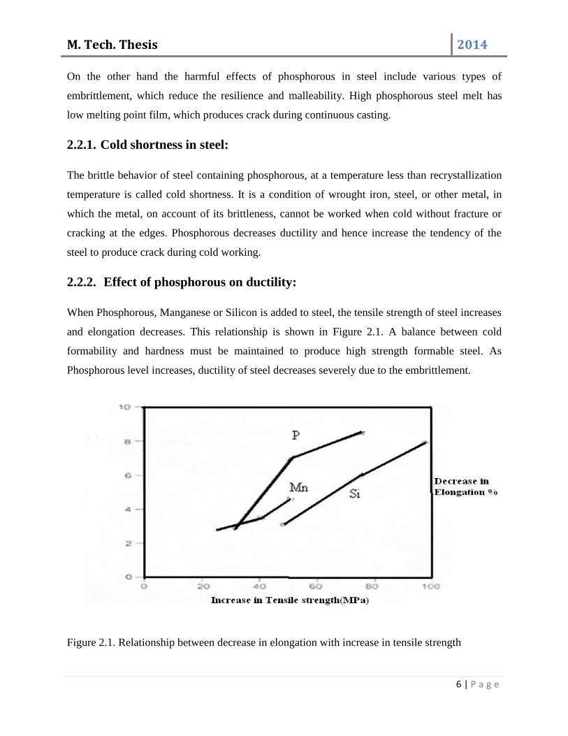
2.2.2. Effect of phosphorous on ductility:
When Phosphorous, Manganese or Silicon is added to steel, the tensile strength of steel increases
and elongation decreases. This relationship is shown in Figure 2.1. A balance between cold
formability and hardness must be maintained to produce high strength formable steel. As
Phosphorous level increases, ductility of steel decreases severely due to the embrittlement.
Figure 2.1. Relationship between decrease in elongation with increase in tensile strength

M. Tech. Thesis 2014
7 | P a g e
2.2.3. Effect of phosphorous on strength:
Figure 2.2 show the change in lower yield point as a function of alloy addition. From the Figure
2.2 we can conclude that, small amount of phosphorous can increase yield point by a large
amount. Only Carbon and Nitrogen have a higher strengthening effect than phosphorous. This is
because, phosphorous is substitutional solute in ferrite, where as Carbon and Nitrogen enter the
crystal lattice as an interstitial solute.
Figure 2.2. Effect of different elements on yield point of steel.
2.3. Sources of phosphorous input:
Phosphorous comes in to steelmaking furnace from:
• Hot Metal
All the phosphorous present in blast furnace burden goes to hot metal, since
deohosphorization is not possible in blast furnace due to reducing atmosphere.
• Sponge iron
Sponge iron may contain upto 1.0% phosphorous.
• Recycled BOF Slag
• Coke
M. Tech. Thesis 2014
8 | P a g e
2.4. Requirement of Low phosphorus Steels:
• To have improved mechanical properties like temper embrittlement, low temperature ductility
etc.
• To have better corrosion resistance and deep drawing properties
• To reduce hydrogen induced cracking and stress corrosion cracking
• To reduce chances of cracking during bending
• For the equipment in chemical industry
• For reprocessing equipment of the nuclear industry
• To prevent segregation during continuous casting.
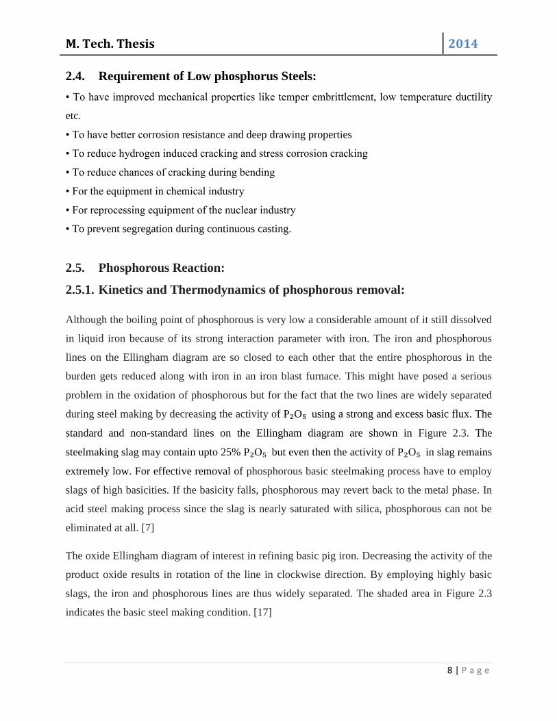
2.5. Phosphorous Reaction:
2.5.1. Kinetics and Thermodynamics of phosphorous removal:
Although the boiling point of phosphorous is very low a considerable amount of it still dissolved
in liquid iron because of its strong interaction parameter with iron. The iron and phosphorous
lines on the Ellingham diagram are so closed to each other that the entire phosphorous in the
burden gets reduced along with iron in an iron blast furnace. This might have posed a serious
problem in the oxidation of phosphorous but for the fact that the two lines are widely separated
during steel making by decreasing the activity of P₂O₅ using a strong and excess basic flux. The
standard and non-standard lines on the Ellingham diagram are shown in Figure 2.3. The
steelmaking slag may contain upto 25% P₂O₅ but even then the activity of P₂O₅ in slag remains
extremely low. For effective removal of phosphorous basic steelmaking process have to employ
slags of high basicities. If the basicity falls, phosphorous may revert back to the metal phase. In
acid steel making process since the slag is nearly saturated with silica, phosphorous can not be
eliminated at all. [7]
The oxide Ellingham diagram of interest in refining basic pig iron. Decreasing the activity of the
product oxide results in rotation of the line in clockwise direction. By employing highly basic
slags, the iron and phosphorous lines are thus widely separated. The shaded area in Figure 2.3
indicates the basic steel making condition. [17]
M. Tech. Thesis 2014
9 | P a g e
Figure 2.3. Ellingham diagram.
The partitioning of phosphorous between slag and metal can be given as:
2[P] + 5(FeO) + 3(CaO) = (3CaO. P₂O₅) + 5[Fe]
And the equilibrium constant is:
K = ( ) , -
, - ( ) ( )
The ratio of phosphorous content in slag to that in metal is generally referred to as phosphorous
partition coefficient Dp which has a higher value for higher basicity and higher oxidizing power
of the slag.
The activity function for phosphorous distribution between slag and metal as obtained by Flood
is:
Log K = 21N´ (Ca² ) + 18N´(Mg² ) + 13N´(Mn² ) + 12N´(Fe² ) + …

M. Tech. Thesis 2014
10 | P a g e
That is the dephosphorizing ability of various basic oxide is in the ratio of,
Ca : Mg : Mn : Fe
1021
: 1018
: 1013
: 1012
30,000 : 1000 : 3 : 1
In other words lime is 30 times more effective on molar basis and 20 times more effective on
weight basis for dephosphorization than magnesia. The FeO is only effective as an oxidizing
agent and not as a base. Of course, Na₂O, BaO are in the more powerful than CaO, but they
cannot be used in steel making owing to their tendency to attack the lining of the furnace. The
inter-relationship of partition coefficient, basicity and FeO content found in laboratory
experiments are shown in Figure 2.4 and Figure 2.5. The partition coefficient increases with
increase FeO content upto 15% because of its high oxidizing ability. If FeO content increase
beyond a certain limit, the ratio of lime is decreased and hence the advantage of high oxidizing
ability of FeO is neutralized by the loss of time in the slag resulting in a maximum partition
coefficient at around 15% FeO. Increase in temperature tends to lower the value of partition
coefficient and vice-versa and hence dephosphorization is more effective at low temperature.
Figure 2.4. Dependence of distribution ratio, on the FeO content of slag
M. Tech. Thesis 2014
11 | P a g e
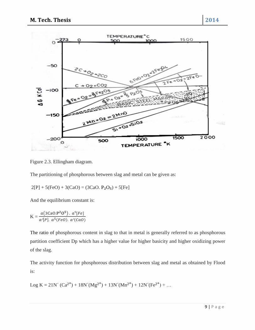
Figure 2.5. Influence of Basicity on equilibrium Partition ratio.
Soda ash is 100 times superior to lime, on molar basis, for dephosphorization, but its use in
practice is forbidden because of its severe corrosive action on furnace refractories. Usually the
magnesia content of basic steel making slag is not under control because it reaches equilibrium
with furnace lining. The steelmaking is, therefore, left with the control on lime, silica and iron
oxide content of the slag to effect required dephosphorization of the melt.
Since phosphorous oxidation is highly exothermic reaction it is favored by lower temperature.
Excessively high temperature, risen in the course of refining, may lead to reversion of
phosphorous from slag to metal during steel making in actual practice. [7]
2.6. Need for low phosphorous steels:
• Causes hot shortness and temper embrittlement.
• Ductility and strength goes down if phosphorous is very high.
• Essential when want to have excellent mechanical properties (Ductility, Toughness and
Strength).
• For special applications (Automobiles EDD Applications [P] < 0.010).
• Increasing proportion of continuous cast heats where high temperature at end point is not
favorable for dephosphorisation.
• High phosphorous heats cause more breakouts in continuous casting due to formation of low
melting point film.
M. Tech. Thesis 2014
12 | P a g e
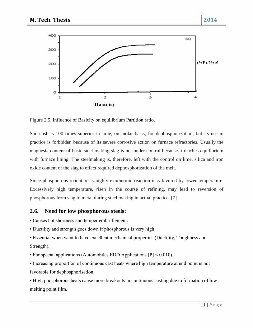
2.7. Induction furnace steelmaking:
A melting furnace in which electric current is applied to melt metal is called induction furnace.
Melting and alloying a wide variety of metals with minimum melt loss are the features of
induction furnace. Induction furnace is also used for refining of metal. [6]
Straight off a day’s induction furnace making has come forth as a major steel producing
operation. In India induction furnace plants are termed as mini steel plants, because the
maximum production capacity of these plants is less than 1MT of steel per year. In induction
furnace, steel scrap is used as charge material, only due to less availability of steel scrap directly
reduced iron (DRI) is likewise utilized in induction furnace. Now a days induction furnace in
integrated with mini blast furnace, and in such type of plants the metallic charge, usually consists
of hot metal, steel scrap and DRI in varying proportions to get different properties of steel.
Improvement of induction furnace design goes on day by day, which permits enhancement of
electrical efficiency in modern furnaces, and metallurgical efficiency has also been greatly
improved by oxygen lancing.
Figure 2.6. Schematic of induction furnace

M. Tech. Thesis 2014
13 | P a g e
2.8. Types of induction furnace:
There are basically two designs of induction furnaces are available, namely, the core type or
channel furnace and the coreless type. Both types have advantages which make one or the other
suitable to a particular operation. As compared to coreless induction furnace, core type furnace is
a more efficient type of induction furnace. In case of core type construction maximum power
transfer into the metal is possible. This design has a distinct advantage of providing a large
capacity of molten metal with low holding power level. Core type induction furnace is an
excellent furnace for small foundries with special requirements for large castings. Because of the
requirement to keep the channel molten, core type furnaces are energized 24 hours a day. Hence
the application of core type furnace is limited to one alloy or similar base alloy. Hence the power
supplies are of line frequencies of 60 or 50 Hz. If quick melting of one alloy is desirable, then
coreless induction furnace is used. The coreless furnace can be used for one shift operation
because it is easy to stop and restart the furnace. [6]
Coreless induction furnace process has some advantages over other types of arc furnace.
i. Since there are no electrodes, it is possible to melt steels very low in carbon.
ii. The metal produced is really low in gases because of the absence of arc.
iii. Temperature control of the process can be managed easily.
The disadvantages of induction furnace are:
i. Life of basic lining is low.
ii. Low temperature of slag, which is heated from the metal.
2.9. Devices for Electric heating:
Any material through which an electric current flows is heated thereby. The rate at which heat is
generated depends on current density and the specific resistance of the material which is called
as a ‘resistor’. [11]
Electric energy can be utilized for industrial heating in several ways.
a) The material to be heated serves as a resistor.

M. Tech. Thesis 2014
14 | P a g e
b) Separate resistors transfer heat to the work load by radiation and convection and in a few
cases by conduction.
c) The work load is heated by induced current.
2.10. Principle of induction furnace:
The principle of induction furnace is the induction heating.
2.10.1. Induction Heating:
A change in the electric current that flows in a wire causes a change in the magnetic conditions
around the wire. The change in magnetism can be used to produce an electric current in a
properly placed object, which is heated by the current. The general equipment required for
induction heating consists of a coil of wire in which alternating current flows. The object to be
heated is placed inside the coil of wire. Factor affecting distribution of temperature in the heated
object is the frequency of alternation (cycles per second).
At a high frequency, temperature at the skin of the work piece is highest. The rate of heating
decreases exponentially and rapidly towards the center. At low frequency also distribution of
temperature from skin to the center is exponential, but temperature decreases more gradually
than it drops with high frequency. This is the facts; bars of large cross section are heated with
low frequency. [11]
Figure 2.7. Effect of frequency and bar diameter on efficiency of induction heating of steel bar to
2000F.

M. Tech. Thesis 2014
15 | P a g e
Induction coils are not expensive, but additional equipment required for induction heating is
expensive. Low frequency (60cps) heating requires more capacitors for correction of the power
factor.
2.11. Construction and Working:
There are two types of furnaces namely combustion furnace and induction furnace. They produce
heat in two different manners. The furnace in which heat is produced by burning a fuel like
natural gas, coal, etc. is called combustion furnaces (heat required for melting of the charge
material is obtained by burning of the fuel). But in induction furnaces, heat generated is not by
combustion.
Alternating current from a power supply flows into a furnace and through a coil which is built up
of hollow copper tubing. Due to this an electromagnetic field is created which passes through the
refractory lining and couples with conductive metal charge inside the furnace. Then an electric
current flows inside the metal charge, generating heat, which causes metal to melt. [15]
Figure 2.8. Directions of current in induction coil and metal bath.
2.12. Electrodynamics phenomena in coreless induction furnace:
In a coreless induction furnaces there are two concentric conductors. The inductor works as
external conductor and the molten metal, the internal one. In these conductors current flows in
the opposite direction, and they repel each other. As the inductor is a rigid conductor, it remains

M. Tech. Thesis 2014
16 | P a g e
fixed, while the molten metal moves from the wall of the furnace towards the axis of the
crucible.
The magnetic flux extends horizontally over the metal surface, after it passes from the annular
gap between the two conductors. The horizontal component of the magnetic field produces
electrodynamic forces which act perpendicular to the surface of the metal that is upwards at the
bottom and downwards at the top surface of the metal. Force is maximum at the wall of the
furnace.
This combined effect of horizontal and vertical forces causes the metal to circulate and forms a
convex metal surface. An advantage of this phenomenon is that the metal is stirred, which
equalizes its temperature and composition and speeds up melting, but the convex portion of the
metal is thus exposed, since the slag flows towards the walls. It is possible to cover the meniscus
by increasing the bulk of slag, but this may have an adverse effect on the lining.
Figure 2.9. Electrodynamic circulation of metal in the induction furnace:
2.13. Advantages of induction furnace over electric arc furnace:
Induction furnace consumes less power compared to EAF due to faster melting, lower taping
temperature and higher power density. Melting of FeCr is difficult in an arc furnace due to the
M. Tech. Thesis 2014
17 | P a g e
absence of stirring. Also, heat losses in EAF are high as lime and fluxes added to protect the
lining take away substantial amount of heat.
In induction furnace no electrodes are used as in EAF thus reducing cost of production. Again it
uses lesser quantity of refractory. Initial investment of plant and equipment is less. Acidic
ramming mass used in induction furnace is much cheaper when compared to basic ramming
mass and bricks used in EAF.
Induction furnace has lower tapping temperature compared to EAF to recover the oxidized
chromium. Also there is no need to add reductants like carbon or FeSi in induction melting
unlike in the EAF. Recovery of chromium is higher in induction furnace compared to EAF as
negligible amount of chromium is oxidized in induction furnace. [5]
2.14. Manufacturing of DRI
2.14.1. Introduction
Direct reduction, an alternative route of iron making, overcomes some of the conventional blast
furnace. Direct reduced iron (DRI) which is also known as sponge iron is manufactured through
either natural gas or coal based technology. Oxygen from the iron ore escapes during the solid
state reduction and leaves pores. When observed under the microscope, this looks similar to
sponge, hence the name sponge iron.
Iron ore is reduced in solid state at 700°C to 1050°C either by reducing gas (H+CO) or coal. The
investment and operating costs of direct reduction plant are low compared to blast furnace which
requires coking coal for producing coke. Demand for use of DRI in steel making is increasing
due to shortage of steel scrap and power.
The principal constituents of sponge iron are metallic iron, residual iron oxides, carbon and
impurities such as phosphorous, Sulphur, Silica, Aluminum etc.
Micro structure of sponge iron looks as follows:
M. Tech. Thesis 2014
18 | P a g e
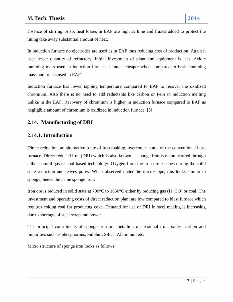
Fe2O3
Fe3O4
Wustite
Metallic iron
Figure 2.10: Microstructure of sponge iron
2.14.2. Characteristics of DRI
DRI can be produced in different forms, namely pellet, lump and hot briquette. The secondary
product form from fine DRI is called cold briquetted iron. Hot briquette is also known as hot
briquetted iron (HBI). Hot briquetted iron is a mixed solid form of pellet and lump which is
pressed as 800 to 7000C immediately after reduction. Quality of hot briquetted iron can be varied
by mixing lumps and pellets in different ratios. Due to high density and low surface area of hot
briquetted iron, there is a low chance of.
Oxygen present in the DRI is in the form of FeO, which reacts eagerly with carbon in the molten
bath and improves heat transfer, slag metal contact and homogeneity of the bath. DRI having
higher Carbon content is desirable. Hence, gas based DRI (which content 1.0 to 2.5% C) is more
desirable than coal based DRI (0.2% C). Depending on the process used for DRI production, the
degree of metallization varies from 80 to 95%. Low degree of metallization leads to higher dross
volume, more power consumption, increased heat time and low yield during steel making. [3, 16]
2.14.3. Types of sponge iron making:
A. Coal based processes using rotary kiln.
B. Coal based processes using shaft furnace.

M. Tech. Thesis 2014
19 | P a g e
C. Retort processes using gas or coal as the reluctant.
Rotary kiln:
Rotary kiln is reactor for sponge iron making, but it is also used for calcinations of lime stone,
production of cement and manufacturing of refractory material. Because of its versatile usage in
processing materials, it is used for drying, heating, calcining, sintering and reduction.
Normally the coal based rotary kiln method of making sponge iron is followed by the plants.
Rotary kiln is like a closed vessel. The vessel body is container of uniform cylindrical shape. Its
charging end is open for discharging gas and feeding raw materials. The other end is used for
discharging of product and gangue material. The vessel body (shell) is made of boiler quality
steel. The shell is protected by an inside layer of high alumina refractory, which takes care of the
high operating temperature of 1000-1100°C. The kiln rotates at a constant speed with the help of
gears and motors arrangement supported by rollers. Each kiln has seven zones, and each zone
having blowers for supplying atmospheric air inside the kiln for burning of coal. Thermocouples
are arranged in different zones to measure the operation temperature. [5]
Figure 2.11: Rotary kiln terminology.
M. Tech. Thesis 2014
20 | P a g e
Table 2.1: Typical composition of iron ore.
Elements Percentage (%)
Fe (Total) 62
SiO2 3.5
Sulphur 0.01
Al2O3 4
Phosphorous 0.04
Loss of ignition 5
Tumbler index 85
Table 2.2: Typical composition of coal used for production if sponge iron.
Elements Percentage (%)
Ash 32-35
Volatile matter 30-35
Fixed carbon 35-42
Sulphur 0.6
Phosphorous 0.1 maximum
Moisture 10-15 maximum
Particle size 10-15mm maximum
Limestone and dolomite are used as flux for de-sulphurization in sponge iron making process,
since removal of Sulphur in steel making is more expensive than sponge iron process.
M. Tech. Thesis 2014
21 | P a g e
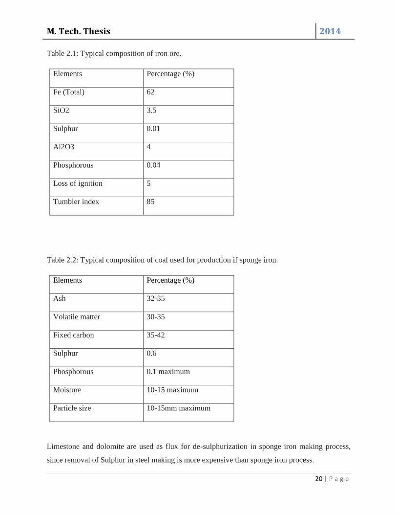
2.14.4. Process flow chat for sponge iron production:
2.15. Major factors affecting dephosphorisation:
The best conditions for phosphorous removal from liquid steel from a thermodynamic viewpoint
can be summarized as: [8, 9]
A high basic, lime rich slag.
A satisfactory high level of oxidation of iron (FeO content).
The lowest possible temperature.
The lowest possible amount of undissolved free lime in slag.
An increased metal slag interface.
Droplet generation trajectory and residence time
Blowing Regime (Lance Height vs. Flow rate)
2.16. Limitations of dephosphorization:
Poor yield of steel due to reblows; iron loss,
Loss in the lining life of the converter ,
Loss due to poor recovery of ferroalloys,
Reduced life of ladles,
Raw material charging into
ground hooper Cusher house Screen house
Stock house day bin
raw material charging in kiln
Cooling through cooler
Product conformation
Sponge iron separation
Dispatch
M. Tech. Thesis 2014
22 | P a g e
Diversion of grades due to uncertain oxygen content of steel.
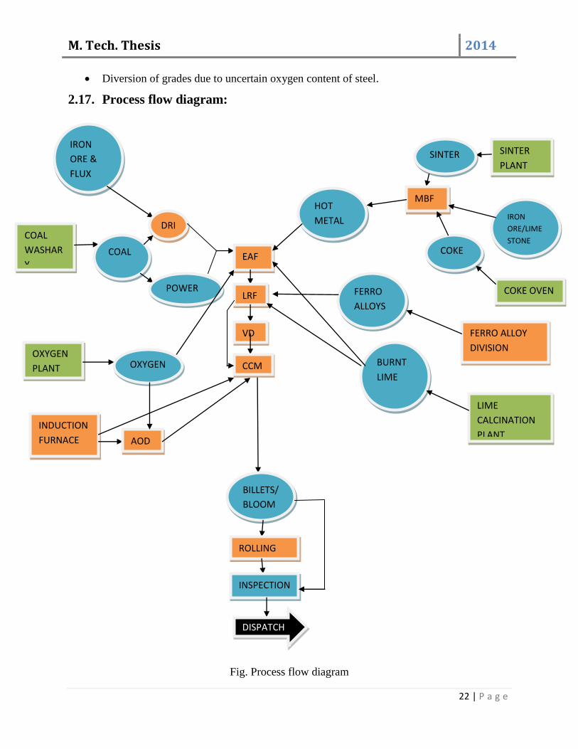
2.17. Process flow diagram:
Fig. Process flow diagram
IRON
ORE &
FLUX
DRI COAL
WASHAR
Y COAL
POWER
EAF
LRF
VD
CCM OXYGEN
PLANT OXYGEN
INDUCTION
FURNACE AOD
BILLETS/
BLOOM
S
ROLLING
INSPECTION
DISPATCH
SINTER
PLANT SINTER
MBF
IRON
ORE/LIME
STONE COKE
COKE OVEN
FERRO ALLOY
DIVISION
FERRO
ALLOYS
BURNT
LIME
LIME
CALCINATION
PLANT
HOT
METAL

M. Tech. Thesis 2014
23 | P a g e
Chapter-3
M. Tech. Thesis 2014
24 | P a g e
3.1. High Temperature Microscope:
3.1.1. Theory:
The heating microscope helps in determining characteristics of a sample, as prescribed in general
industrial standard 51730.
The flow characteristic presented in terms of the characteristic temperature.
IDI: Initial deformation temperature
ST: Softening temperature
HT: Hemispherical temperature
FT: Flow temperature
Initial deformation temperature:
At this temperature rounding of edge of the curve occurs. The initial shape change indicates the
beginning of sintering. The temperature helps us to determine surface thickness and thickness of
the sample.
Softening temperature:
At this temperature outline of the sample changes. This is reported by the temperature at which
specimen sinks by 1division after IDT. It symbolizes the start of plastic deformation.
Hemispherical temperature:
At this temperature same is fused to a hemispherical shape. This is the melting point, according
to German standards. It symbolizes sluggish flow of sample material.
Flow temperature:
At this temperature the sample liquefies, measured at 1/3 of height as measured at HT. It
symbolizes liquid mobility of sample.
M. Tech. Thesis 2014
25 | P a g e
3.1.2. Procedure:
The sample was put on this furnace and heated initial temperature bung the room temperature.
Flow characteristics as presented in terms of four characteristics are observed.
Temperature at which first rounding of edge occurred, was noted as IDT. The temperature at
which outline of specimen changed and if sink by 1 division after IDT was noted as ST. The
temperature, at which the height of specimen was observed to be one third of its height at HT,
was noted as FT.
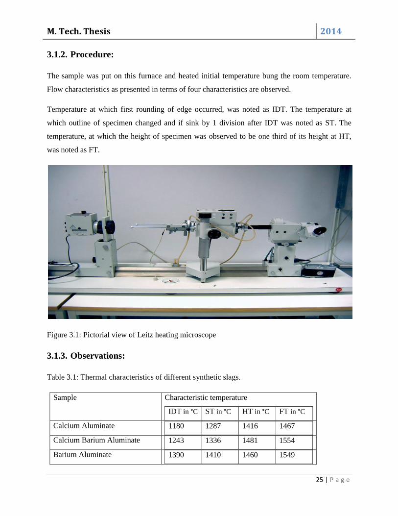
Figure 3.1: Pictorial view of Leitz heating microscope
3.1.3. Observations:
Table 3.1: Thermal characteristics of different synthetic slags.
Sample Characteristic temperature
IDT in °C ST in °C HT in °C FT in °C
Calcium Aluminate 1180 1287 1416 1467
Calcium Barium Aluminate 1243 1336 1481 1554
Barium Aluminate 1390 1410 1460 1549
M. Tech. Thesis 2014
26 | P a g e
3.1.4. Discussion:
At ST, the height of the specimen decreased by 1division from IDT.
At HT, the height is the half of the base.
At FT, the height was one third of the height at FT.
The time taken by a sample to reach FT stage depends on sample that is, it varies from
sample to sample.
High temperature microscopy required for improving heat furnace operation by the analysis, the
temperature of surface stickiness of sample, that of plastic deformation flow of sample and liquid
mobility can be obtained, on the basis of this, for a particular quality of material, various zones
blast furnace or granular zone, cohesive zone, core active zone, stagnant zone and hearth can be
adjusted.
3.2. Induction furnace:
Experiments for dephosphorization of steel in induction furnace were carried out in 150 Kg
coreless type induction furnace of electrotherm Ltd. in Dalmia institute of scientific and
industrial research (DISIR), Rajgangpur. The volume of the furnace was brought down to 40 Kg
for easy manipulation. Alumina bricks with dry Al2O3 ramming mass were used as a lining.
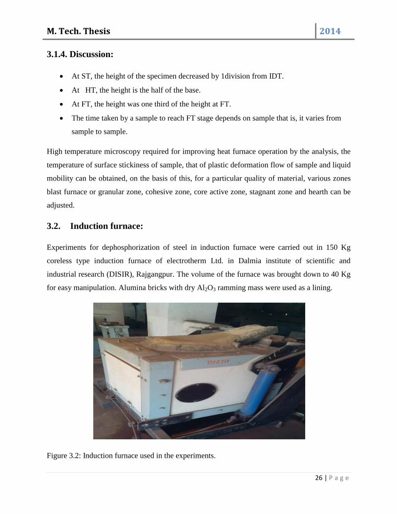
Figure 3.2: Induction furnace used in the experiments.
M. Tech. Thesis 2014
27 | P a g e
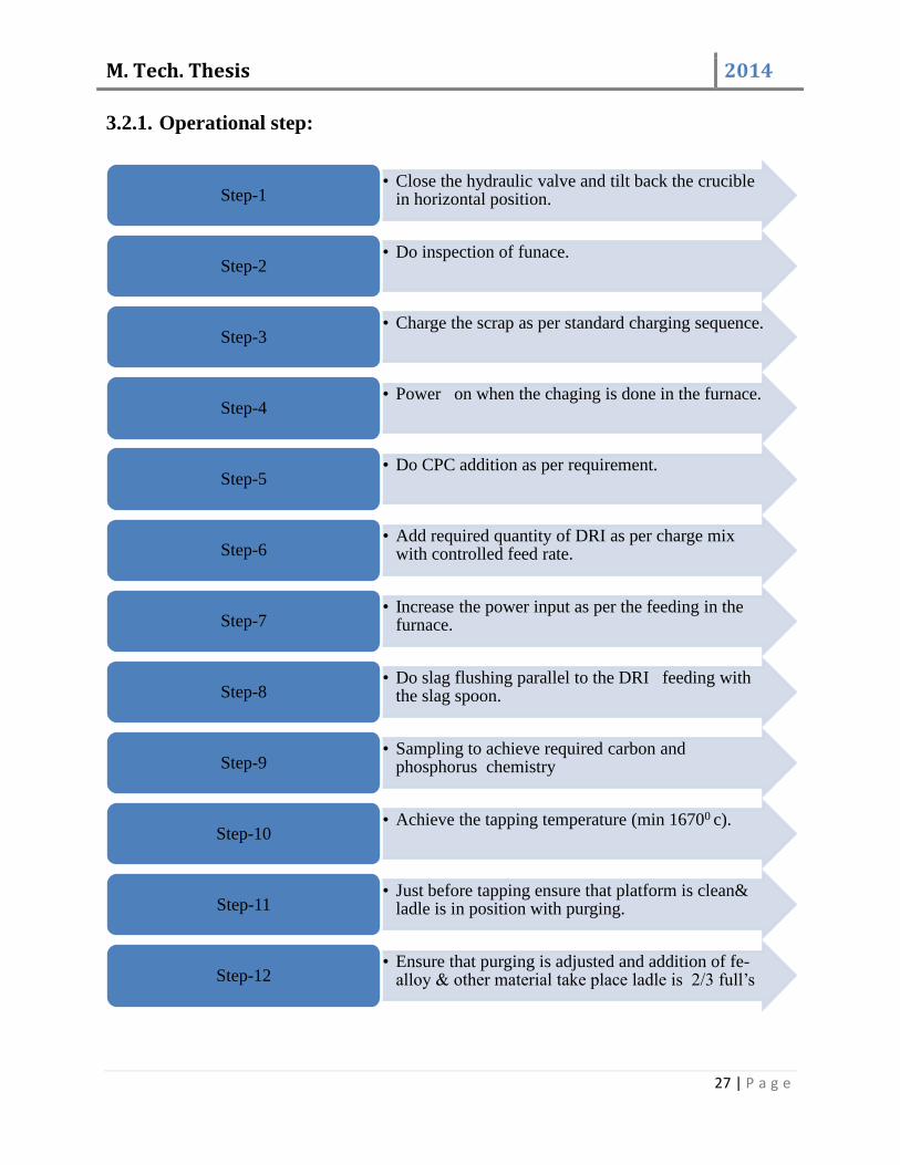
3.2.1. Operational step:
• Close the hydraulic valve and tilt back the crucible in horizontal position. Step-1
• Do inspection of funace. Step-2
• Charge the scrap as per standard charging sequence. Step-3
• Power on when the chaging is done in the furnace. Step-4
• Do CPC addition as per requirement. Step-5
• Add required quantity of DRI as per charge mix with controlled feed rate. Step-6
• Increase the power input as per the feeding in the furnace. Step-7
• Do slag flushing parallel to the DRI feeding with the slag spoon. Step-8
• Sampling to achieve required carbon and phosphorus chemistry Step-9
• Achieve the tapping temperature (min 16700 c). Step-10
• Just before tapping ensure that platform is clean& ladle is in position with purging. Step-11
• Ensure that purging is adjusted and addition of fe-alloy & other material take place ladle is 2/3 full’s Step-12
M. Tech. Thesis 2014
28 | P a g e
Table 3.2. Details of the high temperature induction furnace.
Maximum working temperature 1800°C
Diameter of furnace tube 20cm internal diameter
Depth of furnace tube 30cm
End cooling Copper spiral for water circulation
Type of thermocouple Pt-Rh type
Volume of furnace 9000cm
Frequency 1000Hz
Power 150KW

M. Tech. Thesis 2014
29 | P a g e
Chapter-4
M. Tech. Thesis 2014
30 | P a g e
4.1. Experimental set up:
Laboratory scale experiments for dephosphorization of steel in induction furnace were carried
out in 150 Kg coreless type induction furnace of electrotherm Ltd. in Dalmia institute of
scientific and industrial research (DISIR), Rajgangpur. The volume of the furnace was brought
down to 40 Kg for easy manipulation. Usually acidic lining is used in induction furnace but, here
we had used neutral lining. Platinum Rhodium thermocouple was used to measure the operating
temperature of the furnace. The raw materials used were mild steel rods (steel scrap) and sponge
iron. The ratio of raw material was a 85% sponge iron and 15% steel scrap. The chemical
composition of charge mix is given in table 4.1.
The furnace was dried after putting a mild steel rod and run the furnace at 10KW power for
1hour. Then 5kg mild steel was taken and melted at a power of 50KW. Initially the furnace was
started with 10KW power supply and in each 10 min power was raised by 10KW up to 50KW.
The frequency of the furnace was maintained in between 900 to 950 Hz. After complete melting
40kg sponge iron was added slowly. Total time taken for addition was 1hour. After complete
addition of sponge iron temperature was measured. Then total slag was removed by spatula and
temperature was measured 1630°C. Metal sample (metal sample 1) and slag sample (slag sample
2) was collected. Slag sample was taken out with the help of a spatula and metal sample was
collected by tilting the furnace. Then 1500gm of Calcium Aluminate (mayanite) was added. The
composition of Calcium Aluminate was 75% CaO and 25% Al2O3. Along with Calcium
Aluminate 300gm of mill scale was also added in to the furnace. At this condition power was
reduced to 35KW. Then again temperature was measured and it was around 1602°C. Total slag
was removed and slag sample (slag sample 2) was collected. Metal had been removed and metal
sample (metal sample 2) had been collected. Total metal had been removed from the furnace.
Same experimental procedure had been followed for next two experiments where Calcium
Barium Aluminate and Barium Aluminate were added as synthetic slag. The slag and metal
samples for second and third heat were collected at 1607°C and 1610°C respectively

M. Tech. Thesis 2014
31 | P a g e
Figure 4.1. Melting of mid steel rod in induction furnace.
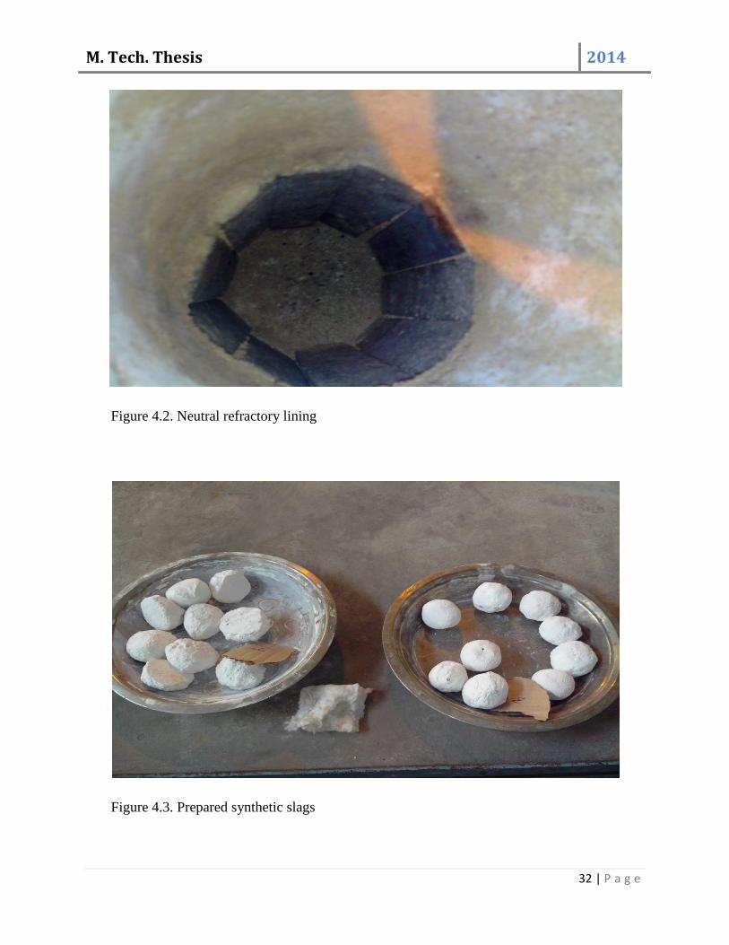
The sponge iron used in the experiments was provided by Odisha iron and steel Ltd (OISL),
Rajgangpur. Chemical composition of sponge iron was determined by chemical analysis in
OISL. Steel scrap analysis was done by spectrometer analysis. Before conducting the experiment
three different slags were prepared namely Calcium Aluminate, Calcium Barium Aluminate and
Barium Aluminate.
Table 4.1. Chemical composition of raw materials
DRI % STEEL SCRAP %
Fe-M……………78-80 C……..…………....…0.22
Fe-T….…………87-90 S…………..…………0.045
P…………..........0.096 P………………..........0.075
S ……...………..0.03 Si………….................0.27
C.……….…........0.1 Mn…………………...0.50
SiO₂……………2.404
M. Tech. Thesis 2014
32 | P a g e
Figure 4.2. Neutral refractory lining
Figure 4.3. Prepared synthetic slags

M. Tech. Thesis 2014
33 | P a g e
Table 4.2. Chemical composition of prepared synthetic slag
NAME OF SLAG CHEMICAL COMPOSITION
Calcium Aluminate CaO – 75%, Al₂O₃ - 25%
Calcium Barium Aluminate CaO – 35%, Al₂O₃ - 25%, BaO – 40%
Barium Aluminate BaO – 75%, Al₂O₃ - 25%
Figure 4.4. Line diagram of induction furnace.
Line diagram of coreless induction furnace used in the experiments is given in Figure 4.4. It
shows the various dimensions along with different parts of induction furnace.
4.2. Basis of calculation:
4.2.1. Rate of melting:
a) On the basis of initial weight:
DRI dissolve in molten bath,
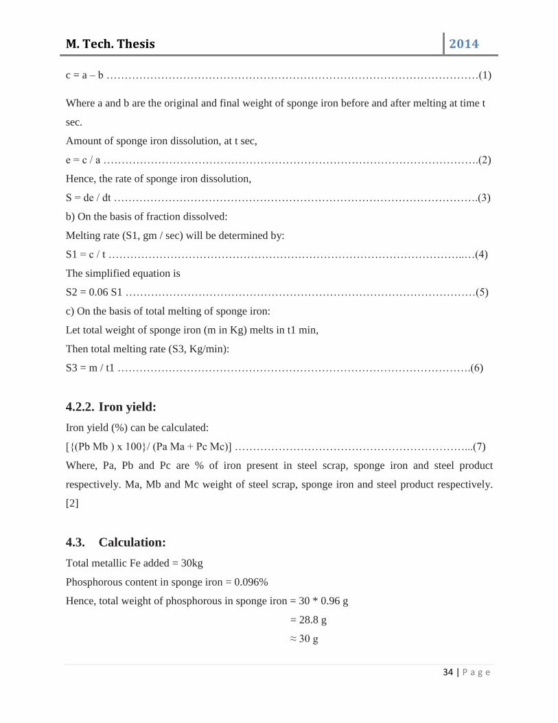
M. Tech. Thesis 2014
34 | P a g e
c = a – b …………………………………………………………………………………………(1)
Where a and b are the original and final weight of sponge iron before and after melting at time t
sec.
Amount of sponge iron dissolution, at t sec,
e = c / a ………………………………………………………………………………………….(2)
Hence, the rate of sponge iron dissolution,
S = de / dt ……………………………………………………………………………………….(3)
b) On the basis of fraction dissolved:
Melting rate (S1, gm / sec) will be determined by:
S1 = c / t ……………………………………………………………………………………..…(4)
The simplified equation is
S2 = 0.06 S1 ……………………………………………………………………………………(5)
c) On the basis of total melting of sponge iron:
Let total weight of sponge iron (m in Kg) melts in t1 min,
Then total melting rate (S3, Kg/min):
S3 = m / t1 …………………………………………………………………………………….(6)
4.2.2. Iron yield:
Iron yield (%) can be calculated:
[{(Pb Mb ) x 100}/ (Pa Ma + Pc Mc)] ………………………………………………………...(7)
Where, Pa, Pb and Pc are % of iron present in steel scrap, sponge iron and steel product
respectively. Ma, Mb and Mc weight of steel scrap, sponge iron and steel product respectively.
[2]
4.3. Calculation:
Total metallic Fe added = 30kg
Phosphorous content in sponge iron = 0.096%
Hence, total weight of phosphorous in sponge iron = 30 * 0.96 g
= 28.8 g
≈ 30 g

M. Tech. Thesis 2014
35 | P a g e
Let metallization of sponge iron = 80%
And Fe (Total) = 92%
So, Fe (Metallic) = (80*92) / 100
= 73.6
To get 30kg Fe (Metallic), amount of sponge iron required = 30 / 0.736
≈ 40kg
Molecular weight of phosphorous = 31
Molecular weight of O = 16
Molecular weight of P₂O₅ = 142
Molecular weight of 4CaO = 224
To remove 62gm of phosphorous, required amount of P₂O₅ = 142gm
To remove 1gm of phosphorous, required amount of P₂O₅ = (142/30) g
To remove 30gm of phosphorous, required amount of P₂O₅ = (142/30)*30g
= 68.71 g
P₂O₅ is present in the slag in the form of 4CaOP₂O₅.
For 142gm of P₂O₅ we require 224g of CaO
Hence, for 68.71gm of P₂O₅ we require (224 / 142) * 68.71 g of CaO
= 108.39g of CaO
Thus, with 30kg metallic iron, 108.39gm CaO was added.
For 30kg metal 5% synthetic slag was added, that is 1500 g synthetic slag.
Along with 1500 g synthetic slag 20% mill scale was added. (i.e. 300 g).
4.4. Experiment:
4.4.1. Heat-1:
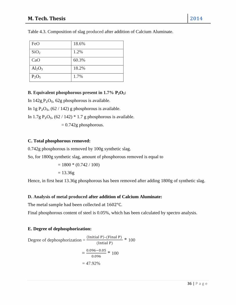
A. Analysis of slag produced after addition of Calcium Aluminate:
Composition of Calcium Aluminate:
CaO – 75%
Al₂O₃ - 25%
Amount of synthetic slag added = 1500g along with 300g mill scale.
M. Tech. Thesis 2014
36 | P a g e
Table 4.3. Composition of slag produced after addition of Calcium Aluminate.
FeO 18.6%
SiO2 1.2%
CaO 60.3%
Al2O3 18.2%
P2O5 1.7%
B. Equivalent phosphorous present in 1.7% P2O5:
In 142g P₂O₅, 62g phosphorous is available.
In 1g P₂O₅, (62 / 142) g phosphorous is available.
In 1.7g P₂O₅, (62 / 142) * 1.7 g phosphorous is available.
= 0.742g phosphorous.
C. Total phosphorous removed:
0.742g phosphorous is removed by 100g synthetic slag.
So, for 1800g synthetic slag, amount of phosphorous removed is equal to
= 1800 * (0.742 / 100)
= 13.36g
Hence, in first heat 13.36g phosphorous has been removed after adding 1800g of synthetic slag.
D. Analysis of metal produced after addition of Calcium Aluminate:
The metal sample had been collected at 1602°C.
Final phosphorous content of steel is 0.05%, which has been calculated by spectro analysis.
E. Degree of dephosphorization:
Degree of dephosphorization = ( )–( )
( ) * 100
=
* 100
= 47.92%
M. Tech. Thesis 2014
37 | P a g e
4.4.2. Heat-2:
A. Analysis of slag produced after addition of Calcium Barium Aluminate:
Composition of Calcium Barium Aluminate:
CaO – 35%
Al2O3- 25%
BaO – 40%
Amount of synthetic slag added = 1500g along with 300g mill scale.
Table 4.4. Composition of slag produced after addition of Calcium Barium Aluminate.
FeO 18.9%
SiO2 1.2%
CaO 27.6%
Al2O3 17.65%
P2O5 1.95%
BaO 32.2%
B. Equivalent phosphorous present in 1.95% P₂O₅:
In 142g P₂O₅, 62g phosphorous is available.
In 1g P₂O₅, (62 / 142) g phosphorous is available.
In 1.95g P₂O₅, (62 / 142) * 1.95 g phosphorous is available.
= 0.85g phosphorous.
C. Total phosphorous removed:
0.85g phosphorous is removed by 100g synthetic slag.
So, for 1800g synthetic slag, amount of phosphorous removed is equal to
= 1800 * (0.85 / 100)
= 15.3g
Hence, in first heat 15.3g phosphorous has been removed after adding 1800g of synthetic slag.
D. Analysis of metal produced after addition of Calcium Barium Aluminate:
The metal sample had been collected at 1607°C.
Final phosphorous content of steel is 0.044%, which has been calculated by spectro analysis.
M. Tech. Thesis 2014
38 | P a g e
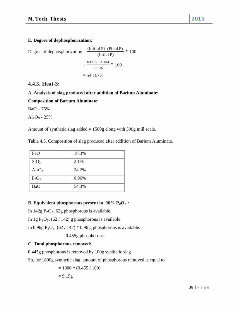
E. Degree of dephosphorization:
Degree of dephosphorization = ( )–( )
( ) * 100
=
* 100
= 54.167%
4.4.3. Heat-3:
A. Analysis of slag produced after addition of Barium Aluminate:
Composition of Barium Aluminate:
BaO – 75%
Al₂O₃ - 25%
Amount of synthetic slag added = 1500g along with 300g mill scale.
Table 4.5. Composition of slag produced after addition of Barium Aluminate.
FeO 18.3%
SiO2 2.1%
Al2O3 24.2%
P2O5 0.96%
BaO 54.3%
B. Equivalent phosphorous present in .96% P₂O₅ :
In 142g P₂O₅, 62g phosphorous is available.
In 1g P₂O₅, (62 / 142) g phosphorous is available.
In 0.96g P₂O₅, (62 / 142) * 0.96 g phosphorous is available.
= 0.455g phosphorous.
C. Total phosphorous removed:
0.445g phosphorous is removed by 100g synthetic slag.
So, for 1800g synthetic slag, amount of phosphorous removed is equal to
= 1800 * (0.455 / 100)
= 9.19g
M. Tech. Thesis 2014
39 | P a g e
Hence, in first heat 9.19g phosphorous has been removed after adding 1800g of synthetic slag.
D. Analysis of metal produced after addition of Barium Aluminate:
Initial phosphorous content in sponge iron is 0.092 wt. %
The metal sample had been collected at 1668°C.
Final phosphorous content of steel is 0.072%, which has been calculated by spectro analysis.
E. Degree of dephosphorization:
Degree of dephosphorization = ( )–( )
( ) * 100
=
* 100
= 21.74%
Degree of dephosphorization is very less in 3rd
heat because. The operating temperature was
high, while metal sample had been collected. Due to high temperature phosphorous from slag
returned back to the steel since, dephosphorization is preferable at low temperature. Thus, we
had conducted second test with Barium Aluminate as synthetic slag.
4.4.4. Heat-4:
Due to the above disadvantage of high operating temperature, in this heat the temperature was
maintained at 1610°C.
A. Analysis of slag produced after addition of Barium Aluminate:
Composition of Barium Aluminate:
BaO – 75%
Al₂O₃ - 25%
Amount of synthetic slag added = 1500g along with 300g mill scale.

M. Tech. Thesis 2014
40 | P a g e
Table 4.5. Composition of slag produced after addition of Barium Aluminate (2).
FeO 19.3%
SiO2 1.9%
Al2O3 23.9%
P2O5 2.07%
BaO 52.7%
B. Equivalent phosphorous present in 2.07% P2O5:
In 142g P₂O₅, 62g phosphorous is available.
In 1g P₂O₅, (62 / 142) g phosphorous is available.
In 2.07g P₂O₅, (62 / 142) * 2.07 g phosphorous is available.
= 0.901g phosphorous.
C. Total phosphorous removed:
0.901g phosphorous is removed by 100g synthetic slag.
So, for 1800g synthetic slag, amount of phosphorous removed is equal to
= 1800 * (0.901 / 100)
= 16.27g
Hence, in first heat 16.27g phosphorous has been removed after adding 1800g of synthetic slag.
D. Analysis of metal produced after addition of Barium Aluminate:
Initial phosphorous content in sponge iron is 0.09 wt. %
The metal sample had been collected at 1610°C.
Final phosphorous content of steel is 0.04%, which has been calculated by spectro analysis.
E. Degree of dephosphorization:
Degree of dephosphorization = ( )–( )
( ) * 100
=
* 100
= 55.55%
M. Tech. Thesis 2014
41 | P a g e
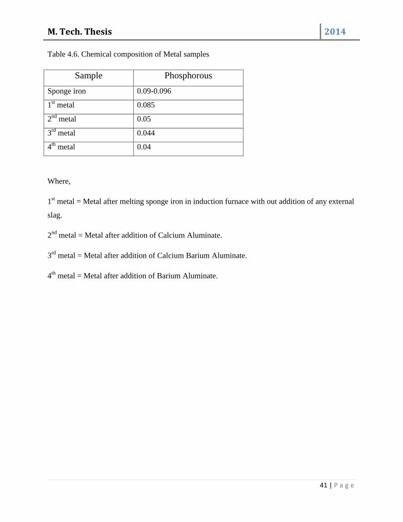
Table 4.6. Chemical composition of Metal samples
Sample Phosphorous
Sponge iron 0.09-0.096
1st metal 0.085
2nd
metal 0.05
3rd
metal 0.044
4th
metal 0.04
Where,
1st metal = Metal after melting sponge iron in induction furnace with out addition of any external
slag.
2nd
metal = Metal after addition of Calcium Aluminate.
3rd
metal = Metal after addition of Calcium Barium Aluminate.
4th
metal = Metal after addition of Barium Aluminate.

M. Tech. Thesis 2014
42 | P a g e
Chapter-5
M. Tech. Thesis 2014
43 | P a g e
5.1. Results:
In primary steel making, oxygen is used as an agent for oxidation of dissolved impurities like C,
Si, Mn and P. To some extent, iron itself is also oxidized during the process. The process is also
known as oxygen steelmaking. On the other hand, in induction furnace steel making, no direct
oxygen is introduced in the bath. The impurities are oxidized by introducing FeO in the bath. The
requirement of FeO for slag formation and oxidation of various elements is fulfilled by addition
of sponge iron. Thus, presence of FeO is important as it corresponds to oxygen potential of the
slag.
Removal of phosphorous takes place by oxidation. The product, phosphorous pentoxide is being
held by basic constituents, like CaO, present in the slag. In steel making processes basicity of the
slag is maintained by addition of calcined lime. The reaction may be given by,
[P] + 5/2[O₂] + 3/2(O-²) = (PO4-³) (1)
The oxidation reactions for other elements may be written as,
[Si] + 2(FeO) → (SiO₂) + 2[Fe] (2)
,Mn- + (FeO) → (MnO) + ,Fe- (3)
,C- + (FeO) → *CO+ + ,Fe- (4)
In the present work, dephosphorization experiments have been carried out as discussed in
previous section. Total four heats were processed using, scrap and sponge iron. During each
individual heat, the samples of slag and liquid metal have been collected. The results for metal
and slag samples are given in Table 4.6 and 5.1 respectively. The results show chemical analysis
of metal and slag samples. From the data it can be observed that degree of dephosphorization
varies from 21.74% to as high as 55.55 % for various heats.
Borovsky [10] showed that phosphorous distribution ratio i.e. (P2O5) / [P] or Up required higher
basicity’s and FeO content, lower SiO2 and Al2O3, and very low P2O5. However, FeO content
in the slag is needed to be 15–35 % for effective dephosphorization. Another very important
condition for dephosphorization is lowest possible temperature [11]. In IMF operation, slag is
removed from furnace top. Many a times it is a manual process. Increase in basicity leads to
increase in slag volume. Large slag volume makes IMF operation difficult. Moreover, upper
surface of the slag remains in contact with atmosphere which decreases slag temperature. Hence
the slag is continuously churned by rod from the top.
M. Tech. Thesis 2014
44 | P a g e
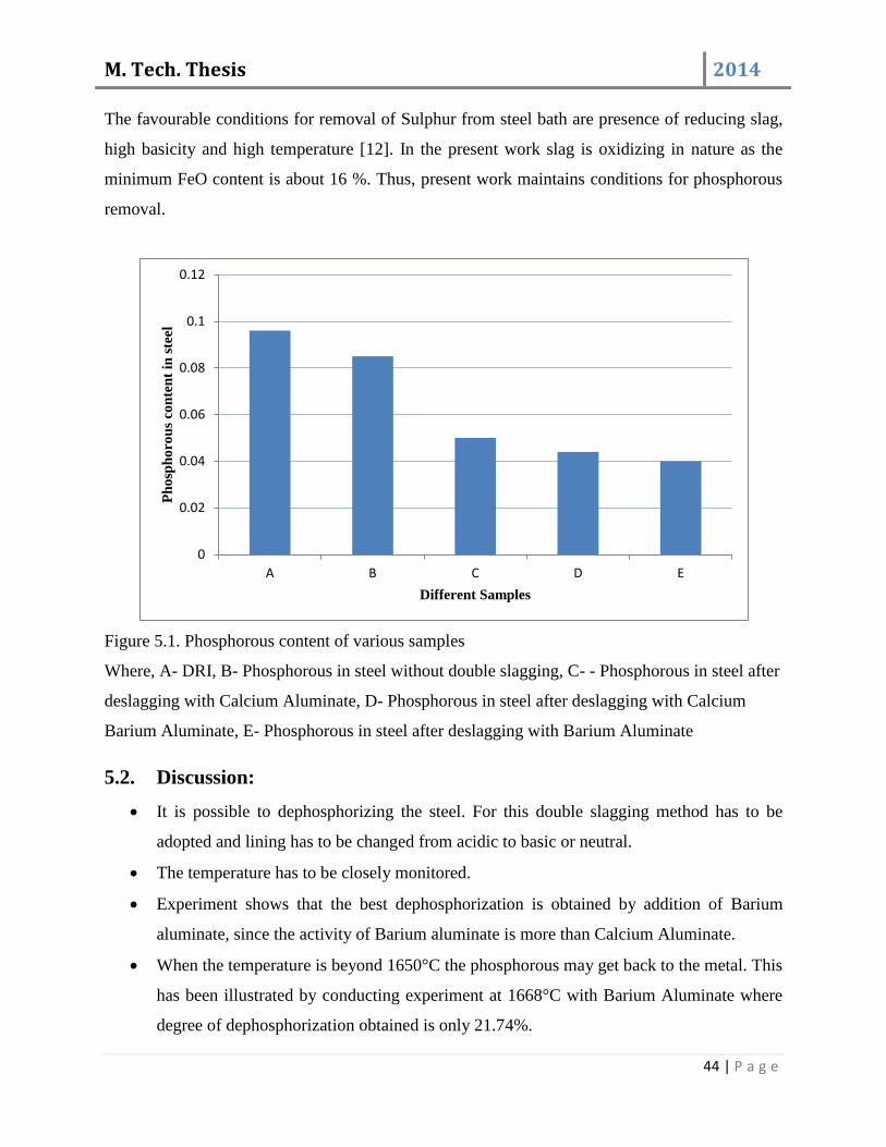
The favourable conditions for removal of Sulphur from steel bath are presence of reducing slag,
high basicity and high temperature [12]. In the present work slag is oxidizing in nature as the
minimum FeO content is about 16 %. Thus, present work maintains conditions for phosphorous
removal.
Figure 5.1. Phosphorous content of various samples
Where, A- DRI, B- Phosphorous in steel without double slagging, C- - Phosphorous in steel after
deslagging with Calcium Aluminate, D- Phosphorous in steel after deslagging with Calcium
Barium Aluminate, E- Phosphorous in steel after deslagging with Barium Aluminate
5.2. Discussion:
It is possible to dephosphorizing the steel. For this double slagging method has to be
adopted and lining has to be changed from acidic to basic or neutral.
The temperature has to be closely monitored.
Experiment shows that the best dephosphorization is obtained by addition of Barium
aluminate, since the activity of Barium aluminate is more than Calcium Aluminate.
When the temperature is beyond 1650°C the phosphorous may get back to the metal. This
has been illustrated by conducting experiment at 1668°C with Barium Aluminate where
degree of dephosphorization obtained is only 21.74%.
0
0.02
0.04
0.06
0.08
0.1
0.12
A B C D E
Ph
osp
ho
rou
s co
nte
nt
in s
teel
Different Samples

M. Tech. Thesis 2014
45 | P a g e
Table 5.1. Chemical composition of slag, operating temperature and their Degree of dephosphorization:
Heat Sample Phosphorous P₂O₅ Operation Temperature Degree of
dephosphorization
0 Slag-1 0.069 1630°C --
1 Slag-2 1.70 1602°C 47.92%
2 Slag-3 1.95 1607°C 54.17%
3 Slag-4 0.96 1668°C 21.74%
4 Slag-4 2.07 1610°C 55.55%
Where,
Slag-1 = slag which is produced after melting sponge iron
Slag-2 = slag after addition of Calcium Aluminate.
Slag-3 = slag after addition of Calcium Barium Aluminate
Slag-4 = slag after addition of Barium Aluminate.
5.3. Limitations:
The laboratory induction furnace did not provide for close temperature monitoring.
We have conducted only one experiment with each of the fluxes, for a reproductive result
number of experiments need to be conducted.

M. Tech. Thesis 2014
46 | P a g e
Chapter-6
M. Tech. Thesis 2014
47 | P a g e
6. Conclusions:
Though primary steelmaking is more popular than induction furnace steelmaking, the
metallurgical aspects of the process are needed to be studied. Removal of Sulphur and
phosphorous from steel in induction furnace route of steelmaking can be possible with neutral or
basic lining. The stirring of the molten bath in induction furnace is also important.
The project establishes beyond doubt that it is possible to dephosphorizing steel produced from
induction furnace route by,
Closely monitoring the temperature.
Double slagging has to be adopted.
Changing the acidic lining of the furnace in to a more costly basic lining or at least to a
neutral lining.
Deslagging with the Barium Aluminate gives the best result concerning
dephosphorization.
Removal of phosphorous can be achieved by maintaining basicity and FeO in the slag.
In the present work maximum 55.55% dephosphorization has been achieved.
However before making a farm decision more number of experiment has to be conducted.
M. Tech. Thesis 2014
48 | P a g e
7. References:
1. IIM, Steel Making, Chapter 7
2. Bedarkar S., Singh R. Removal of Phosphorous from Steel Produced by Melting Sponge
Iron in Induction Furnace, p 207-211.
3. Dutta S.K., studies on direct reduced iron melting in induction furnace, Vol.57, No. 5, p
467-473.
4. Internet source, Effect of Phosphorus on the Properties of Carbon Steels.
5. Plant Study guide, Adhunik Metaliks ltd.
6. Vivek R. Gandhewar, Induction Furnace - A Review. International Journal of
Engineering and Technology Vol.3 (4), pp 277-284.
7. R.H. Tupkary, An introduction to Modern Steel Making. Delhi, Khanna Publishers.2011.
8. Ghosh A., Chatterjee A., Iron and Steelmaking. New Delhi, PHI Learning Private
Limited.2012
9. ] Shukla A. and Deo B., Department of Materials and Metallurgical Engineering, Indian
Institute of Technology Kanpur, Mathematical Modeling of Phosphorous Prediction in
BOF Steelmaking Process.
10. Borovsky T., Kijak J. and Domovec M., Acta Meta. Slovaca, 16 (2010) p-165.
11. W. Trinks, Industrial furnaces. New York, London. 4th
edition 1967.
12. Turkdogan E.T., Fundamentals of Steelmaking, The Institute of Materials, London
(1996) p- 236.
13. ] Jiang T, Qiu G, Xu J, Zhu D, and Singh R, Direct Reduction of Composite Binder
Pellets and Use of DRI, Electrotherm (India) Limited, Ahmedabad (2007)p- 238.
14. Deo B and Boom R, Fundamentals of Steelmaking Metallurgy, Prentice Hall
International, UK (1993)p-73.
15. Chakrabarti A.K. Steel Making. New Delhi, PHI Learning Private Limited.2007.
16. Dutta S K, and Lele A B, Minerals and Metals Review, 23(1) (1997) p 79.
17. B.J. Monaghan, R.J. Pomfret, and K.S. Coley. The Kinetics of Dephosphorization of
Carbon-Saturated Iron Using an Oxidizing Slag.