DEPARTMENT OF THE NAVY HEADQUARTERS … 4790.7.pdf · DEPARTMENT OF THE NAVY HEADQUARTERS UNITED...
172
MCO 4790.7 LPS-4-hnl 18 Aug 1977 MARINE CORPS ORDER 4790.7 From: Commandant of the Marine Corps To: Distribution List Subj: Marine Corps Integrated Maintenance Management System Automated Information System, Headquarters Maintenance Subsystem, Headquarters Users Manual Ref: (a) MCO 4790.1A Encl: (1) (SC) USMC Document No. 4790 UM-02, Programming Documentation Standards and Specifications, Marine Corps Integrated Maintenance Management System Automated Information System, Headquarters Maintenance Subsystem 1. Purpose . To transmit the detailed procedures and instructions pertaining to the Marine Corps Integrated Maintenance Management System Automated Information System, Headquarters Maintenance Subsystem (MIMMS AIS/HMSS) (enclosure (1)). 2. Information . Reference (a) promulgated general policy, guidance, and information pertaining to MIMMS. Enclosure (1) contains the specific procedures and instructions pertaining to the MIMMS AIS/HMSS operation. 3. Action . Addressees shall ensure compliance with the contents of this Order and reference (a). 4. Recommendations . Recommendations for changes to the MIMMS AIS/HMSS and the Headquarters Users Manual are invited and should be submitted to the Commanding General (Code 730), Marine Corps Logistics Support Base, Atlantic, Albany, Georgia 31703, via the appropriate chain of command, with copies to the Commandant of the Marine Corps (Codes LMM and LPS). 5. Reserve Applicability . This Order is applicable to the Marine Corps Reserve. DISTRIBUTION: L81 plus 7000176 (20) 7000148, 160 (10) Copy to: 7000144 (2) 8145001 PCN 102 065456 00 DEPARTMENT OF THE NAVY HEADQUARTERS UNITED STATES MARINE CORPS WASHINGTON, DC 20380
-
Upload
truonghanh -
Category
Documents
-
view
218 -
download
3
Transcript of DEPARTMENT OF THE NAVY HEADQUARTERS … 4790.7.pdf · DEPARTMENT OF THE NAVY HEADQUARTERS UNITED...
MCO 4790.7 LPS-4-hnl 18 Aug 1977 MARINE CORPS ORDER 4790.7
From: Commandant of the Marine Corps To: Distribution List
Subj: Marine Corps Integrated Maintenance Management System Automated Information System, Headquarters Maintenance Subsystem, Headquarters Users Manual
Ref: (a) MCO 4790.1A
Encl: (1) (SC) USMC Document No. 4790 UM-02, Programming Documentation Standards and Specifications, Marine Corps Integrated Maintenance Management System Automated Information System, Headquarters Maintenance Subsystem
1. Purpose. To transmit the detailed procedures and instructions pertaining to the Marine Corps Integrated Maintenance Management System Automated Information System, Headquarters Maintenance Subsystem (MIMMS AIS/HMSS) (enclosure (1)).
2. Information. Reference (a) promulgated general policy, guidance, and information pertaining to MIMMS. Enclosure (1) contains the specific procedures and instructions pertaining to the MIMMS AIS/HMSS operation.
3. Action. Addressees shall ensure compliance with the contents of this Order and reference (a).
4. Recommendations. Recommendations for changes to the MIMMS AIS/HMSS and the Headquarters Users Manual are invited and should be submitted to the Commanding General (Code 730), Marine Corps Logistics Support Base, Atlantic, Albany, Georgia 31703, via the appropriate chain of command, with copies to the Commandant of the Marine Corps (Codes LMM and LPS).
5. Reserve Applicability. This Order is applicable to the Marine Corps Reserve.
DISTRIBUTION: L81 plus 7000176 (20) 7000148, 160 (10) Copy to: 7000144 (2) 8145001 PCN 102 065456 00
DEPARTMENT OF THE NAVY HEADQUARTERS UNITED STATES MARINE CORPS
WASHINGTON, DC 20380


ABSTRACT
The Marine Corps Integrated Maintenance Management System Automated Information System (MIMMS AIS) is a maintenance management information system which is designed to support commanders and logistics managers at all command levels in the execution of ground equipment maintenance management functions.
The MIMMS AIS Headquarters Maintenance Subsystem (MIMMS AIS/ HMSS) is designed to support logistics managers at Headquarters Marine Corps and the Marine Corps Logistics Support Base, Atlantic (MCLSBLant). The support is provided by requiring commodity and principal end item (PEI) managers to specify maintenance and system standards and to maintain a data base of selected maintenance information. This data base, extracted from the Field Maintenance Subsystem (MIMMS/AIS/FMSS), will permit the user to perform selective maintenance engineering analysis, logistics readiness evaluation, and maintenance management for specified functions required to be performed by the HMSS user. The system will accept input data via punched cards, magnetic tape, remote job entry (RJE) device, or source data automation (SDA) device. Output information required to maintain the system standards data is produced on a scheduled basis; all other output information will be obtained by means of an information retrieval system which is external to the HMSS, such as MARK IV. MIMMS AIS/HMSS data base files are defined for MARK IV usage.
ii
TABLE OF CONTENTS
Page
SECTION 1. GENERAL DESCRIPTION 1 1.1 Purpose of the Users Manual 1 1.2 Users Manual Organization 1 1.3 Project References 1
SECTION 2. SYSTEM SUMMARY 3 2.1 System Application 3 2.2 System Operation 4 2.2.1 User Input 4 2.2.2 Input From Other Systems 4 2.2.3 Input From MIMMS AIS/FMSS 4 2.2.4 HMSS Procedures 4 2.2.5 HMSS Data Base 5 2.2.6 HMSS User Output 5 2.2.7 Output for FMSS ASC 5 2.3 System Configuration 5 2.4 System Organization 6 2.5 Performance 8 2.6 Data Base 9 2.7 General Description of Inputs, Processing, and Outputs 11 2.7.1 Input Transactions 11 2.7.2 Processing 21 2.7.3 Outputs 21
SECTION 3. STAFF FUNCTIONS RELATED TO TECHNICAL OPERATIONS 25 3.1 Staff Input Requirements 25 3.2 Composition Rules 25 3.3 Vocabulary 25 3.4 Input Sample Formats 25 3.5 Staff Output Requirements 25 3.6 Output Sample Formats 25 3.7 Utilization of System Outputs 25
SECTION 4. FILE QUERY PROCEDURES 33 4.1 System Query Capabilities 33 4.2 Data Base Format 33 4.3 Query Preparation 34 4.4 Control Instructions 34 4.5 Sample Information Retrieval System Outputs 37 4.5.1 Equipment Reliability and Maintainability Analysis 37
iii

Page
4.5.2 Equipment Failure Analysis 40 4.5.3 Repair Part Application 46 4.5.4. Maintenance Task Analysis 46 4.5.5 Summary 50
APPENDIX A SAMPLE INPUT TRANSACTIONS AND LEGENDS FOR THE HMSS A-1
APPENDIX B SAMPLE OUTPUT REPORTS B-1
APPENDIX C DATA ELEMENTS C-1
APPENDIX D ID STANDARDS FILE D-1
APPENDIX E MI STANDARDS FILE E-1
APPENDIX F EDIT STANDARDS FILE F-1
APPENDIX G MASTER EQUIPMENT FILE G-1
APPENDIX H HISTORY FILE H-1
APPENDIX I UNIT DATA FILE I-1
APPENDIX J TAM DATA FILE J-1
APPENDIX K LOGISTICS READINESS FILE K-1
APPENDIX L MODIFICATION STATUS REPORT FILE L-1
APPENDIX M MAINTENANCE MANPOWER UTILIZATION REPORT FILE M-1
APPENDIX N SECONDARY REPARABLE EXPENSE SUMMARY REPORT FILE N-1
APPENDIX O HISTORICAL MAINTENANCE ENGINEERING FILE O-1
APPENDIX P GLOSSARY FOR HMSS FILE DEFINITIONS P-1
iv
Page
APPENDIX Q JOB IDENTIFICATION, DEFECT, AND JOB STATUS CODES Q-1 Q1.1 Job Identification Codes Q-1 Q1.2 Defect Codes Q-3 Q1.3 Job Status Codes Q-11
APPENDIX R JOB IDENTIFICATION NUMBERS R-1
APPENDIX S MIMMS DOCUMENT STATUS FILE S-1
v
LIST OF FIGURES
Figure Page
2-01 MIMMS AIS/HMSS System Organization 7
2-02 Sample MIMMS AIS ID Standards File Change Memorandum 13
2-03 MIMMS AIS ID Standards File Change Instructions 15
2-04 Sample MIMMS AIS MI Standards File Change Memorandum 18
2-05 MIMMS AIS MI Standards File Change Instructions 19
3-01 Staff Input Requirements 26
3-02 Staff Output Requirements 29
4-01 Data Retrieval Request Format 35
4-02 Data Retrieval Request Instructions 36
4-03 Sample Output Format for Equipment Reliability-Maintainability Analysis 38
4-04 Reliability/Maintainability Performance Indicators (Man-Hour) 41
4-05 Reliability/Maintainability Performance Indicators (Materiel Expense) 42
4-06 Sample Out Format for Malfunction Analysis 43
4-07 Sample Output Format for Equipment Failure Repair Analysis 44
4-08 Sample Output Format for Repair Part End Item Application 47
4-09 Sample Output Format for Repair Part Secondary Reparable Application 48
4-10 Sample Output Format for Maintenance Task Analysis 49
vi

_________________________________________________________________ | | | RECORD OF CHANGES | |_______________________________________________________________| | CHANGE | DATA OF | DATE | BY WHOM | | NUMBER | CHANGE | ENTERED | ENTERED | |________|_____________|_____________|__________________________| | | | | | |________|_____________|_____________|__________________________| | | | | | |________|_____________|_____________|__________________________| | | | | | |________|_____________|_____________|__________________________| | | | | | |________|_____________|_____________|__________________________| | | | | | |________|_____________|_____________|__________________________| | | | | | |________|_____________|_____________|__________________________| | | | | | |________|_____________|_____________|__________________________| | | | | | |________|_____________|_____________|__________________________| | | | | | |________|_____________|_____________|__________________________| | | | | | |________|_____________|_____________|__________________________|
vii

SECTION 1. GENERAL DESCRIPTION
1.1 Purpose of the Users Manual. The objective of the Users Manual for the MIMMS AIS/HMSS is to provide nonautomated data processing (ADP) personnel at Headquarters Marine Corps and the MCLSBLant with the necessary information to effectively use the HMSS.
1.2 Users Manual Organization This Users Manual is structured in accordance with SECNAVINST 5233.1A and DoD 4120.17-M. Appendixes A through S of the Users Manual have been included to provide further amplification of system inputs, master files, data elements, and output reports to the system users.
1.3 Project References. Project references applicable to the history and development of the system are listed below. None of these references carry a security classification. The MIMMS AIS project sponsor is the Commandant of the Marine Corps (Code LM). The HMSS users are the commodity managers and PEI managers of ground equipment in the Marine Corps inventory. The HMSS will operate at the MCLSBLant.
a. Project request is Project Order No. PO-O-T551.
b. The Total Revision and Upgrading of Maintenance Procedure (TRUMP) Phase I Report (Volumes I and II); Autonetics Division, North American Rockwell Company; 19 July 1968.
c. The Total Revision and Upgradint of Maintenance procedures (TRUMP) Phase II Report (Volumes I, II, and III); North American Rockwell Information Systems Company; 31 January 1970.
d. MIMMS System Design Specifications; General Services Administration - Region 3; undated (1971 was year of completion).
e. MIMMS System Design Specification (Revised); General Services Administration - Region 3; undated (1973 was year of completion).
f. DoD 4120.17-M, Department of Defense Automated Data Systems Documentation Standards Manual.
1

g. MCO 3000.12, Marine Corps Automated Readiness Evaluation System, Logistics, User Procedures (MIMMS/MARES Log).
h. MCO 4790.5, Marine Corps Integrated Maintenance Management System Automated Information System, Field Maintenance Subsystem, Field Users Procedures.
2

SECTION 2. SYSTEM SUMMARY
2.1 System Application. The MIMMS AIS/HMSS supports its users by providing a data base of standards information and selected maintenance information. The data base contains equipment (item designator (ID)) standards, modification (modification instruction (MI)) standards, and edit (ED) standards. The standards data base will be used primarily to validate user input in the MIMMS AIS/FMSS. The selected maintenance information consists of maintenance engineering, logistics readiness, modification control, and document status data. This selected maintenance information is required for effective maintenance management within the Marine Corps. The capabilities of MIMMS AIS/FMSS are:
a. Establishment of a ground equipment maintenance management information system.
b. Automatic gathering, at the field maintenance subsystem (FMSS) level, of relevant maintenance management information and automatic data base updating and maintaining at the HMSS level.
c. Provides centralized control of standards data applicable throughout the Marine Corps ground equipment inventory.
d. Flexibility in controlling the type of maintenance management information to be gathered by the FMSS.
e. Flexibility in extracting and formatting meaningful maintenance management information from the HMSS data base.
f. Standardization of maintenance management functions performed throughout the Marine Corps.
g. Continuous availability of detailed maintenance engineering data at the Headquarters Marine Corps level.
3

2.2 System Operation. The functional manager for all logistics information systems is the Commandant of the Marine Corps (Code L). The system sponsor for the HMSS is the Commanding General, Marine Corps Logistics Support Base, Atlantic. The responsibilities of each of these managers are established in the current editions of MCO P5200.15 and MCO 5230.8.
2.2.1 User Input. The MIMMS AIS/HMSS users will normally be commodity managers at Headquarters Marine Corps and PEI managers at the MCLSBLant. Each system users is responsible for maintaining the system standards data for equipment types under his/her purview. System standards data is updated with the use of the following transactions;
a. ID standards data transaction
b. MI standards data transaction
c. ED standards data transaction
d. Unit data (UD) transaction
e. Table of authorized materiel (TAM) data (TD) transaction
The formats for these transactions are illustrated in Appendix A. More detailed descriptions of the transactions are provided in paragraph 2.7 of this Manual.
2.2.2 Input From Other Systems. Certain data elements of the system standards data are updated by an automated interface with logistics information systems resident at the MCLSBLant. These are accomplished quarterly.
2.2.3 Input From MIMMS AIS/FMSS. Extracts from the MIMMS AIS/FMSS are made by each force automated service center (FASC) on a scheduled basis and sent to the MCLSBLant to update MIMMS AIS/HMSS files. These extracts contain maintenance engineering, modification control, document status, and logistics readiness information.
2.2.4 HMSS Procedures. The HMSS data base procedures consist of editing and validating input transactions, validating FMSS input for completeness, updating HMSS files, maintaining HMSS maintaining HMSS files, extracting output information from the HMSS files, and producing output information for the HMSS
4

user and the FMSS. Execution of HMSS procedures occurs at various times; i.e., input transactions are edited and validated as requested by the functional manager, equipment standards data are updated on a semiannual basis, modification control and edit standards data update system files on an as-required basis, while logistics readiness data is updated on a weekly basis.
2.2.5 HMSS Data Base. The HMSS data base consists of the HMSS files described in Appendixes D through O.
2.2.6 HMSS User Output. The output reports which the HMSS user receives from the system are divided into two categories: system reports and as-requested output. Sample output reports are shown in Appendix B and explained in paragraph 2.7. Section 4 contains some sample as-requested output which could be extracted from the system, using the MARK IV information retrieval function.
2.2.7 Output for FMSS ASC. When the HMSS procedures update the ID standards, MI standards, or ED standards files, the FMSS’s must have their respective standards files updated. To accomplish this, the HMSS produces a quarterly standards tape, one for each FMSS ASC, which will contain the complete, updated standards files and replace the respective existing files in the FMSS. The tapes are mailed from the HMSS CDPA.
2.3 System Configuration. The MIMMS AIS/HMSS programs are designed to operate using an IBM S360 computer. The basic IBM S360 hardware configuration required to support the HMSS consists of the following:
a. Central processing unit
b. Three tape devices
c. Two work disks
d. Two storage disks
e. One printer
f. One card reader
g. Several SDA devices (optional)
h. Several RJE devices (optional)
5
i. One computer output microfilm (COM) device
j. One Xerox 1200 device (optional)
System configuration with the preceding hardware will allow entry of input data by SDA and RJE devices, output of reports via RJE device, and production of voluminous output reports on microfilm instead of printed reports.
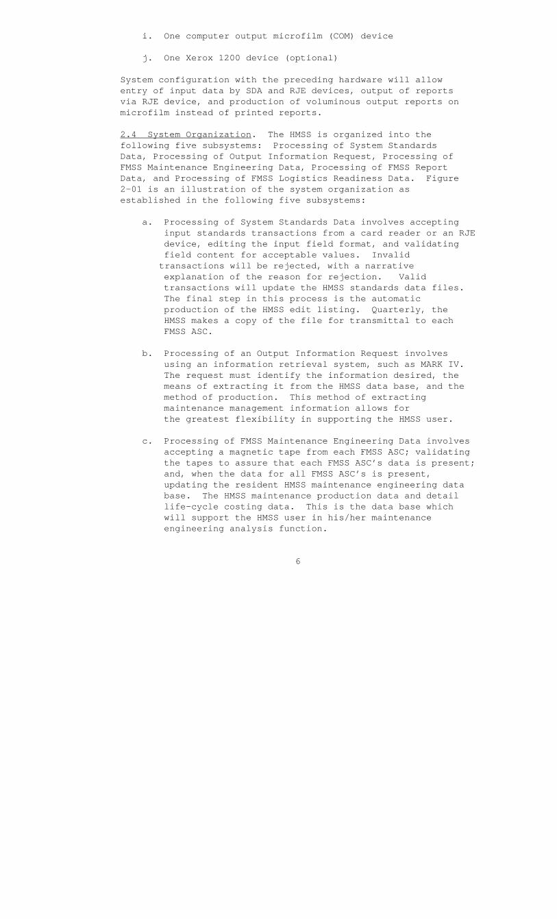
2.4 System Organization. The HMSS is organized into the following five subsystems: Processing of System Standards Data, Processing of Output Information Request, Processing of FMSS Maintenance Engineering Data, Processing of FMSS Report Data, and Processing of FMSS Logistics Readiness Data. Figure 2-01 is an illustration of the system organization as established in the following five subsystems:
a. Processing of System Standards Data involves accepting input standards transactions from a card reader or an RJE device, editing the input field format, and validating field content for acceptable values. Invalid transactions will be rejected, with a narrative explanation of the reason for rejection. Valid transactions will update the HMSS standards data files. The final step in this process is the automatic production of the HMSS edit listing. Quarterly, the HMSS makes a copy of the file for transmittal to each FMSS ASC.
b. Processing of an Output Information Request involves using an information retrieval system, such as MARK IV. The request must identify the information desired, the means of extracting it from the HMSS data base, and the method of production. This method of extracting maintenance management information allows for the greatest flexibility in supporting the HMSS user.
c. Processing of FMSS Maintenance Engineering Data involves accepting a magnetic tape from each FMSS ASC; validating the tapes to assure that each FMSS ASC’s data is present; and, when the data for all FMSS ASC’s is present, updating the resident HMSS maintenance engineering data base. The HMSS maintenance production data and detail life-cycle costing data. This is the data base which will support the HMSS user in his/her maintenance engineering analysis function.
6

d. Processing of the FMSS Report Control Data involves accepting FMSS data for the modification status, maintenance manpower utilization, and secondary reparable summary reports; validating the completeness of data transmitted; and updating of the respective report file.
e. Processing of the FMSS Logistics Readiness Data involves accepting a magnetic tape or cards from the FMSS ASC’s, validating the tape and/or card formats, and updating the HMSS logistics readiness data base.
2.5 Performance.
a. The primary HMSS input function performed by the HMSS user is to maintain the MIMMS data base by specifying what equipment type and the scope of the maintenance engineering data to be gathered by the FMSS. The HMSS has the following five input transactions, illustrated in Appendix A, which maintain the MIMMS data base:
(1) ID standards data transaction
(2) MI standards data transaction
(3) Edit standards data transaction
(4) Unit data transaction
(5) TAM data transaction
b. The volume and rate of submission of input transactions depend on the frequency with which the HMSS user requires different maintenance engineering data, the frequency with which modifications must be made to equipments in the MIMMS AIS inventory, and the frequency with which edit standards and logistics readiness standards change.
c. Data received from the FMSS and input to the HMSS is entered via AUTODIN card or magnetic tape from each FMSS ASC. These tapes/cards will be sent once every week for logistics readiness data and once every quarter for all other data.
8

d. HMSS output information is produced on an automatic and as-requested basis. On an automatic basis, the HMSS user will receive the edit listing. The automatic and as-requested output are shown in Appendix B. Job identification numbers are listed in Appendix R.
e. As-requested output information can be provided at any time. However, for as-requested output, the HMSS user must specify the data to be extracted and the format for production. There is no limit, at this time, on the number of requests which may be submitted. Only HMSS users authorized by the Commandant of the Marine Corps (Code LMM) or the Commanding General (Code 730), MCLSBLant, to extract information from the HMSS data base can submit report requests. The requester is limited to the data elements in the data base and must ensure that he/she understands the significance and relationship of the information contained in the data base. As a reference, the user should consult the data base element descriptions in Appendix C and the file definitions in Appendix P.
2.6 Data Base. The files of the HMSS located at the CDPA, MCLSBLant, are the data base for the system. The data base consists of the following files with a brief description for each file. The contents of each file are shown in Appendixes D through O.
a. The ID standards file identifies to the MIMMS AIS equipment types to be managed by the system; and it also specifies, for an ID, what type of maintenance engineering data will be gathered in the FMSS.
b. The MI standards file identifies to the system those modifications which are applicable to the equipment types listed on the ID standards file. A record on this file will also indicate any limiting factors (by serial number) on the applicability of the MI.
c. The edit standards file consists of a number of tables which contain defect codes, job status codes, and job identification codes. These codes are used in validating input transactions for proper data entries and during
9
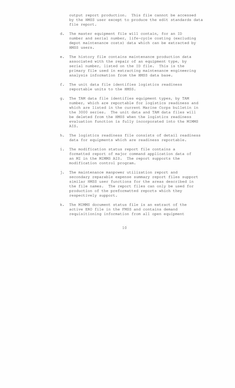
output report production. This file cannot be accessed by the HMSS user except to produce the edit standards data file report.
d. The master equipment file will contain, for an ID number and serial number, life-cycle costing (excluding depot maintenance costs) data which can be extracted by HMSS users.
e. The history file contains maintenance production data associated with the repair of an equipment type, by serial number, listed on the ID file. This is the primary file used in extracting maintenance engineering analysis information from the HMSS data base.
f. The unit data file identifies logistics readiness reportable units to the HMSS.
g. The TAM data file identifies equipment types, by TAM number, which are reportable for logistics readiness and which are listed in the current Marine Corps bulletin in the 3000 series. The unit data and TAM data files will be deleted from the HMSS when the logistics readiness evaluation function is fully incorporated into the MIMMS AIS.
h. The logistics readiness file consists of detail readiness data for equipments which are readiness reportable.
i. The modification status report file contains a formatted report of major command application data of an MI in the MIMMS AIS. The report supports the modification control program.
j. The maintenance manpower utilization report and secondary reparable expense summary report files support similar HMSS user functions for the areas described in the file names. The report files can only be used for production of the preformatted reports which they respectively support.
k. The MIMMS document status file is an extract of the active ERO file in the FMSS and contains demand requisitioning information from all open equipment
10

repair orders (ERO’s) assigned Category Code M, D, F, O, or H. For each TAM control number (TAMCN), ID number, (TAMCN), ID number, and serial number, the document number, national stock number (NSN), quantity, priority, status, and status date are presented.
1. The historical maintenance engineering file, at this time a future system enhancement, will contain extracted maintenance engineering data for equipment types, by ID number, which were deleted from MIMMS AIS management. This file is used to support historical maintenance engineering information requests.
2.7 General Description of Inputs, Processing, and Outputs. The MIMMS AIS/HMSS consists of input transactions, magnetic tape input functions, a data base update function, magnetic tape output functions, and output reports. A detailed description of the input transaction is provided in this Section and illustrated in Appendix A. A detailed description of the system output is provided in this Section and illustrated in Appendix B.
2.7.1 Input Transactions.
a. ID Standards Data Transaction. The purpose of the ID standards data transaction is to identify to the MIMMS AIS an equipment type and its associated standards data to the system, to record any subsequent changes to such standards data, or to delete the identity from system files. This transaction should be submitted and successfully processed before a related MI standards data transaction is submitted to the system. The ID standards data transaction consists of six input card types with Transaction Codes 01 through 06. Appendix A, pages A-2 through A-9, contains sample ID standards data transactions for the transactions explained in the following paragraphs.
(1) "01" Transaction Type. The "01" input transaction card type is used to establish an active ID record on the MIMMS AIS ID standards file. This transaction type specifies which equipment type, by ID number, is to be managed for maintenance engineering analysis, modification control, and readiness reporting.
(2) "02" Transaction Type. The "02" input transaction card type is used to enter standards data into
11

the ID standards file and may be submitted subsequent to or concurrent with a "01" transaction type for the same equipment type.
(3) "03" Transaction Type. The "03" transaction card type is used to delete an active ID record from the MIMMS AIS ID standards file.
(4) "04" Transaction Type. The "04" transaction card type is used to change the standards data field entries on the ID standards file for the equipment type identified by the ID.
(5) "05" Transaction Type. The "05" transaction card type has the same function as the "04" transaction type, except that different standards data fields are affected.
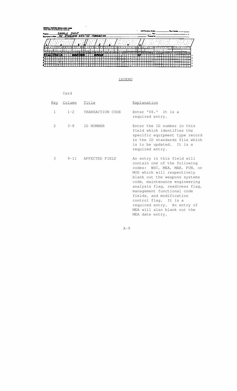
(6) "06" Transaction Type. The "06" transaction card type is used to blank out certain data fields on a specific ID on the ID standards file.
(7) Origin. The ID standards data transactions are prepared by staff personnel at Headquarters Marine Corps (Code LMM). The transactions are prepared based on the ID standards data memorandum shown in Figure 2-02. This memorandum is prepared by acquisition project officers (APO’s)/commodity managers at Headquarters Marine Corps at the time the advanced logistics order (ALO) is issued or 6 months prior to fielding the equipment. Changes or deletions will normally be submitted to correspond to the semiannual review of standards data. Additional instructions for preparing the memorandum in Figure 2-02 are contained in Figure 2-03 of this Manual and the MIMMS Headquarters Marine Corps Procedures Manual (MCO P4790.4).
b. MI Standards Data Transaction. The purpose of the MI standards data transaction is to identify to the MIMMS AIS those MI’s which are applicable to equipment types managed within the MIMMS AIS. The MI transaction consists of four input card types with Transaction Codes 11, 15, 16, and 17. The following subparagraphs will describe each of the input transaction card types. (See Appendix A, pages A-10 through A-13.)
(1) "11" Transaction Type. The "11" input transaction card type is used to establish an addition to the list of applicable MI’s within the MIMMS AIS MI standards file.
12

4797
DATE:
FROM: TO : Head, Maintenance Production Management Branch
SUBJ: MIMMS AIS ID standards file; change to
1. It is requested that the following (add/change/delete) be made to the subject file:
a. TAMCN__ __ __ __ __ ID No. __ __ __ __
b. Nomenclature:
c. Weapons System Code __ __ Readiness Flag M/X
d. NSN __ __ __ __ __ __ __ __ __ __ ____ __ __
e. Equipment Operating Time Code, Miles, Hours. Rounds, Days
f. Management Function Code__ __
g. Standard Unit Price__ __ __ __ __ __ __ __ __
2. It is desired that maintenance engineer analysis be conducted.
a. All analysis (A), failure analysis (B), repair part analysis (C), or reliability/ maintainability analysis (D). Mod Control Y/N.
b. MTBR__ __ __ __ MTBM__ __ __ __ MMT__ __ __ __
c. MTTR (2)__ __ __ __ MTTR (3) __ __ __ __ MTTR (4) _ __ _ d. MEA Date__ __ __ __ EOTC__ __ __ __ (Life Expectancy)
FIGURE 2-02. Sample MIMMS AIS ID Standards File Change Memorandum (Page 1 of 2)
13
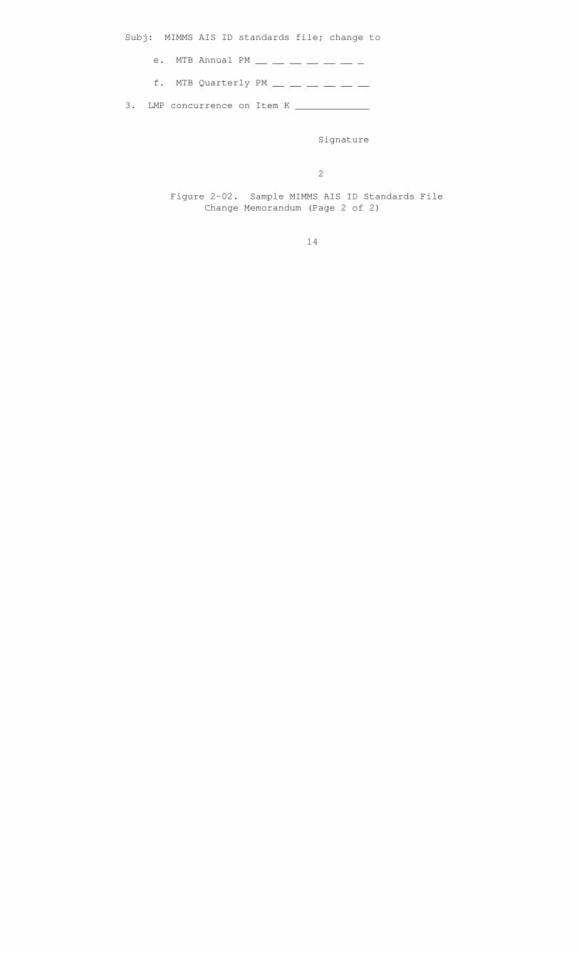
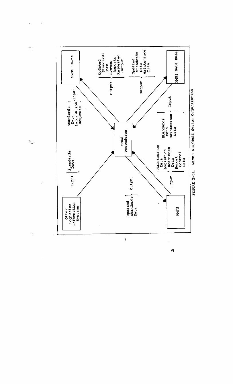
Subj: MIMMS AIS ID standards file; change to
e. MTB Annual PM __ __ __ __ __ __ _
f. MTB Quarterly PM __ __ __ __ __ __
3. LMP concurrence on Item K _____________
Signature
2
Figure 2-02. Sample MIMMS AIS ID Standards File Change Memorandum (Page 2 of 2)
14
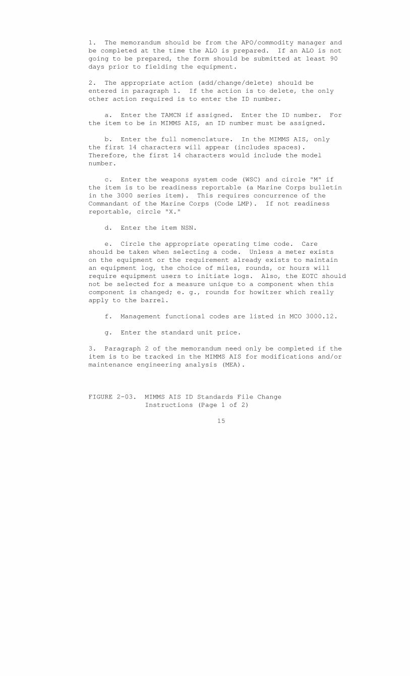
1. The memorandum should be from the APO/commodity manager and be completed at the time the ALO is prepared. If an ALO is not going to be prepared, the form should be submitted at least 90 days prior to fielding the equipment.
2. The appropriate action (add/change/delete) should be entered in paragraph 1. If the action is to delete, the only other action required is to enter the ID number.
a. Enter the TAMCN if assigned. Enter the ID number. For the item to be in MIMMS AIS, an ID number must be assigned.
b. Enter the full nomenclature. In the MIMMS AIS, only the first 14 characters will appear (includes spaces). Therefore, the first 14 characters would include the model number.
c. Enter the weapons system code (WSC) and circle "M" if the item is to be readiness reportable (a Marine Corps bulletin in the 3000 series item). This requires concurrence of the Commandant of the Marine Corps (Code LMP). If not readiness reportable, circle "X."
d. Enter the item NSN.
e. Circle the appropriate operating time code. Care should be taken when selecting a code. Unless a meter exists on the equipment or the requirement already exists to maintain an equipment log, the choice of miles, rounds, or hours will require equipment users to initiate logs. Also, the EOTC should not be selected for a measure unique to a component when this component is changed; e. g., rounds for howitzer which really apply to the barrel.
f. Management functional codes are listed in MCO 3000.12.
g. Enter the standard unit price.
3. Paragraph 2 of the memorandum need only be completed if the item is to be tracked in the MIMMS AIS for modifications and/or maintenance engineering analysis (MEA).
FIGURE 2-03. MIMMS AIS ID Standards File Change Instructions (Page 1 of 2)
15

a. Circle the letter representing the type of MEA required. Code A will receive all types. Circle "Y" (Yes) or "N" (No) for modification control. If modification control is selected, then one of the MEA codes must be selected.
b. Enter the appropriate times as developed by the integrated logistics support plan (ILSP), contractor, or other service. These figures must be in the same units as equipment operating time code (EOTC).
c. Enter the appropriate maintenance times in hours.
d. Enter data MEA is to begin year and Julian date; enter life expectancy in EOTC units.
e. Enter the maximum time between annual preventive maintenance (PM) in EOTC units.
f. Enter the maximum time between quarterly PM in EOTC units.
4. If the item is to be MIMMS readiness reportable, the assignment of a WSC and flag require the Commandant of the Marine Corps (Code LMP) concurrence.
FIGURE 2-03. MIMMS AIS ID Standards File Change Instructions (Page 2 of 2)
16

(2) "15" Transaction Type. The "15" input transaction card type is used to limit applicability of an MI to a range of serial numbers for the specified ID number. The card type is also used to make changes and deletions of serial number ranges on the MI standards file.
(3) "16" Transaction Type. The "16" input transaction card type is submitted subsequent to an "11" transaction type submission. The purpose is to make corrections or changes to data previously entered into or omitted from the MI standards file.
(4) "17" Transaction Type. The "17" input transaction card type is used to delete an MI record from the MI standards file. A "17" transaction type submission will delete the specified MI record and all associated trailer records.
(5) Origin. MI standards data transactions are prepared by staff personnel at Headquarters Marine Corps (Code LMM). The transactions are prepared based on the MI standards data memorandum shown in Figure 2-04. This memorandum is prepared by APO’s/commodity managers at Headquarters Marine Corps at the time the MI is approved. Additional instructions for preparing the memorandum in Figure 2-04 are contained in Figure 2-05 of this Manual and the MIMMS HQMC Procedures Manual (MCO P4790.4).
c. Edit Standards Data Transaction. The purpose of the edit standards data transaction is to enter into the MIMMS AIS standards data to be used in the FMSS to validate input data. The edit standards data transaction consists of five card types which have Transaction Codes DF1, DF2, JBS, J11, and J12. This transaction will update the edit standards file when the quarterly process cycle is executed. The following subparagraphs describe each of the input transaction card types by explaining the content of the keyed input transaction fields. (See Appendix A, pages A-14 through A-18.)
(1) "DF1" Transaction Type. The "DF1" input transaction card type is used to add to the edit standards file the first character of a defect code.
(2) "DF2" Transaction Type. The "DF2" input transaction card type is used to add to the edit standards file the second and third characters of a defect code.
17

4797
DATE:
FROM:
TO : Head, Maintenance Production Management Branch
SUBJ: MIMMS AIS MI standards file; change to
1. It is requested that the following (add/change/delete) be made to the subject file:
a. MI number____________________
b. ID number__ __ __ __ __ __ __ __ __ __ __ __ __ __ __ __ __ __
c. Standard Time to Modify __ __ __ __ hours.
d. Mod Kit NSN __ __ __ __ __ __ __ __ __ __ __
e. WSC __ __
2. The above modification will result in a change in the equipment ID number to __ __ __ __ __ __
3. The above modification is applicable only to certain serial numbers of the fleet.
Ser From___________________To____________________
Ser From___________________To____________________
Ser From___________________To____________________
Signature
FIGURE 2-04. Sample MIMMS AIS MI Standards File Change Memorandum
18

1. Insert the appropriate transaction type; i.e., add, change, or delete.
a. List the MI number. To be tracked, it must be an MI.
b. Enter ID numbers of equipment types the MI is applicable to. All equipments must be listed.
c. Enter the standard time to modify. Time is in hours down to tenths.
d. Enter the NSN of the modification kit.
e. If assigned, enter the equipment WSC.
2. If the modification will result in the equipment having a new ID number, enter the new ID number.
3. If the modification is only applicable to selected items of the fleet, enter the serial number ranges of those items to be modified.
FIGURE 2-05. MIMMS AIS MI Standards File Change Instructions
19

(3) "JBS" Transaction Type. The "JBS" input transaction card type is used to add to the edit standards file a job status code.
(4) "JI1" Transaction Type. The "JI1" input transaction card type is used to add to the edit standards file the first character of a job identification code.
(5) Origin. Edit standards data transactions are submitted by the Commanding General (Code 730), MCLSBLant, as part of the system modification process.
d. Unit Data Transaction. The purpose of the unit data transaction is to identify to the system a MIMMS-supported unit which is required to report to the logistics readiness system. In addition to providing the unit identification code (UIC), the transaction also enters into the unit data file the unit’s name, major command indicator, Marine Amphibious Force (MAF) code, and type of unit code (TUC). Data from this transaction is used to support the logistics readiness evaluation function at the Headquarters Marine Corps level. This transaction is prepared and submitted at any time by the Commanding General, MCLSBLant. When this transaction is processed, it will update the unit data file. (See Appendix A, page A-19.)
e. TAM Data Transaction. The purpose of the TAM data transaction is to identify to the system those equipment types, by TAM number, which are logistics readiness reportable in accordance with the current Marine Corps bulletin in the 3000 series. In addition to the reportable TAM number, the transaction provides the equipment type nomenclature and management functional code. Data from this transaction is used to support the logistics readiness evaluation function at the Headquarters Marine Corps level. This transaction is prepared and submitted at any time by the Commanding General, MCLSBLant. When this transaction is processed, it will update the TAM data file. (See Appendix A, page A-20.)
f. Magnetic Tape Input Transactions From FMSS. The following files in the HMSS are updated on a weekly or quarterly basis with current data from the FMSS:
(1) Master equipment file (quarterly)
(2) History file (quarterly)
20
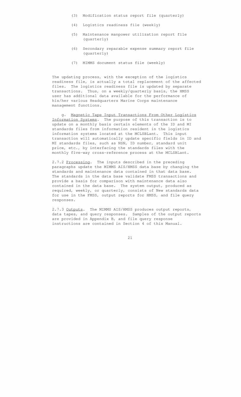
(3) Modification status report file (quarterly)
(4) Logistics readiness file (weekly)
(5) Maintenance manpower utilization report file (quarterly)
(6) Secondary reparable expense summary report file (quarterly)
(7) MIMMS document status file (weekly)
The updating process, with the exception of the logistics readiness file, is actually a total replacement of the affected files. The logistics readiness file is updated by separate transactions. Thus, on a weekly/quarterly basis, the HMSS user has additional data available for the performance of his/her various Headquarters Marine Corps maintenance management functions.
g. Magnetic Tape Input Transactions From Other Logistics Information Systems. The purpose of this transaction is to update on a monthly basis certain elements of the ID and MI standards files from information resident in the logistics information systems located at the MCLSBLant. This input transaction will automatically update specific fields in ID and MI standards files, such as NSN, ID number, standard unit price, etc., by interfacing the standards files with the monthly five-way cross-reference process at the MCLSBLant.
2.7.2 Processing. The inputs described in the preceding paragraphs update the MIMMS AIS/HMSS data base by changing the standards and maintenance data contained in that data base. The standards in the data base validate FMSS transactions and provide a basis for comparison with maintenance data also contained in the data base. The system output, produced as required, weekly, or quarterly, consists of New standards data for use in the FMSS, output reports for HMSS, and file query responses.
2.7.3 Outputs. The MIMMS AIS/HMSS produces output reports, data tapes, and query responses. Samples of the output reports are provided in Appendix B, and file query response instructions are contained in Section 4 of this Manual.
21

a. Edit Listing. This report is automatically produced whenever an input transaction is submitted for HMSS processing. This report provides the HMSS user with an audit trail of transactions which were submitted and either processed or not processed, including error messages. (See Appendix B, page B-2.)
b. ID Standards Data File Report. This preformatted report will list, in alphanumeric ID sequence, each record on the file. The purpose of the report is to provide visibility to the HMSS user of standards data associated with an equipment type, by ID number, for which the MIMMS AIS must perform some maintenance data gathering function. This report is prepared semiannually (July and January) and distributed to all HMSS users. (See Appendix B, page B-3.)
c. MI Standards Data File Report. This report will list, in alphanumeric ID number and MI number sequence, each record on the MI standards file. Serial number ranges will be listed in the trailer sequence in which they were coded. The purpose of the report is to provide the HMSS user visibility of MI standards data applicable to equipment types managed by the MIMMS AIS. This report is prepared annually (July and January) and distributed to all HMSS users. See Appendix B, page B-4.)
d. Edit Standards Data File Report. This report will list, in alphanumeric sequence and from top to bottom, all defect codes, job status codes, and job identification codes which are resident in the HMSS. The purpose of the report is to provide visibility to the HMSS user of standards data which are used in editing and validating input transaction field entries submitted at the FMSS. This report is prepared semiannually (July and January) and distributed to all HMSS users. (See Appendix B, page B-5.)
e. Modification Status Report. This report is received from the FMSS on a quarterly basis and provides modification application status for major commands supported by the MIMMS AIS. The report will primarily list, for a major command, by unit, ID number, and applicable MI numbers, the number of equipments which initially required the modification and the number of modifications completed. The report is distributed to HMSS users. (See Appendix B, page B-6.)
22
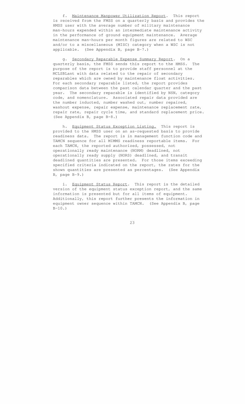
f. Maintenance Manpower Utilization Report. This report is received from the FMSS on a quarterly basis and provides the HMSS user with the average number of military maintenance man-hours expended within an intermediate maintenance activity in the performance of ground equipment maintenance. Average maintenance man-hours per month figures are related to WSC and/or to a miscellaneous (MISC) category when a WSC is not applicable. (See Appendix B, page B-7.)
g. Secondary Reparable Expense Summary Report. On a quarterly basis, the FMSS sends this report to the HMSS. The purpose of the report is to provide staff personnel at the MCLSBLant with data related to the repair of secondary reparables which are owned by maintenance float activities. For each secondary reparable listed, the report provides comparison data between the past calendar quarter and the past year. The secondary reparable is identified by NSN, category code, and nomenclature. Associated repair data provided are the number inducted, number washed out, number repaired, washout expense, repair expense, maintenance replacement rate, repair rate, repair cycle time, and standard replacement price. (See Appendix B, page B-8.)
h. Equipment Status Exception Listing. This report is provided to the HMSS user on an as-requested basis to provide readiness data. The report is in management function code and TAMCN sequence for all MIMMS readiness reportable items. For each TAMCN, the reported authorized, possessed, not operationally ready maintenance (NORM) deadlined, not operationally ready supply (NORS) deadlined, and transit deadlined quantities are presented. For those items exceeding specified criteria indicated on the report, the rates for the shown quantities are presented as percentages. (See Appendix B, page B-9.)
i. Equipment Status Report. This report is the detailed version of the equipment status exception report, and the same information is presented but for all items of equipment. Additionally, this report further presents the information in equipment owner sequence within TAMCN. (See Appendix B, page B-10.)
23
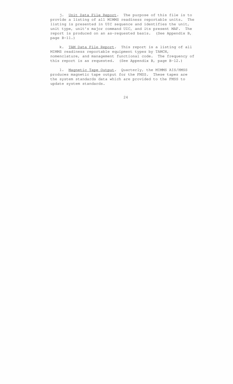
j. Unit Data File Report. The purpose of this file is to provide a listing of all MIMMS readiness reportable units. The listing is presented in UIC sequence and identifies the unit, unit type, unit’s major command UIC, and its present MAF. The report is produced on an as-requested basis. (See Appendix B, page B-11.)
k. TAM Data File Report. This report is a listing of all MIMMS readiness reportable equipment types by TAMCN, nomenclature, and management functional code. The frequency of this report is as requested. (See Appendix B, page B-12.)
l. Magnetic Tape Output. Quarterly, the MIMMS AIS/HMSS produces magnetic tape output for the FMSS. These tapes are the system standards data which are provided to the FMSS to update system standards.
24
SECTION 3. STAFF FUNCTIONS RELATED TO TECHNICAL OPERATIONS
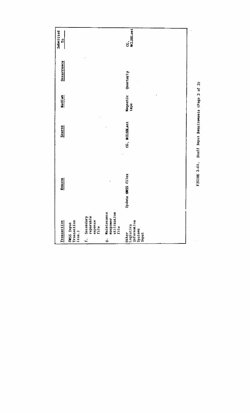
3.1 Staff Input Requirements. The MIMMS AIS/HMSS inputs which are prepared by HMSS users are explained in paragraph 2.7.1 and illustrated in Appendix A. Figure 3-01 is a tabular illustration of these inputs, the cause and time of the input, source of the input, and medium to be used.
3.2 Composition Rules. The HMSS input transactions are prepared in accordance with the criteria established for input data acceptance by a computer program written in COBOL, the computer language used for the HMSS. Each input transaction will be edited for acceptable character combinations and length. The five HMSS input transactions affected are the ID standards data, MI standards data, edit standards data, unit data, and TAM data transactions. Composition rules for these transactions are contained in paragraphs 3.3 and 3.4.
3.3 Vocabulary. Appendix C contains the definitions, abbreviations, and, where applicable, the input source of the data elements found in the HMSS. It also provides the user with the acceptable character combination codes as well as the length and explanation of the codes for system processing.
3.4 Input Sample Format. Input formats are illustrated in Appendix A with instructions keyed to each data element provided for each sample input. Figure 3-01 illustrates the input requirements.
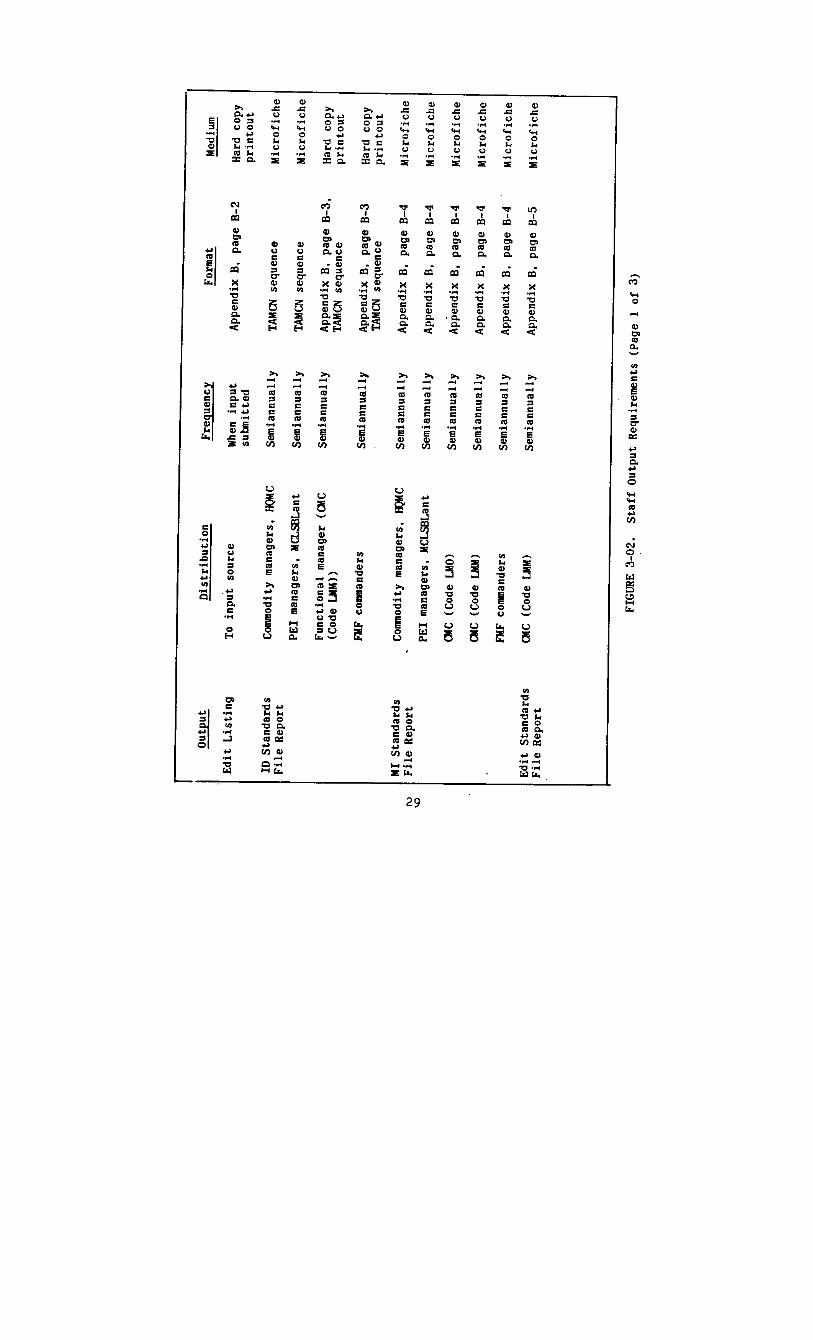
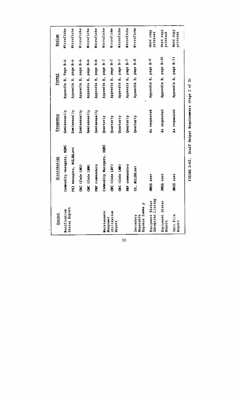
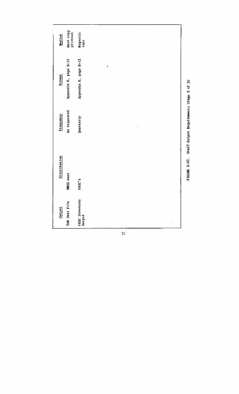
3.5 Staff Output Requirements. The MIMMS AIS/HMSS inputs which are provided the HMSS users and the FMSS are explained in paragraph 2.7.3 and illustrated in Appendix B. Figure 3-02 is an illustration of the system outputs, their distribution, frequency, and medium.
3.6 Output Sample Formats. Output formats are illustrated in Appendix B. Each sample output in Appendix B has a description and use paragraph appended.
3.7 Utilization of System Outputs. The HMSS utilization of the system outputs and byproducts can be summarized as providing the HMSS user a means of auditing his/her inputs to the HMSS, maintaining standards data in the HMSS data base and for the entire MIMMS AIS, and supporting the management functions of modification control, maintenance man-hour analysis, and secondary reparable expense analysis. Detailed utilization of the individual reports is contained in Appendix B and Section 4.
25


SECTION 4. FILE QUERY PROCEDURES
4.1 System Query Capabilities. The MIMMS AIS/HMSS does not have a preprogrammed query capability. The system was designed to provide a data base from which HMSS user at Headquarters Marine Corps and the MCLSBLant could extract maintenance and management data as desired. Definitions of MIMMS AIS data elements are provided in Appendix C.
4.2 Data Base Format.
a. The data base portion which can be queried by an external information retrieval system is contained in the following files. The data elements contained in these files are listed in the appendix after the file cited.
(1) ID standards file (Appendix D)
(2) MI standards file (Appendix E)
(3) Master equipment file (MEF) (Appendix Q)
(4) History (HI) file (Appendix H)
(5) Unit data file (Appendix I)
(6) TAM data file (Appendix J)
(7) Logistics readiness file (Appendix K)
(8) MIMMS document status file (Appendix S)
(9) Historical maintenance (HM) engineering file (future enhancement) (Appendix O)
b. The data base portion which cannot be queried by an external information retrieval system is contained in the following files. These files are used to prepare recurring or as-requested formatted output reports. The data elements contained in these files are listed in the appendix cited after the file.
(1) Edit standards file (Appendix F)
(2) Modification status report file (Appendix L)
33

(3) Maintenance manpower utilization report file (Appendix M)
(4) Secondary reparable expense summary report file (Appendix N)
c. Appendix P contains a glossary of HMSS file definitions. This glossary is for use in the MARK IV information retrieval system.
d. Appendix Q contains a listing of the job identification, defect, and job status codes contained in the edit standards files. While this file is not defined for information retrieval requests, the codes do appear in files subject to external information retrieval request systems.
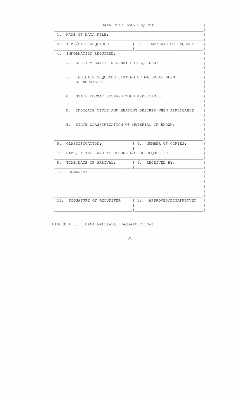
4.3 Query Preparation. All requests for information retrieval system output will be prepared on the form shown in Figure 4-01 in accordance with the instructions contained in Figure 4-02. Paragraph 4.5 contains sample information retrieval system outputs and explanations of the use of this data.
a. Headquarters Marine Corps HMSS users submit the data retrieval request (Figure 4-01) or the request and a MARK IV program(s) to the Commandant of the Marine Corps (Code LMM) for transmittal to the Commanding General (Code 730), MCLSBLant.
b. MCLSBLant HMSS users will submit the data retrieval request in accordance with local procedures to the Commanding General (Code 730), MCLSBLant.
4.4 Control Instructions.
a. The external information retrieval system for the MIMMS AIS/HMSS is controlled by the Commanding General, MCLSBLant. Specific instructions are contained in the operations manual; and any questions regarding data extraction should be addressed to the Commanding General (Code 730), MCLSBLant, via the Commandant of the Marine Corps (Code LMM).
34
_________________________________________________________________ | DATA RETRIEVAL REQUEST | |_______________________________________________________________| | 1. NAME OF DATA FILE: | |_______________________________________________________________| | 2. TIME/DATE REQUIRED: | 3. TIME/DATE OF REQUEST: | |_________________________________|_____________________________| | 4. INFORMATION REQUIRED: | | | | A. SPECIFY EXACT INFORMATION REQUIRED: | | | | | | B. INDICATE SEQUENCE LISTING OF MATERIAL WHEN | | APPROPRIATE: | | | | | | C. STATE FORMAT DESIRED WHEN APPLICABLE: | | | | | | D. INDICATE TITLE AND HEADING DESIRED WHEN APPLICABLE: | | | | | | E. STATE CLASSIFICATION OF MATERIAL IF KNOWN: | | | | | |_______________________________________________________________| | 5. CLASSIFICATION: | 6. NUMBER OF COPIES: | |_________________________________|_____________________________| | 7. NAME, TITLE, AND TELEPHONE NO. OF REQUESTER: | |_______________________________________________________________| | 8. TIME/DATE OF ARRIVAL: | 9. RECEIVED BY: | |_________________________________|_____________________________| | 10. REMARKS: | | | | | | | | | |_______________________________________________________________| | 11. SIGNATURE OF REQUESTER | 12. APPROVED/DISAPPROVED | | | | |_________________________________|_____________________________|
FIGURE 4-01. Data Retrieval Request Format
35

_______________________________________________________________
1. Name of Data File. Exact title of file.
2. Time/Date Required. Self-explanatory.
3. Time/Date of Request. Self-explanatory.
4. Information Required
a. Specify Exact Information Required. Indicate the exact data necessary to meet your requirements.
b. Indicate Sequence Listing of Material When Desired. If a specific sequence is desired, indicate accordingly; i.e., listing by TAMCN, ID, and nomenclature.
c. State Format Desired When Applicable. Indicate desired arrangement; i.e., five spaces between ID and nomenclature, etc.
d. Indicate Title and Heading Desired When Applicable. Self-explanatory.
e. State Classification of Material if Known. Self-explanatory.
5. Classification. Leave blank.
6. Number of Copies. Indicate number of copies required.
7. Name, Title, and Telephone Number of Requester. Self-explanatory.
8. Time/Date of Arrival. Leave blank.
9. Received By. Leave blank.
10. Remarks. Indicate any additional information which will further clarify staff needs.
11. Signature of Requester. Self-explanatory.
12. Approved/Disapproved. The director of the ASC will line out the word not applicable and sign. If disapproved, the request will be returned to the requester with an explanation.
_______________________________________________________________
FIGURE 4-02. Data Retrieval Request Instructions
36

b. Prior to programming a report extraction, the HMSS user should be familiar with the appropriate file definitions contained in Appendix P and the data elements definitions contained in Appendix C. The definitions will provide for the specified data base files the proper name, size, location, and formats of the fields, file keys, record structure, and any additional information required to manipulate the file and its data elements.
4.5 Sample Information Retrieval System Outputs. This paragraph contains sample information retrieval system outputs which could be extracted from the HMSS data base. These outputs support some of the common maintenance management functions performed by HMSS users. The functions are:
a. Equipment reliability and maintainability analysis.
b. Equipment failure analysis.
c. Repair part application analysis.
d. Maintenance task analysis.
4.5.1 Equipment Reliability and Maintainability Analysis.
a. The primary means of improving equipment availability is to increase its reliability and/or maintainability. Reliability is increased by redesigning or rebuilding the equipment. Maintainability is increased by decreasing the maintenance time required to repair the equipment.
b. Figure 4-03 is a sample output for equipment reliability. The heading includes standards data of the equipment, in this case a generator. Reliability and maintainability functions are related to the age of the equipment being analyzed; thus, the sample reports categorize equipments into "use group" intervals, representing the age of equipments as a function of their operating time (equipment operating time (EOT)). The requester would have identified the equipment type to be analyzed on his/her request by submitting one or more of the following data elements:
(1) ID number
37

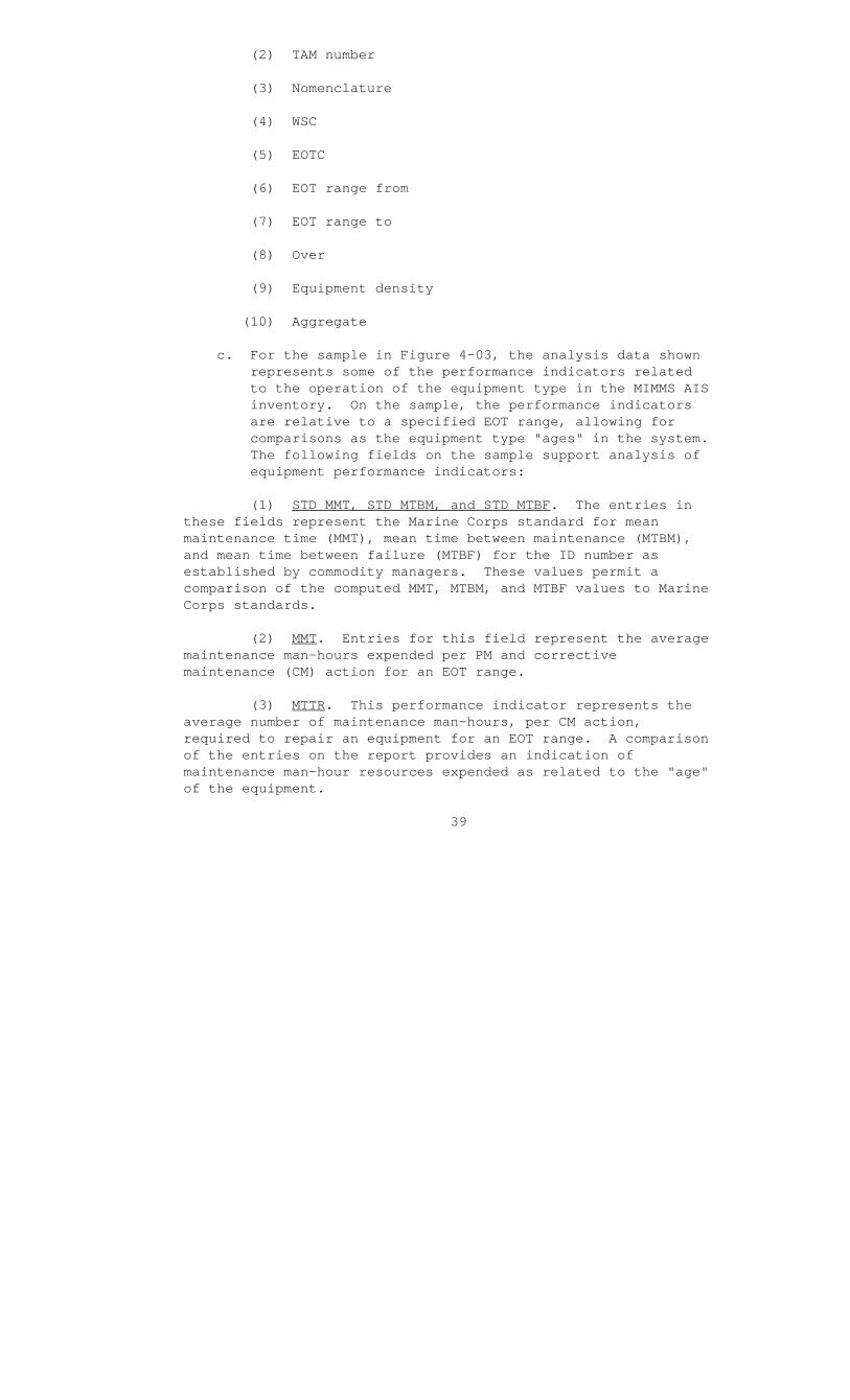
(2) TAM number
(3) Nomenclature
(4) WSC
(5) EOTC
(6) EOT range from
(7) EOT range to
(8) Over
(9) Equipment density
(10) Aggregate
c. For the sample in Figure 4-03, the analysis data shown represents some of the performance indicators related to the operation of the equipment type in the MIMMS AIS inventory. On the sample, the performance indicators are relative to a specified EOT range, allowing for comparisons as the equipment type "ages" in the system. The following fields on the sample support analysis of equipment performance indicators:
(1) STD MMT, STD MTBM, and STD MTBF. The entries in these fields represent the Marine Corps standard for mean maintenance time (MMT), mean time between maintenance (MTBM), and mean time between failure (MTBF) for the ID number as established by commodity managers. These values permit a comparison of the computed MMT, MTBM, and MTBF values to Marine Corps standards.
(2) MMT. Entries for this field represent the average maintenance man-hours expended per PM and corrective maintenance (CM) action for an EOT range.
(3) MTTR. This performance indicator represents the average number of maintenance man-hours, per CM action, required to repair an equipment for an EOT range. A comparison of the entries on the report provides an indication of maintenance man-hour resources expended as related to the "age" of the equipment.
39

(4) MTBM. This performance indicator permits the HMSS requester to compare equipment availability to the "age" of the equipment. Maintenance actions include PM as well as CM.
(5) MTBF. The MTBM entries are an indication of equipment availability, and the MTBM entries are an indication of the equipment operational availability.
(6) Average MMT, MTTR, MTBM, and MTBF. The averages of the respective performance indicators represent performance indicators which have applicability for the total EOT range. The average entries can be used to make comparisons between individual EOT range entries and the Marine Corps standard entries.
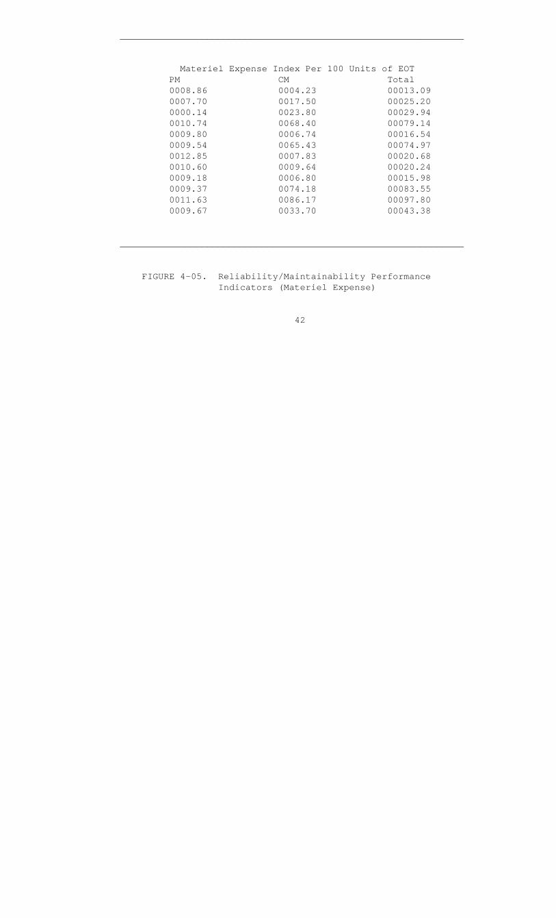
d. The sample shown in Figure 4-03 provides performance indicators in terms of maintenance times; other indicators could be man-hours or materiel expense. Figure 4-04 depicts a set of man-hours indicators which could have been substituted for the maintenance time indicators shown in Figure 4-03. Figure 4-05 contains a set of materiel expense indicators which also could have been selected instead of the maintenance times for analysis.
4.5.2 Equipment Failure Analysis. The equipment reliability and maintainability outputs described in paragraph 4.5.1 provide a general indication of possible problem areas associated with an equipment type. Equipment failure analysis is normally performed to obtain a more detailed view of a potential problem area detected through reliability and maintainability analysis. For example, when the failure rate or MTBF of an equipment type exceeds the standards established by Headquarters Marine Corps, then equipment failure analysis would be in order. Figures 4-06 and 4-07 depict output requested to permit equipment failure analysis.
40

_______________________________________________________________
Man-Hour Index Per 100 Units of EOT PM CM Total 0001.5 0001.0 00002.5 0001.0 0001.0 00002.0 0001.4 0001.6 00003.0 0001.0 0001.3 00002.3 0001.1 0001.1 00002.2 0001.7 0001.7 00003.4 0001.0 0001.3 00002.3 0001.2 0001.4 00002.6 0001.1 0001.6 00002.7 0001.0 0001.3 00002.3 0001.5 0001.6 00003.1 0001.2 0001.4 00003.1
______________________________________________________________
FIGURE 4-04. Reliability/Maintainability Performance Indicators (Man-Hours)
41
_______________________________________________________________
Materiel Expense Index Per 100 Units of EOT PM CM Total 0008.86 0004.23 00013.09 0007.70 0017.50 00025.20 0000.14 0023.80 00029.94 0010.74 0068.40 00079.14 0009.80 0006.74 00016.54 0009.54 0065.43 00074.97 0012.85 0007.83 00020.68 0010.60 0009.64 00020.24 0009.18 0006.80 00015.98 0009.37 0074.18 00083.55 0011.63 0086.17 00097.80 0009.67 0033.70 00043.38
_______________________________________________________________
FIGURE 4-05. Reliability/Maintainability Performance Indicators (Materiel Expense)
42


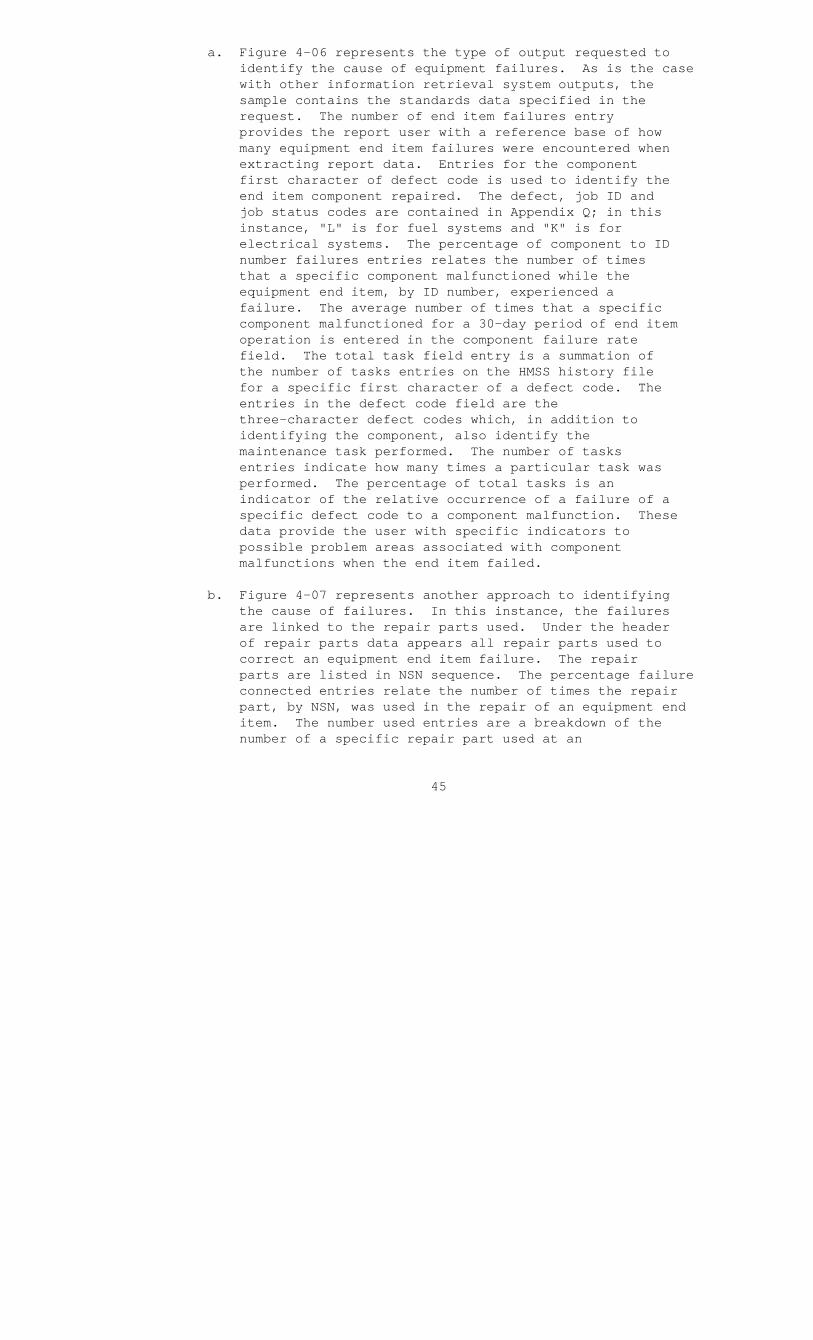
a. Figure 4-06 represents the type of output requested to identify the cause of equipment failures. As is the case with other information retrieval system outputs, the sample contains the standards data specified in the request. The number of end item failures entry provides the report user with a reference base of how many equipment end item failures were encountered when extracting report data. Entries for the component first character of defect code is used to identify the end item component repaired. The defect, job ID and job status codes are contained in Appendix Q; in this instance, "L" is for fuel systems and "K" is for electrical systems. The percentage of component to ID number failures entries relates the number of times that a specific component malfunctioned while the equipment end item, by ID number, experienced a failure. The average number of times that a specific component malfunctioned for a 30-day period of end item operation is entered in the component failure rate field. The total task field entry is a summation of the number of tasks entries on the HMSS history file for a specific first character of a defect code. The entries in the defect code field are the three-character defect codes which, in addition to identifying the component, also identify the maintenance task performed. The number of tasks entries indicate how many times a particular task was performed. The percentage of total tasks is an indicator of the relative occurrence of a failure of a specific defect code to a component malfunction. These data provide the user with specific indicators to possible problem areas associated with component malfunctions when the end item failed.
b. Figure 4-07 represents another approach to identifying the cause of failures. In this instance, the failures are linked to the repair parts used. Under the header of repair parts data appears all repair parts used to correct an equipment end item failure. The repair parts are listed in NSN sequence. The percentage failure connected entries relate the number of times the repair part, by NSN, was used in the repair of an equipment end item. The number used entries are a breakdown of the number of a specific repair part used at an
45

echelon of maintenance. The average number per use represents the average number of a particular repair part required per maintenance action related to an end item failure. The failure rate entries represent usage data for a 30-day period, while the consumption rate represents usage per 100 units of EOT. The sample provides the user with indicators of possible problems associated with excessive usage of a specific repair part in repair of a specific end item which failed.
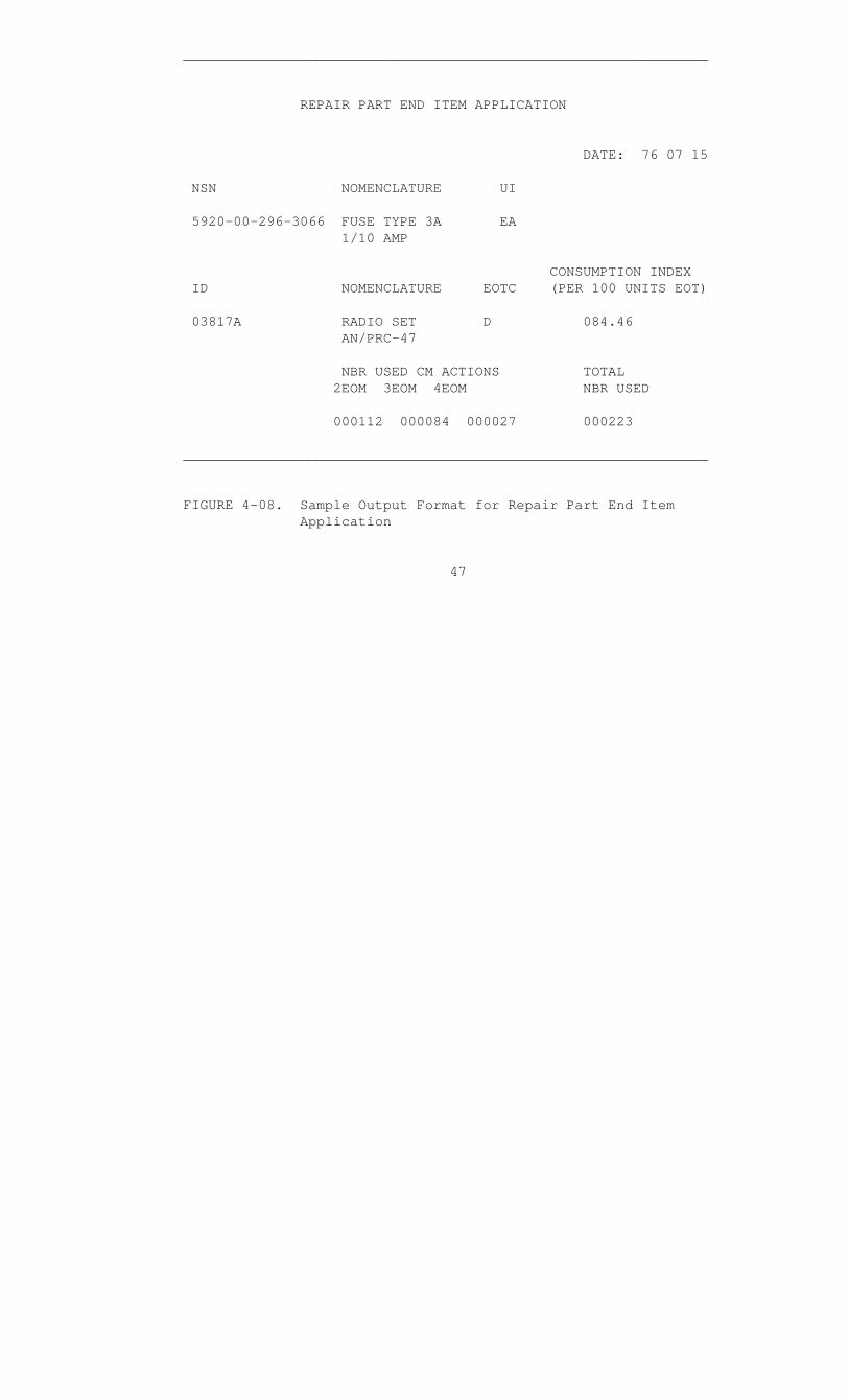
4.5.3 Repair Part Application. The samples shown in Figures 4-08 and 4-09 are examples of information retrieval output which can be extracted. Repair part consumption can be related to end items (Figure 4-08) or secondary reparables (Figure 4-09). The requester specifies the NSN of the repair part to be analyzed. The NSN is used as a key to access records resident in the HMSS history file. The repair part analysis data shown is only a sample of what is available. The request could have included the number used for PM actions or for modification (MOD) actions. The explanation of the samples provided applies to both Figures 4-08 and 4-09.
a. Number Used for CM Actions at Second Through Fourth Echelons of Maintenance (EOM’s). Entries in these fields provide a breakdown of the quantity of repair parts used at the specified EOM to repair an item which required CM. The materiel usage code indicates the maintenance action for which the repair part was required (CM, PM, or MOD). Since the sample did not specify a timeframe for which application data was to be extracted, the complete HMSS history file was searched for occurrences of the repair part NSN.
b. Total Number Used. The entry in this field is a summation of the entries for the quantity of a specific repair part used for CM actions at second through fourth EOM’s per ID number or secondary reparable NSN.
4.5.4 Maintenance Task Analysis. The sample shown in Figure 4-10 contains data which indicates the overall effort required to maintain an equipment. The sample provides summary data, by EOM for a requested ID number, which can be used to analyze the maintainability of the equipment type.
46
_______________________________________________________________
REPAIR PART END ITEM APPLICATION
DATE: 76 07 15
NSN NOMENCLATURE UI
5920-00-296-3066 FUSE TYPE 3A EA 1/10 AMP
CONSUMPTION INDEX ID NOMENCLATURE EOTC (PER 100 UNITS EOT)
03817A RADIO SET D 084.46 AN/PRC-47
NBR USED CM ACTIONS TOTAL 2EOM 3EOM 4EOM NBR USED
000112 000084 000027 000223
_______________________________________________________________
FIGURE 4-08. Sample Output Format for Repair Part End Item Application
47

_______________________________________________________________
REPAIR PART SECONDARY REPARABLE APPLICATION
NSN NOMENCLATURE UI
5920-00-296-3066 FUSE TYPE 3AG EA 1/10 AMP
AVERAGE USED SEC REP NSN SEC REP NOMENCLATURE PER SEC REP
5920-00-082-1599 RECEIVER-TRANSMITTER 00.20 PT-671/PRC-47
NBR USED CM ACTIONS TOTAL 2EOM 3EOM 4EOM NBR USED
000000 000000 000011 000011
_______________________________________________________________
FIGURE 4-09. Sample Output Format for Repair Part Secondary Reparable Application
48
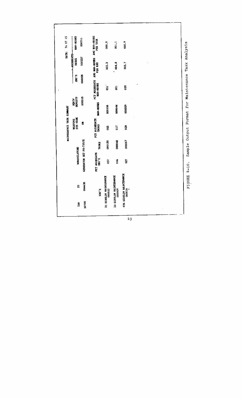

a. Equipment Identification Data. The requester specifies equipment identification data which consists of ID number, TAM number, nomenclature, and WSC. The equipment density field was added to provide the requester with the quantity of the equipment type in the MIMMS AIS inventory.
b. Maintenance Task Analysis Data. The remainder of the output information on the sample is analysis data related to the performance of maintenance actions. The fields are as follows:
(1) Aggregate ERO’s. The entry in this field indicates the total number of ERO’s opened and closed at second through fourth EOM activities referencing the specified ID number.
(2) Aggregate Tasks. The entry in this field is a summation of the number of maintenance tasks performed on the specified ID number as extracted from the number of tasks field entries for completed ERO’s.
(3) Aggregate Man-Hours. The entry in this field is a summation of the number of maintenance man-hours expended for ERO’s included in the aggregate ERO’s count. Data for this field is extracted from the military labor hours field entry related to the completed ERO’s.
(4) Remaining Fields. For the remainder of the sample, the aggregate entries are subdivided into the EOM at which they occurred. Percentages of the aggregate entries are provided for comparison between EOM’s. The average man-hours expended per ERO and per task provide the user with further maintainability indicators which can be used to evaluate workloads related to an EOM and the ID number.
4.5.5 Summary. The preceding paragraphs have specified the procedure for submitting a query to the external information retrieval system and samples of system output. The significant advantage to an external information retrieval system is that the user is not limited to output reports developed by the systems designer. However, the user must familiarize himself/herself with the data elements available in the data base and decide which will best provide the necessary management information.
50

APPENDIX A
SAMPLE INPUT TRANSACTIONS AND LEGENDS FOR THE HMSS
"01" Transaction . . . . . . . . . . . . . . . . A-2
"02" Transaction . . . . . . . . . . . . . . . . A-4
"03" Transaction . . . . . . . . . . . . . . . . A-6
"04" Transaction . . . . . . . . . . . . . . . . A-7
"05" Transaction . . . . . . . . . . . . . . . . A-8
"06" Transaction . . . . . . . . . . . . . . . . A-9
"11" Transaction . . . . . . . . . . . . . . . . A-10
"15" Transaction . . . . . . . . . . . . . . . . A-11
"16" Transaction . . . . . . . . . . . . . . . . A-12
"17" Transaction . . . . . . . . . . . . . . . . A-13
"DE1" Transaction . . . . . . . . . . . . . . . A-14
"DF2" Transaction . . . . . . . . . . . . . . . A-15
"JBS" Transaction . . . . . . . . . . . . . . . A-16
"JI1" Transaction . . . . . . . . . . . . . . . A-17
"JI2" Transaction . . . . . . . . . . . . . . . A-18
Unit Data Transaction . . . . . . . . . . . . . . A-19
TAM Data Transaction . . . . . . . . . . . . . . A-20
A-1
LEGEND Card Key Column Title Explanation
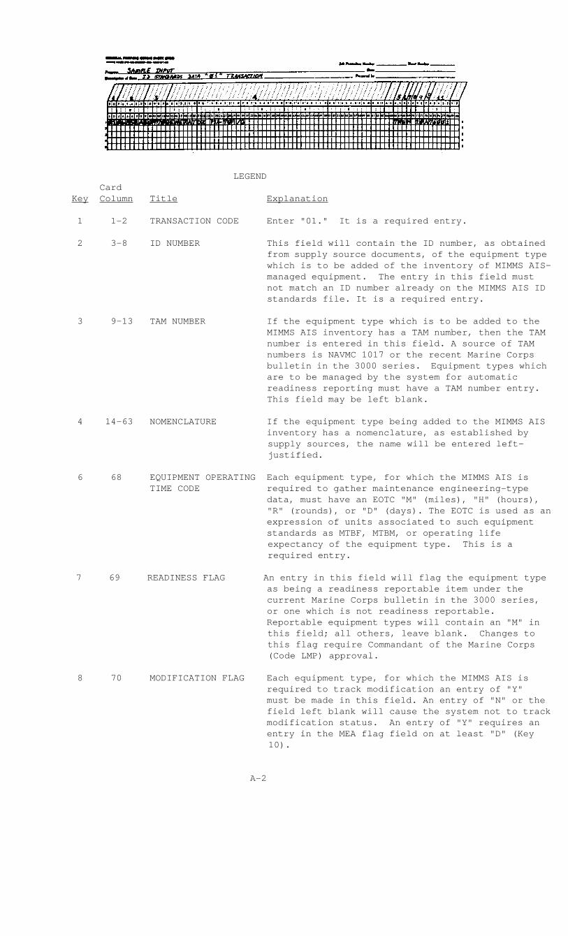
1 1-2 TRANSACTION CODE Enter "01." It is a required entry.
2 3-8 ID NUMBER This field will contain the ID number, as obtained from supply source documents, of the equipment type which is to be added of the inventory of MIMMS AIS-managed equipment. The entry in this field must not match an ID number already on the MIMMS AIS ID standards file. It is a required entry.
3 9-13 TAM NUMBER If the equipment type which is to be added to the MIMMS AIS inventory has a TAM number, then the TAM number is entered in this field. A source of TAM numbers is NAVMC 1017 or the recent Marine Corps bulletin in the 3000 series. Equipment types which are to be managed by the system for automatic readiness reporting must have a TAM number entry. This field may be left blank.
4 14-63 NOMENCLATURE If the equipment type being added to the MIMMS AIS inventory has a nomenclature, as established by
supply sources, the name will be entered left-justified.
6 68 EQUIPMENT OPERATING Each equipment type, for which the MIMMS AIS is TIME CODE required to gather maintenance engineering-type data, must have an EOTC "M" (miles), "H" (hours),
"R" (rounds), or "D" (days). The EOTC is used as an expression of units associated to such equipment standards as MTBF, MTBM, or operating life
expectancy of the equipment type. This is a required entry.
7 69 READINESS FLAG An entry in this field will flag the equipment type as being a readiness reportable item under the current Marine Corps bulletin in the 3000 series, or one which is not readiness reportable.
Reportable equipment types will contain an "M" in this field; all others, leave blank. Changes to this flag require Commandant of the Marine Corps (Code LMP) approval.
8 70 MODIFICATION FLAG Each equipment type, for which the MIMMS AIS is required to track modification an entry of "Y" must be made in this field. An entry of "N" or the field left blank will cause the system not to track modification status. An entry of "Y" requires an entry in the MEA flag field on at least "D" (Key
10).
A-2
Card Key Column Title Explanation
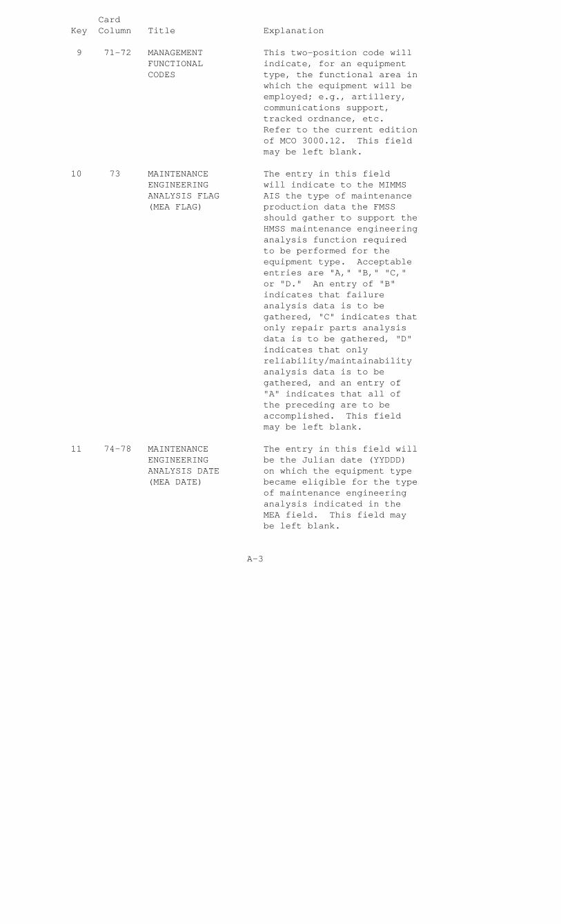
9 71-72 MANAGEMENT This two-position code will FUNCTIONAL indicate, for an equipment CODES type, the functional area in which the equipment will be employed; e.g., artillery, communications support, tracked ordnance, etc. Refer to the current edition of MCO 3000.12. This field may be left blank.
10 73 MAINTENANCE The entry in this field ENGINEERING will indicate to the MIMMS ANALYSIS FLAG AIS the type of maintenance (MEA FLAG) production data the FMSS should gather to support the HMSS maintenance engineering analysis function required to be performed for the equipment type. Acceptable entries are "A," "B," "C," or "D." An entry of "B" indicates that failure analysis data is to be gathered, "C" indicates that only repair parts analysis data is to be gathered, "D" indicates that only reliability/maintainability analysis data is to be gathered, and an entry of "A" indicates that all of the preceding are to be accomplished. This field may be left blank.
11 74-78 MAINTENANCE The entry in this field will ENGINEERING be the Julian date (YYDDD) ANALYSIS DATE on which the equipment type (MEA DATE) became eligible for the type of maintenance engineering analysis indicated in the MEA field. This field may be left blank.
A-3
LEGEND
Card Key Column Title Explanation
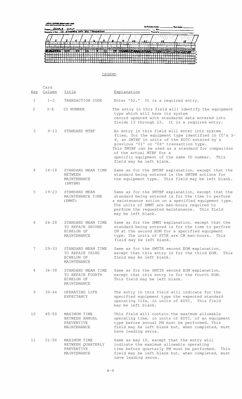
1 1-2 TRANSACTION CODE Enter "02." It is a required entry.
2 3-8 ID NUMBER The entry in this field will identify the equipment type which will have its system
record updated with standards data entered into fields 13 through 23. It is a required entry.
3 9-13 STANDARD MTBF An entry in this field will enter into system files, for the equipment type identified in CC’s 3-8, an SMTBF in units of the EOTC entered by a previous "01" or "04" transaction type.
This SMTBF can be used as a standard for comparison of the actual MTBF for a
specific equipment of the same ID number. This field may be left blank.
4 14-18 STANDARD MEAN TIME Same as for the SMTBF explanation, except that the BETWEEN standard being entered is the SMTBM actions for MAINTENANCE the equipment type. This field may be left blank. (SMTBM)
5 19-23 STANDARD MEAN Same as for the SMTBF explanation, except that the MAINTENANCE TIME standard being entered is for the time to perform (SMMT) a maintenance action on a specified equipment type.
The units of SMMT are man-hours required to perform the requested maintenance. This field may be left blank.
6 24-28 STANDARD MEAN TIME Same as for the SMMT explanation, except that the TO REPAIR SECOND standard being entered is for the time to perform ECHELON OF CM at the second EOM for a specified equipment MAINTENANCE type. The units of STTR are CM man-hours. This
field may be left blank.
7 29-33 STANDARD MEAN TIME Same as for the SMTTR second EOM explanation, TO REPAIR THIRD except that this entry is for the third EOM. This ECHELON OF field may be left blank. MAINTENANCE 8 34-38 STANDARD MEAN TIME Same as for the SMTTR second EOM explanation, TO REPAIR FOURTH except that this entry is for the fourth EOM. ECHELON OF This field may be left blank. MAINTENANCE
9 39-44 OPERATING LIFE The entry in this field will indicate for the EXPECTANCY specified equipment type the expected standard
operating life, in units of EOTC. This field may be left blank.
10 45-50 MAXIMUM TIME This field will contain the maximum allowable BETWEEN ANNUAL operating time, in units of EOTC, of an equipment PREVENTIVE type before annual PM must be performed. This MAINTENANCE field may be left blank but, when completed, must
have leading zeros.
11 51-56 MAXIMUM TIME Same as key 10, except that the entry will BETWEEN QUARTERLY indicate the maximum allowable operating PREVENTIVE time before quarterly PM must be performed. This MAINTENANCE field may be left blank but, when completed, must
have leading zeros.
A-4

Card Key Column Title Explanation
12 57-69 NSN This field, when present, will identify the NSN associated with the equipment type identified in the ID field. The entry is obtained from supply sources. An entry is required on the initial "02" transaction.
13 70-78 STANDARD UNIT PRICE This field will contain the standard unit price (SUP) of the equipment type identified in the ID field. The SUP is obtained from supply sources but, when completed, must have leading zeros.
A-5

LEGEND
Card Key Column Title Explanation
1 1-2 TRANSACTION CODE Enter "03." It is a required entry.
2 3-8 ID NUMBER Enter the ID number of an equipment type in the MIMMS AIS inventory which is to be deleted. It is a required entry.
A-6

LEGEND
Card Key Column Title Explanation
1 1-2 TRANSACTION CODE Enter "04." It is a required entry.
2 3-8 ID NUMBER The ID number entered in this field will identify the equipment type, in the MIMMS AIS inventory, whose ID standards file record is to be updated with a "04"transaction type. It is a required entry.
3 9-13 TAM NUMBER An entry in this field will overlay a TAM number entry in the ID standards file record for this equipment type. This field may be left blank.
4 44-56 NSN An entry in this field will overlay the NSN field in the ID standards file for this equipment. This field may be left blank.
5 57-65 ACQUISITION COST An entry in this field will overlay the acquisition cost field in the ID standards file for this equipment. This field may be left blank but, when completed, must have leading zeros.
6 66-67 WEAPONS SYSTEM CODE An entry in this field will overlay the WSC field in the ID standards file for this equipment. This field may be left blank.
7 68 EQUIPMENT OPERATING An entry in this field will overlay the EOTC field TIME CODE in the ID standards file for this equipment. This
field may be left blank.
8 69 READINESS FLAG An entry in this field will overlay the readiness flag field in the ID standards file for this equipment. This field may be left blank.
9 70 MODIFICATION FLAG An entry in this field will overlay the modification control flag field in the ID
standards file for this equipment. This field may be left blank.
10 71-72 MANAGEMENT An entry in this field will overlay the management FUNCTIONAL functional code field in the ID standards file for CODES this equipment. This field may be left blank.
11 73 MAINTENANCE An entry in this field will overlay the MEA flag ENGINEERING field in the ID standards file for this equipment. ANALYSIS FLAG This field may be left blank.
12 74-78 MAINTENANCE An entry in this field will overlay the MEA date ENGINEERING field in the ID standards file for this equipment. ANALYSIS DATE This field may be left blank (YYDDD). (MEA DATE)
A-7

LEGEND
Card Key Column Title Explanation
1 1-2 TRANSACTION CODE Enter "05." It is a required entry.
2 3-8 ID NUMBER Enter the ID number field which identifies the specific equipment type record in the ID standards file which is to be updated. It is a required entry.
3 9-21 NSN An entry in this field will overlay the data in the ID standards file for the NSN of this equipment type. This field may be left blank.
4 22-30 ACQUISITION COST An entry in this field will overlay the acquisition cost field in the ID standards file. This field may be left blank but, when completed, must have leading zeros.
5 31-80 NOMENCLATURE An entry in this field will overlay the nomenclature field in the ID standards file. This field may be left blank.
A-8
LEGEND
Card
Key Column Title Explanation
1 1-2 TRANSACTION CODE Enter "06." It is a required entry.
2 3-8 ID NUMBER Enter the ID number in this field which identifies the specific equipment type record in the ID standards file which is to be updated. It is a required entry.
3 9-11 AFFECTED FIELD An entry in this field will contain one of the following codes: WSC, MEA, MAR, FUN, or MOD which will respectively blank out the weapons systems code, maintenance engineering analysis flag, readiness flag, management functional code fields, and modification control flag. It is a required entry. An entry of MEA will also blank out the MEA date entry.
A-9
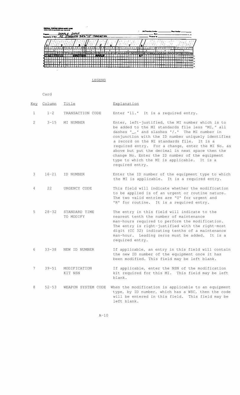
LEGEND
Card
Key Column Title Explanation
1 1-2 TRANSACTION CODE Enter "11." It is a required entry.
2 3-15 MI NUMBER Enter, left-justified, the MI number which is to be added to the MI standards file less "MI," all dashes "_," and slashes "/." The MI number in
conjunction with the ID number uniquely identifies a record on the MI standards file. It is a required entry. For a change, enter the MI No. as
above but put the decimal in next space then the change No. Enter the ID number of the equipment type to which the MI is applicable. It is a
required entry.
3 16-21 ID NUMBER Enter the ID number of the equipment type to which the MI is applicable. It is a required entry.
4 22 URGENCY CODE This field will indicate whether the modification to be applied is of an urgent or routine nature. The two valid entries are "U" for urgent and
"R" for routine. It is a required entry.
5 28-32 STANDARD TIME The entry in this field will indicate to the TO MODIFY nearest tenth the number of maintenance man-hours required to perform the modification.
The entry is right-justified with the right-most digit (CC 32) indicating tenths of a maintenance man-hour. Leading zeros must be added. It is a
required entry.
6 33-38 NEW ID NUMBER If applicable, an entry in this field will contain the new ID number of the equipment once it has been modified. This field may be left blank.
7 39-51 MODIFICATION If applicable, enter the NSN of the modification KIT NSN kit required for this MI. This field may be left
blank.
8 52-53 WEAPON SYSTEM CODE When the modification is applicable to an equipment type, by ID number, which has a WSC, then the code
will be entered in this field. This field may be left blank.
A-10

LEGEND
Card
Key Column Title Explanation
1 1-2 TRANSACTION CODE Enter "15.". It is a required entry.
2 3-15 MI NUMBER Enter, left-justified, the MI number less "MI," all dashes "_," and all slashes "/." It is a required entry. Entry on this card must be identical to the "11" card for this field.
3 16-21 ID NUMBER Enter the ID number of the equipment type to which the MI is applicable. It is a required entry.
4 22-23 ACTION CODE The entry in this field will specify whether the "15" transaction type submission is an addition, charge, or deletion of an MI serial number range restriction. The applicable codes are "SA," "SC," and "SD." The serial number from and the serial number to fields are left blank only on the SD transaction.
5 24-25 TRAILER NUMBER The entry in this field will uniquely identify each trailer record associated with a prime MI record. Valid entries in this field are "01" to "99." It is a required entry.
6 31-50 SERIAL NUMBER FROM An entry is required in this field when the action code is either "SA" or "SC." The entry will be right-justified with the last 10 positions being numeric. The entry in this field must be numerically less than or equal to the entry in the serial number to field.
7 51-70 SERIAL NUMBER TO The entry in this field has the same criteria as the serial number from field, except that the entry must be numerically equal to or greater than the entry in the serial number from field.
A-11

LEGEND
Card
Key Column Title Explanation
1 1-2 TRANSACTION CODE Enter "16." It is a required entry.
2 3-15 MI NUMBER Enter, left-justified, the MI number less "MI," all dashes "_," and all slashes "/." It is a required entry. An entry in this field must be exactly the same as for the "11" and "15" cards.
3 16-21 ID NUMBER Enter the ID number of the equipment type to which the MI is applicable. It is a required entry.
4 22 URGENCY CODE An entry in this field will overlay a previous urgency code entry in the specified MI record of the MI standards file. Valid codes are "U" and "R." This field may be left blank.
5 28-32 STANDARD TIME An entry is made in this field TO MODIFY only when there is a correction or change to an MI standards file entry. The entry is right-justified with the last digit representing tenths of maintenance man-hours. This field may be left blank.
6 33-38 NEW ID NUMBER An entry in this field will overlay a previous new ID number entry in the MI standards file for the specified MI record. This field may be left blank.
7 39-51 MODIFICATION An entry in this field will overlay a previous NSN entry in the specified MI record of the MI standards file. This field may be left blank.
8 52-53 WEAPON SYSTEM An entry in this field will CODE overlay a previous WSC entry for a specified MI record in the MI standards file. This field may be left blank.
A-12

LEGEND
Card
Key Column Title Explanation
1 1-2 TRANSACTION CODE Enter "17." It is a required entry.
2 3-15 MI NUMBER Enter the MI number, left-justified, which is to be deleted from the MI standards file. An entry in this field must be exactly the same as the existing "11," "15," and "16" card entries.
3 16-21 ID NUMBER Enter the ID number of the equipment type to which the MI is applicable. It is a required entry.
A-13

LEGEND
Card
Key Column Title Explanation
1 1-3 TRANSACTION CODE Enter "DF1." It is a required entry.
2 4 FIRST CHARACTER Enter the first character of OF DEFECT CODE the defect code to be added to the edit standards file. It is a required entry.
3 5-8 ABBREVIATION FOR Enter the abbreviation, FIRST CHARACTER left-justified, of the first OF DEFECT CODE character of the defect code to be added to the edit standards file. It is a required entry.
A-14
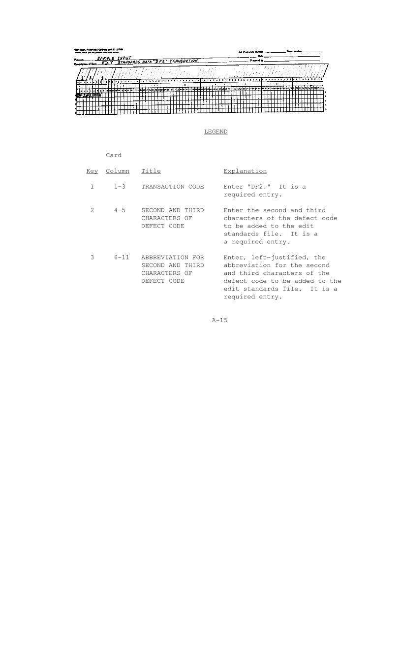
LEGEND
Card
Key Column Title Explanation
1 1-3 TRANSACTION CODE Enter "DF2." It is a required entry.
2 4-5 SECOND AND THIRD Enter the second and third CHARACTERS OF characters of the defect code DEFECT CODE to be added to the edit standards file. It is a a required entry.
3 6-11 ABBREVIATION FOR Enter, left-justified, the SECOND AND THIRD abbreviation for the second CHARACTERS OF and third characters of the DEFECT CODE defect code to be added to the edit standards file. It is a required entry.
A-15

LEGEND
Card
Key Column Title Explanation
1 1-3 TRANSACTION CODE Enter "JBS." It is a required entry.
2 4-5 JOB STATUS CODE Enter the two-position job status code which is to be added to the edit standards file. It is a required entry.
3 6-14 ABBREVIATION FOR Enter the abbreviation, JOB STATUS CODE left-justified, for the job status code which is to be added to the edit standards file. It is a required entry and may have spaces in any position but CC 6.
A-16

LEGEND
Key Column Title Explanation
1 1-3 TRANSACTION CODE Enter "JI1." It is a required entry.
2 4 FIRST CHARACTER OF Enter the first character of JOB IDENTIFICATION the job ID code which is to be CODE added to the edit standards file. It is a required entry.
3 5-7 ABBREVIATION FOR Enter the three-position FIRST CHARACTER OF abbreviation for the first JOB IDENTIFICATION character of the job ID code CODE which is to be added to the edit standards file. It is a required entry.
A-17

LEGEND
Code
Key Column Title Explanation
1 1-3 TRANSACTION CODE Enter "JI2." It is a required entry.
2 4 SECOND CHARACTER OF Enter the second character of JOB IDENTIFICATION the job ID code which is to be CODE added to the edit standards file. It is a required entry.
3 5 ABBREVIATION FOR Enter the abbreviation for the SECOND CHARACTER second character of the job ID OF JOB code which is to be added to IDENTIFICATION CODE the edit standards file. It is a required entry. Abbreviations for job ID codes already in use are contained in Appendix Q.
A-18
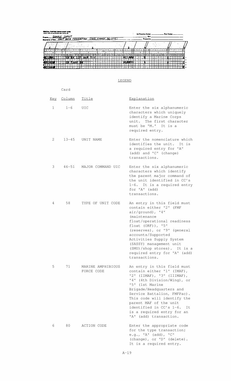
LEGEND
Card
Key Column Title Explanation
1 1-6 UIC Enter the six alphanumeric characters which uniquely identify a Marine Corps unit. The first character must be "M." It is a required entry.
2 13-45 UNIT NAME Enter the nomenclature which identifies the unit. It is a required entry for "A" (add) and "C" (change) transactions.
3 46-51 MAJOR COMMAND UIC Enter the six alphanumeric characters which identify the parent major command of the unit identified in CC’s 1-6. It is a required entry for "A" (add) transactions.
4 58 TYPE OF UNIT CODE An entry in this field must contain either "2" (FMF air/ground), "4" (maintenance float/operational readiness float (ORF)), "5" (reserves), or "9" (general accounts/Supported Activities Supply System (SASSY) management unit (SMU)/shop stores). It is a required entry for "A" (add) transactions.
5 71 MARINE AMPHIBIOUS An entry in this field must FORCE CODE contain either "1" (IMAF), "2" (IIMAF), "3" (IIIMAF), "4" (4th Division/Wing), or "5" (1st Marine Brigade/Headquarters and Service Battalion, FMFPac). This code will identify the parent MAF of the unit identified in CC’s 1-6. It is a required entry for an "A" (add) transaction.
6 80 ACTION CODE Enter the appropriate code for the type transaction; e.g., "A" (add), "C" (change), or "D" (delete). It is a required entry.
A-19
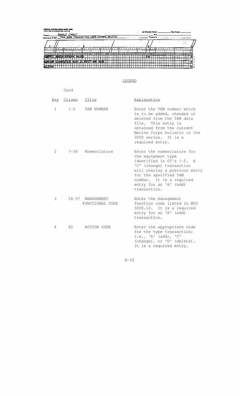
LEGEND
Card
Key Column Title Explanation
1 1-5 TAM NUMBER Enter the TAM number which is to be added, changed or deleted from the TAM data file. This entry is obtained from the current Marine Corps bulletin in the 3000 series. It is a required entry.
2 7-36 Nomenclature Enter the nomenclature for the equipment type identified in CC’s 1-5. A "C" (change) transaction will overlay a previous entry for the specified TAM number. It is a required entry for an "A" (add) transaction.
3 56-57 MANAGEMENT Enter the management FUNCTIONAL CODE function code listed in MCO 3000.12. It is a required entry for an "A" (add) transaction.
4 80 ACTION CODE Enter the appropriate code for the type transaction; i.e., "A" (add), "C" (change), or "D" (delete). It is a required entry.
A-20

APPENDIX B
SAMPLE OUTPUT REPORTS
Report Title Frequency Page
Edit Listing Upon B-2 Processing
ID Standards Data File Semiannually/ B-3 July January, As Requested
MI Standards Data File Semiannually/ B-4 July January, As Requested
Edit Standards Data File Semiannually/ B-5 July January, As Requested
Modification Status Report Quarterly B-6
Maintenance Manpower As Requested B-7 Utilization Report
Secondary Reparable Expense As Requested B-8 Equipment Status Exception As Requested B-9 Listing
Equipment Status Report As Requested B-10
UIC File As Requested B-11
TAMCN File As Requested B-12
B-1
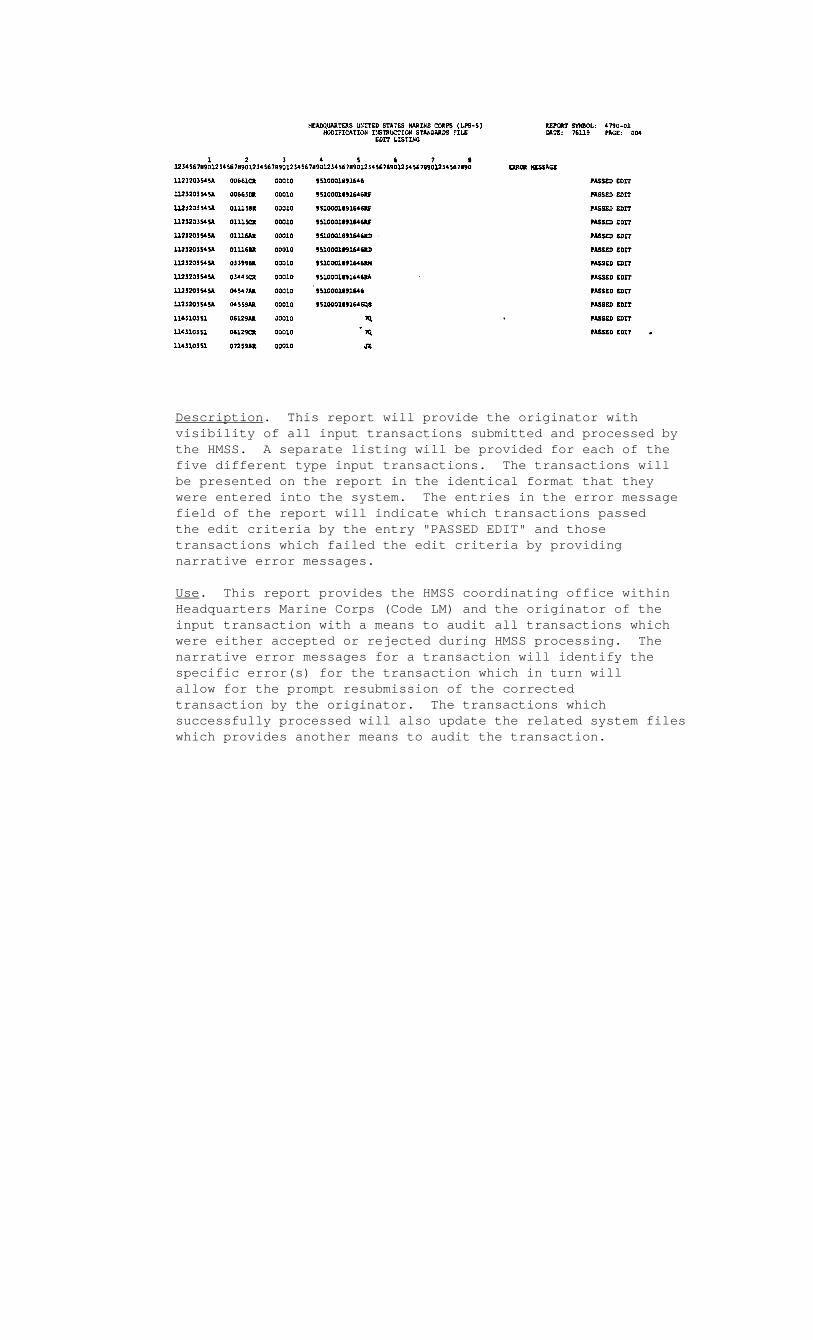
Description. This report will provide the originator with visibility of all input transactions submitted and processed by the HMSS. A separate listing will be provided for each of the five different type input transactions. The transactions will be presented on the report in the identical format that they were entered into the system. The entries in the error message field of the report will indicate which transactions passed the edit criteria by the entry "PASSED EDIT" and those transactions which failed the edit criteria by providing narrative error messages.
Use. This report provides the HMSS coordinating office within Headquarters Marine Corps (Code LM) and the originator of the input transaction with a means to audit all transactions which were either accepted or rejected during HMSS processing. The narrative error messages for a transaction will identify the specific error(s) for the transaction which in turn will allow for the prompt resubmission of the corrected transaction by the originator. The transactions which successfully processed will also update the related system files which provides another means to audit the transaction.


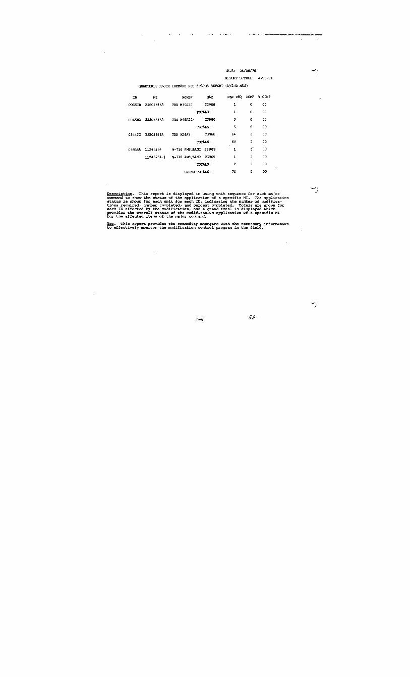
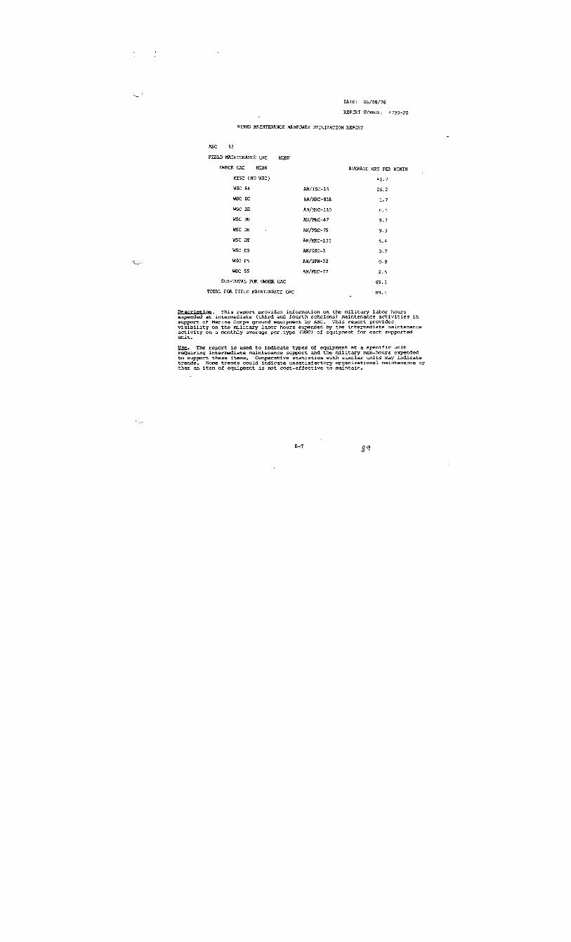
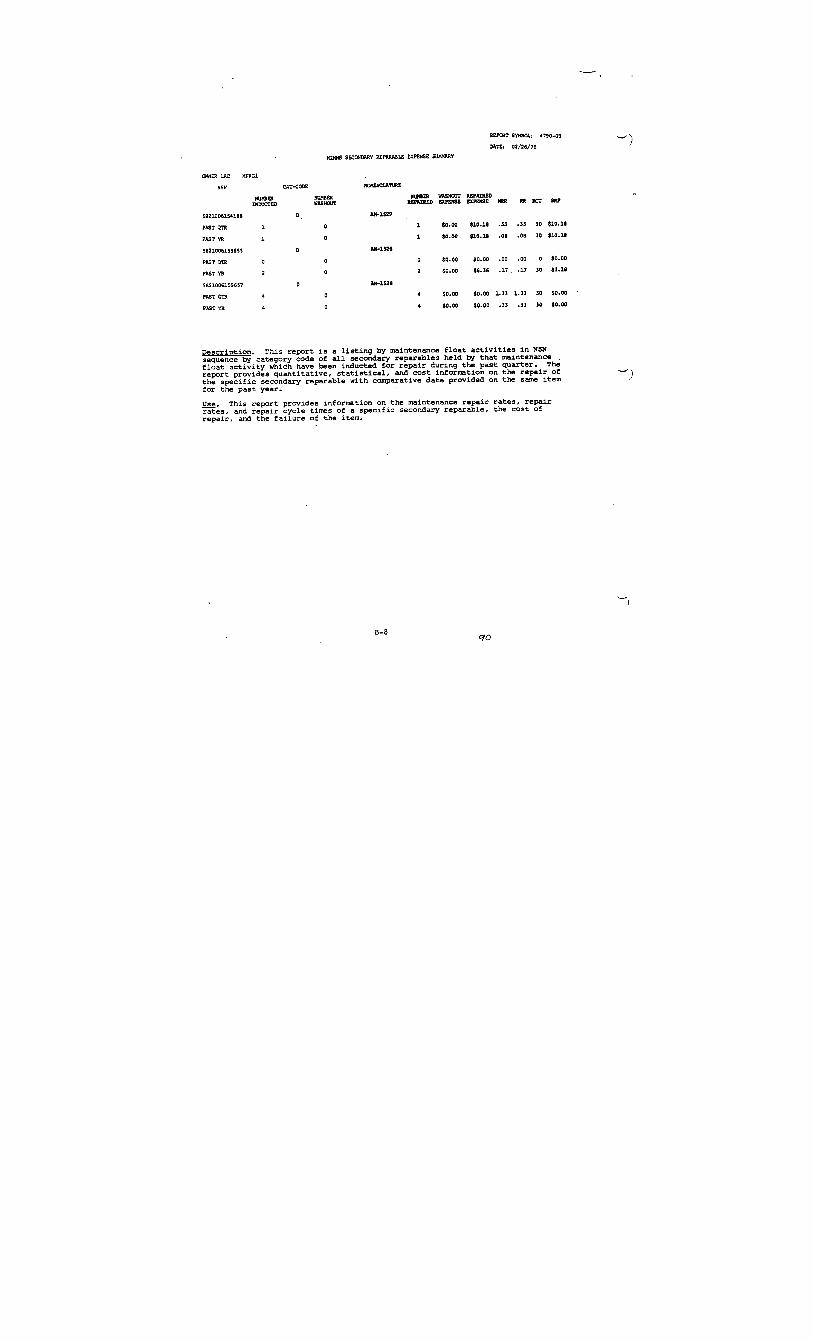


APPENDIX C


Appendix C
DATA ELEMENTS
This Appendix lists data elements appearing on HMSS input transactions which are resident in the HMSS data base and appearing on preformatted HMSS output reports. The format column contains the legal character combinations and length acceptable for system processing. The codes for the acceptable character types are "A" for an alphabetic character, "9" for a numeric character, "X" for an alphanumeric character, with special characters included where applicable. Prior to any MARK IV application, the HMSS user should refer to the HMSS file definition glossary contained in Appendix Q as well as the contents of this Appendix.
Data Element and Definition Label Format
STANDARD UNIT PRICE SUP 9,999,999.99
Definition. The standard unit price for one item of equipment type as obtained from supply sources. The storage format is a five-position packed field.
ACTION CODE ACT A or AA
Definition. The code is used to signal the type of HMSS data base action to be accomplished by the input. Valid codes for the unit data and TAM data transaction are "A" (add), "C" (change), and "D" (delete). Valid codes for the MI standards data "15" transaction type are "SA" (add), "SC" (change), or "SD" (delete).
ACTIVE RECORD FLAG ACTIVE-REC X
Definition. A one-character code used to indicate whether a specific record on the master equipment file is an active or inactive record. An active record is one where the item of equipment is in the MIMMS AIS inventory and maintenance engineering analysis data is being gathered.
C-1
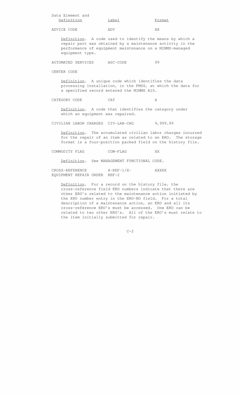
Data Element and Definition Label Format
ADVICE CODE ADV XX
Definition. A code used to identify the means by which a repair part was obtained by a maintenance activity in the performance of equipment maintenance on a MIMMS-managed equipment type.
AUTOMATED SERVICES ASC-CODE 99
CENTER CODE
Definition. A unique code which identifies the data processing installation, in the FMSS, at which the data for a specified record entered the MIMMS AIS.
CATEGORY CODE CAT A
Definition. A code that identifies the category under which an equipment was repaired.
CIVILIAN LABOR CHARGES CIV-LAB-CHG 9,999.99
Definition. The accumulated civilian labor charges incurred for the repair of an item as related to an ERO. The storage format is a four-position packed field on the history file.
COMMODITY FLAG COM-FLAG XX
Definition. See MANAGEMENT FUNCTIONAL CODE.
CROSS-REFERENCE X-REF-1/X- AXXXX EQUIPMENT REPAIR ORDER REF-2
Definition. For a record on the history file, the cross-reference field ERO numbers indicate that there are other ERO’s related to the maintenance action initiated by the ERO number entry in the ERO-NO field. For a total description of a maintenance action, an ERO and all its cross-reference ERO’s must be accessed. One ERO can be related to two other ERO’s. All of the ERO’s must relate to the item initially submitted for repair.
C-2
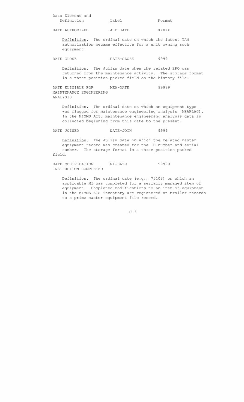
Data Element and Definition Label Format
DATE AUTHORIZED A-P-DATE XXXXX
Definition. The ordinal date on which the latest TAM authorization became effective for a unit owning such equipment.
DATE CLOSE DATE-CLOSE 9999
Definition. The Julian date when the related ERO was returned from the maintenance activity. The storage format is a three-position packed field on the history file.
DATE ELIGIBLE FOR MEA-DATE 99999 MAINTENANCE ENGINEERING ANALYSIS
Definition. The ordinal date on which an equipment type was flagged for maintenance engineering analysis (MEAFLAG). In the MIMMS AIS, maintenance engineering analysis data is collected beginning from this date to the present.
DATE JOINED DATE-JOIN 9999
Definition. The Julian date on which the related master equipment record was created for the ID number and serial number. The storage format is a three-position packed field.
DATE MODIFICATION MI-DATE 99999 INSTRUCTION COMPLETED
Definition. The ordinal date (e.g., 75103) on which an applicable MI was completed for a serially managed item of equipment. Completed modifications to an item of equipment in the MIMMS AIS inventory are registered on trailer records to a prime master equipment file record.
C-3

Data Element and Definition Label Format
DATE OF LAST DATE-LAST-PM 9999999 PREVENTIVE MAINTENANCE ACTION
Definition. The date on which the last preventive action was performed on a serially managed item of equipment. The storage format is a four-position packed field.
DATE POSSESSED A-P-DATE XXXXX
Definition. The latest ordinal date on which the number of equipments of a reportable TAM number possessed by a unit was reported to the system.
DATE RECEIVED DATE-RCVD 9999
Definition. The Julian date on which a repair part was received for an ERO in a maintenance activity. The storage format is a three-position packed field in the history file.
DATE RECEIVED IN SHOP DRIS 9999
Definition. The Julian date that the equipment, on which the ERO was opened, was received in a maintenance shop for repair. The storage format is a three-position packed field on the history file.
DATE RECORD ESTABLISHED DATE-REC-EST 99999
Definition. The ordinal date on which the specific record in the data base was created.
DATE RECORD LAST DATE-LAST-UPD 99999 UPDATED
Definition. The ordinal date on which the specific data base record was last updated.
DATE REPORT EXTRACTION DATE XXXXXX
Definition. The year, month, and day of the month on which HMSS report data was extracted from FMSS files.
C-4

Data Element and Definition Label Format
DATE T/E AUTHORIZATION TE-DATE XXXXX
Definition. The ordinal date on which the latest table of equipment (T/E) authorization of a TAM number became effective for an owning unit.
DEADLINE CONTROL DATE DCD 9999
Definition. The Julian date on which an equipment, submitted for repair on the ERO, was deadlined. The storage format is a three-position packed field on the history file.
DEADLINED EQUIPMENT DE-LABEL XXXXX LABEL
Definition. This entry will indicate whether an equipment is deadlined for administrative reasons or for an equipment failure. The two acceptable entries, respectively, are "ADMIN" and "TAMCN."
DEFECT CODE DEF-CDE X99
Definition. A three-character code used to relate a maintenance action performed to an equipment which was repaired. The first position will identify the subsystem of an equipment being repaired, and the last two digits will list the component within the subsystem which is being repaired. A listing of these codes is presented in Appendix Q.
DELETE DATE DEL-DATE or XXXXX DEL-DTE
Definition. The ordinal date on which an equipment asset was deleted from a unit’s inventory of readiness reportable equipments or when an equipment was removed from a deadline status.
DEPLOYMENT DEP-ID X IDENTIFICATION CODE
Definition. A one-character code specifying that an equipment is in deployed status.
C-5

Data Element and Definition Label Format
ECHELON OF MAINTENANCE EOM 9
Definition. A code used to indicate the EOM activity which performed the requested equipment maintenance.
EQUIPMENT OPERATING EOTC A TIME CODE
Definition. A one-character code used to indicate the primary units with which the operating time of an equipment type is measured. Valid codes are "D" (days), "H" (hours), "M" (miles), and "R" (rounds).
EQUIPMENT REPAIR ORDER ERO-NO AXXXX NUMBER
Definition. A unique control number assigned by a maintenance activity to a request for maintenance. The ERO-NO and its related cross-reference ERO numbers are used to distinguish one maintenance action from another unrelated maintenance action.
ERROR MESSAGES
Definition. A message indicating an error or exception detected on an input transaction by HMSS processing.
INTERMEDIATE XXXXXX MAINTENANCE UNIT ADDRESS CODE
Definition. The address code of an intermediate maintenance unit which repaired an equipment type being reported on the maintenance manpower utilization report.
HOLDER UNIT HOLD-UIC XXXXXX IDENTIFICATION CODE
Definition. The address code of a maintenance unit repairing a readiness reportable item of equipment.
C-6
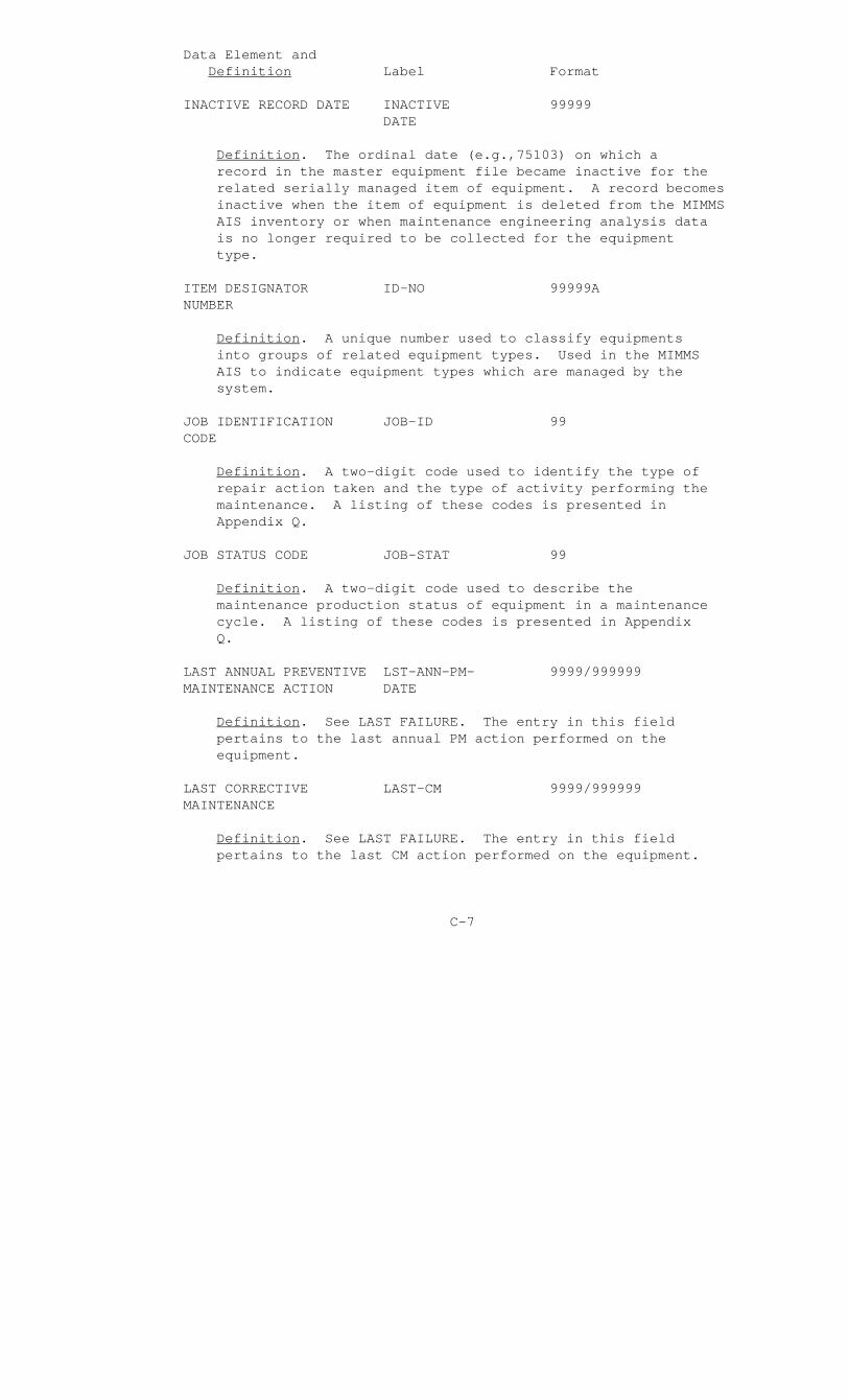
Data Element and Definition Label Format
INACTIVE RECORD DATE INACTIVE 99999 DATE
Definition. The ordinal date (e.g.,75103) on which a record in the master equipment file became inactive for the related serially managed item of equipment. A record becomes inactive when the item of equipment is deleted from the MIMMS AIS inventory or when maintenance engineering analysis data is no longer required to be collected for the equipment type.
ITEM DESIGNATOR ID-NO 99999A NUMBER
Definition. A unique number used to classify equipments into groups of related equipment types. Used in the MIMMS AIS to indicate equipment types which are managed by the system.
JOB IDENTIFICATION JOB-ID 99 CODE
Definition. A two-digit code used to identify the type of repair action taken and the type of activity performing the maintenance. A listing of these codes is presented in Appendix Q.
JOB STATUS CODE JOB-STAT 99
Definition. A two-digit code used to describe the maintenance production status of equipment in a maintenance cycle. A listing of these codes is presented in Appendix Q.
LAST ANNUAL PREVENTIVE LST-ANN-PM- 9999/999999 MAINTENANCE ACTION DATE
Definition. See LAST FAILURE. The entry in this field pertains to the last annual PM action performed on the equipment.
LAST CORRECTIVE LAST-CM 9999/999999 MAINTENANCE
Definition. See LAST FAILURE. The entry in this field pertains to the last CM action performed on the equipment.
C-7
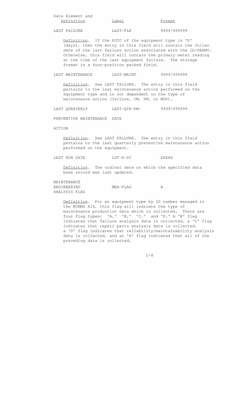
Data Element and Definition Label Format
LAST FAILURE LAST-FLR 9999/999999
Definition. If the EOTC of the equipment type is "D" (days), then the entry in this field will contain the Julian date of the last failure action associated with the ID/SERNO. Otherwise, this field will contain the primary meter reading at the time of the last equipment failure. The storage format is a four-position packed field.
LAST MAINTENANCE LAST-MAINT 9999/999999
Definition. See LAST FAILURE. The entry in this field pertains to the last maintenance action performed on the equipment type and is not dependent on the type of maintenance action (failure, CM, PM, or MOD).
LAST QUARTERLY LAST-QTR-PM- 9999/999999
PREVENTIVE MAINTENANCE DATE
ACTION
Definition. See LAST FAILURE. The entry in this field pertains to the last quarterly preventive maintenance action performed on the equipment.
LAST RUN DATE LST-R-DT XXXXX
Definition. The ordinal date on which the specified data base record was last updated.
MAINTENANCE ENGINEERING MEA-FLAG A ANALYSIS FLAG
Definition. For an equipment type by ID number managed in the MIMMS AIS, this flag will indicate the type of maintenance production data which is collected. There are four flag types: "A," "B," "C," and "D." A "B" flag indicates that failure analysis data is collected, a "C" flag indicates that repair parts analysis data is collected, a "D" flag indicates that reliability/maintainability analysis data is collected, and an "A" flag indicates that all of the preceding data is collected.
C-8
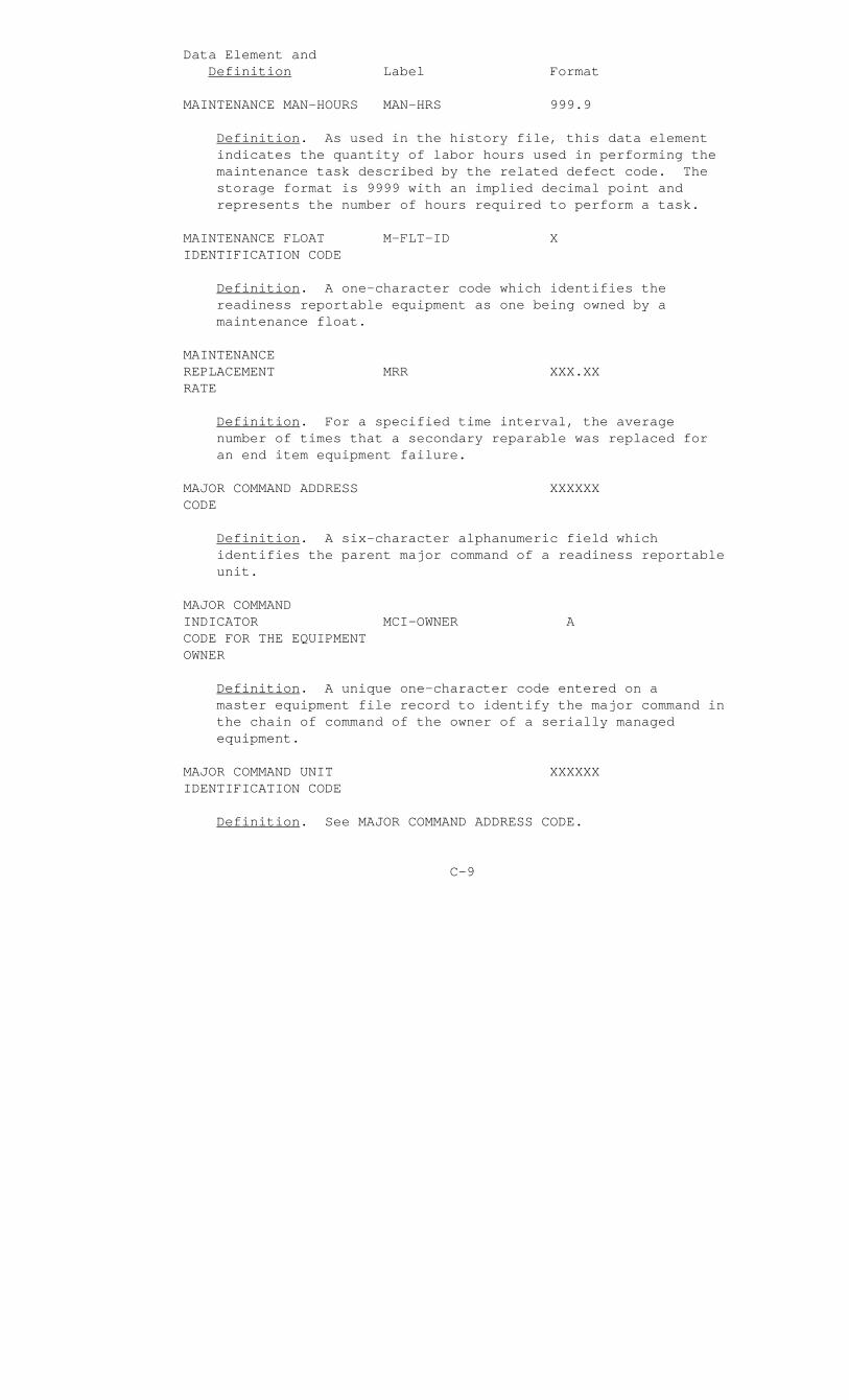
Data Element and Definition Label Format
MAINTENANCE MAN-HOURS MAN-HRS 999.9
Definition. As used in the history file, this data element indicates the quantity of labor hours used in performing the maintenance task described by the related defect code. The storage format is 9999 with an implied decimal point and represents the number of hours required to perform a task.
MAINTENANCE FLOAT M-FLT-ID X IDENTIFICATION CODE
Definition. A one-character code which identifies the readiness reportable equipment as one being owned by a maintenance float.
MAINTENANCE REPLACEMENT MRR XXX.XX RATE
Definition. For a specified time interval, the average number of times that a secondary reparable was replaced for an end item equipment failure.
MAJOR COMMAND ADDRESS XXXXXX CODE
Definition. A six-character alphanumeric field which identifies the parent major command of a readiness reportable unit.
MAJOR COMMAND INDICATOR MCI-OWNER A CODE FOR THE EQUIPMENT OWNER
Definition. A unique one-character code entered on a master equipment file record to identify the major command in the chain of command of the owner of a serially managed equipment.
MAJOR COMMAND UNIT XXXXXX IDENTIFICATION CODE
Definition. See MAJOR COMMAND ADDRESS CODE.
C-9

Data Element and Definition Label Format
MANAGEMENT FUNCTIONAL FUNCTION 99 CODE
Definition. A two-digit code indicating the functional area within which an equipment type is employed; e.g., tracked ordnance, artillery, air command/control, infantry weapons, etc.
MARINE AMPHIBIOUS MAF-CODE X FORCE CODE
Definition. A one-character code identifying the parent MAF of a readiness reportable unit.
MATERIAL EXPENSE FOR MATL-EXP-CM- 99,999.99 CORRECTIVE MAINTENANCE, LTD LIFE-TO-DATE
Definition. For a specific item of equipment, identified by an ID number and serial number, this data element will contain the total material expense incurred, since the item joined the MIMMS AIS inventory, for the performance of CM on the item. The storage format is a four-position packed field.
MATERIAL EXPENSE FOR MATL-EXP-PM- 99,999.99 PREVENTIVE MAINTENANCE, LTD LIFE-TO-DATE
Definition. For a specific item of equipment, identified by an ID number and serial number, this data element will contain the total material expense incurred, since the item joined the MIMMS AIS inventory, for the performance of PM on the item. The storage format is a four-position packed field.
MATERIAL USAGE CODE MATL-USE 9
Definition. A one-character code used to indicate the type of maintenance action which required the expenditure of the repair part. Valid codes are "7" (CM), "8" (modification maintenance), or "9" (PM). The code is the first position of the serial number segment of the requisition document number field.
C-10

Data Element and Definition Label Format
MAXIMUM TIME BETWEEN ANN-PM 999999 ANNUAL PREVENTIVE MAINTENANCE
Definition. The maximum allowable equipment operation, expressed in units of the primary meter (EOTC), between requirements to perform an annual PM action on the item of equipment.
MAXIMUM TIME BETWEEN QTRLY-PM 999999 QUARTERLY PREVENTIVE MAINTENANCE
Definition. Same as for MAXIMUM TIME BETWEEN ANNUAL PREVENTIVE MAINTENANCE, except that the timeframe is one-fourth of the annual equipment operating time.
MEAN MAINTENANCE TIME MMT 99999
Definition. The average number of maintenance man-hours required to repair an equipment once it is submitted to a maintenance activity. The storage format is a three-position packed field. MMT is computed as follows:
MMT= Sum of Maintenance Man-Hours (PM and CM) Number of Maintenance Actions (PM and CM)
MEAN TIME BETWEEN MTBF 99999 FAILURES
Definition. The average equipment operation between equipment failure actions. Units of equipment operation are expressed by the EQUIPMENT OPERATING TIME CODE for the equipment type. The storage format is a three-position packed field. MTBF is computed as follows:
MTBF = Sum of EOT Between Failures. Number of Failure Actions
C-11

Data Element and Definition Label Format
MEAN TIME BETWEEN MTBM 99999 MAINTENANCE
Definition. The average equipment operation between maintenance actions. Units of equipment operation are expressed by the EQUIPMENT OPERATING TIME CODE for the equipment type. The storage format is a three-position packed field. MTBM is computed as follows:
MTBM = Sum of EOT Between Maintenance Actions Number of Maintenance Actions
MEAN TIME TO REPAIR MTTR 99999
Definition. The average number of maintenance man-hours expended in repairing an item which requires CM. The storage format is a three-position packed field. MTTR is computed as follows:
MTTR = CM Man-Hours Number of CM Actions
SECOND ECHELON OF MAINTENANCE
Definition. Same as MEAN TIME TO REPAIR, except that only second echelon maintenance is considered.
MEAN TIME TO REPAIR MTTR-3 99999 THIRD ECHELON OF MAINTENANCE
Definition. Same as MEAN TIME TO REPAIR, except that only third echelon maintenance is considered.
C-12
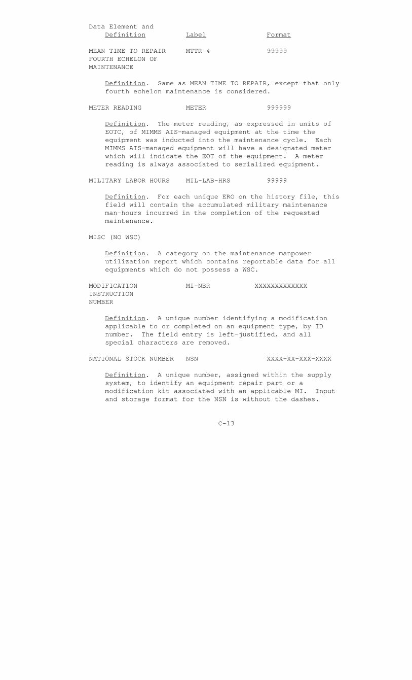
Data Element and Definition Label Format
MEAN TIME TO REPAIR MTTR-4 99999 FOURTH ECHELON OF MAINTENANCE
Definition. Same as MEAN TIME TO REPAIR, except that only fourth echelon maintenance is considered.
METER READING METER 999999
Definition. The meter reading, as expressed in units of EOTC, of MIMMS AIS-managed equipment at the time the equipment was inducted into the maintenance cycle. Each MIMMS AIS-managed equipment will have a designated meter which will indicate the EOT of the equipment. A meter reading is always associated to serialized equipment.
MILITARY LABOR HOURS MIL-LAB-HRS 99999
Definition. For each unique ERO on the history file, this field will contain the accumulated military maintenance man-hours incurred in the completion of the requested maintenance.
MISC (NO WSC)
Definition. A category on the maintenance manpower utilization report which contains reportable data for all equipments which do not possess a WSC.
MODIFICATION MI-NBR XXXXXXXXXXXXX INSTRUCTION NUMBER
Definition. A unique number identifying a modification applicable to or completed on an equipment type, by ID number. The field entry is left-justified, and all special characters are removed.
NATIONAL STOCK NUMBER NSN XXXX-XX-XXX-XXXX
Definition. A unique number, assigned within the supply system, to identify an equipment repair part or a modification kit associated with an applicable MI. Input and storage format for the NSN is without the dashes.
C-13
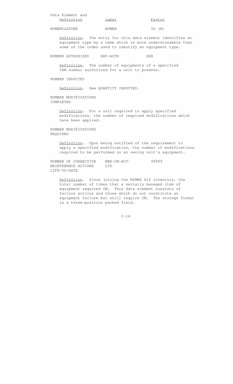
Data Element and Definition Label Factor
NOMENCLATURE NOMEN 50 (X)
Definition. The entry for this data element identifies an equipment type by a name which is more understandable than some of the codes used to identify an equipment type.
NUMBER AUTHORIZED REP-AUTH XXX
Definition. The number of equipments of a specified TAM number authorized for a unit to possess.
NUMBER INDUCTED
Definition. See QUANTITY INDUCTED.
NUMBER MODIFICATIONS COMPLETED
Definition. For a unit required to apply specified modifications, the number of required modifications which have been applied.
NUMBER MODIFICATIONS REQUIRED
Definition. Upon being notified of the requirement to apply a specified modification, the number of modifications required to be performed on an owning unit’s equipment.
NUMBER OF CORRECTIVE NBR-CM-ACT- 99999 MAINTENANCE ACTIONS LTD LIFE-TO-DATE
Definition. Since joining the MIMMS AIS inventory, the total number of times that a serially managed item of equipment required CM. This data element consists of failure actions and those which do not constitute an equipment failure but still require CM. The storage format is a three-position packed field.
C-14

Data Element and Definition Label Format
NUMBER OF FAILURE NBR-FLR-ACT- 99999 ACTIONS, LIFE-TO-DATE LTD
Definition. The total number of times that a serially managed item of equipment, while in the MIMMS AIS inventory, failed to perform its mission and required CM. The storage format is a three-position packed field.
NUMBER OF PREVENTIVE NBR-ACT-PM- 99999 MAINTENANCE ACTIONS, LTD LIFE-TO-DATE
Definition. Since joining the MIMMS AIS inventory, the total number of times that a serially managed item of equipment experienced a PM action. The storage format is a three-position packed field.
NUMBER OF TASKS NBR-TASKS 999
Definition. A field on the history file used to indicate, for a specified defect code, the number of times that a maintenance action associated with the defect code was performed in repair of the equipment associated with the ERO.
NUMBER OF TRAILERS NBR-TRLRS 99
Definition. A number used to indicate the quantity of associated "15" transaction submissions to an "11" transaction type.
NUMBER REPAIRED
Definition. The number of secondary reparables repaired for the last calendar quarter and the last year. The entry is computed as follows:
Number Inducted - Number of Washouts
NUMBER UNSERVICEABLE NBR-UNSVC 99
Definition. For an ERO, this entry indicated the number of secondary reparable items inducted which were washed out during the repair cycle.
C-15
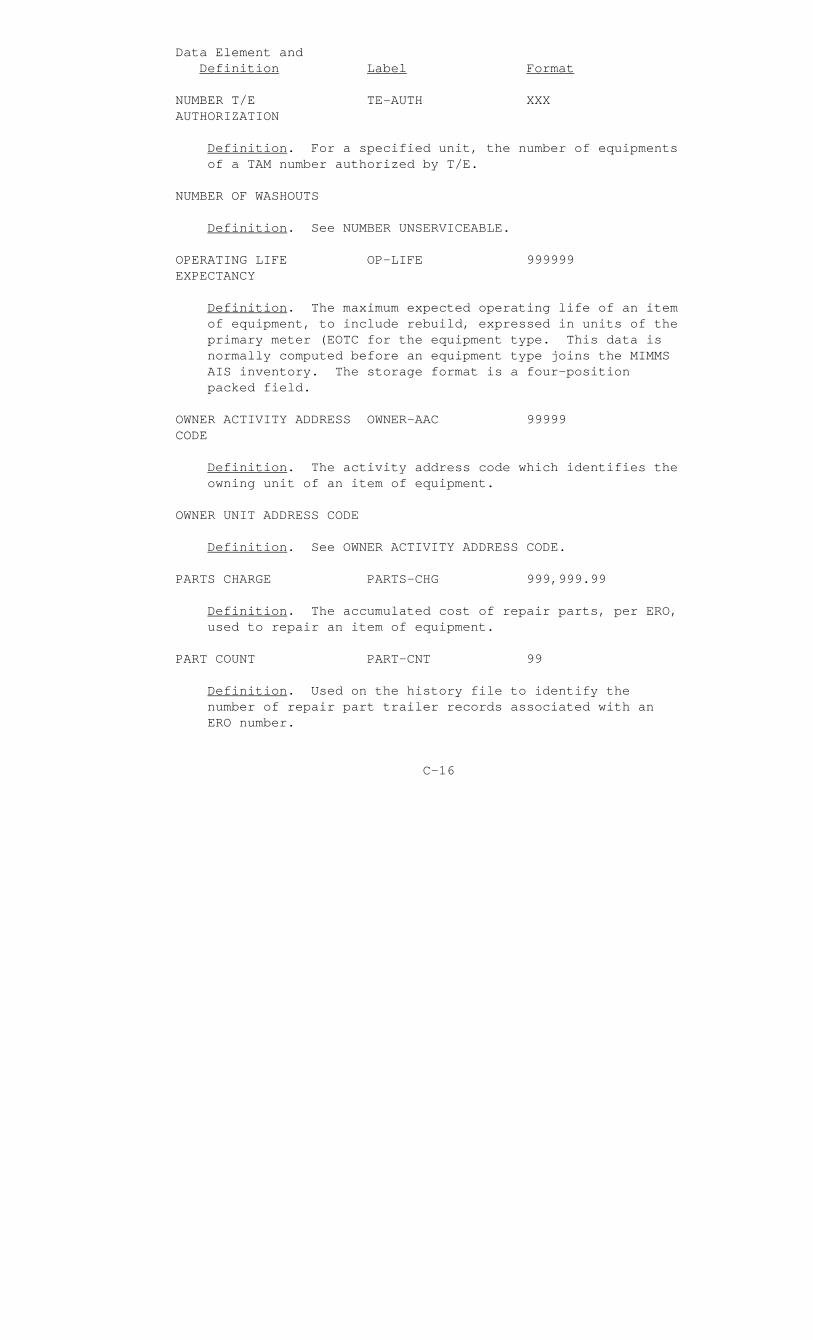
Data Element and Definition Label Format
NUMBER T/E TE-AUTH XXX AUTHORIZATION
Definition. For a specified unit, the number of equipments of a TAM number authorized by T/E.
NUMBER OF WASHOUTS
Definition. See NUMBER UNSERVICEABLE.
OPERATING LIFE OP-LIFE 999999 EXPECTANCY
Definition. The maximum expected operating life of an item of equipment, to include rebuild, expressed in units of the primary meter (EOTC for the equipment type. This data is normally computed before an equipment type joins the MIMMS AIS inventory. The storage format is a four-position packed field.
OWNER ACTIVITY ADDRESS OWNER-AAC 99999 CODE
Definition. The activity address code which identifies the owning unit of an item of equipment.
OWNER UNIT ADDRESS CODE
Definition. See OWNER ACTIVITY ADDRESS CODE.
PARTS CHARGE PARTS-CHG 999,999.99
Definition. The accumulated cost of repair parts, per ERO, used to repair an item of equipment.
PART COUNT PART-CNT 99
Definition. Used on the history file to identify the number of repair part trailer records associated with an ERO number.
C-16
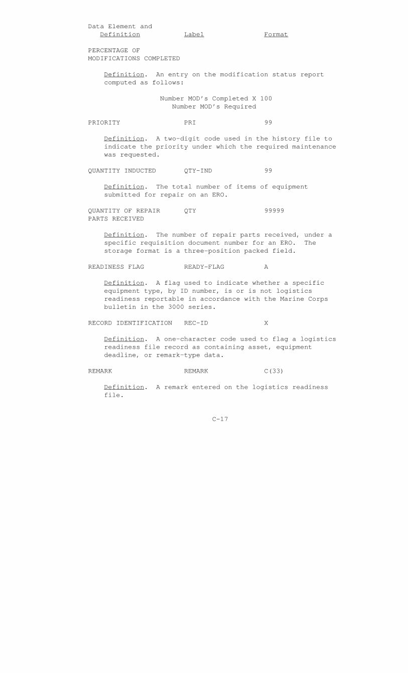
Data Element and Definition Label Format
PERCENTAGE OF MODIFICATIONS COMPLETED
Definition. An entry on the modification status report computed as follows:
Number MOD’s Completed X 100 Number MOD’s Required
PRIORITY PRI 99
Definition. A two-digit code used in the history file to indicate the priority under which the required maintenance was requested.
QUANTITY INDUCTED QTY-IND 99
Definition. The total number of items of equipment submitted for repair on an ERO.
QUANTITY OF REPAIR QTY 99999 PARTS RECEIVED
Definition. The number of repair parts received, under a specific requisition document number for an ERO. The storage format is a three-position packed field.
READINESS FLAG READY-FLAG A
Definition. A flag used to indicate whether a specific equipment type, by ID number, is or is not logistics readiness reportable in accordance with the Marine Corps bulletin in the 3000 series.
RECORD IDENTIFICATION REC-ID X
Definition. A one-character code used to flag a logistics readiness file record as containing asset, equipment deadline, or remark-type data.
REMARK REMARK C(33)
Definition. A remark entered on the logistics readiness file.
C-17

Data Element and Definition Label Format
REMARKS DATE R-DATE XXXXX
Definition. The ordinal date on which the REMARK entry on the logistics readiness file became effective.
REPAIR CYCLE TIME RCT 999
Definition. An entry on the secondary reparable expense summary report which indicates the average number of days required to repair a specified secondary reparable.
REPAIR RATE RR 999
Definition. The number of secondary reparables repaired for a specified time interval.
REPAIRED EXPENSE R-EXP 99,999.99
Definition. The total materiel expense incurred to repair secondary reparables being reported on the secondary reparable expense summary report.
REPORT STATUS REP-STAT X
Definition. A one-character code used on the logistics readiness file to indicate the readiness status of the equipment being reported.
REPORT SYMBOL RPT-SYMBOL AAX9999X99
Definition. Each preformatted HMSS report has a unique report symbol which appears in the upper right-hand corner of the report. For the MIMMS AIS only, the last two digits differ on each report.
REQUISITION DOCUMENT DOC-NO X999999999999 NUMBER
Definition. The identifying number of a document used to obtain a repair part from a source of supplies. The first five positions indicate the unit submitting the request, the next four positions indicate the Julian date on which the request was made, and the last four positions contain
C-18

Data Element and Definition Label Format
the document serial number. The first digit of the document serial number is the material usage code for the document.
SECONDARY ITEM SEC-ID X DESIGNATOR
Definition. A one-character code indicating whether the EQUIPMENT ITEM DESIGNATOR entry on the logistics readiness report is or is not the primary equipment ID for the equipment type identified by the TAM NUMBER entry.
SECONDARY REPARABLE CAT A CATEGORY CODE
Definition. A one-character code on the secondary reparable expense summary report which indicates the classification of the secondary reparable; e.g., "D" for depot reparable.
SECONDARY REPARABLE SEC-REP-CODE X CODE
Definition. A code used on the history file to indicate records which represent a maintenance action performed in repair of a secondary reparable item of equipment. Within such a record, the NSN field entry identifies the item repaired.
SERIAL NUMBER SERNO XXXXXXXXXX
Definition. A number assigned to an item of equipment to distinguish it from all other items of the same equipment type in the MIMMS AIS inventory of equipments.
STANDARD REPLACEMENT SRP 99,999.99 PRICE
Definition. An entry on the secondary reparable expense summary report of the average materiel expense incurred in maintaining a secondary reparable in the float inventory.
C-19
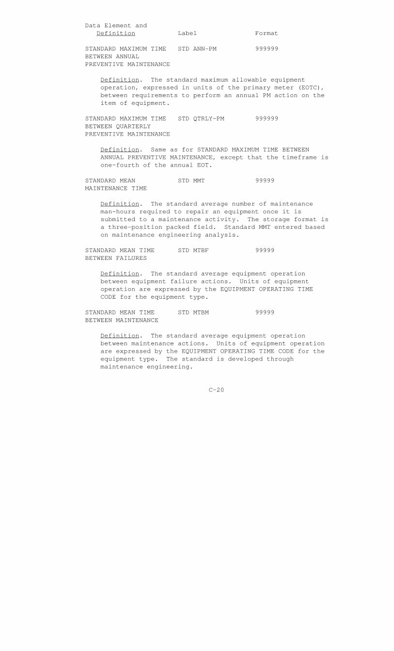
Data Element and Definition Label Format
STANDARD MAXIMUM TIME STD ANN-PM 999999 BETWEEN ANNUAL PREVENTIVE MAINTENANCE
Definition. The standard maximum allowable equipment operation, expressed in units of the primary meter (EOTC), between requirements to perform an annual PM action on the item of equipment.
STANDARD MAXIMUM TIME STD QTRLY-PM 999999 BETWEEN QUARTERLY PREVENTIVE MAINTENANCE
Definition. Same as for STANDARD MAXIMUM TIME BETWEEN ANNUAL PREVENTIVE MAINTENANCE, except that the timeframe is one-fourth of the annual EOT.
STANDARD MEAN STD MMT 99999 MAINTENANCE TIME
Definition. The standard average number of maintenance man-hours required to repair an equipment once it is submitted to a maintenance activity. The storage format is a three-position packed field. Standard MMT entered based on maintenance engineering analysis.
STANDARD MEAN TIME STD MTBF 99999 BETWEEN FAILURES
Definition. The standard average equipment operation between equipment failure actions. Units of equipment operation are expressed by the EQUIPMENT OPERATING TIME CODE for the equipment type.
STANDARD MEAN TIME STD MTBM 99999 BETWEEN MAINTENANCE
Definition. The standard average equipment operation between maintenance actions. Units of equipment operation are expressed by the EQUIPMENT OPERATING TIME CODE for the equipment type. The standard is developed through maintenance engineering.
C-20

Data Element and Definition Label Format
STANDARD ANALYSIS MTTM 999.9 TIME TO MODIFY
Definition. A standard time provided on an MI to assist maintenance managers in scheduling the application of a required modification. The storage format is a three-position packed field. The units of measurement of the MTTM are man-hours.
STANDARD MEAN TIME MTTR 99999 TO REPAIR
Definition. The standard average number of maintenance man-hours expended in repairing an item which requires CM. The standard is developed through maintenance engineering analysis.
STANDARD MEAN TIME TO STD MTTR-2 99999 REPAIR SECOND ECHELON OF MAINTENANCE
Definition. Same as STANDARD MEAN TIME TO REPAIR, except that only second echelon maintenance is considered.
STANDARD MEAN TIME TO STD MTTR-3 99999 REPAIR THIRD ECHELON OF MAINTENANCE
Definition. Same as STANDARD MEAN TIME TO REPAIR, except that only third echelon maintenance is considered.
STANDARD MEAN TIME TO STD MTTR-4 99999 REPAIR FOURTH ECHELON OF MAINTENANCE
Definition. Same as STANDARD MEAN TIME TO REPAIR, except that only fourth echelon maintenance is considered.
STATUS DATE STAT-DTE XXXXX
Definition. The original date of the latest equipment readiness status being reported.
C-21

Data Element and Definition Label Format
STATUS HOUR STAT-HR XX
Definition. The hour on the STATUS DATE of the occurrence of the reportable event.
SUM OF EQUIPMENT SUM-EOT-CM 999999999 OPERATING TIME BETWEEN CORRECTIVE MAINTENANCE, LIFE-TO-DATE
Definition. Each time that a serially managed item of equipment experiences a CM action, its operating time since the last CM action is added to the field. Values for this data element are gathered from the date the item joined the MIMMS AIS inventory. The storage format is a four-position packed field.
SUM OF EQUIPMENT SUM-EOT-FLR- 999999999 OPERATING TIME BETWEEN LTD FAILURE, LIFE-TO-DATE
Definition. Each time that a serially managed item of equipment experiences a failure, its operating time since the last failure action is added to this field. Values for this data element are gathered from the date that the item joined the MIMMS AIS inventory. The storage format is a four-position packed field.
SUPPLY STATUS CODE SUP-STAT XX
Definition. A code used to indicate the status of a requisition for a repair part.
TABLE OF AUTHORIZED TAM A9999 MATERIEL NUMBER
Definition. A number used within the Marine Corps to identify groups of end items of equipments which have similar functions.
C-22

Data Element and Definition Label Format
TOTAL CIVILIAN LABOR TOT-CIV-LAB- 9,999,999.99 EXPENSE EXP
Definition. This data element contains the summation of all CIVILIAN LABOR CHARGE expenses incurred for an item of equipment since it joined the MIMMS AIS inventory of serially managed equipment. The storage format is a four-position packed field.
TOTAL EQUIPMENT TOT-EOT 999999 OPERATING TIME
Definition. For a specific item of equipment identified by an ID number and serial number, this data element will indicate the total operating time of the equipment since it joined the MIMMS AIS inventory. The EOTC for the equipment type will indicate the units of measurement.
TOTAL MILITARY LABOR TOT-MIL-LAB- 999,999.9 HOURS HRS
Definition. This data element contains the summation of all MILITARY LABOR HOURS expended in maintaining a serially managed item of equipment since it joined the MIMMS AIS inventory. The storage format is a four-position packed field.
TRAILER COUNT TRLR-CNT 99
Definition. Same use as PART COUNT, except that it is used on the master equipment file to identify a complete modification trailer record.
TRAILER NUMBER TRLR-NBR 99
Definition. Used on the MI transaction to uniquely identify a "15" transaction type or on the MI standards file to identify a trailer record associated with a "15" transaction type submission.
C-23
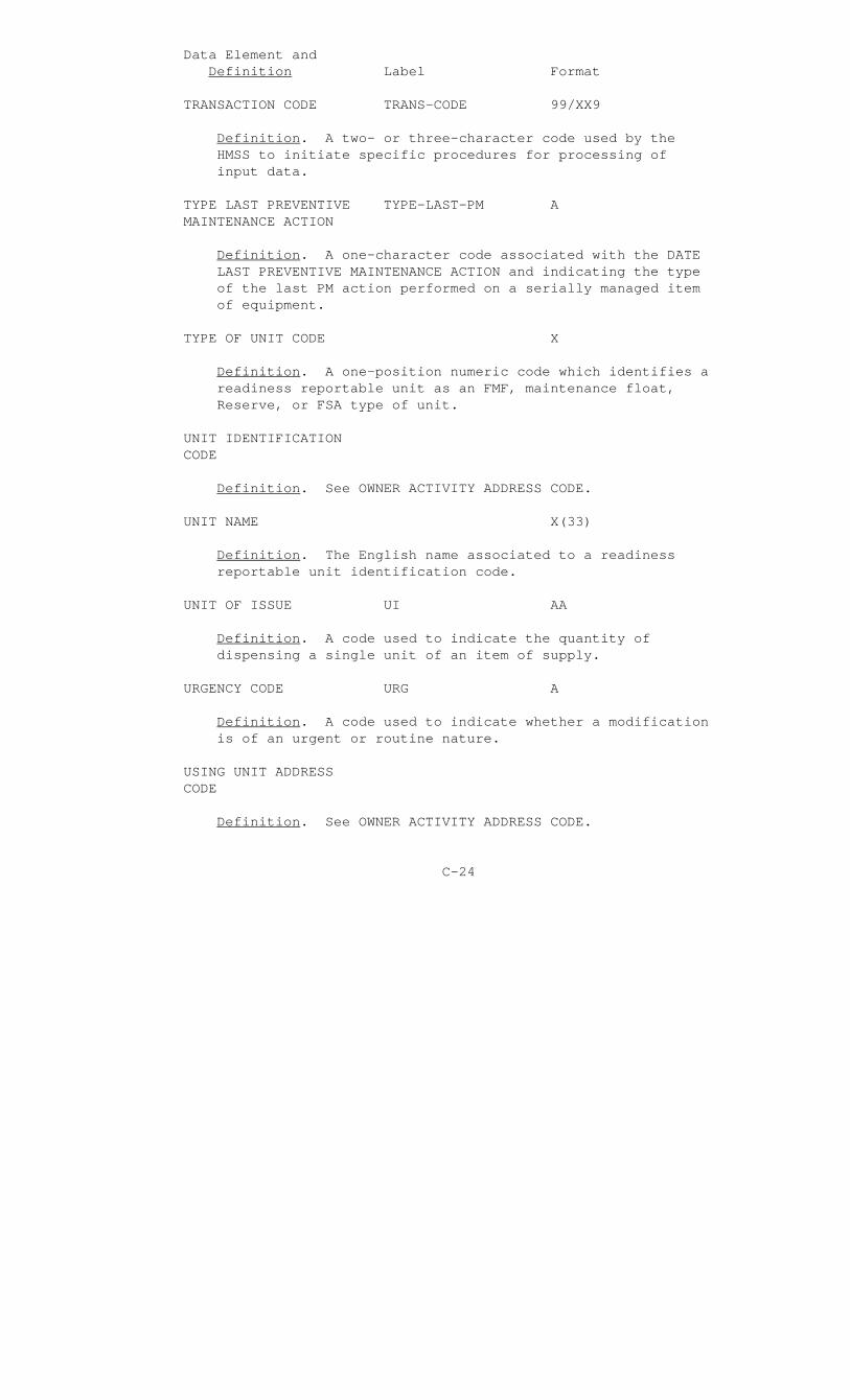
Data Element and Definition Label Format
TRANSACTION CODE TRANS-CODE 99/XX9
Definition. A two- or three-character code used by the HMSS to initiate specific procedures for processing of input data.
TYPE LAST PREVENTIVE TYPE-LAST-PM A MAINTENANCE ACTION
Definition. A one-character code associated with the DATE LAST PREVENTIVE MAINTENANCE ACTION and indicating the type of the last PM action performed on a serially managed item of equipment.
TYPE OF UNIT CODE X
Definition. A one-position numeric code which identifies a readiness reportable unit as an FMF, maintenance float, Reserve, or FSA type of unit.
UNIT IDENTIFICATION CODE
Definition. See OWNER ACTIVITY ADDRESS CODE.
UNIT NAME X(33)
Definition. The English name associated to a readiness reportable unit identification code.
UNIT OF ISSUE UI AA
Definition. A code used to indicate the quantity of dispensing a single unit of an item of supply.
URGENCY CODE URG A
Definition. A code used to indicate whether a modification is of an urgent or routine nature.
USING UNIT ADDRESS CODE
Definition. See OWNER ACTIVITY ADDRESS CODE.
C-24
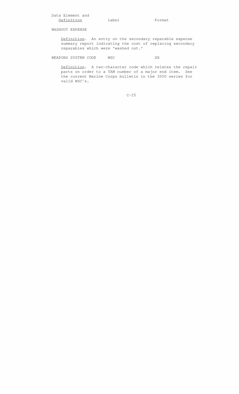
Data Element and Definition Label Format
WASHOUT EXPENSE
Definition. An entry on the secondary reparable expense summary report indicating the cost of replacing secondary reparables which were "washed out."
WEAPONS SYSTEM CODE WSC XX
Definition. A two-character code which relates the repair parts on order to a TAM number of a major end item. See the current Marine Corps bulletin in the 3000 series for valid WSC’s.
C-25
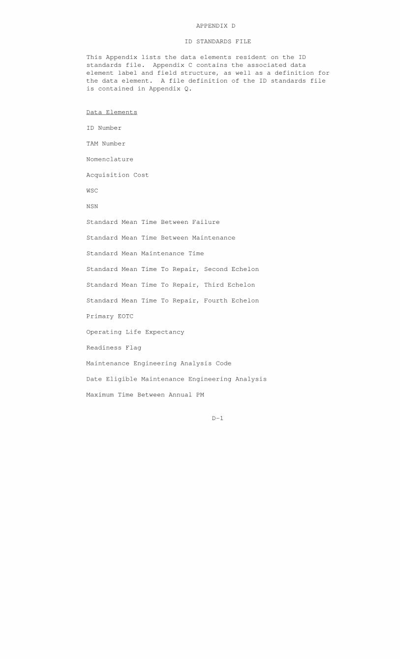
APPENDIX D
ID STANDARDS FILE
This Appendix lists the data elements resident on the ID standards file. Appendix C contains the associated data element label and field structure, as well as a definition for the data element. A file definition of the ID standards file is contained in Appendix Q.
Data Elements
ID Number
TAM Number
Nomenclature
Acquisition Cost
WSC
NSN
Standard Mean Time Between Failure
Standard Mean Time Between Maintenance
Standard Mean Maintenance Time
Standard Mean Time To Repair, Second Echelon
Standard Mean Time To Repair, Third Echelon
Standard Mean Time To Repair, Fourth Echelon
Primary EOTC
Operating Life Expectancy
Readiness Flag
Maintenance Engineering Analysis Code
Date Eligible Maintenance Engineering Analysis
Maximum Time Between Annual PM
D-1

Data Elements (cont.)
Maximum Time Between Quarterly PM
Modification Control Flag
Management Functional Codes (Refer to MCO 3000.12)
D-2

APPENDIX E
MI STANDARDS FILE
This Appendix lists the data elements resident on the MI standards file. Appendix C contains the associated data element label and field structure, as well as a definition for the data element. A file definition of the MI standards file is contained in Appendix Q.
Data Elements
MI Number
ID Number
Urgency Code
Date of Last Update
Date the Record was Established
Standard Time to Modify
New ID Number Resulting From Application of the Modification (New ID)
Modification Kit NSN (NSN)
Weapon Systems Code
Trailer Count
MI Standards File Trailer Record
Trailer Number
Serial Number From
Serial Number To
E-1

APPENDIX F
EDIT STANDARDS FILE
This Appendix lists the data elements which comprise the edit standards file. The edit standards file consists of five tables of valid codes and abbreviations. Appendix C contains the associated data element label and field structure, as well as a definition for the data element.
Data Elements
Table of First Characters of the Defect Code
Defect Code First Character
Defect Code First Character Abbreviation
Table of Second and Third Characters of the Defect Code
Defect Code Second and Third Characters
Defect Code Second and Third Characters Abbreviation
Table of Job Status Codes
Job Status Code
Job Status Code Abbreviation
Table of First Characters of the Job Identification Code
Job Identification Code First Character
Job Identification Code First Character Abbreviation
Table of Second Characters of the Job Identification Code
Job Identification Code Second Character
Job Identification Code Second Character Abbreviation
F-1
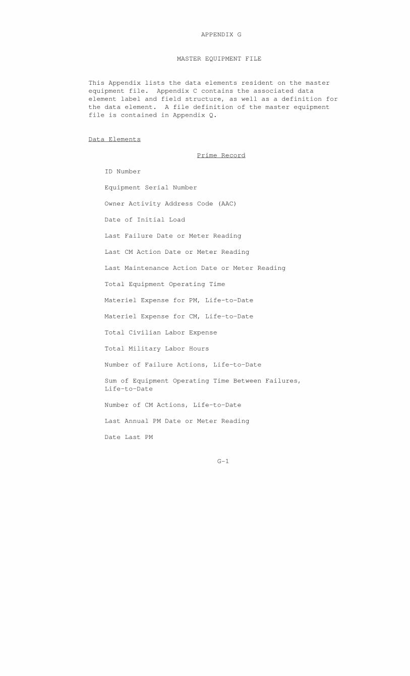
APPENDIX G
MASTER EQUIPMENT FILE
This Appendix lists the data elements resident on the master equipment file. Appendix C contains the associated data element label and field structure, as well as a definition for the data element. A file definition of the master equipment file is contained in Appendix Q.
Data Elements
Prime Record
ID Number
Equipment Serial Number
Owner Activity Address Code (AAC)
Date of Initial Load
Last Failure Date or Meter Reading
Last CM Action Date or Meter Reading
Last Maintenance Action Date or Meter Reading
Total Equipment Operating Time
Materiel Expense for PM, Life-to-Date
Materiel Expense for CM, Life-to-Date
Total Civilian Labor Expense
Total Military Labor Hours
Number of Failure Actions, Life-to-Date
Sum of Equipment Operating Time Between Failures, Life-to-Date
Number of CM Actions, Life-to-Date
Last Annual PM Date or Meter Reading
Date Last PM
G-1
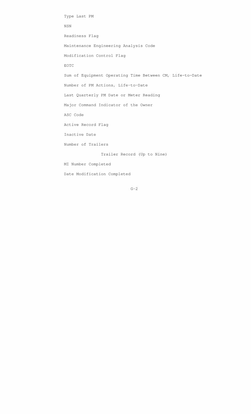
Type Last PM
NSN
Readiness Flag
Maintenance Engineering Analysis Code
Modification Control Flag
EOTC
Sum of Equipment Operating Time Between CM, Life-to-Date
Number of PM Actions, Life-to-Date
Last Quarterly PM Date or Meter Reading
Major Command Indicator of the Owner
ASC Code
Active Record Flag
Inactive Date
Number of Trailers
Trailer Record (Up to Nine)
MI Number Completed
Date Modification Completed
G-2

APPENDIX H
HISTORY FILE
This Appendix lists the data elements resident on the history file. Appendix C contains the associated data element label and field structure, as well as a definition for the data element. A file definition of the history file is contained in Appendix Q. A history file record consists of a prime record and from 0 to 99 trailer records.
Data Elements
Prime Record
Secondary Reparable Code
ID Number
Equipment Serial Number
Date Received in Shop
ERO Number
NSN
Owner AAC
Echelon of Maintenance
Job Identification Code
Quantity Inducted
Cross-Reference ERO Number 1
Cross-Reference ERO Number 2
Priority
Category Code
Deadline Control Date
Date Closed
Civilian Labor Charge
H-1

Parts Charge
Military Labor Hours
EOTC
Meter Reading
Task Data 1
Task Data 2
Task Data 3
Number Unserviceable
ASC Code
Readiness Flag
MEA Flag
Number of Trailers
Trailer Record
Advice Code
NSN
Document Number or MI Number
Unit of Issue
Quantity
Date Received
H-2

APPENDIX I
UNIT DATA FILE
This Appendix lists the data elements resident on the unit data file. Appendix C contains the associated data element label and field structure, as well as a definition for the data element. A file definition of the unit data file is contained in Appendix Q.
Data Elements
Unit Identification Code
Unit Name
Major Command Unit Identification Code
Type Unit Code
Marine Amphibious Force Code
I-1

APPENDIX J
TAM DATA FILE
This Appendix lists the data elements resident on the TAM file. Appendix C contains the associated data element label and field structure, as well as a definition for the data element. A file definition for the TAM file is contained in Appendix Q.
Data Elements
TAM Number
Nomenclature
Management Functional Codes (Refer to MCO 3000.12)
J-1
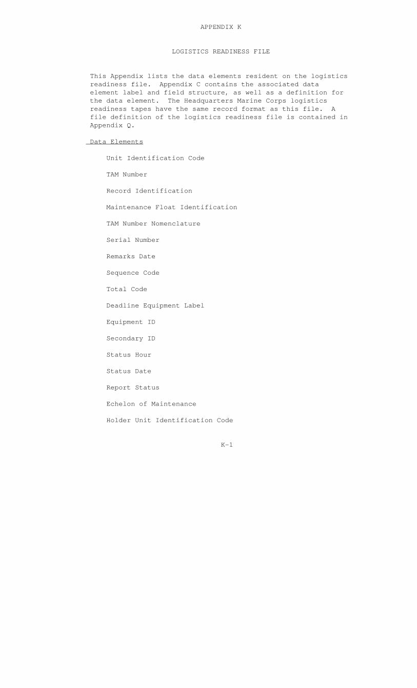
APPENDIX K
LOGISTICS READINESS FILE
This Appendix lists the data elements resident on the logistics readiness file. Appendix C contains the associated data element label and field structure, as well as a definition for the data element. The Headquarters Marine Corps logistics readiness tapes have the same record format as this file. A file definition of the logistics readiness file is contained in Appendix Q.
Data Elements
Unit Identification Code
TAM Number
Record Identification
Maintenance Float Identification
TAM Number Nomenclature
Serial Number
Remarks Date
Sequence Code
Total Code
Deadline Equipment Label
Equipment ID
Secondary ID
Status Hour
Status Date
Report Status
Echelon of Maintenance
Holder Unit Identification Code
K-1
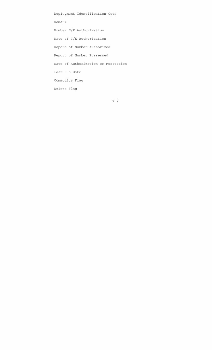
Deployment Identification Code
Remark
Number T/E Authorization
Date of T/E Authorization
Report of Number Authorized
Report of Number Possessed
Date of Authorization or Possession
Last Run Date
Commodity Flag
Delete Flag
K-2
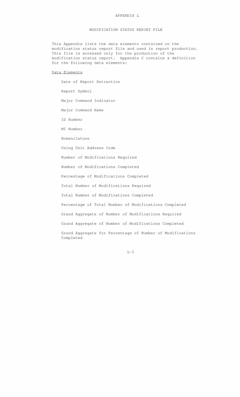
APPENDIX L
MODIFICATION STATUS REPORT FILE
This Appendix lists the data elements contained on the modification status report file and used in report production. This file is accessed only for the production of the modification status report. Appendix C contains a definition for the following data elements:
Data Elements
Date of Report Extraction
Report Symbol
Major Command Indicator
Major Command Name
ID Number
MI Number
Nomenclature
Using Unit Address Code
Number of Modifications Required
Number of Modifications Completed
Percentage of Modifications Completed
Total Number of Modifications Required
Total Number of Modifications Completed
Percentage of Total Number of Modifications Completed
Grand Aggregate of Number of Modifications Required
Grand Aggregate of Number of Modifications Completed
Grand Aggregate for Percentage of Number of Modifications Completed
L-1
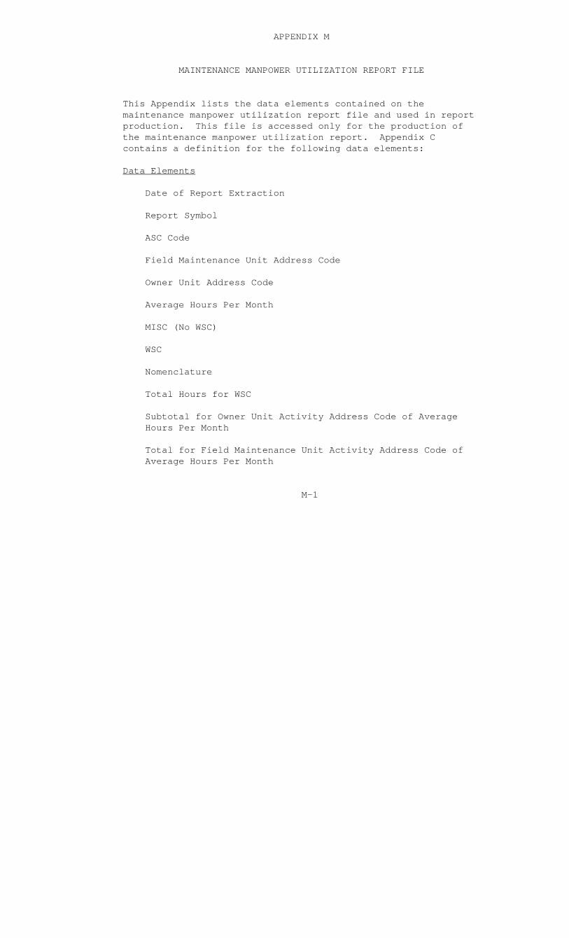
APPENDIX M
MAINTENANCE MANPOWER UTILIZATION REPORT FILE
This Appendix lists the data elements contained on the maintenance manpower utilization report file and used in report production. This file is accessed only for the production of the maintenance manpower utilization report. Appendix C contains a definition for the following data elements:
Data Elements
Date of Report Extraction
Report Symbol
ASC Code
Field Maintenance Unit Address Code
Owner Unit Address Code
Average Hours Per Month
MISC (No WSC)
WSC
Nomenclature
Total Hours for WSC
Subtotal for Owner Unit Activity Address Code of Average Hours Per Month
Total for Field Maintenance Unit Activity Address Code of Average Hours Per Month
M-1
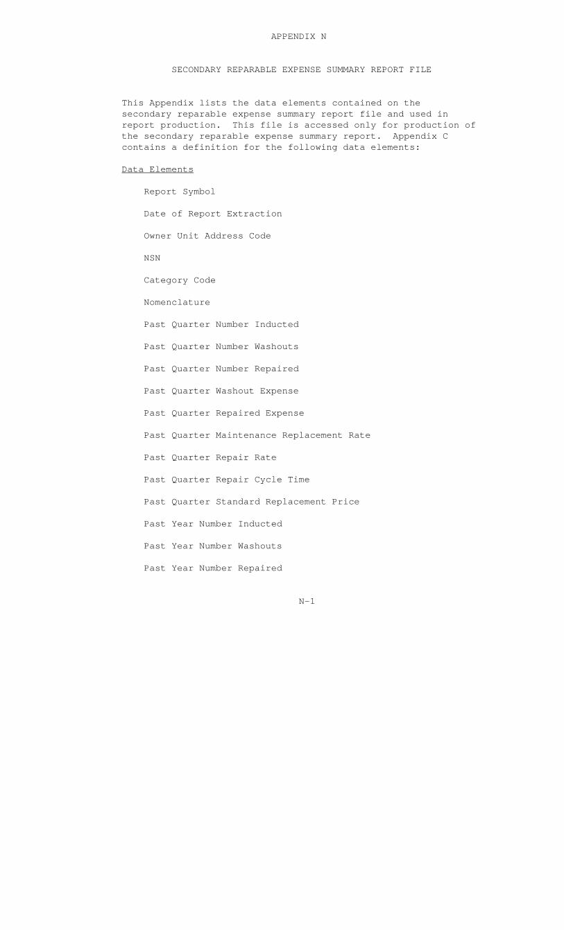
APPENDIX N
SECONDARY REPARABLE EXPENSE SUMMARY REPORT FILE
This Appendix lists the data elements contained on the secondary reparable expense summary report file and used in report production. This file is accessed only for production of the secondary reparable expense summary report. Appendix C contains a definition for the following data elements:
Data Elements
Report Symbol
Date of Report Extraction
Owner Unit Address Code
NSN
Category Code
Nomenclature
Past Quarter Number Inducted
Past Quarter Number Washouts
Past Quarter Number Repaired
Past Quarter Washout Expense
Past Quarter Repaired Expense
Past Quarter Maintenance Replacement Rate
Past Quarter Repair Rate
Past Quarter Repair Cycle Time
Past Quarter Standard Replacement Price
Past Year Number Inducted
Past Year Number Washouts
Past Year Number Repaired
N-1
Past Year Washout Expense
Past Year Repaired Expense
Past Year Maintenance Replacement Rate
Past Year Repair Rate
Past Year Repair Cycle Time
Past Year Standard Replacement Price
N-2

APPENDIX O
HISTORICAL MAINTENANCE ENGINEERING FILE
This Appendix will explain the composition of the historical maintenance engineering file. The file is composed of data elements resident on the ID standards, edit standards, master equipment, and history files. Appendix C contains the associated data element label and field structure, as well as a definition for the data element. A file definition of the historical maintenance engineering file is contained in Appendix Q. A historical maintenance engineering file record consists of three types of records which are labeled ID standards extract, history extract, and master equipment extract.
Data Elements
ID STANDARDS EXTRACT
Type of Record
Complete ID Standards File Record for ID Number
History Extract
Type of Record
Complete History File Record for ID Number Plus the Defect Code Nomenclature for Each First, Second, and Third Task Data Entry on the History Prime Record
Master Equipment Extract
Type of Record
Complete Master Equipment File Record for ID Number
O-1
APPENDIX P
GLOSSARY FOR HMSS FILE DEFINITIONS
This Appendix contains a MARK IV glossary and file definitions of the respective files resident in the HMSS. By referring to these file definitions, a user can obtain the information necessary to initiate a data retrieval request. Additionally, the user can discern the columnar headings for a data element as it will appear on the resultant output reports.
P-1
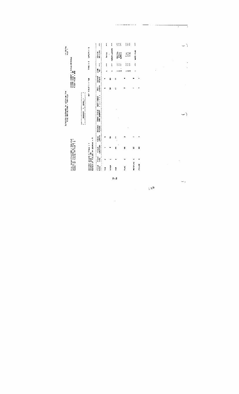


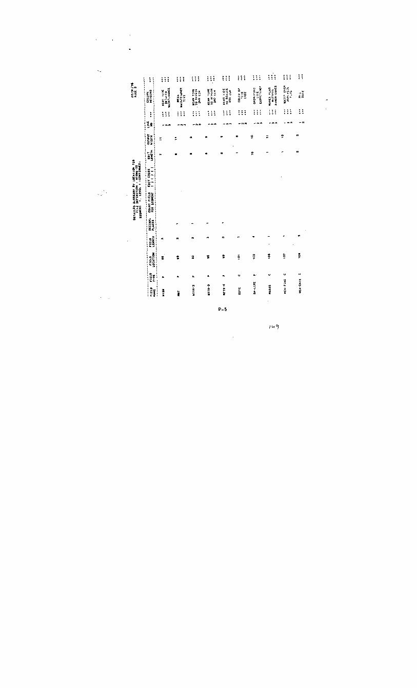
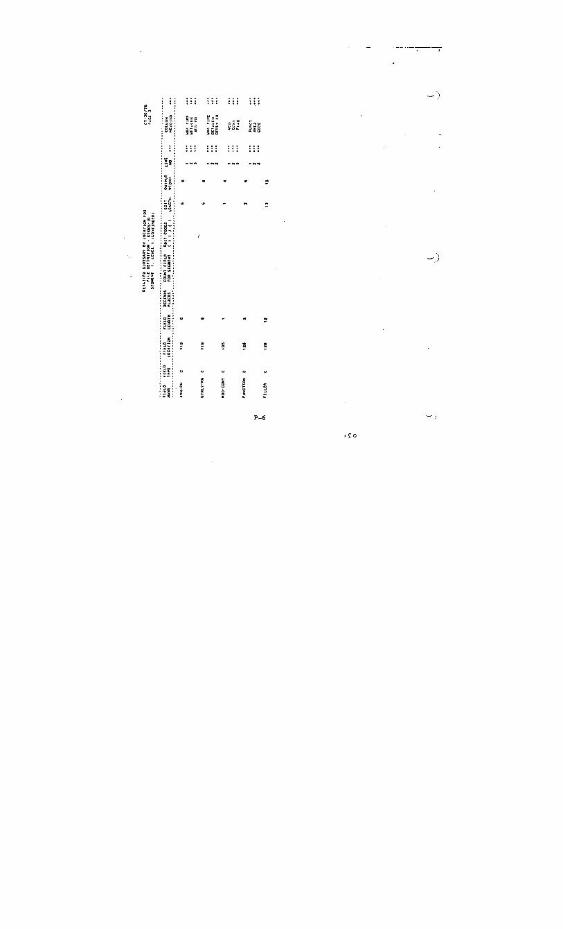

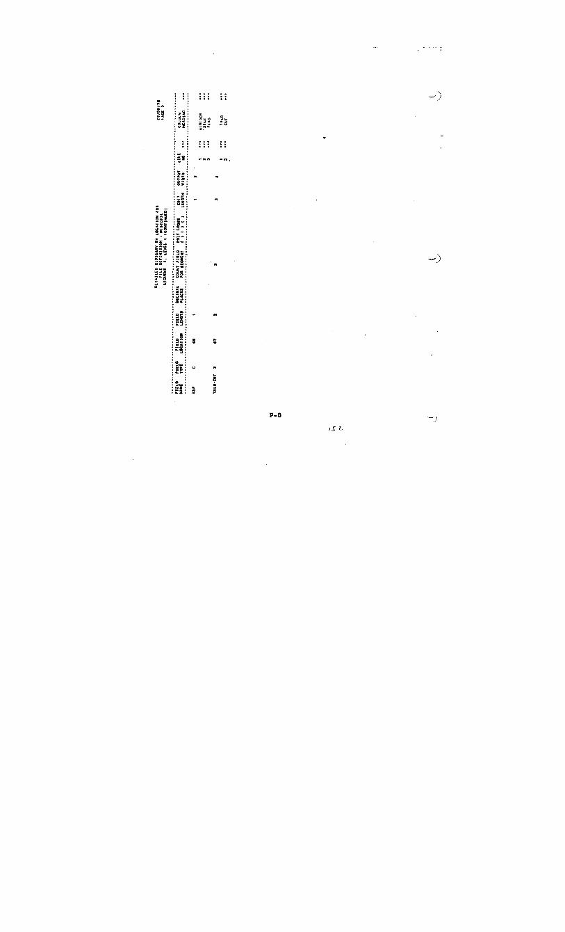
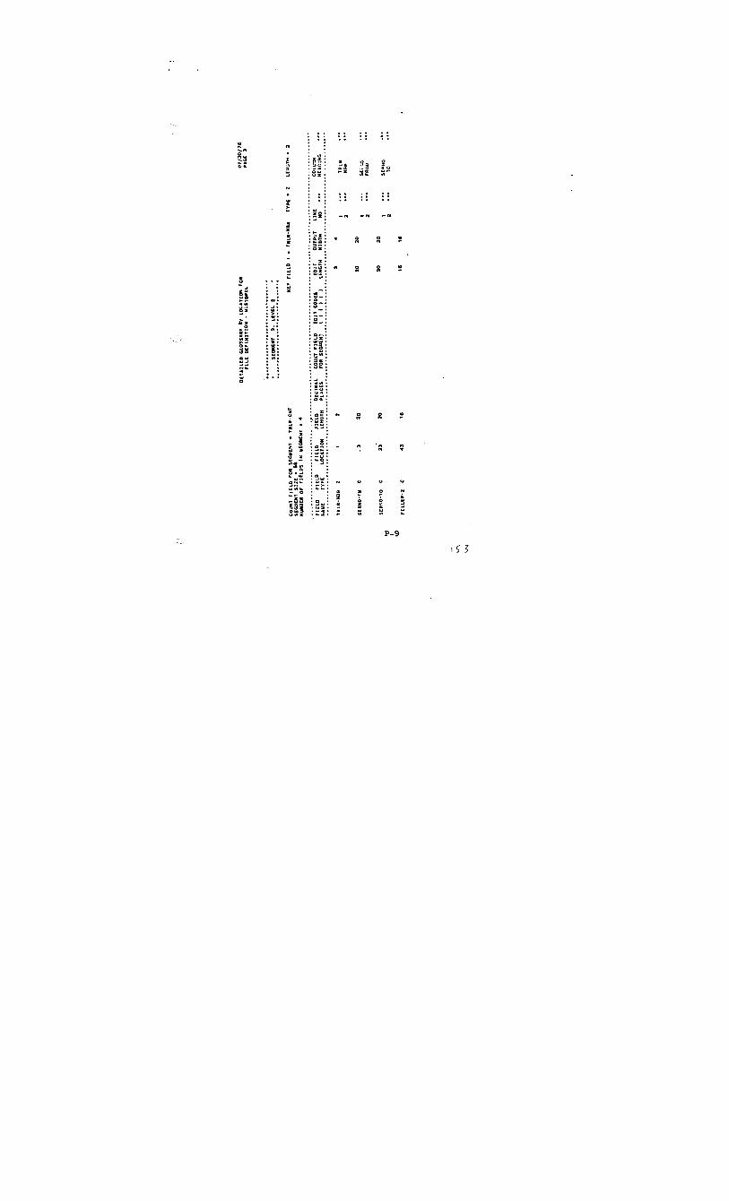


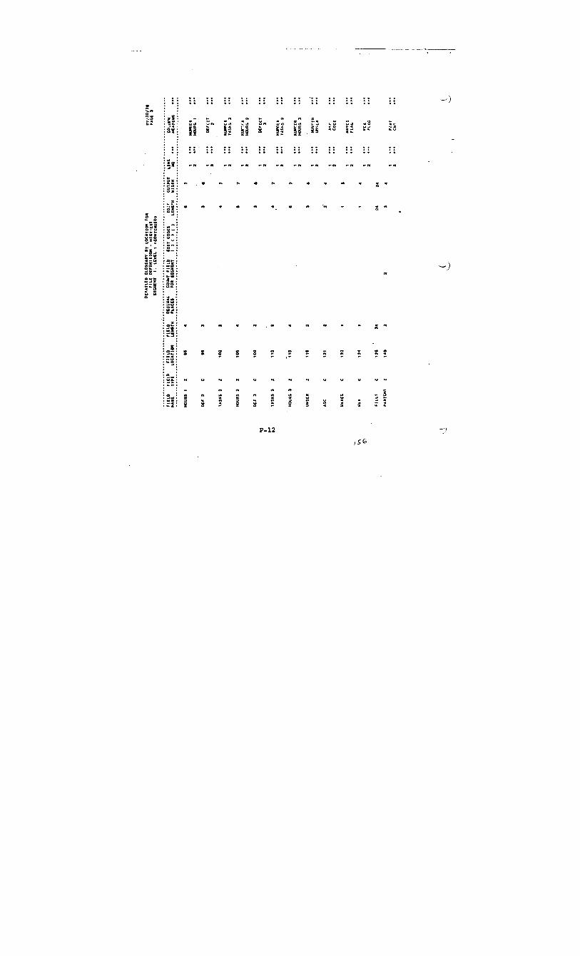
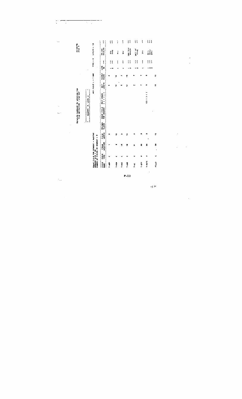

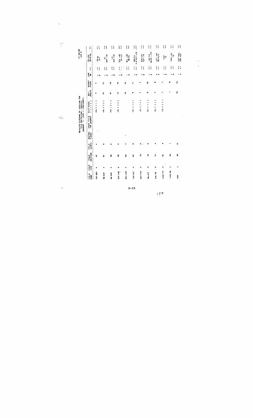
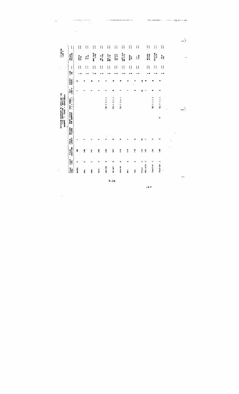

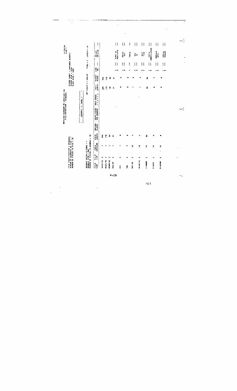
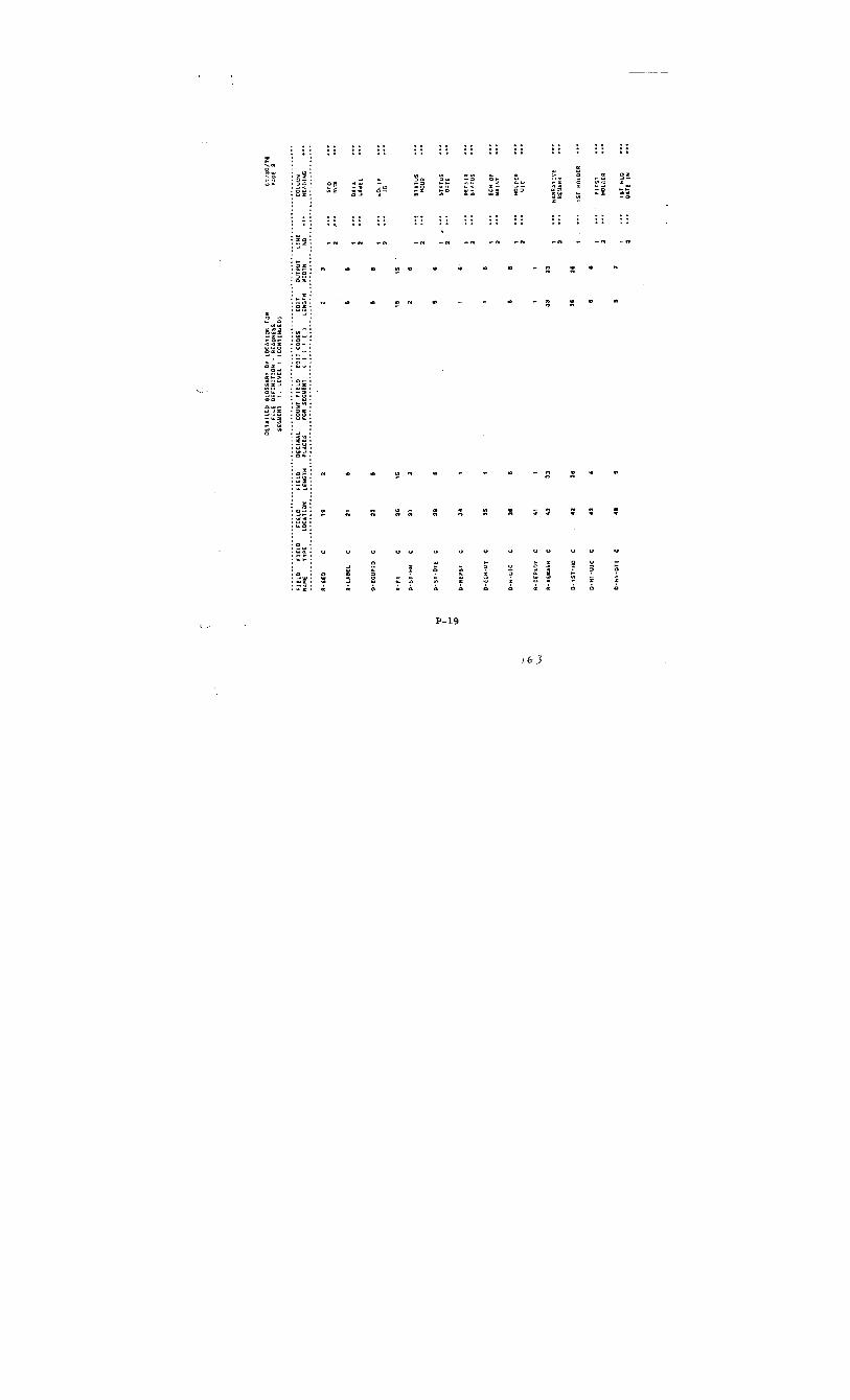
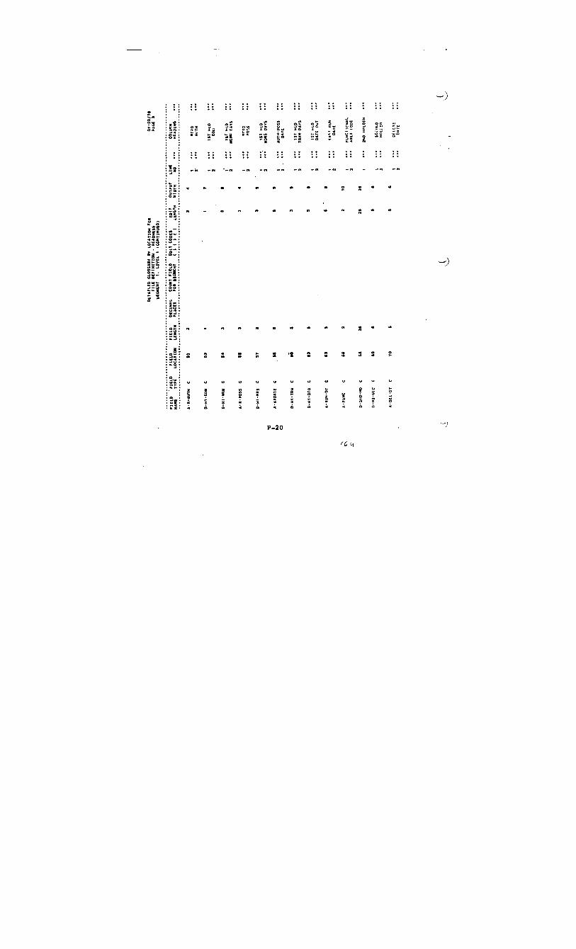
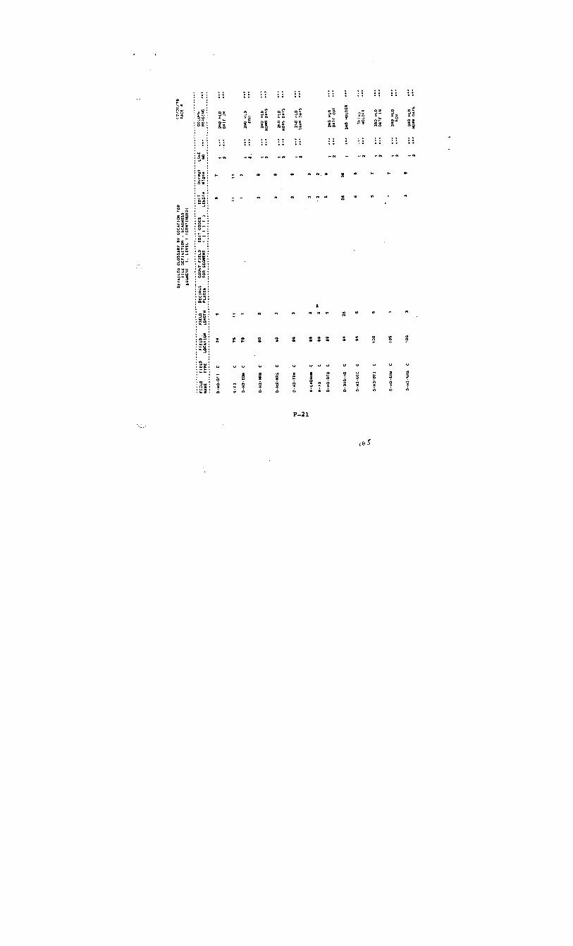
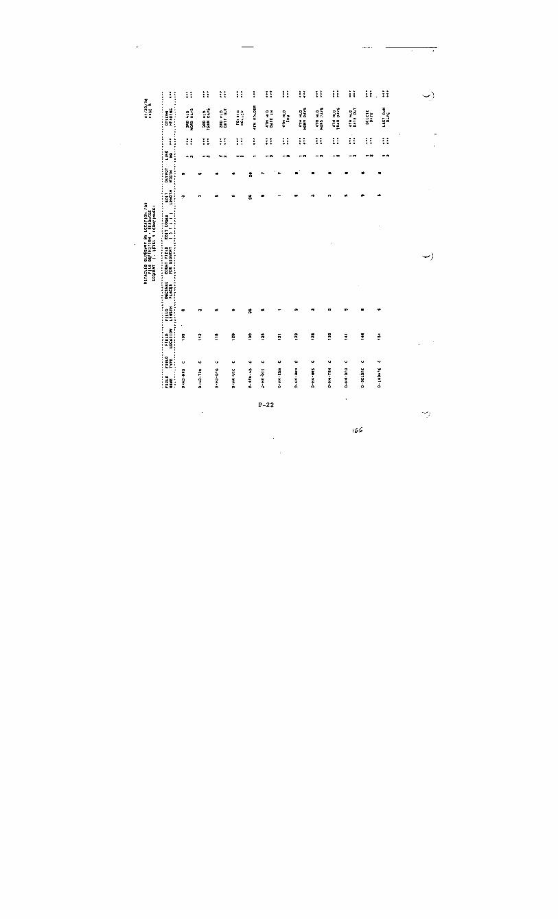

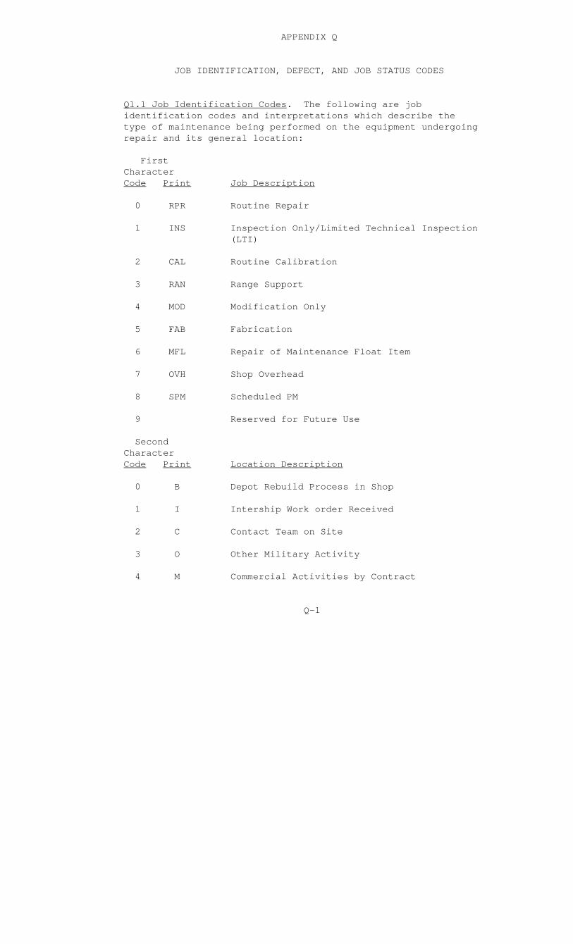
APPENDIX Q
JOB IDENTIFICATION, DEFECT, AND JOB STATUS CODES
Q1.1 Job Identification Codes. The following are job identification codes and interpretations which describe the type of maintenance being performed on the equipment undergoing repair and its general location:
First Character Code Print Job Description
0 RPR Routine Repair
1 INS Inspection Only/Limited Technical Inspection (LTI)
2 CAL Routine Calibration
3 RAN Range Support
4 MOD Modification Only
5 FAB Fabrication
6 MFL Repair of Maintenance Float Item
7 OVH Shop Overhead
8 SPM Scheduled PM
9 Reserved for Future Use
Second Character Code Print Location Description
0 B Depot Rebuild Process in Shop
1 I Intership Work order Received
2 C Contact Team on Site
3 O Other Military Activity
4 M Commercial Activities by Contract
Q-1

Second Character Code Print Location Description
5 S In Shop
6-9 Reserved for Future Use
Q-2
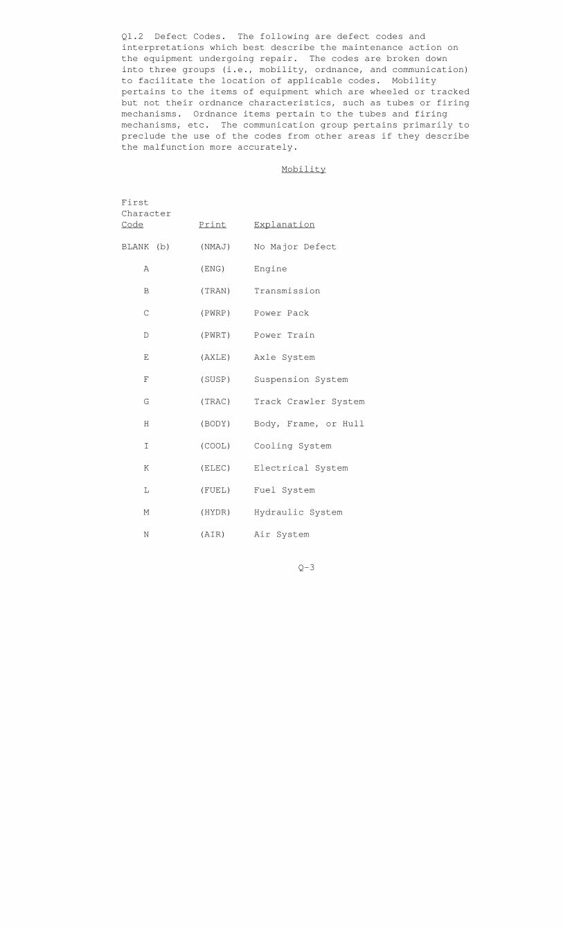
Q1.2 Defect Codes. The following are defect codes and interpretations which best describe the maintenance action on the equipment undergoing repair. The codes are broken down into three groups (i.e., mobility, ordnance, and communication) to facilitate the location of applicable codes. Mobility pertains to the items of equipment which are wheeled or tracked but not their ordnance characteristics, such as tubes or firing mechanisms. Ordnance items pertain to the tubes and firing mechanisms, etc. The communication group pertains primarily to preclude the use of the codes from other areas if they describe the malfunction more accurately.
Mobility
First Character Code Print Explanation
BLANK (b) (NMAJ) No Major Defect
A (ENG) Engine
B (TRAN) Transmission
C (PWRP) Power Pack
D (PWRT) Power Train
E (AXLE) Axle System
F (SUSP) Suspension System
G (TRAC) Track Crawler System
H (BODY) Body, Frame, or Hull
I (COOL) Cooling System
K (ELEC) Electrical System
L (FUEL) Fuel System
M (HYDR) Hydraulic System
N (AIR) Air System
Q-3

First Explanation Character Code Print
Q (IGNI) Ignition System
R (LIFT) Boom, Cable, and Lift System
X (MTR) Meter
2 (TEDD) Test Equipment/Display Devices
3 (A/C) Air-Conditioners
Ordnance
First Character Code Print Explanation
BLANK (b) (NMAJ) No Major Defect
H (BODY) Body, Frame, or Hull
I (ARMT) Armament
K (ELEC) Electrical System
N (AIR) Air System
O (TURR) Turret System
P (FCON) Fire Control System
X (MTR) Meter
Y (WPNS) Weapons/Small Arms/Crew-Served
Z (LVTP) Landing Vehicle Track Personnel
2 (TEDD) Test Equipment/Display Devices
Q-4

Communication
First Character Code Print Explanation
BLANK (b) (NMAJ) No Major Defect
S (XMOC) Transmitter/Output Circuitry
T (RCIC) Receiver/Input Circuitry
U (ANTL) Antenna/Transmission Line
V (MODM) Multiplex/Modulation-Demodulation
W (DADI) Data/Digital Systems
X (MTR) Meter
1 (ANEW) Ancillary Equipment/Wiring
2 (TEDD) Test Equipment/Display Devices
3 (A/C) Air-Conditioners
Mobility
Second and Third Character Code Print Explanation
01 (ALGEN) Alternator, Generator Mechanism
02 (BRK) Brake Systems and Components
03 (CARB) Carburetion Systems
04 (CARR) Carriage and Mount Mechanism
05 (CONV) Clutch, Converter, and Couplings
06 (CONT) Control Mechanisms
07 (CYL) Cylinders, Accumulators, and Replenishers
Q-5
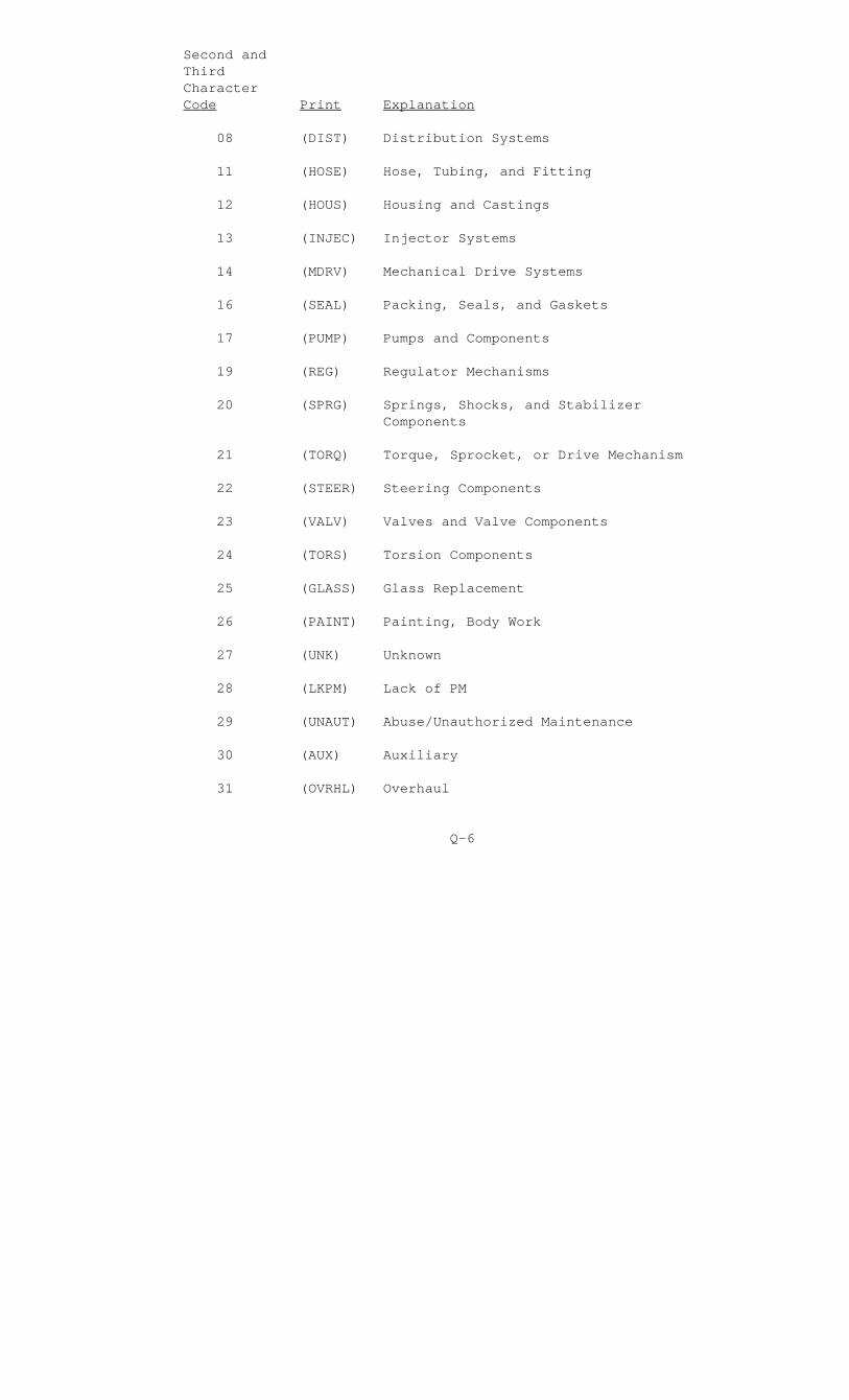
Second and Third Character Code Print Explanation
08 (DIST) Distribution Systems
11 (HOSE) Hose, Tubing, and Fitting
12 (HOUS) Housing and Castings
13 (INJEC) Injector Systems
14 (MDRV) Mechanical Drive Systems
16 (SEAL) Packing, Seals, and Gaskets
17 (PUMP) Pumps and Components
19 (REG) Regulator Mechanisms
20 (SPRG) Springs, Shocks, and Stabilizer Components
21 (TORQ) Torque, Sprocket, or Drive Mechanism
22 (STEER) Steering Components
23 (VALV) Valves and Valve Components
24 (TORS) Torsion Components
25 (GLASS) Glass Replacement
26 (PAINT) Painting, Body Work
27 (UNK) Unknown
28 (LKPM) Lack of PM
29 (UNAUT) Abuse/Unauthorized Maintenance
30 (AUX) Auxiliary
31 (OVRHL) Overhaul
Q-6

Second and Third Character Code Print Explanation
34 (RPLC) Replace
39 (CORR) Corroded/Rusted
42 (MECH) Mechanical/Linkage or Drive
44 (ALGN) System Alignment
48 (CBB) Cracked, Broken, or Bent
51 (QSPM) Quarterly Schedule PM
52 (ASPM) Annual Scheduled PM
53 (SAPM) Semiannual Scheduled PM
55 (INOP) Inoperative
56 (MINR) Minor
57 (ADJS) Adjust
60 (SAFDL) Safety Deadline
61 (START) Starter
62 (BTRY) Battery
63 (EXSYS) Exhaust System
Ordnance
Second and Third Character Code Print Explanation
09 (ELTR) Elevation and Traversing Mechanisms
10 (GUN) Gun Tube, Breech, and Firing Mechanisms
Q-7
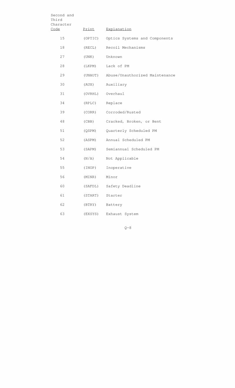
Second and Third Character Code Print Explanation
15 (OPTIC) Optics Systems and Components
18 (RECL) Recoil Mechanisms
27 (UNK) Unknown
28 (LKPM) Lack of PM
29 (UNAUT) Abuse/Unauthorized Maintenance
30 (AUX) Auxiliary
31 (OVRHL) Overhaul
34 (RPLC) Replace
39 (CORR) Corroded/Rusted
48 (CBB) Cracked, Broken, or Bent
51 (QSPM) Quarterly Scheduled PM
52 (ASPM) Annual Scheduled PM
53 (SAPM) Semiannual Scheduled PM
54 (N/A) Not Applicable
55 (INOP) Inoperative
56 (MINR) Minor
60 (SAFDL) Safety Deadline
61 (START) Starter
62 (BTRY) Battery
63 (EXSYS) Exhaust System
Q-8

Communication
Second and Third Character Code Print Explanation
16 (SEAL) Packing, Seals, and Gaskets
27 (UNK) Unknown
28 (LKPM) Lack of PM
29 (UNAUT) Abuse/Unauthorized Maintenance
30 (AUX) Auxiliary
32 (REFP) Reflected Power
33 (HVSWR) High-Voltage Standing Wave Ratio
34 (RPLC) Replace
35 (FREQ) Frequency Shift/Stability
36 (ADJS) Subassembly Adjustment
37 (CABL) Cabling Malfunction
38 (LPO) Low Power Out
39 (CORR) Corroded/Rusted
40 (OPEN) Open/High-Resistive Circuitry
41 (SHORT) Shorted/Low-Resistive Circuitry
42 (MECH) Mechanical/Linkage or Drive
43 (ACDCS) Alternating Current/Direct Current Source
44 (ALGN) System Alignment
45 (MODUL) Modulator
46 (LVPS) Low-Voltage Power Supply
Q-9

Second and Third Character Code Print Explanation
47 (HVPS) High-Voltage Power Supply
48 (CBB) Cracked, Broken, or Bent
49 (GRND) Grounded
50 (COTO) Components Out of Tolerance
51 (QSPM) Quarterly Scheduled PM
52 (ASPM) Annual Scheduled PM
54 (N/A) Not Applicable
55 (INOP) Inoperative
56 (MINR) Minor
58 (MOIST) Moisture Found
59 (ARCB) Arcing/Burnt Components
60 (SAFDL) Safety Deadline
61 (START) Starter
62 (BTRY) Battery
63 (EXSYS) Exhaust System
Q-10
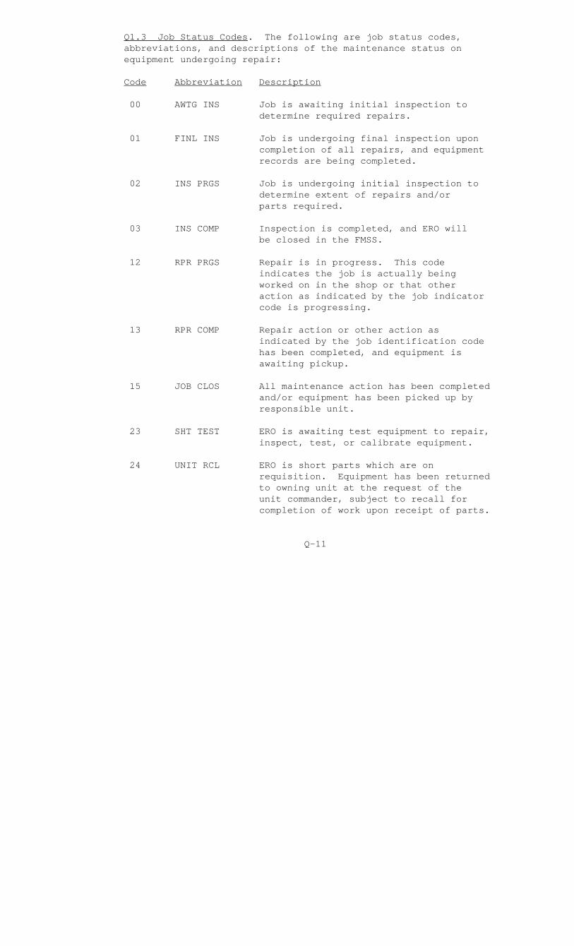
Q1.3 Job Status Codes. The following are job status codes, abbreviations, and descriptions of the maintenance status on equipment undergoing repair:
Code Abbreviation Description
00 AWTG INS Job is awaiting initial inspection to determine required repairs.
01 FINL INS Job is undergoing final inspection upon completion of all repairs, and equipment records are being completed.
02 INS PRGS Job is undergoing initial inspection to determine extent of repairs and/or parts required.
03 INS COMP Inspection is completed, and ERO will be closed in the FMSS.
12 RPR PRGS Repair is in progress. This code indicates the job is actually being worked on in the shop or that other action as indicated by the job indicator code is progressing.
13 RPR COMP Repair action or other action as indicated by the job identification code has been completed, and equipment is awaiting pickup.
15 JOB CLOS All maintenance action has been completed and/or equipment has been picked up by responsible unit.
23 SHT TEST ERO is awaiting test equipment to repair, inspect, test, or calibrate equipment.
24 UNIT RCL ERO is short parts which are on requisition. Equipment has been returned to owning unit at the request of the unit commander, subject to recall for completion of work upon receipt of parts.
Q-11
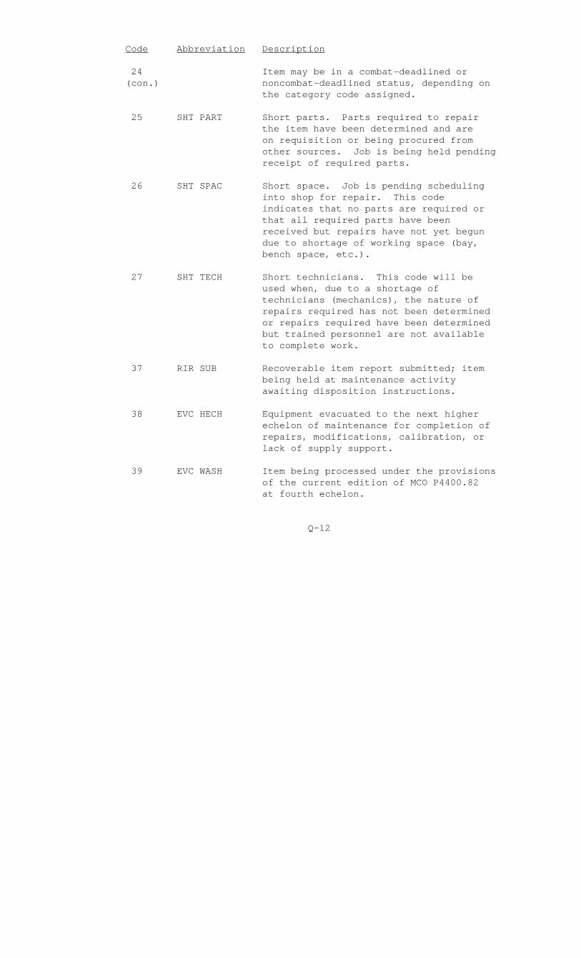
Code Abbreviation Description
24 Item may be in a combat-deadlined or (con.) noncombat-deadlined status, depending on the category code assigned.
25 SHT PART Short parts. Parts required to repair the item have been determined and are on requisition or being procured from other sources. Job is being held pending receipt of required parts.
26 SHT SPAC Short space. Job is pending scheduling into shop for repair. This code indicates that no parts are required or that all required parts have been received but repairs have not yet begun due to shortage of working space (bay, bench space, etc.).
27 SHT TECH Short technicians. This code will be used when, due to a shortage of technicians (mechanics), the nature of repairs required has not been determined or repairs required have been determined but trained personnel are not available to complete work.
37 RIR SUB Recoverable item report submitted; item being held at maintenance activity awaiting disposition instructions.
38 EVC HECH Equipment evacuated to the next higher echelon of maintenance for completion of repairs, modifications, calibration, or lack of supply support.
39 EVC WASH Item being processed under the provisions of the current edition of MCO P4400.82 at fourth echelon.
Q-12

Code Abbreviation Description
40 SHT FUND Short funds. This code will be used when, due to a shortage of funds, repair parts or labor costs cannot be obligated to complete repairs.
Q-13
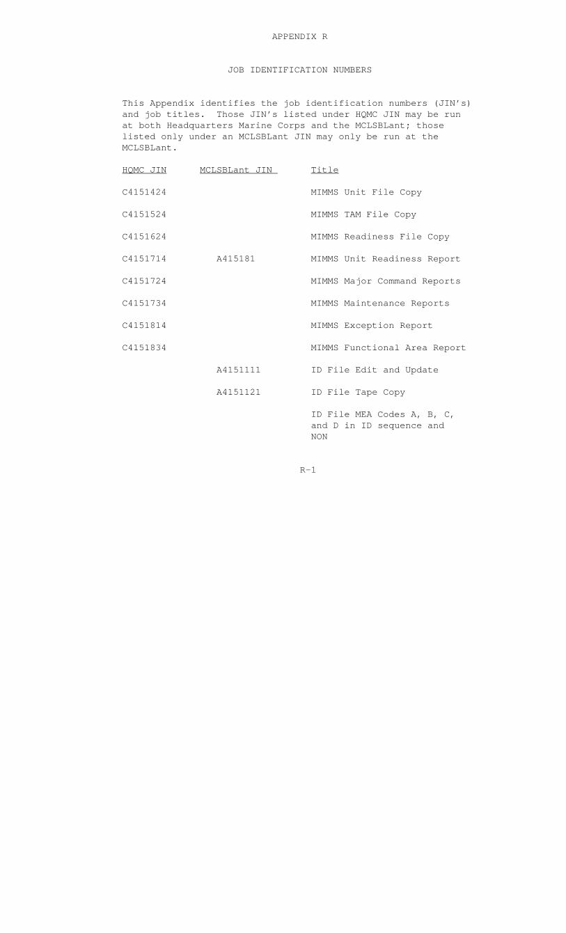
APPENDIX R
JOB IDENTIFICATION NUMBERS
This Appendix identifies the job identification numbers (JIN’s) and job titles. Those JIN’s listed under HQMC JIN may be run at both Headquarters Marine Corps and the MCLSBLant; those listed only under an MCLSBLant JIN may only be run at the MCLSBLant.
HQMC JIN MCLSBLant JIN Title
C4151424 MIMMS Unit File Copy
C4151524 MIMMS TAM File Copy
C4151624 MIMMS Readiness File Copy
C4151714 A415181 MIMMS Unit Readiness Report
C4151724 MIMMS Major Command Reports
C4151734 MIMMS Maintenance Reports
C4151814 MIMMS Exception Report
C4151834 MIMMS Functional Area Report
A4151111 ID File Edit and Update
A4151121 ID File Tape Copy
ID File MEA Codes A, B, C, and D in ID sequence and NON
R-1

APPENDIX S
MIMMS DOCUMENT STATUS FILE
This Appendix lists the data elements resident on the MIMMS document status file. Appendix C contains the associated data element label and field structure, as well as a definition for the data element.
Data Elements
Document Identifier Code
NSN
Status Date
Weapon Systems Code
Owner UIC
NORS Indicator
Document Number
TAMCN
ID Number
Serial Number
Quantity
Priority
Status
Type Status
Last Known Holder RIC
Advice Code
Job Status Code
S-1