Department of the Interior U.S. Geological Survey = Mean square error (standard deviation) in height...
29
Department of the Interior U.S. Geological Survey SET-UP MANUAL FOR ORIENTING STEREO MODELS OF AERIAL PHOTOGRAPHS ON THE KERN P62 PHOTOGRAMMETRIC PLOTTER Norman G. Banks U.S. Geological Survey Hawaiian Volcano Observatory Hawaii National Park, HI 96718-0051 Open-File Report 82-985 1982 This report is preliminary and has not reviewed for conformity with U. S. Geological Survey editorial standards. Any use of trade names is for descriptive purposes only and does not imply endorsement by the USGS
Transcript of Department of the Interior U.S. Geological Survey = Mean square error (standard deviation) in height...
Department of the Interior U.S. Geological Survey
SET-UP MANUAL FOR ORIENTING STEREO MODELS OF AERIAL PHOTOGRAPHS ON THE
KERN P62 PHOTOGRAMMETRIC PLOTTER
Norman G. Banks U.S. Geological Survey
Hawaiian Volcano Observatory Hawaii National Park, HI 96718-0051
Open-File Report 82-985
1982
This report is preliminary and has not reviewed for conformitywith U. S. Geological Survey editorial standards.
Any use of trade names is for descriptive purposes only and does not imply endorsement by the USGS
INTRODUCTION
This manual describes the step-by-step procedure required to set up a level, cleared (distortion free) stereo model on the Kern PG-2 Photogrammetric Plotter. It is intended to be used AFTER the user has been taken through the procedure at least once by a qualified user. For the more experienced user, Appendix A includes a list of reminders of the set-up procedure, an example of a worksheet that will allow rapid restablishment of old models, a list of common geologic uses of the PG-2, and a list of standard maintenance. More advanced corrections and techniques, such as water models and corrections for the curvature of the earth are not treated in this manual.
DEFINITIONS
Mp = Photoscale, e.g. 1:35,000 Mm = Modelscale, e.g. 1:31,250 Mk = Mapscale, e.g. 1:25,000 C = Plotting principal distance Cx = x-component of C Cy = y-component of C FL = Focal length of the taking camera H = Flying height above sea level Hm = Flying height above mean terrain level h = Elevation measured in the model ht = Elevation measured in the terrain (on the map) Zm = Mean projection distance in the model n = Ratio of enlargement from the model to the map mh = Mean square error (standard deviation) in height mp = Mean square error (standard deviation) in planimetry
= Swing of the plate carrier around the principal point = Tilt around the y- axis
x = x- component of y = y- component of
= Tilt around the x- axis x = x- component of y = y- component of
o = Common tilt around y- axis (expressed in o/oo) = Common tilt around x- axis (expressed in o/oo)
Bx = Base setting at the base carriage B0 = Inclination of the base bar with respect to the base carriage.
This element is used as one of the elements for relative orientation (similar to bz).
A = Variable armlength of the height counterI = Value in meters or feet of the smallest interval at the height
counter
RULES, REGULATIONS, DO'S AND DON'TS
1. Wash hands before touching the glass plates.
2. Always cover the instrument when not in use.
3. No food or drink on the instrument.
4. Lock base carriage in the center of the table after use.
5. Don't EVER use lubricants on any part of instrument OTHER than wax on the base carriage table.
6. No smoking in the PG-2 room.
7. NEVER MOVE THE PANTOGRAPH OR WORKING ARM SLIDE when the Working Arm pin is inserted in the Working Arm.
FIRST STEP INSTRUCTIONS
1. Get a qualified user to point out and name all of the parts and adjustments on the PG-2.
2. Turn on the toggle (main) switch on left side of the upper frame (fig. 1-a).
3. Adjust eye focus (fig. 2-a) and squint controls (fig. 2b, c) so that the floating mark is adjusted to your eyes. The rheostats and selector knob for the floating mark are shown in Figure 1-g, and i. If this is the first time you set up, delay this adjustment until Step 11 when both photographic plates are removed from the top of the instrument. These squint control positions may be marked on a photograph of the aluminum plates by the control knobs for your convenience in subsequent work.
4. Check and adjust all scale setting knobs on the plotter to their respective zeros (figs. 3, 4, and 9):
Kappa 2 = X 2 =300Kappa 1 = )\i =300B common Phi = Bx = 0Phi y,x = ^ y2 , ^ x2 = 200Omega y,x = ^yl , wxl = 100Common Omega = si = 0Common Phi = T = 0Bx Bx 80
5. If paper prints are to be used, make sure the gray rheostat box behind the pencil sharpener (fig. 1-b), on left side of table is plugged into the proper receptacle in the white converter box.
6. Read the focal length ( FL ) of the photographs of your stereo pair. Set Cy^, Cy£, C x ^, and C x£ to this focal length (fig. 3-a, b, c, d). If you do not know the FL of your photos, assume it is 152.5 cm; most photos are from 6 inch cameras.
7. Determine and RECORD the scale of your photos ( M p ). Do this by:
Distancea.R in mm on your base map x y\k ( a ) Distance/\_B in mm on your photographs
or ( b ) H (in feet) - Hm (in feet) x 304.8FL
8. Determine the value b using the following precedure
(a) Overlap the photos so that the image along one edge parallel to the flight line matches the image on the underlying photo. Offset the photos slightly perpendicular to the flight line and measure in mm the distance between the center ( or the two closest edge ) fiducial marks of the overlying and underlying photos.
(b) Repeat step (a) on the other edge of the photo graphs.
(c) Compute the average of the two numbers; this is b.
(d) RECORD b.
9. Locate the area on your base map covered by your stereo model. Arrange your base map on the pantograph table so that the flight line of the photos goes right to left or visa versa. Choice of which is right or left depends on getting the center of the stereo model (just located on base map) as close to the center of the pantograph working range as possible.
NOTE: If you are doing several models in sequence along the flight line, your trailing photo of the model you just set up is now your lead photo. Thus, you can eliminate the fiducial line-up for this photo and can simply move the plate to the other side of the PG-2. IF THIS IS THE CASE, for each stereo model you must determine and record b and Mp, and locate and lightly mark the location and orientation of each model on your map prior to placing the first model in the PG-2 (Steps 7, 8, and 9).
10. Set the photos on the base map as if you were going to observe them in stereo, making sure that the left and right photos are in the correct position with respect to L and R of the base map. Note which photo is left and which is right. Flip each photo face down without rotating the photos or changing their L-R sequence. The photos are now in the correct postion for placement in the plates. Without changing orientation, place each photo face down on the respective L and R plates of the PG-2 (still in place on the plotter).
11. Walk to the back of PG-2 and swing the fluorescent lights away from the plates (fig. 3-e). Carefully lift the L plate (fig. 3-f, g) from the instrument while maintaining the photo in its correct postion. Place the plate on a light table. (If this is the first set up of the flight line, remove both plates now and adjust squint controls as noted in Step 3 above.) Lift off the photo and place it by the plate without changing its orientation relative to the plate.
12. Carefully slide the four clips (fig. 3-h) from the pressure plate (fig. 3-g). Carefully lift the pressure plate off of the optical plate (fig. 3-f), and set pressure plate on a soft surface (notepad). Place the photo on the optical plate without changing its orientation and replace the pressure plate (center ed over the photo). Slide the photo and pressure plate until the corner and center fiducial lines engraved in the optical plate approximately match the respective marks on the photo. Carefully slide two opposing clips onto'edges of the pressure plate. If your photos are transparencies adjust the plate fiducials and photo fiducials to the best fit, using the 4 microscopes in the PG-2 tool box. If your photos are paper prints, carefully turn the plates so that the optical plate rather than the pressure plate is up and adjust your fiducials as above. When satisfied with the fit, engage the remaining 2 clips.
13. Go to the PG-2. Check the filters to see whether the clear (for color photos) or green (for black and white photos) filters are over the viewing column, visable now below the optical plate support frame (fig. 3-i). Make change if necessary (the filters are in the tool box). Return to the light table, pick up the plate by its knobs, and gently replace it on the PG-2 (it only goes one way, three feet in 3 cradles).
14. Repeat the 11 through 13 for your right photo. Swing the fluorescent lights back over photos.
15. COLLAPSE THE MICROSCOPES AND REPLACE THEM IN THE TOOL BOX.
16. If the model is a transparency, start the fluorescent lamps by depressing the button on the left side of the upper frame for a few second and then releasing it (fig. 1-c); adjust the light level with the rheostats (fig. 1-h) on the upper frame of the PG-2. If the model is paper print, adjust the light level with the rheostats on the gray box behind the pencil sharpener (fig. 1-b).
PANTOGRAPH SET-UP
Definitions: Mk = scale of base mapMp = scale of photoMm = scale of PG-2 model
Note: Mp may not exceed Mk by 5X or be smaller than 0.5 Mk.
1. Go to pages E through L of PG-2 tables (0.005 mm dial gauge feet). Note that the format for reading this table is in the upper right corner of each page. Find the proper column with bold type equivalent to Mk. Go down the column until you find the model scale Mm closest to Mp. RECORD THIS Mm. (If you cannot find the proper Mk, go to SPECIAL PROCEDURE 1 (at the end of this section). IF ALTEK IS AVAILABLE, SKIP THIS STEP, AND GO TO SPECIAL PROCEEDURE 2 (at the end of this section).
2. Still using the table format in upper right of page, find and RECORD I. I is the distance in feet for each interval of the Z column dial gauge. IF ALTEK IS AVAILABLE, SKIP THIS STEP.
Also, RECORD A. This is the arm-length, set this number on the black arm-length dial gauge on the right of base carraige behind the Z gauge (fig. 4-a). The aluminum case around the gauge flips up to allow this adjustment. The coarse A scale is shown in Figure 4-b.
3. Obtaining the proper Z column distance.
NOTE: The locking marks (fig. 5-c) on the frame supports (fig. 1-d, 5-b) are roughly equal to focal length of the camera used. For photographs with FL = 152 mm, the settings at sea level are 152. For a given focal length the frame must be 1 owered for high terrain and raised for low terrain. For 88 mm photographs lower the frame below lowest locking grove (resting on the safety lock).
(a) Move the base carriage to the center of the table and try to get your model in focus and the floating dot on the ground at magnification 2X. If this is your first or second time you have tried to set up a model on the PG-2, the parallax of your model may make this seem an
imposibility. However, after a little practice, you can judge whether the problem is parallax or improper Z column distance. In the cases where you are unable to obtain approximate focus on the model and cannot get the dot on the ground, get the closest approximation, then observe the Z column cylinder (fig. 4-c).
(b) If you are at the proper Z column locking mark, and the Z column (fig. 4-c) is all the way out of its sleeve, you must lower the upper frame of the PG-2 (fig. 1-e); go to step 3c. If the Z column is all the way down, the frame it must be moved up; go to step 3g.
(c) Lock the base carraige at the center of the table (fig. 5-a). Unloosen and back off the thumb screw (fig. 5-d) on one of the upper frame supports (There are two upper frame supports at the front and one at the rear of the PG-2). Depress the palm latch (fig. 5-e) with your palm while maintaining a firm hold on the frame. The supports are spring loaded so the effort in holding and moving the frame is small. HOWEVER, do everything gently so that the frame is not jarred. With the palm latch de pressed, move the frame down until it seats in the next ring 10mm down. Never go more than 10mm on one support without doing step 3d. RETIGHTEN the thumb screw firmly (but don't crank it down).
(d) Repeat (c) at the other two stations.
(e) Repeat (c) and (d) until the model clears, then repeat (c) and (d) two more times (20 mm more in two steps).
(f) Make sure all the thumb screws are firmly tightened.
(g) Lock the base carriage as above. Do steps b through e but in the opposite direction ie. raise the upper frame in 10mm steps.
4. Unlock the base carriage. Move the Z column with the Z wheel, (fig. 4-d), until it is almost all the way down in its sleeve with the red dot at the top of the column resting at the top of the sleeve. Index the black mark on the Z wheel with the black arrow on the base carriage at the 8 o'clock position on the wheel frame (fig 4-e). Zero the Z gauge (fig. 4-f) with the knurled data setting knob (fig. 4-g) on the left side of the Z column (fine adjust by rotating the gauge face).
5. Move the Z column up using the Z wheel until the lower red dot rests on top of the sleeve. Index as before and read the Z
gauge. The value should agree within 1 or 2 gauge units with the value (h) in the upper right compartment of the tables at your chosen Mm and Mk. If it does not agree, there has been an error in indexing. Repeat Steps 4 and 5 to check whether this was the case. If no error was made, call a qualified technician or KERN.
6. Go to the far right column of the KERN tables on the row of your selected Mm; read and RECORD the n value. This is the number of the transmission disc needed to scale your pantograph. IF ALTECK IS AVAILABLE, REFER TO SPECIAL PROCEDURE 2 (at the end of this section).
7. Lock the base carriage at the back center of the table (fig. 5-a). Loosen and remove the screw (fig. 6-b) that locks the Jackson Arm (fig. 6-b) to the Working Arm (fig. 6-c) CAREFULLY discon nect the Jackson Arm from the Working Arm. In other words, do not jerk it off thereby applying torque to the Working Arm. Instead, use thumbs and hands as opposing levers to support the Working Arm while disconnecting. After disconnecting, make sure that the Working Arm Slide (fig. 6-d) is free to slide on the arm.
8. CAREFULLY (DO NOT CAUSE INSTANTANEOUS RELEASE) release tension on the the Pen Arm transmission band (fig. 6-f). Do this by grasping with the left hand the knob on the tension ratchet to the right of the pen (fig. 6-g) brace the hand and slowly turn knob counter-clockwise while pushing the locking lever (fig. 6-h) towards the arm, taking up the spring tension with your left hand on the knob. After releasing the ratchet in this manner, keep the locking lever disengaged and release the tension on the band by clockwise rotation of the black knob. Loosen the band enough so that it will slip up over the trans mission disc knob (fig. 6-j) at the left end of the left Pen Arm. Lay the band toward the center of the pantograph table. NEVER KINK THE BAND.
9. CAREFULLY unloosen the transmission disc knob (fig. 6-j). Remove the transmission disc (fig. 6-k) and exchange it with the one in the tool box having the n value recorded in step 6.
NOTE: If your Mm is <.8 and >.5 your Mp, see SPECIAL PROCEDURE 3 (at the end of this section).
10. Place the new tranmission disc in place; replace and tighten the transmission disc knob firmly but not too firmly. Replace the band over the disc - WITH CAUTION NOT TO KINK IT and on the back sides of the two drums to the right of the disc (fig. 6-1).
11. Rarely snug the band with counterclockwise rotation of the ten sion knob described in 8. Make sure that the band is seated properly in the drums and on the transmission disc. If not, release the tension and try again.
12. There is an indexing pin hole on top of and to the right of each number on the Working Arm (fig. 6-m). The numbers are ranges of n values. Move the Working Arm Slide to the n value range that fits the n value recorded at step 6. Insert the pin (fig. 6-t) on the Slide into the index hole in the arm at this n value range. NEVER, NEVER BUMP OR ATTEMPT TO MOVE THE BASE CARRIAGE, WORKING ARM SLIDE, OR PANTOGRAPH ARM WHEN THE WORKING ARM PIN IS DOWN!!!
13. Move the Pen Arm Slide (fig. 6-s) so that the black index arrow (fig. 6-r) lines up with the n value of transmission disc (see step 6). Tighten the Pen Arm band tension knob until the ratchet ceases to click. Fine adjust the n value index on the Pen Arm Slide with small wheel to the left of index arrow (fig. 6-n). LIFT THE PIN ON WORKING ARM SLIDE FROM ITS INDEX HOLE.
14. After lifting the pin, slide the Working Arm Slide up and down the working arm a few times. Return the Slide to index with proper n value range and re-insert the pin.
15. REREAD the Pen Arm index to see if it is still centered on the correct n value. Fine adjust with wheel on the Pen Slide if necessary. DISENGAGE the pin on Working Arm Slide.
16. Unlock the base carraige and bring the Jackson Arm within working distance. REMOVE the two thumb screws (fig. 6-0) holding the top part of the Jackson Arm. Adjust the arm to index with the n value for your model (step 6). Replace and tighten firmly the thumb screws on the Jackson Arm.
NOTE: If you position the index on the Jackson Arm near to the value of the transmission disc, it will center your work area on the pantograph table. To shift work area to right, place Jackson Arm at lower index value to move work are to left, place at higher index value. Changing the length of the Jackson Arm does not effect scale - it only shifts the plotting area on the Pantograph table.
17. Using the base carriage, reposition the Jackson Arm near the Working Arm. Reattach the Jackson Arm to the Working Arm Slide. AGAIN, do not put pressure directly on the Working Arm; support the slide with your fingers and press down on the Jackson Arm attachment with the thumbs until it seats. Replace the locking screw and tighten fingertight only.
18. Compute and record the value g v = P v ^
Set this on the Bx scale (upper left gauge on base carriage; fig.
19. Continue special procedures here or proceed to REMOVAL OF PARALLAX.
Special Procedure 1
(a) If you do not find Mk in the KERN tables = your Mk, see if you can find a column in the tables with jf 10 x (or 100X, 1000X, etc.) of your Mk. Then use all the inform ation in the table EXCEPT I. Compute I by multiplying or dividing I in multiples of 10 in the same manner as required to convert your Mk to the Mk in the tables.
(b) If the proper Mk or Mk equivalent 4- 10X (or 100X, 1000X, etc.) is not found in the tables, compute your own table by use of the formulas on p. 9 of the PG-2 instruc tion manual.
Special Procedure 2
If ALTEK (digital electronic height counter) is available,
(a) Compute and record:
n = transmission disc nearest to n'
Mm = Mk x n
(b) Set ALTEK scale to Mm x 0.05 (if metric)Mm x 0.1640435 (if english)
Special Procedure 3
(a) Put the old transmission disc in the tool box. Replace the band over the center post that normally takes the transmission disc. Do this in the manner described in step 10, then do step 11.
(b) For step 12, insert: move the Working Arm Slide to stop at the far end of the arm and hold it there with your left hand. MAKE SURE YOU DO NOT SWING THE PANTOGRAPH ARM DURING THIS PROCEDURE.
10
(c) For step 13, insert: set and index the Pen Arm Slide at 2.0, and tighten the band as in 13.
(d) For step 14, insert: release your hold on Working Arm Slide. Move the Working Arm Slide up and down the arm several times. Return the Slide to farthest end of arm and hold it there with your left hand.
(e) Do step 15 (MAKE SURE YOU DO NOT SWING THE PANTOGRAPH DURING THIS PROCEDURE) for n value = 2.0 and then release your hold on the Working Arm Slide.
(f) For step 16, insert: place Jackson Arm at maximum exten sion.
(g) Proceed through steps 17 - 19.
REMOVAL OF PARALLAX
1. Recheck 0 positions of fy2, If x2» B$» COyl» (Jxl» A » and I-
(See step 1 of FIRST STEP INSTRUCTIONS)
2. Set the base carriage to Position 1 (fig. 7). This will be with the n-gauge scale = 0 (fig. 3-j), and the Cxj slide bar (fig. 3-c) in the vertical position (bar parallel to the gauge). Focus the dot on ground by using the K2 gauge (fig. 3-k) in concert with the Z wheel (fig. 4-d) to bring the image at the center of the field into stereo alignment while forming one spot focused on the ground. Consult Figure 7 for determin ing how the dots should move relative to each other. Begin this process at 2x magnification and do the final clearing at 8x. Normally, it will be impossible to obtain stereo for the whole field of view, so concentrate on the immediate center of the model.
NOTE: If there is extreme parallax in the model, it may be difficult to obtain stereo even in the center of the model. In this case, get the best alignment possible and go to step 3.
3. Repeat step 2 at Position 2 (fig. 7) using the >^ } gauge (fig. 3-1). Position 2 is obtained with the base carriage on the right center of the base carriage table (n=0) and the Cx2 slide bar (fig. 3-d) in the vertical position (parallel to its gauge). If stereo was difficult to obtain in step 2, return to step 2. If adequate stereo and placement of the dot on the to step 5.
11ground was achieved in both steps 2 and 3 go to step 6. In very rare cases, satisfactory stereo will still not be achieved after two iterations of steps 2 and 3. If so, go to steps 4 and 5.
Return to positioning of step 2 and determining whether theH2 9 au 9 e ( fi 9- 3 ' 1 ) is a11 tne way Past 290 ° or 310 °- Go to the back of the instrument, swing the fluorescent lights away from right hand plate ( ft 3)- Note tne center of the photo and carefully remove the clips from the pressure plate, lift off the pressure plate without disturbing the photo, place a finger at center of photo, rotate the photo about its center (under your finger) to achieve about 10° more rotation in the direction already traveled by Y\ 2-
Replace the pressure plate and clips without disturbing the photo. Swing the fluorescent light back. Proceed with steps 2 and 3. If you achieve adequate stereo on both ft i and ft 2 go to step 6: if not (after two iterations of 2 and 3) go
5. Repeat step 4, only this time with ^i(left) photo. Again, do steps 2 and 3. If the photos do not achieve stereo now, you have done everything possible and the plane turned 90° between exposing the two photos. Ask for a refund on your photography. If stereo is achieved, go to step 6.
6. Move the base carriage to point 3 (Position 3 of fig. 7,slide bar vertical (fig. 3-d) and the n-scale at some uneven integer. For 1 52 mm (6 inch) cameras, n =3 is the most conven ient position for proper coverage and later calculations. Adjust B o gauge (fig, 4-k) and Z wheel as above until stereo is achieved and the dot is on the ground. In cases where stereo still is not achieved before the Bo adjustment range is exceeded, you have to begin all over again at step 1 of this section after placing the right photo in the left plate and vice versa. If you have achieved stereo, proceed to step 7.
7. Move the base carriage to the left rear of table (Position 4, fig. 7) so that the Cx^ slide bar (fig. 3-c) is vertical and the n-scale is on the same number as in Position 3. Remove parallax as in the above steps using the *fy2 gauge (fig. 4-p) and the Z wheel. When stereo is achieved and the dot is on the ground, read the ^y2 If it exceeds +; 1.25 units from its zero position of 200, use the tables on the 5 Y2 arm rest (fig. 1-f) to obtain the required correction for Cy2 (fig. 3-b). Dial the proper correction into Cy2 transfer the read ing on *$ y2 to the ^ X2 (fig. 3-m) gauge. Go to step 8.
8. Move the base carriage to the front center of table (pen switch indexed with the screw on the center front of the table and the n-scale = the setting used in steps 6 and 7 but on the other
12
9.
10.
side of n = 0 (Position 5, fig. 7). Remove parallax as in prev ious steps using the u;y^ gauge (fig. 3-n). Read and record (jjyi, and if your n-scale setting was 3, move the gauge an equal amount in the same direction to the correction already made. (Remember that the 0 position for CJyi was 100). The number of times this over correction should be made is determined by the formula 1/2 x (n-1). In most cases you will have used n = 3, hence you make one 1/2 x (3-1) over-correction. Transfer this total correction to the CJx^ gauge (fig. 3-o). If the total correction exceeds _+ 1.25 units from 100, find the correc tion factor required for Cxj gauge (fig. 3-c) from the tables on the \f y2 arm rest. Dial this correction into Cx^. Go to step 9.
Repeat steps 2, 3, 6, and 7. Go to step 10.
Go to Position 5 and determine WITHOUT TOUCHING the (jyi GAUGE whether any parallax remains. If less than one floating dot diameter of parallax remains, go to SCALING. If more, go to step 9.
1.
2.
3.
4.
5.
6.
Recheck indexing of of PANTOGRAPH SET slide.
SCALING
pantograph (repeat UP). Sharpen the
steps 7, 12, 15, and 17, pencil and reinsert pen
Find, using your base carriage and Z wheel, two points (A and B) as far away as possible on your that are also well defined on your base map.
well-defined stereo model
Move to Point A on your photo on the ground over the point. that you are still over and relock as necessary.
model and carefully place the dotLOCK the base carriage and check
on Point A. Unlock, adjust, and
Move Point A on base map under the pantograph pencil. You can either use the solenoid to place the pencil on the map or place the pencil point in the scaled measurement disc (from the tool box) and position point A of the map under 0 on the disc. Weight your map, making sure the weights will not interfer with the pencil or Working Arm Slides. Recheck that step 3 is still satisfied.
Unlock the base carriage. Move the dot to Point B and carefully place the dot on ground over point B. Lock the base carriage. Place a finger on Point A, remove weights and rotate the map so that point B on the map is on a line with point A and the position of the pencil. Reweight the base map.
Measure and RECORD distance AB (L) on the base map. Measure the distance _+ L that the pencil is too far beyond or too short of point B on the map.
13
x BX (old) Note: Bx(old) is 80 unless reset earlier.
Calculate:
Bx (new) = Bx (old) _+ ABx
Change dial Bx to Bx (new) (fig. 4-k).
8. Repeat steps 3-7 until A and B of the stereo model and the map exactly coincide. Observe the entire model for parallax. If you have more than one dot separation of parallax, return to REMOVAL OF PARALLAX and do steps 2,3,6,7,8,9, and 10 untilparallax is removed. Go to step 9 if or when the worst parallaxis smaller than one dot separation.
9. Check several more points (3 to 5) to see if points on the map and the stereo model coincide satisfactorily over the entire model. If they do, proceed to LEVELING. If not, it is probable that either point A or B were mislocated during construction of the base map. Choose two new points (C and D) and repeat steps 3-9 (using points C and D). Repeat step 9 with the new points until a satisfactory fit of the photo and the map is achieved over the entire model. In rare cases this is not possible and is the result of uneven stretching of the photos, map, or both. If so, (1) get the best approximation, or (2) make your own topo base map with the PG-2.
LEVELING
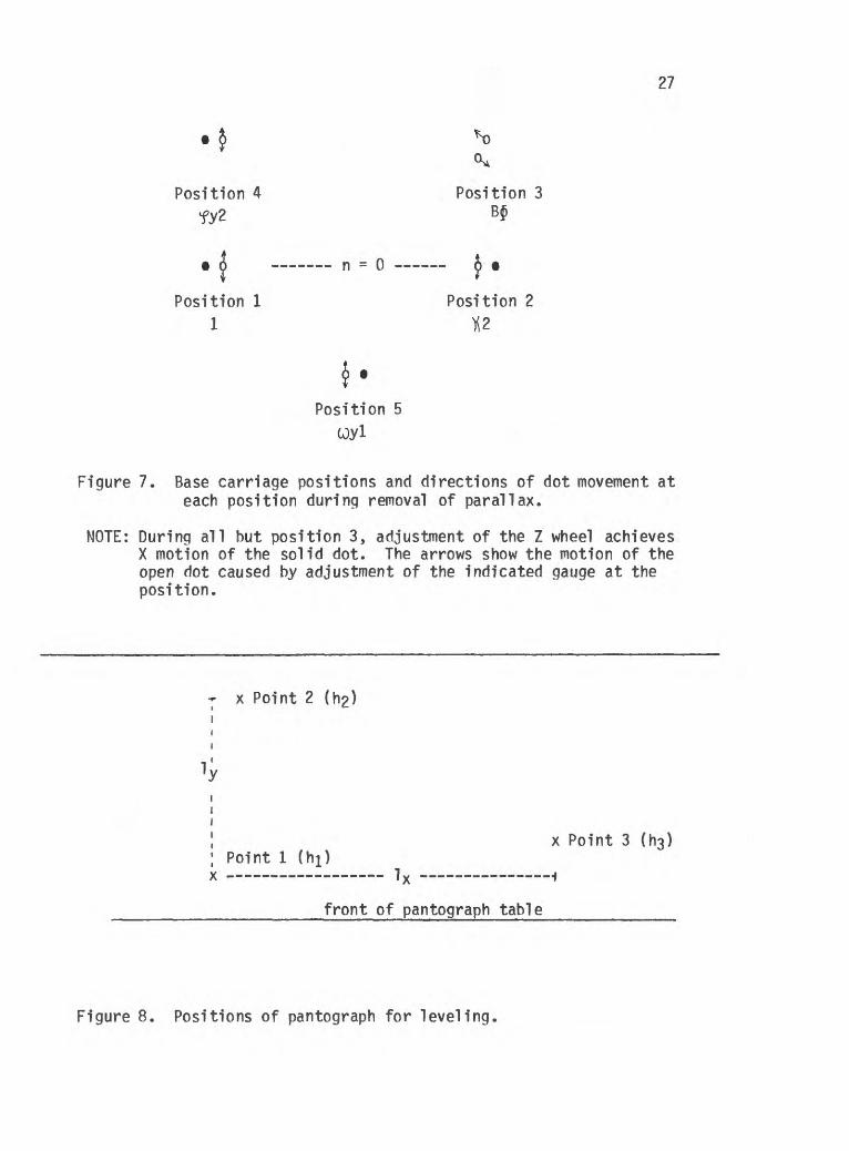
1. Choose 3 positions as shown in Figure 8. Each position must be well defined on both base map and photos, should have readable elevations on the base map, and should be as far away from each other as possible. Points 1 and 3 should be as close to parallel with the front edge of the pantograph table as pos sible. The line Point 1 -Point 2 should be as near to perpen dicular to the front edge of the table as possible. As shown in Figure 8, rather than the actual distances between the points, the distances Ix and ly are measured from Point 1 along lines parallel and perpendicular to the front of panto graph table.
2. Move the dot with the base carriage and 2 wheel to Point 1 and set the dot on the point. Using the knurled knob (fig. 4-g) and dial face (fig. 4-f), set the 2 dial to the elevation indicated for Point 1 on the base map. If you can not reach this elevation, add multiples of 1,000 feet to the map elevation until you can set the modified elevation on the dial. Remember, to get the dial elevation, you must refer to I (recorded earlier) to calculate the number of feet per dial gauge interval (I).
IF ALTEK IS AVAILABLE, SET THE ALTEK preset value to the eleva-
14
tion for Point 1 on the base map.
3. Move to Point 2. Set dot on the ground over the point. Read the 2 dial. If it does not read the correct elevation for the point (with the appropriate thousands added), calculate as follows the Aftcorrection.
1000
Any is in feet, hence ly must be measured (or converted) to feet.
/^h is dial h - map h (i.e., if map h > dial h, 4h is -).
4. Loosen the thumb screw of gauge by your left knee and make ad justment (black for +, red for -) using the gauge (fig. 9a,b)
5. Return to Point 1. Repeat steps 2-4 until the dial gauge at Point 2 reads 1 or 2 units of what it should read. Tighten thumb screw on the J\. gauge.
6. When satisfied, move to point 3 and repeat steps 3-5 using points 1 and 3 to make $5 corrections where &f = ^x x 1000. The
f gauge is by your right knee (Fig. 9-c, e). The thumbscrew (fig. 9-d) is to the left of the main gauge, the thumbscrew behind the leg only adjusts tension on the gauge). EACH TIME you make a 4£ correction, you must introduce the same correction (in value and +_ sense) to the scaling B J gauge (fig. 4k). Alternatively, you can repeat step 6 of REMOVAL OF PARALLAX.
7. Check points 1-3 to ensure that they all read within +_ 1-2 dial gauge units of their actual value, check other points on the model until you are satisfied the model in level. If not satisfied, choose 3 new points and repeat steps 1-7.
8. Return to and repeat REMOVAL OF PARALLAX, SCALING, AND LEVELING to fine tune the model. For construction of topographic maps you reiterate this fine tuning until all parallax is removed, all points fit, and all elevations read correctly.
MISCELLANEOUS ADJUSTMENTS
1. Increase pencil solenoid air cushioning by rotating the two pins on the solenoid (fig. 6-p) towards each other.
2. Adjust pencil clearance by turning knurled knob on pen solenoid (fig. 6-q).
15
APPENDIX A PG - 2 PROCEDURE OUTLINE
1. Initial Set-up.
a. Set squint correction.
b. Set plotting principal distances = Cxi, Cyi, Cx2, Cy2, = Camera focal length.
c. Calculate b from photos (ie. mean overlap),
d. Calculate Mp.
e. From Kern tables determine Mm, I, A, h, k, n (if hmeas >h-j, A = neg), A = k(h-j-hmeas ). IF ALTEK: Calculate n and ALTEK scale.
f. Set A. OUT IF ALTEK.
g. Calculate and set Bx.
h. Calibrate height dial using h, k. (not necessary unless level ing also). OUT IF ALTEK.
i. Mount photographs on glass plates
j. Install correct filters (green filters for B/W photographs; clear for color photographs).
k. Place glass plates on carriages.
2. Pantograph Set-up.
a. Select proper transmission disk.
b. Remove working arm from Jackson Arm.
c. Loosen pen arm band.
d. Replace transmission disk.
e. Loosely tighten pen arm band.
f. Set Working Arm to proper ratio position.
g. Set Pen Arm to proper ratio position.
h. Tighten Pen Arm band, fine-tune Pen Arm ratio position and free Working Arm.
i. Set Jackson Arm to proper ratio position,
j. Replace Jackson Arm onto Working Arm.
16
3. Removal of Parallax - Points to remember.
a. Zero dials as follows:Jl= 0; J = 0;£jxi = u)yi = 100;
=fy2 = 200;K! = K 2 = 300.
b. If the Z-dot cannot be put on the ground, increase or decrease the projection distance.
c. Add appropriate corrections to Tx2 .
d. Immediately transfer6Jyj reading corrections to^Jxi (including overcorrection).
e. If fy or UJ y corrections are > 1.25, make necessary corrections to Cy 2 and tx^ respectively when model is finally cleared. (always a negative correction).
4. Scaling.
a. Recheck pantograph for ratio settings.
ABx = -*l x Bx(old)
(AL is negative if model distance is too long).
b. Follow worksheet.
5. Leveling.
a. Follow worksheet.
b. Remember to make corrections to BJ after adjusting J .
c. NOTE: 1) Units of scales for SL and J are thousands.
2) One rotation of the -A, $, and Bj knobs represents 10 units.
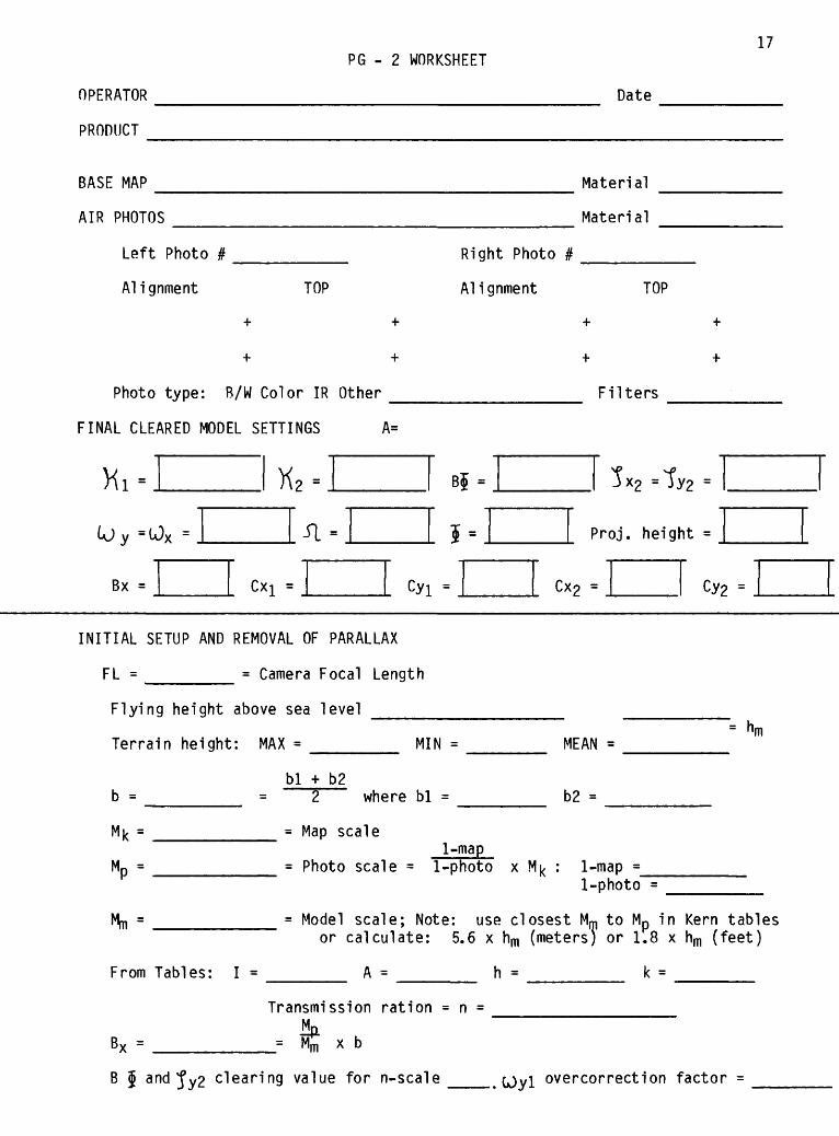
PG - 2 WORKSHEET17
OPERATOR
PRODUCT
BASE MAP
AIR PHOTOS
Left Photo #
Ali gnment
Date
TOP
Material
Material
Right Photo #
Alignment TOP
Photo type: B/W Color IR Other _
FINAL CLEARED MODEL SETTINGS A=
= U)v =
Bx = Cxj =
Filters
Proj. height =
cyi = CX2 =
INITIAL SETUP AND REMOVAL OF PARALLAX
FL = ______ = Camera Focal Length
Flying height above sea level
Terrain height:
b =
Mt =
Mp-
Mm =
MAX =
bl + b2= 2 where
= Map scale
= Photo scale =
= Model scale;
MIN =
bl =
1-map1-photo
Note: use
= nm MEAN =
b2 =
x Mfc : 1-map =1-photo =
closest Mm to Mp in Kern tablior calculate: 5.6 x hm (meters) or 1.8 x hm (feet)
From Tables: I =
BX =
A = h = k =
Transmission ration = n =
K X b'm
B J and j*y2 clearing value for n-scale ___. (Oyl overcorrection factor =
18 APPENDIX B PG-2 MAINTAINANCE
I. Cleaning
A. Base table
1. Occasionally wipe with dry cheesecloth.
2. If the base table gets very dirty (rough movement) clean its surface with lighter fluid to remove its coat of wax. Clean thoroughly with a cloth and rewax before using again.
B. Carriages
1. Wipe off dust on rails with a dry cheesecloth.
2. Clean bearings with kleenex, and then run a strip of mask ing tape over them.
3. Remove Cxl and Cy2 assemblies by lifting them straight up. This allows removal of the carriages. Clean as above.
C. Pantograph
1. Loosen the transmission band before cleaning Working Arm parts.
2. Clean rail with cheesecloth or kleenex.
3. Clean bearings by putting a q-tip on them and running the bearing along the rail.
D. Optics
1. If the immage is dim on 2x and 8x, it means the optics are di rty.
2. Clean optics with a q-tip or lens paper. DO NOT USE TOILET PAPER as it contains a substance which will destroy the coatings on the lenses.
II. Replacement or Repair
A. Pantogrpah bands
1. If the holes on the working arm band are damaged or worn, put a spacer on the spring on the pen arm side of the
19
band assembly, slip the band off the drive wheel, and rotate the sprocket one notch; reset the band, and remove the spring spacer.
2. Replace bands if necessary using the alien wrench in the accessory tool box.
B. Light bulbs
1. Dot immage bulbs are special bulbs made by Kern.
a) They are friction fit in the bulb housing.
b) Be careful not to have the bulb wire hang-up on the carriages.
2. Paper print illuminator takes GE bulb #1141 (12V). (Orig inal bulb = OSRAM 7533 12V 15W Germany).
a) To remove this bulb, clip it off of the light housing, loosen the holding screws, and remove socket and bulb through the back of the housing.
b) Replace the bulb with the filiment oriented horizontal ly.
C. Fuses - 1 on body and 3 on transformer.
APPENDIX C LIST OF USES OF PG-2
1. Transfer of geologic information and note stations from photo graphs to planimetric base map
2. Structural studies of cracks
3. Construction of topographic base maps
4. Determining line of sight for construction of geodimeter networks
5. Accurate planimetric location of benchmarks and seismic, tilt, and geodimeter stations
6. Determination of creep
7. Detailed level maps
8. Updating of topographic base maps
9. Area of lava flow, cross-section area; volumes of flows
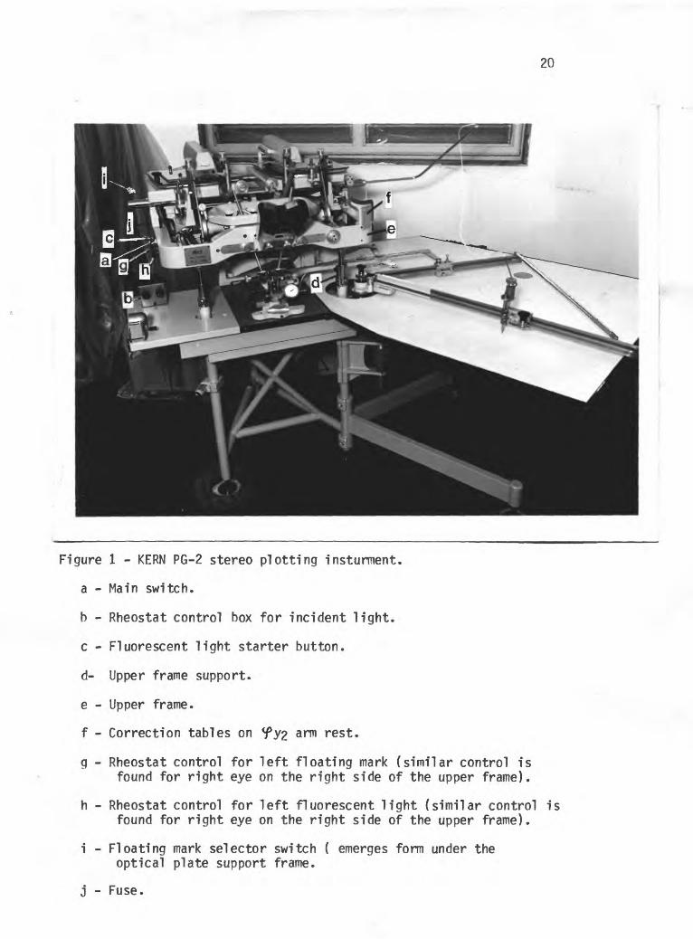
20
Figure 1 - KERN PG-2 stereo plotting insturment.
a - Main switch.
b - Rheostat control box for incident light,
c - Fluorescent light starter button,
d- Upper frame support,
e - Upper frame,
f - Correction tables on <fy2 arm rest.
g - Rheostat control for left floating mark (similar control is found for right eye on the right side of the upper frame).
h - Rheostat control for left fluorescent light (similar control is found for right eye on the right side of the upper frame).
i - Floating mark selector switch ( emerges form under the optical plate support frame.
j - Fuse.
21
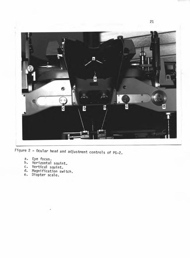
Figure 2 - Ocular head and adjustment controls of PG-2,
a. Eye focus.b. Horizontal squint.c. Vertical squint.d. Magnification switch.e. Diopter scale.
22
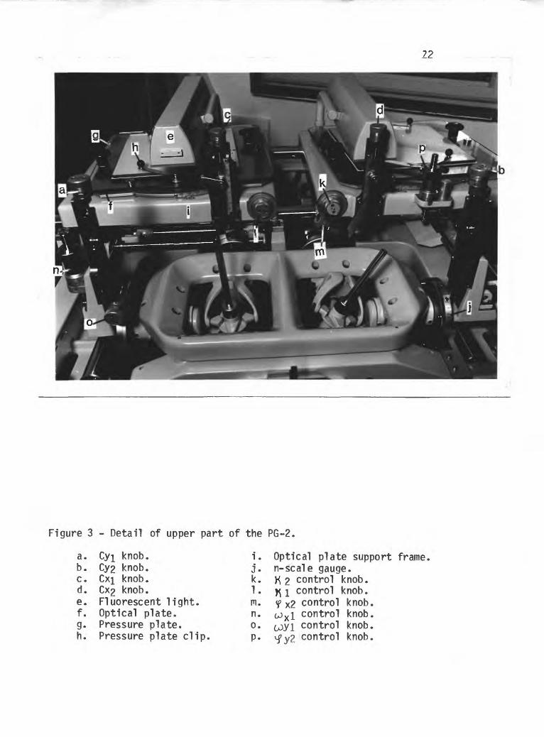
Figure 3 - Detail of upper part of the PG-2.
a. Cyj knob.b. Cy2 knob.c. Cxi knob.d. Cx2 knob.e. Fluorescent light.f. Optical plate.g. Pressure plate.h. Pressure plate clip.
i. Optical plate support frame.j. n-scale gauge.k. ft 2 control knob.1. y\ 1 control knob.m. f X2 control knob.n. GJ X I control knob.°- c^yi control knob.p. v control knob.
f- 23
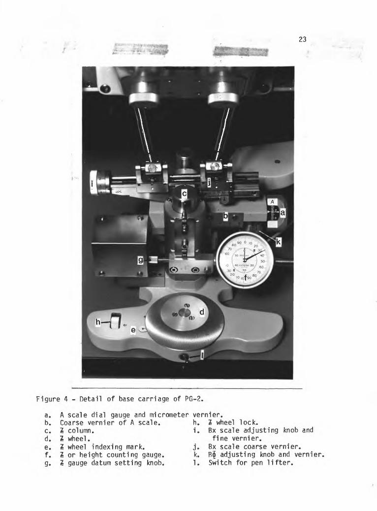
Figure 4 - Detail of base carriage of PG-2.
a. b. c. d. e. f.g-
A scale dial gauge and micrometer vernier.Coarse vernier of A scale.Z column.Z wheel.Z wheel indexing mark.Z or height counting gauge.Z gauge datum setting knob.
h. Z wheel lock.i. Bx scale adjusting knob and
fine vernier.j. Bx scale coarse vernier, k. B$ adjusting knob and vernier, 1. Switch for pen lifter.
24
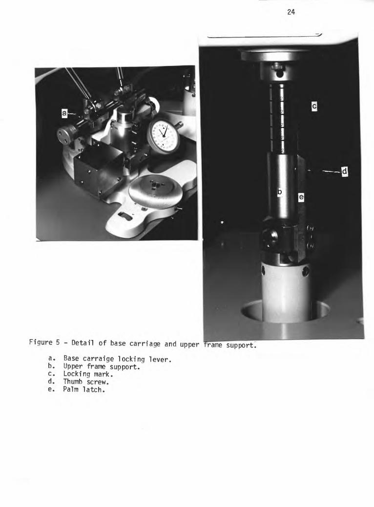
Figure 5 - Detail of base carriage and upper frariesupport
a. Base carraige locking lever, b. Upper frame support.
Locking mark.Thumb screw.Palm latch.
c. d. e.
25
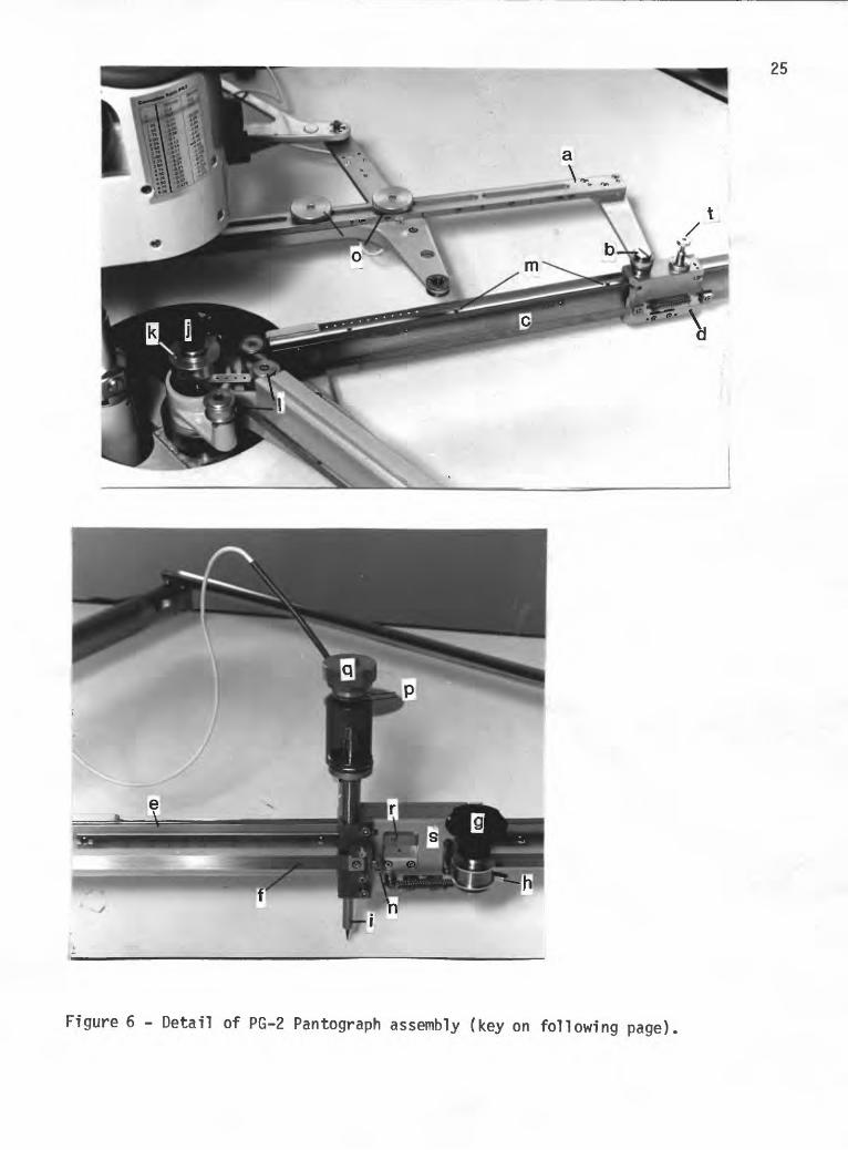
Figure 6 - Detail of PG-2 Pantograph assembly (key on following page).
26
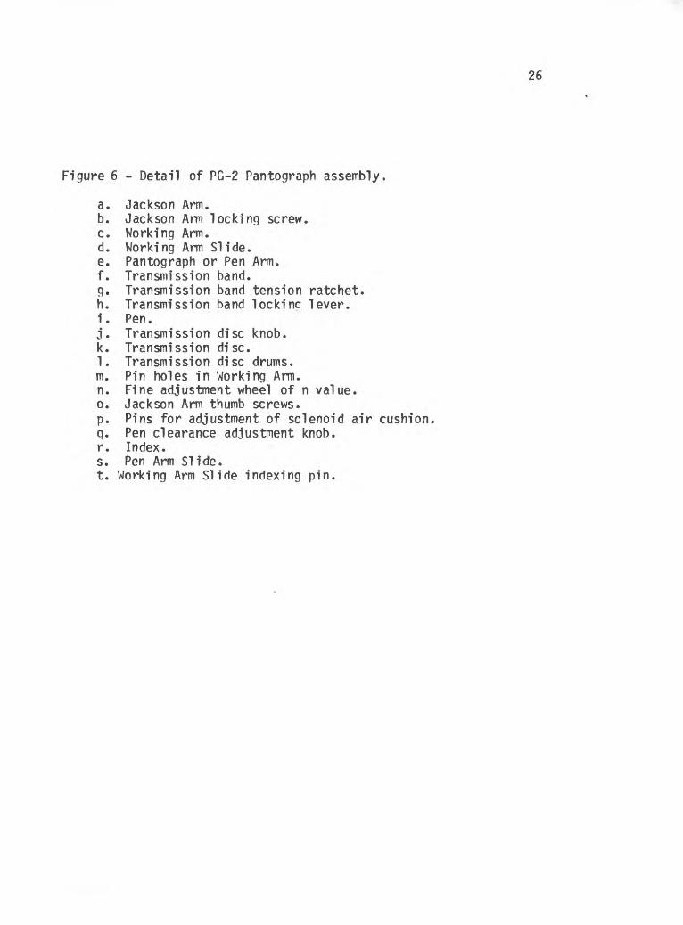
Figure 6 - Detail of PG-2 Pantograph assembly.
a. Jackson Arm.b. Jackson Arm locking screw.c. Working Arm.d. Working Arm Slide.e. Pantograph or Pen Arm.f. Transmission band.g. Transmission band tension ratchet.h. Transmission band lockinq lever.i. Pen.j. Transmission disc knob.k. Transmission disc.1. Transmission disc drums.m. Pin holes in Working Arm.n. Fine adjustment wheel of n value.o. Jackson Arm thumb screws.p. Pins for adjustment of solenoid air cushionq. Pen clearance adjustment knob.r. Index.s. Pen Arm Slide.t. Working Arm Slide indexing pin.
27
Position 4 Position 3 fy2 B£
n = 0 $ t
Position 1 Position 21 ^2
Position 5 coyi
Figure 7. Base carriage positions and directions of dot movement at each position during removal of parallax.
NOTE: During all but position 3, adjustment of the Z wheel achieves X motion of the solid dot. The arrows show the motion of the open dot caused by adjustment of the indicated gauge at the position.
T x Point 2 (ha)
! x Point 3 (113); Point 1 (hj)x l x i
________front of pantograph table_________
Figure 8. Positions of pantograph for leveling.
28
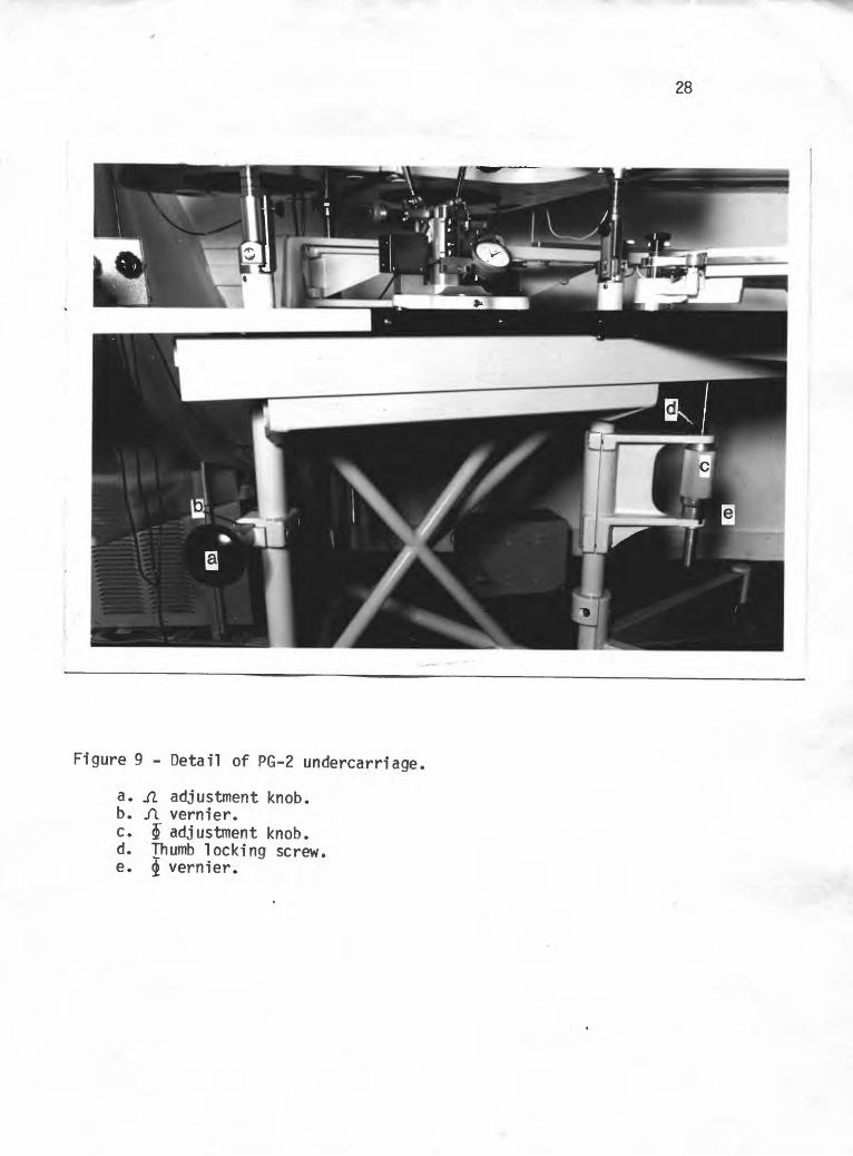
Figure 9 - Detail of PG-2 undercarriage,
a. fi adjustment knob,b. fi vernier,c. $ adjustment knob,d. Thumb locking screw,e. vernier.