DEPARTMENT OF THE ARMY TECHNICAL MANUAL(DELCO-REMY MODEL 1113943) (MILITARY PART NUMBER 10911018-1)...
110
TM 9-2-2920-242-35 DEPARTMENT OF THE ARMY TECHNICAL MANUAL DIRECT SUPPORT, GENERAL SUPPORT, AND DEPOT MAINTENANCE (INCLUDING REPAIR PARTS) STARTER, ENGINE ELECTRICAL, ASSEMBLY 2920-00-226-6545 (DELCO-REMY MODEL 1113943) (MILITARY PART NUMBER 10911018-1) STARTER, ENGINE ELECTRICAL ASSEMBLY 2920-00-911-5637 (DELCO-REMY MODEL 1113904) (MILITARY PART NUMBER 10911018) STARTER, ENGINE ELECTRICAL ASSEMBLY 2920-00-912-9510 (DELCO-REMY MODEL 1113944) This copy is a reprint which includes current pages from Changes 1 through 4. HEADQUARTERS, DEPARTMENT OF THE ARMY SEPTEMBER 1964
Transcript of DEPARTMENT OF THE ARMY TECHNICAL MANUAL(DELCO-REMY MODEL 1113943) (MILITARY PART NUMBER 10911018-1)...

TM 9-2-2920-242-35
D E P A R T M E N T O F T H E A R M Y T E C H N I C A L M A N U A L
D I R E C T S U P P O R T , G E N E R A L S U P P O R T , A N D D E P O TM A I N T E N A N C E
( I N C L U D I N G R E P A I R P A R T S )
STARTER, ENGINE ELECTRICAL, ASSEMBLY2920-00-226-6545
(DELCO-REMY MODEL 1113943)
(MILITARY PART NUMBER 10911018-1)STARTER, ENGINE ELECTRICAL ASSEMBLY
2920-00-911-5637(DELCO-REMY MODEL 1113904)
(MILITARY PART NUMBER 10911018)STARTER, ENGINE ELECTRICAL ASSEMBLY
2920-00-912-9510(DELCO-REMY MODEL 1113944)
T h i s c o p y i s a r e p r i n t w h i c h i n c l u d e s c u r r e n t
p a g e s f r o m C h a n g e s 1 t h r o u g h 4 .
H E A D Q U A R T E R S , D E P A R T M E N T O F T H E A R M Y
S E P T E M B E R 1 9 6 4

MILTON H. HAMILTON
TM 9-2920-242-35C5
CHANGE
NO. 5
HEADQUARTERS DEPARTMENT OF THE ARMY Washington D.C., 20 October 1994
DIRECT SUPPORT, GENERAL SUPPORTAND DEPOT MAINTENANCE(INCLUDING REPAIR PARTS)
STARTER, ENGINE, ELECTRICAL, ASSEMBLY2920-00-226-6545
(DELCO-REMY MODEL 1113943)(MILITARY PART NUMBER 10911018-1)
STARTER, ENGINE, ELECTRICAL, ASSEMBLY2920-00-911-5637
(DELCO-REMY MODEL 1113904)(MILITARY PART NUMBER 10911018)
STARTER, ENGINE, ELECTRICAL, ASSEMBLY2920-00-912-9510
(DELCO-REMY MODEL 1113944)
TM9-2920-242-35, 30 September 1964, is changed as follows:
1. Remove old pages and insert new pages.
2. New or changed material is indicated by a vertical bar in the margin of the page.
Remove pages Insert pages
41 thru 44 41 thru 44
3. File this change sheet in front of the publication for reference purposes.
By Order of the Secretary of the Army:
Official:
GORDON R. SULLIVANGeneral, United States ArmyChief of Staff
Administrative Assistant to theSecretary of the Army
.07619
Distribution:
To be distributed in accordance with DA Form 12-38-E, (Block 0536) for TM 9-2920-242-35.
Approved for public release; distribution is unlimited.


TM 9-2920-242-35
TECHNICAL MANUAL))
HEADQUARTERSDEPARTMENT OF THE ARMY
No. 9-2920-242-35 ) Washington, D.C. 20025, 30 September 1964
CHAPTER 1Section I.
II.
CHAPTER 2
CHAPTER 3S e c t i o n I .
II.
CHAPTER 4Section I.
II.III.IV.V.
VI.
APPENDIX I.
APPENDIX II.Section
FigureFigureFigureFigureFigureFigureFigureFigureFigure
I.II.
42.43.44.45.46.47.48.49.50.
STARTER, ENGINE ELECTRICAL,ASSEMBLY – 2920-226-6545
(DELCO-REMY MODEL 1113904)
END ITEM APPLICATION
ENGINE, DIESEL, MULTIFUEL, 6-CYLINDER(MILITARY MODEL LDS-465-1)
Paragraph
INTRODUCTIONGeneralDescription and data
PARTS, SPECIAL TOOLS, AND EQUIPMENT FOR DIRECTSUPPORT, GENERAL SUPPORT, AND DEPOTMAINTENANCE
TROUBLESHOOTINGGeneralTroubleshooting procedures - - - - - - - - - - - - - -
REPAIRGeneralDisassemblyCleaning, inspection, and repairAssemblyTestingRepair standards
REFERENCES
REPAIR PARTS LISTIntroductionDirect support, general support, and depot maintenance
repair parts listArmature and commutator end - exploded viewDrive housing, clutch, and lever housing - exploded viewSolenoid relay - exploded view Commutator end plate assembly - exploded view Brush holder assembly - exploded viewDrive lever housing assembly - exploded viewDrive housing assembly - exploded viewDrive clutch assembly - exploded viewFrame assembly - exploded view
1-34-5
6-10
11-1213-14
15-1617-2324-2728-3637-3940-41
INDEX
Page
11-4
5
66-9
1010-2223-2730-4042-4343-44
46
47-49
5050-5152-53
54555657585960
61-63
i

VISUAL GUIDE TO CONTENTS
FIGURE 1. STARTER ASSEMBLY - 2920-226-6545 - ASSEMBLED VIEW.
ii

CHAPTER 1
INTRODUCTION
Section I. GENERAL
1. SCOPE
a. This technical manual contains instruc-tions for direct support, general support, anddepot maintenance of the starter assembly, FSN2920-226-6545 (fig. 1). It contains descriptionsof, and procedures for, troubleshooting, dis-assembly, inspection, repair, and assembly ofthe starter.
b. Appendix I contains a list of current ref-erences applicable to the starter.
c. Appendix II contains an illustrated list ofrepair parts allocated to Direct and GeneralSupport and Depot Maintenance.
d. Any errors or omissions will be broughtto the attention of the Commanding General,
U.S. Army Tank-Automotive Center, 28251 VanDyke, Warren, Michigan, 48090, ATTN: SMOTA-MT, using DA Form 2028.
2. DIRECT SUPPORT, GENERAL SUPPORT,AND DEPOT MAINTENANCE ALLOCA-TION
Refer to maintenance allocation chart inpertinent vehicle organizational maintenancemanual.
3. FORMS, RECORDS, AND REPORTS
For current and complete listing of all au-thorized forms, refer to current issue of DAPamphlet 310-2. TM 38-750 contains instruc-tions on use of forms for records and reports.
Section II. DESCRIPTION AND DATA
4. DESCRIPTION
Note. The key letters shown in parenthesesrefer to figure 2.
a. Description. This electrical starter is aheavy-duty, 24 volt, insulated, waterproof, fun- (2)gus and corrosion resistant, solenoid-operated,enclosed shift-lever-type engine starter witheight brushes retained in four brush holders.The drive clutch is a heavy-duty overrunningtype and the pinion clearance is adjustable. Theprincipal components of the starter assemblyare the frame assembly (X), armature (W),commutator end plate assembly (Z), brushholder assembly (CC), brushes (B), drive clutchassembly (T), drive housing (Q), solenoid relayassembly (G), lever housing (M), shift lever (3)(P), and solenoid plunger (J).
(1) Frame assembly. The frame assembly(X) consists of the field coils (D), poleshoes (E), and field coil terminal stud(C), all supported by a heavy steelframe. The field coils are secured to
the frame by the pole shoes and eightpole shoe screws (V). The coils areconnected to the field coil terminal studwhich is insulated from the frame. Theframe has screw thread openings formounting the solenoid relay.
Armature. The armature (W) is madeof copper and laminated steel assem-bled on a steel shaft. It is supported bythree sleeve bearings (R, U, and BB).The armature has straight splines onthe drive end of the shaft which engagesplines on the drive clutch assembly(T). A commutator, located at the brushend of the armature, is the electricalpoint of contact of the armature.
Commutator end plate assembly. Thecommutator end plate assembly (Z)serves as an end closure for the frameand a bearing support for the armature.It also serves as a support for the brushholder assembly (CC). The brush holderassembly is a component part of thecommutator end plate assembly.
1

A - Brush holder terminal studB - BrushC - Field coil terminal studD - Field coilE - Pole shoeF - Contact assemblyG - Solenoid relay assemblyH - Solenoid relay coil
Q - Drive housingR - Sleeve bearingS - Drive pinionT - Drive clutch assemblyU - Sleeve bearingV - Pole shoe screwW - ArmatureX - Frame assembly
J -K -L -M -N -P
Solenoid plunger Y - End plate gasketRubber bellows Z - Commutator end plate assemblyPlunger spring AA - Brush springLever housing BB - Sleeve bearingLever housing inspection plug CC - Brush holder assemblyShift lever
FIGURE 2. STARTER ASSEMBLY - SECTIONAL VIEW
(4) Brushes and brush holder assembly. (5)The eight brushes (B), which functionas the electrical contact to the commu-tator, are supported by four brushholders and are held in contact with thecommutator by eight helical torsionbrush springs (AA). Two pairs ofbrushes are connected to a brush holderterminal stud (A) which extends through (6)the commutator end plate. Each of theremaining two pairs is connected to afield coil.
Drive housing. The drive housing (Q)serves as a bearing support for thedrive end of the armature shaft, and asa housing for the drive pinion (S). It alsois the attaching support for the starter.Three holes are provided for attach-ment to the engine.
Lever housing. The lever housing (M)serves as the armature center bearingsupport, as an end plate for the motorportion of the starter, and as a housing
2

(7)
for the drive clutch assembly (T) andshift lever (P).
Drive clutch assembly. The drive clutchassembly (T) is an overrunning clutch-type drive consisting primarily of ashell, clutch sprags, spring, sleeve, anddrive pinion. The shell has internalsplines which mesh with those of thearmature shaft and external flangeswhich serve as contact surfaces for theshift lever. It also serves as a housingand outer contact surface for the sprags.The sleeve supports the drive pinion andthe sprags. The spring-loaded drivepinion has 12 external teeth, with anothertooth blank, and internal helical splineswhich match with splines on the sleeve.Thirty sprags, held together by a sprag(garter) spring are positioned around theend of the sleeve inside the shell. Thesesprags are small billets of steel withthe upper and lower surfaces roundedso the diagonals across the sprag areof unequal length. The ends of the spragsare slotted at an angle for the spragspring causing the sprags to positionaround the sleeve at any angle, in thelocked position.
(8)
(9)
Solenoid relay assembly. The solenoidrelay assembly (G) consists of a casewhich encloses the solenoid relay coil(H), a contact assembly (F), and a ter-minal plate assembly.
Solenoid plunger and shift lever. Aspring loaded cylindrical solenoidplunger (J) is installed in the bore ofthe solenoid relay to provide the nec-essary shifting action when the solenoidis actuated. The spring returns theplunger to the disengaged position when-ever the relay is not engaged. The shiftlever (P) is connected between the sole-noid plunger and the drive clutch and ispivoted at the center. A rubber bellows(K) is provided to cover the plungerspring (L) and seal the end of the sole-noid relay.
b. Operation.
(1) The solenoid relay makes possible thecontrol of the starter from an outsidesource and permits operation-h fullbattery voltage. When the switch circuitto the solenoid relay is closed, the sole-
(2)
(3)
(4)
(5)
(6)
noid coil is energized, producing a mag-netic field in the solenoid. The magneticfield causes a pull to be exerted on thesolenoid plunger, moving the plungerinto the solenoid.As the plunger moves into the solenoidcase, it exerts a pull on the shift leverwhich shifts the drive clutch pinion intomesh with the ring gear on the engineflywheel.
After the plunger has moved the dis-tance necessary to engage the pinionwith the engine flywheel ring gear, theend of the plunger presses against theshaft of the solenoid relay contact as-sembly. This movement causes the con-tact disk of the contact assembly toclose the circuit across the battery andmotor terminals of the solenoid relay.
When the circuit is closed electricalcurrent flows to the starter, formingmagnetic fields about the field coils andthe armature. The interaction of themagnetic fields causes the armatureto start to rotate.
The armature torque is transferred tothe engine through the drive clutch.When the clutch sprags are rotated sothe larger diagonal approaches a radialposition, a wedging action occurs, lock-ing the inner race on the sleeve to theouter race in the shell. The sprag(garter) spring, placed around thesprags, holds the sprags in the lockedposition so torque can be transmittedwithout delay when the armature startsrotating. When the engine starts and ex-ceeds the speed of the armature, thesprags slip between the sleeve and shell,protecting the starter.
When the outside control circuit to thesolenoid relay is broken, the solenoidcircuit is broken. The solenoid plungeris no longer held by the solenoid and itis returned to its original position byspring pressure. This breaks the cir-cuit to the starter as the contact diskin the solenoid is moved away from thebattery and motor terminals. At thesame time the shift lever pulls the driveclutch back to its original position andthe pinion is disengaged from the engineflywheel ring gear.
3

5. DATA
Voltage . . . . . . . . . . . . . . . . . . . . . . . . . . . . . . . . . . . . . . . . . . . . . . . . . . . . . . . . . 24 v dcTorque (lock min) . . . . . . . . . . . . . . . . . . 26 1b-ft (at 500 amps, 3.5 volts)Pinion speed (no load) . . . . . . . . . . . . . . . . . . . . . . . . . . 7000-10700 rpmPinion rotation (facing drive-end) . . . . . . . . . . . . . . . . . . . . . . . . clockwiseNumber of teeth on clutch assembly (pinion) (one tooth blank) . . . . . . . . . . . . . . . .12Mount ing da ta :
Number of mounting holes... . . . . . . . . . . . . . . . . . . . . . . . . . . . . . . 3Diameter of mounting holes . . . . . . . . . . . . . . . . . . . . . . . . . 0.6592 in.Mounting hole circle diameter. . . . . . . . . . . . . . . . . . . . . . . . . 5.75 in.Length . . . . . . . . . . . . . . . . . . . . . . . . . . . . . . . . 19.96 ± 0.12 in.Diameter (field frame) . . . . . . . . . . . . . . . . . . . . . . . . . . . . . . . . 5.56 ± 0. 04 in.Weight (approx) . . . . . . . . . . . . . . . . . . . . . . . . . . . . . . . . . . . . . . . . . . 65 lbs
4

CHAPTER 2
PARTS, SPECIAL TOOLS, AND EQUIPMENTFOR DIRECT AND GENERAL SUPPORT AND
DEPOT MAINTENANCE
6. GENERAL
Tools, equipment, and maintenance partsover and above those available to the using or-ganization are supplied to direct support, gen-eral support, and depot maintenance units formaintaining and repairing the starter.
7. PARTS
Maintenance parts are listed in Appendix II,Direct Support, General Support, and DepotMaintenance Repair Parts List, which is theauthority for requisitioning replacement parts.
8. COMMON TOOLS AND EQUIPMENT
Standard and commonly used tools and equip-ment having general application to this materialare listed in DA supply manuals SM 9-4-4910-
A02, A03, A38, A57, A73, A74, A75, A76, A78,A79, A80, A86, A87, and A88; SM 9-4-5180-A17,A82, and B14 and are authorized for issue byT/A and TOE.
9. SPECIAL TOOLS AND EQUIPMENT
There are no special tools or equipment re-quired to perform the repair operations con-tained in this manual.
10. IMPROVISED TOOLS
A dimensional detail drawing of an improvisedbrush spring lifter is shown in figure 3. It ap-plies only to direct and general support mainte-nance shops in order to enable these mainte-nance shops to fabricate the tool locally, if de-sired. It is not essential for maintenance and isnot available for issue.
FIGURE 3. IMPROVISED BRUSH SPRINGLIFTER
5

CHAPTER 3
TROUBLESHOOTING
Section I. GENERAL
11. PURPOSE
Note. Information in this chapter is for useof maintenance personnel in conjunction with,and as a supplement to, the troubleshooting sec-tion in the pertinent vehicle organizationalmaintenance manual. It provides continuationof instructions where a remedy in the organiza-tional maintenance manual refers to technicalmaintenance personnel for corrective action.
Operation of a deadlined vehicle without apreliminary examination can cause further dam-age to a disabled starter and possible injury topersonnel. By careful inspection and trouble-shooting, such damage and injury can be avoidedand, in addition, the causes of faulty operationof the starter can often be determined withoutextensive disassembly.
12. GENERAL INSTRUCTIONS AND PROCE-DURES
This chapter contains inspection and trouble-
shooting procedures to be performed after astarter has been removed from the engine.
a. Inspection after the starter is removedfrom the engine is performed to verify anydiagnosis made when the starter was on theengine, to uncover further defects, or to deter-mine malfunctions if the starter alone is re-ceived by the maintenance establishment. Thisinspection is particularly important in the lastcase because it is often the only method of de-termining the malfunction without completelydisassembling the starter.
b . Troubleshooting a disabled starter afterit has been removed from the engine consistsof subjecting it to tests on a suitable test stand.This chapter discusses those symptoms whichcan be diagnosed by using the testing equipmentand interprets the results in terms of probablecauses. Information pertaining to this testing iscontained in paragraphs 37 through 39.
Section II. TROUBLESHOOTING PROCEDURES
13. GENERAL
The major troubleshooting procedures per-formed on a starter after removal from an en-gine are made on a test stand. However, thestarter should be inspected before the tests areperformed to eliminate the possibility of furtherdamage. Rotate the armature by hand to makesure it is free. If difficulty is encountered, dis-assemble the started (pars. 18 through 23). Ifthe armature turns freely, continue with trouble- -shooting procedures. When the cause for failurehas been determined, the starter should be dis-
assembled and repaired before proceeding withfurther tests. Additional operational tests per-formed on a damaged starter would only in-crease the damage.
Note. Make certain that unusual noises arenot produced by the test equipment used.
14. TROUBLESHOOTING TABLE
Table I lists the common malfunctions thatmight be encountered, their probable cause, andthe recommended corrective action.
6

Malfunction
1. Starter fails tooperate or turnsslowly.
Table I. Troubleshooting
Probable causes
a. Starter frozen.
b. Defective solenoid relay.
c. Worn brushes or defectivesprings.
d. Worn or pitted commutator.
e. Eccentric commutator.
f. Shorted or grounded com-mutator.
g. Grounded field coils.
Corrective action
a.
b.
c.
d.
e.
f.
g.
Disassemble starter(par. 18) and check forcause.
Check for operation ofsolenoid by placing ajumper across batteryterminal and solenoidswitch terminal. Ifsolenoid does notoperate, replace sole-noid relay (pars. 18and 35).
Remove commutator endplate (par. 18c) and in-spect brushes. Checkbrush spring tension (fig.10). Install new brushkit if parts are defective(par. 35c).
Remove commutator endplate (par. 18c and in-spect commutator. Re-surface commutator(par. 27d ) or replacearmature (par. 35c) ifit cannot be recondi-tioned.
Remove armature (par.18c) and check runout(fig. 22). Resurfacecommutator (par. 27d )or replace armature(par. 35c).
Remove commutator endplate (par. 18c) andcheck for evidence ofexcessive arcing. If arc-ing is evident, removearmature and check forgrounds (fig. 20) orshorts (fig. 21). Replacearmature, if defective(par. 35c).
Inspect field coils (par.26i). Replace coils ifdefective (par. 30).
7

Table I. Troubleshooting - Continued
Malfunction
2. Low speed and lowcurrent.
3. Low speed and highcurrent.
4. Starter produces ex-cessive noise whenoperated.
5. Starter drive clutchfails to shift.
8
Probable causes
a. High internal resistance.—
b. Poor brush contact.—
a. Faulty armature.—
b. Armature drag.—
a. Lack of lubrication.
b. Defective bearings.—
c. Loose pole shoes.
d. Loose housing.
a. Defective solenoid relay.
Corrective action
a.
b.
a.
b.
a.
b.
c.
d.
a.
Remove commutator endplate (par. 18c) andtighten brush leads.
Remove commutator endplate (par. 18c) and in-spect brushes and com-mutator. Install newbrush kit (par. 35c) andre-seat new brushes orresurface commutator(par. 27d).
Remove commutator endplate (par. 18c) and in-spect commutator forevidence of excessivearcing. If indicated, re-move armature andcheck for grounds (fig.20) or shorts (fig. 21).Replace armature, ifdefective (par. 35c).
Disassemble starter(par. 18) and inspectbearings and armature(par. 26). Repair asrequired.
Lubricate bearings(par. 29).
Disassemble starter(par. 18) and replacedefective bearings.
Tighten pole shoescrews as shown infigure 18.
Tighten all housing at-taching screws.
Check operation of sole-noid by placing a jumperacross battery terminaland solenoid switch ter-minal. If solenoid doesnot operate, replacesolenoid relay (pars.18e and 35a).

Malfunction
5. Continued
6. Pinion will not over-ride.
7. Starter vibrates dur-ing operation.
8. Excessive arcing ofbrushes.
Table I. Troubleshooting - Continued
Probable causes
b.
c.
a.
b.
c.
d.
e.
f .
Loose adjustment nut.
Binding in shift lever ordrive clutch.
Defective drive clutch.
Worn or damaged bearings.
Worn, binding, or brokenbrushes or defective springs.
Scored, pitted, or dirty com-mutator.
Eccentric commutator.
Commutator mica notundercut properly.
Shorted or grounded fieldcoils.
Shorted or grounded arma-ture windings.
9
Corrective action
b.
c.
a.
b.
c.
d.
e.
f.
Remove inspection plug(c, fig. 31, step 5) andcheck adjustment nut.If loose, adjust pinionclearance (par. 36).
Remove lever housing(par. 18) and check fordefective lever or clutch.Replace defective partsas required (pars. 21,34 and 35).
Remove drive housingand replace driveclutch (pars. 18 and 35).
Disassemble starter(par. 18) and replacedefective bearings.Remove commutator endplate (par. 18c) and in-spect brushes. Checkbrush spring tension(fig. 10). Install newbrush kit (par. 35c) ifparts are defective andre-seat brushes.
Remove commutator endplate (par. 18c) and in-spect commutator. Cleancommutator (par. 25c)or resurface commutator(par. 27d).
Remove armature (par.18c) and check runout(fig. 22). Resurfacecommutator (par. 27d)or replace armature(par. 35c).Remove armature (par.18c) and inspect com-mutator. Under cut mica(par. 27c).Inspect field coils (par.26i). Replace coils (par. 30).
Remove armature (par. 18c)and check for grounds (fig.20) or shorts (fig. 21). Re-place armature (par. 35c).

CHAPTER 4
REPAIR
Section I. GENERAL
15. REMOVAL AND INSTALLATION 16. CLEANING BEFORE DISASSEMBLY
Before beginning disassembly operations,Refer to the appropriate maintenance manual wash the starter exterior thoroughly with dry
for instructions covering the removal and in- cleaning solvent or mineral spirits paint thinnerstallation of the starter. and dry with compressed air.
Section II. DISASSEMBLY
17. GENERAL used as a guide to showand subassemblies.
a. Disassemble of the starter should be per-
relationship of parts
formed in the sequence presented in the followingparagraphs. Where reference is made to anillustration, follow the numbered steps in orderspecified. Judgement must be exercised in fol-lowing the disassembly procedures to performonly the operations that are necessary.
b. Discard all preformed packings, gaskets,and oil seals during disassembly and replacethem with new parts during assembly.
c. The exploded views in Appendix II may be
18. DISASSEMBLY INTO SUBASSEMBLIES
a. Refer to figure 4 and remove drive hous-ing-assembly.
b. Refer to figure 5 and remove lead assem-bly and disconnect field coil brush connections.
Note. Tag all electrical contact brushes dur- ing removal to facilitate connection in respec-tive positions during assembly if inspection in-dicates that they are in serviceable condition.
FIGURE 4. REMOVING DRIVE HOUSING ASSEMBLY.
10

FIGURE 5. REMOVING LEAD ASSEMBLY AND DISCONNECTING FIELDCOIL BRUSH ASSEMBLY.
1 1

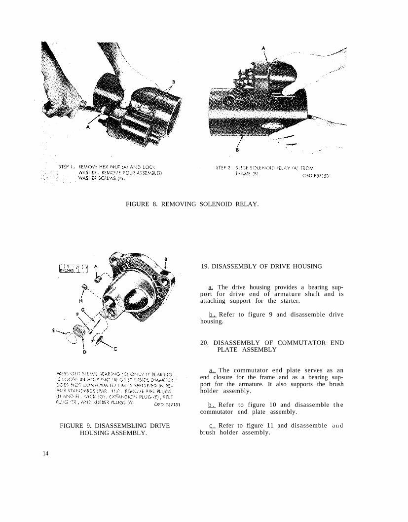
c. Refer to figure 6 and remove commutator ing and drive clutch assembly.end plate and brush holder assembly, and ar-mature.
e . Refer to figure 8 and remove solenoidd. Refer to figure 7 and remove lever hous- relay.
FIGURE 6. REMOVING COMMUTATOR END PLATE,BRUSHES, AND ARMATURE.
12

FIGURE 7. SEPARATING LEVER HOUSING AND ATTACHED PARTS FROM FRAME.
13
para. 41e
FIGURE 8. REMOVING SOLENOID RELAY.
FIGURE 9. DISASSEMBLING DRIVEHOUSING ASSEMBLY.
19. DISASSEMBLY OF DRIVE HOUSING
a. The drive housing provides a bearing sup-port for drive end of armature shaft and isattaching support for the starter.
b . Refer to figure 9 and disassemble drivehousing.
20. DISASSEMBLY OF COMMUTATOR ENDPLATE ASSEMBLY
a . The commutator end plate serves as anend closure for the frame and as a bearing sup-port for the armature. It also supports the brushholder assembly.
b . Refer to figure 10 and disassemble t h ecommutator end plate assembly.
c . Refer to figure 11 and disassemble a n dbrush holder assembly.
14

para. 41a
FIGURE 10. DISASSEMBLING COMMUTATOR END PLATE ASSEMBLY.
15

FIGURE 11. DISASSEMBLING BRUSH HOLDER ASSEMBLY.
16

FIGURE 12. REMOVING SOLENOID PLUNGER.
1 7

para. 41e
FIGURE 13. REMOVING SHIFT LEVER AND SHAFT.
21. DISASSEMBLY OF LEVER HOUSING ANDDRIVE CLUTCH ASSEMBLY
a. Disassembly of Lever Housing.
(1)
(2)
The lever housing serves as the arma-ture center bearing support, as an endplate for the motor portion of thestarter, and as a housing for the driveclutch and shift lever.
Refer to figures 12, 13, and 14 anddisassemble the lever housing.
b. Disassembly of Drive Clutch Assembly.
(1)
(2)
18
The drive clutch assembly transmitsthe torque developed by the armatureto the engine flywheel ring gear.
Disassemble the drive clutch assemblyas shown in figures 15 and 16. FIGURE 14. DISASSEMBLING LEVER HOUSING

FIGURE 15. DISASSEMBLING EXTERNAL PARTS OF DRIVE CLUTCH ASSEMBLY.
19

FIGURE 16. DISASSEMBLING INTERNAL PARTS OF DRIVE CLUTCH ASSEMBLY.
20

22. DISASSEMBLY OF SOLENOID RELAY gear and closes the electric circuit to the start-ing motor.
a. The solenoid relay shifts the starter drivepinion into mesh with the engine flywheel ring
b. Disassemble the solenoid relay as shownin figure 17.
FIGURE 17. DISASSEMBLING SOLENOID RELAY.
2 1

23. DISASSEMBLY OF FRAME ASSEMBLY in figures 18 and 19.
a . The frame assembly supports the fieldcoils, pole shoes, and field coil terminal stud. Note. Do not remove field coil unless inspec-
tion (par. 26i) indicates replacement is nec-b. Disassemble the frame assembly as shown essary.
FIGURE 18. REMOVING FIELD COILS.
22

FIGURE 19. FIELD COILS SEPARATED FROM FRAME.
Section III. CLEANING, INSPECTION, AND REPAIR
24. GENERAL
This section contains instructions for clean-ing, inspection, and repair or replacement ofthe parts of the starter. The following generalprocedures should be followed, where applicable.
a. Inspect all bolts, screws, nuts, and plugsfor worn or damaged threads. Discard and re-place all defective parts.
b . Discard and replace all preformed pack-ings, gaskets, and oil seals. Appendix II, RepairParts, lists a gasket and preformed packing setfor the starter.
25. CLEANING
a. General . Special cleaning instructions forelectrical parts are detailed below. Clean allother parts in dry cleaning solvent or mineralspirits paint thinner and dry with compresseda i r .
b . Field Coils. Clean field coils and framethoroughly with a cloth dampened with dry clean-ing solvent. Be careful not to damage protectiveinsulation coating. Dry thoroughly with com-pressed air.
c . Arma tu re . Remove loose particles fromarmature with compressed air and wipe with aclean cloth dampened with dry cleaning solvent.Clean commutator lightly with No. 00 sandpaperand remove all traces of dust with low-pressurecompressed air.
d . B r u s h H o l d e r Assembly. Clean brushholders, springs, and screws with a brush anddry cleaning solvent and dry them thoroughlywith compressed air. Clean insulation and plateswith a clean cloth dampened with dry cleaningsolvent and dry with compressed air.
e . Solenoid Relay. Clean parts with a cleancloth dampened with dry cleaning solvent and drywith low-pressure compressed air.
23

f . Brushes . Clean brushes with a clean, drycloth only. Do not permit dry cleaning solventto contact the brushes.
26. INSPECTION
a. Inspection of Drive Housing.
(1)
(2)
(3)
(4)
(5)
(6)
Inspect drive housing for cracks anddistortion. Replace housing if defective.
Inspect housing for scratches, burs, andnicks on machined surfaces. Repair asnecessary (par. 27a).—
Inspect threads in tapped holes in hous-ing for damaged threads. Replace hous-ing if threads are stripped or damagedbeyond repair.
Inspect sleeve bearing for discoloration,rough spots, score marks, scratches,and nicks.
Check inside diameter of sleeve bearing.Replace bearing if it does not conformto limits specified in wear limits (par.4 1 e ) . If sleeve bearing is removed,check bearing bore in housing. Replacehousing if bore does not conform tolimits specified in wear limit (par. 41e).
Note. Appendix II, Repair Parts, listsa sleeve bearing set to be used in re-pair of the starter.
Inspect wick for tears, fraying, or wear.Replace wick if defective.
b . Inspection of Commutator End Plate.
(1)
(2)
(3)
(4)
Inspect commutator end plate for cracksand distortion. Replace plate if defec-tive.
Inspect end plate for scratches, burs,and nicks on machined surfaces.
Inspect threads in tapped holes of endplate for damage. Replace end plate ifthreads are stripped or damaged beyondrepair .
Inspect sleeve bearing for discoloration,rough spots, score marks, scratches;and nicks.
(5)
(6)
Check diameter of sleeve bearing. Re-place bearing if it does not conform tolimits specified in wear limits (par.4 1 e ) . If sleeve bearing is removed,check bearing bore in end plate. Replaceend plate if bore does not comform tol imits specif ied in wear l imits (par .41e).—
Note. Appendix II, Repair Parts, listsa sleeve bearing set to be used in re-pair of the starter.
Inspect wick for tears, fraying, or wear.Replace wick if defective.
c. Inspection of Brush Holder Assembly andBrushes.
(1)
(2)
(3)
Check insulation, spacers, plates, andbrush holders for distortion and cracks.Replace defective parts.
Check brushes and springs for cracksor breaks. Check brush spring tension(step 1, fig. 10) for conformity to wearlimits (par. 4 1 a ) . If any brushes aredefective, replace entire set with brushkit. Replace springs if they do not con-form to wear limits.
Inspect terminal plate stud for damagedthreads.
d. Inspection of Armature.—
(1)
(2)
(3)
Check armature shaft and commutatorfor conformity to wear limits (par. 41e).Replace the armature if worn beyondlimits specified.
Inspect armature for grounds with a testlight by touching one of the test probesto the armature core and the other probeto one of the commutator bar risers(fig. 20). Test all commutator bars inthis manner. If the test light glows, thearmature is grounded and must be re-placed.
Inspect armature for short c i rcui tsusing a growler fixture. Place the ar-mature in the growler as shown in fig-ure 21. Hold a thin strip of steel, suchas a hacksaw blade about 1/32 inchaway from armature. While holding thesteel strip in position, rotate the arma-
24

FIGURE 20. TESTING ARMATURE FOR
(4)
(5)
GROUNDS.
ture slowly in the growler. A short cir-cuit will pull the steel strip tightlyagainst the armature core and cause thestrip to vibrate. If a short circuit isfound, the armature must be replaced.
Inspect armature shaft and commutatorfor runout using a lathe or "V" blocksand a dial indicator (fig. 22). If the run-out does not conform to wear limits(par. 41f), the commutator must be re-surfaced providing the diameter will notbe below the limits specified in wearlimits. If refinished diameter of com-mutator exceeds the limit, the armaturemust be replaced.
Inspect armature shaft splines for wearor damage. Replace the armature if thesplines are defective.
FIGURE 21. TESTING ARMATURE FORSHORT CIRCUITS USING A GROWLER.
color. If the contact surface is rough,pitted, scored, burned, or coated withhard carbon or oil, the commutator mustbe resurfaced. If mica is not 0.025 to0.032 inch below surface of commutator,it must be undercut to the correct depth.
(6) Inspect the commutator contact surface.A satisfactory condition is indicated byan even, highly burnished, dark-copper
FIGURE 22. CHECKINGCOMMUTATOR RUNOUT.
25

e . Inspection of Drive Clutch.
(1)
(2)
(3)
(4)
(5)
(6)
(7)
(8)
Inspect drive pinion for broken, chipped,or badly worn teeth. Replace pinion ifdefective.
Inspect internal splines in shell andpinion and external splines on sleeve forcracked, chipped, or broken condition.Replace defective parts.
Inspect all splines and pinion teeth fornicks and burs.
Inspect sleeve bearing for discoloration,rough spots, score marks, scratches,and nicks.
Check diameter of sleeve bearing. Re-place bearing if it does not conform tolimits specified in wear limits (par.4 1 e ) . If sleeve bearing is removed,check bearing bore in sleeve. Replacesleeve if bore does not conform to limitsspecified.
Check helical compression spring forconformance with wear l imits (par .41g). Replace spring if not within limitsspecified.
Inspect shell for cracked or broken con-dition. Inspect shell for rough spots,nicks, and scratches on internal pol-ished surface. Replace shell if defective.
Inspect sprags for nicks, scratches,chips, cracks, and broken condition.Inspect sprag (garter) spring for elon-gation and distortion. If any parts arede fec t ive , r ep l ace comple t e s e t o fsprags and spring.
f . Inspection of Lever Housing.
(1)
(2)
(3)
(4)
Inspect lever housing for cracks anddistortion. Replace housing if defective.
Inspect lever housing for scratches,burs, and nicks on machined surfaces.
Inspect threads in tapped holes in leverhousing. Replace housing if threads arestripped or damaged beyond repair.
Inspect sleeve bearing for discoloration,rough spots, score marks, scratches,and nicks.
(5)
(6)
(7)
Check inside diameter of sleeve bear-ing. Replace bearing if it does not con-form to limits specified in wear limits(par. 41e) . If sleeve bearing is re-moved, check bearing bore in housing.Replace housing if bore does not con-form to limits specified.
Check lever shaft bores and oil sealbore in housing. Replace housing ifbores do not conform to limits specifiedin wear limits (par. 41e) .
Inspect wick for tears, fraying, or wear.Replace wick if defective.
g . Inspection of Shift Lever, Shaft, SolenoidPlunger, Bellows, and Spring.
(1)
(2)
(3)
(4)
(5)
(6)
Inspect shift lever for cracks or dis-tortion. Check shaft bore in shift lever.Replace lever if defective or if boredoes not conform to limits specified inwear limits (par. 41c) .
Inspect shift lever clutch contact sur-faces for rough spots, scratches, andnicks.
Inspect solenoid plunger for cracks ordistortion. Inspect plunger rod threadsfor stripped or damaged condition. Re-place plunger if defective.
Inspect bellows for tears, punctures,and deterioration. Replace bellows ifdefective.
Inspect solenoid plunger compressionspring for cracks and distortion. Checkspring for conformance with wear limits(par. 41d) . Replace spring if defective.
Note. Appendix II, Repair Parts, listsa parts kit for repair of the startersolenoid.
Inspect lever shaft for rough spots,scratches, and nicks. Check diameterof shaft for conformance with wearlimits (par. 4 1 c ) . Replace shaft if de-f e c t i v e .
h . Inspection of Solenoid Relay.
(1) Inspect case and windings for crackedor broken condition. Check windings
26

(2)
for shorts or grounds with an ohmmeter.Replace solenoid relay if case and wind-ings are defective.
Inspect contact assembly for cracks,warpage, or broken springs. Replacecontact assembly if defective. Inspectcontacts on terminal studs for burningor pitting. Replace studs if contacts aredefective.
i. Inspection of Frame Assembly.
(1)
(2)
(3)
Inspect frame for cracks or distortion.Replace frame if defect ive. Inspecttapped holes in frame. Replace frameif threads are stripped or damaged be-yond repair.
Check field coils for insulation break-down with ohmmeter. Attach one probeof the ohmmeter to the frame and theother probe to one of the field coil ter-minals. The minimum reading shouldnot be less than one megohm. Replacedefective coils.
Inspect terminal screw for damagedthreads. Replace if threads are strippedor damaged beyond repair.
j. Thrust Washer and Spacer.
(1)
(2)
Inspect thrust washer and spacer forcracked or deformed condition. Replacedefective parts.
Check thickness of washer and spacer.Replace washer or spacer if it does notconform to limits specified in wearlimits (par. 41b) .
27. REPAIR
Note. The following subparagraphs cover onlythose parts wherein a repair operation will re-turn the damaged part to serviceable condition.Parts not detailed herein must be replaced whenthey fail to pass the required inspection (par. 26).
a . Repair of Drive Housing.
(1)
(2)
Smooth minor scratches, burs , anddents on machined surfaces of drivehousing using a fine mill file.
Repair damaged threads in drive hous-ing.
(3) Smooth minor rough spots, scratches,and nicks from inside bore of sleevebearing using a fine stone or crocuscloth dipped in dry cleaning solvent.
b . Repair of Commutator End Plate.
(1)
(2)
(3)
Smooth minor scratches, burs , anddents on machined surfaces of end plateusing a fine mill file.
Repair damaged threads of end plate.
Smooth minor rough spots, score marks,and scratches in inside bore of sleevebearing using a fine stone or crocuscloth dipped in dry cleaning solvent.
c . Repair of Brush Holder Assembly.
(1)
(2)
Inspect insulat ions, plates , spacers ,and brush holders for distortion andcracks. Replace defective parts.
Check brushes for cracks and excessivewear. Check springs for cracks anddistortion. Check brushes and springtension (step 1, fig. 10) for conformityto wear limits (par. 41a). If any brushesare defective, replace entire set withbrush kit. Replace springs if they donot conform to wear limits.
FIGURE 23. CUTTING TOOL SHARPENINGDIMENSIONS.
2 7

FIGURE 24. PROPER POSITION OFCUTTING TOOL.
d . Repair of Armature.
(1) Resurfacing. Sharpen lathe cutting toolto the dimensions given in figure 23.After grinding, hone the tool with a fine
FIGURE 25. UNDERCUTTING MICA USINGA POWER-DRIVEN TOOL.
hard stone to ensure a smooth cut duringthe turning operations. Position the toolwith respect to the commutator as shownin figure 24. Resurface the commutatorat 800 rpm taking only light cuts eachtime. No more than 0.005 inch shouldbe removed during any one cut and thefinal cut should not be more than 0.002inch. After resurfacing, check commu-
FIGURE 26. UNDERCUTTING MICA USING AN ALTERNATE HAND METHOD.
28

(2)
(3)
tator against limits specified in wearlimits (par. 41f) and undercut mica ((2)below) if refinished commutator is with-in limits specified. Replace armatureif commutator does not conform tomeasurements specified.
Undercutting mica. After resurfacingthe commutator, undercut mica to adepth of 0.025 to 0.032 inch below thesurface of the commutator using apower-driven undercutting tool (fig. 25).If a power-driven tool is not available,the mica may be undercut by hand asshown in figure 26.
Note. Use care in undercutting. Do notwiden commutator slots by removingmetal from segments, and do not leavethin edge of mica next to segments.Figure 26 illustrates examples of goodand bad undercutting.
Polishing commutator. After the micahas been undercut, remove all copperand mica particles with compressed air.Polish the commutator in a lathe withNo. 2/0 sandpaper (fig. 27) while thearmature is rotating at 1500 rpm. Afterpolishing the armature, check that thediameter is within the limits specifiedin wear limits (par. 41f).
e. Repair of Drive Clutch.
(1)
(2)
(3)
Smooth burs, nicks, and rough spots onsplines and pinion teeth using a finestone or crocus cloth dipped in drycleaning solvent.
Smooth rough spots, scoring, scratches,and nicks on inside bore of sleeve bear-ings and all surfaces of bronze bearingsusing crocus cloth dipped in dry clean-ing solvent.
Smooth minor rough spots, nicks, andscratches on internal polished surfaceof shell using a fine stone or crocuscloth dipped in dry cleaning solvent.If nicks and scratches cannot be re-moved or surface cannot be restoredto original finish, replace the shell.
f. Repair of Lever Housing.
(1)
(2)
(3)
Smooth minor scratches, burs, andnicks on machined surfaces of leverhousing using a fine mill file.
Repair damaged threads in housing.
Smooth minor rough spots, scoring,scratches, and nicks on inside bore ofsleeve bearing using a fine stone orcrocus cloth dipped in dry cleaning sol-vent.
FIGURE 27. POLISHING COMMUTATORWITH SANDPAPER.
g. Repair of Shift Lever, Shaft and SolenoidPlunger.
(1) Smooth minor rough spots, scratches,and nicks on clutch contact surfaces ofshift lever using a fine stone. Smoothminor rough spots, scratches, and nickson lever shaft
(2) Repair damaged
h. Repair of Frame.—
(1)
(2)
using a fine stone.
threads on plunger rod.
Smooth minor scratches, burs, and nickson machined surfaces of frame using afine mill file.
Repair damaged threads in frame. Re-pair damaged threads on field coil ter-minal stud.
29

Section IV. ASSEMBLY
28. GENERAL
a. The assembly procedures are covered inthe following paragraphs of this section. Ref-erence should be made during assembly andinstallation to the exploded views in the disas-sembly section for the proper relationship andposition of components.
b. Apply thread sealer to pole shoe screws,pipe plugs, and solenoid relay mounting screwsbefore assembly.
c. An oil hole must be drilled in the leverhousing, commutator end plate, and drive hous-ing sleeve bearing after installation. If anysleeve bearings are replaced, they must bereamed or burnished to the dimensions speci-fied in the "Sizes and fits of new parts" columnof the wear limits (par. 41e) after installationin housings, end plate, or clutch sleeve.
29. LUBRICATION
The lubricants listed in Table II should be
available for use during assembly. Table II liststhe lubricant, the part to which it is to be ap-lied, and the method of application. Make cer-tain that these instructions are performed dur-ing assembly.
30. ASSEMBLY OF FRAME ASSEMBLY
Note. The key letters shown below in paren-theses refer to figure 19 except where other-wise indicated.
a. Install terminal stud insulator bushing (D)on field coil terminal stud and position field coil(C) in frame (A). Install insulator (B) and twoinsulations (G) between frame and field coils.
b. Position each of four pole shoes (E), inturn, on coil inside frame align mating holes andsecure each pole shoe with two pole shoe screws(refer to step 2, fig. 18). Coat threads of poleshoe screws with a suitable thread sealer be-fore installation.
TABLE II. Lubrication Instructions
Par. ref. Point of lubrication Lubricant Instructions
32a Clutch and armature splines. GREASE, AIRCRAFT Coat splines.and and INSTRUMENT (GL).35c—
32b, Felt wicks and felt plugs. LUBRICATING OIL, Soak wick and33b, INTERNAL COMBUS- plugs untiland TION ENGINE (OE 10) saturated.34
32a Clutch sprags. LUBRICATING OIL, Lightly coat—INTERNAL COMBUS- sprags.TION ENGINE (OE 10)
35b Clutch shell (shift lever contact surface). GREASE, AIRCRAFT— Coat surface.and INSTRUMENT (GL).
32b, Preformed packings and gaskets. GREASE, GENERAL Lightly coat32c, PURPOSE, medium preformedand grade. packings and35c— gaskets.
3 0

c. Refer to figure 18, step 1 and install gas-ket (G), two nonmetallic washers (F), 0.520 ID,7/8 OD, 0.031 thick flat washer (E), 1/2-inchhex nut (D), field coil terminal-to-solenoid relayconnector (C), 1/2-inch lock washer (B), and1/2-inch hex nut (A).
d. Varnish inside of frame and coil assembly.Leave 0.38 inch from each end of frame free ofvarnish. Allow varnish to dry thoroughly beforeassembling starter.
31. ASSEMBLY OF SOLENOID RELAY
Note. The key letters shown below in paren-
theses refer to figure 17, step 3 except whereotherwise indicated.
a. Install terminal (G) on motor terminal stud(E) (short stud). Install motor terminal stud,battery terminal stud (F), terminal stud insula-tion strip (H), and terminal plate (J) with motorterminal stud in plate hole marked "MOTOR".Install one insulating bushing (K), one insulator(L), one 0.516 ID, 7/8 OD, 1/32 thick flat washer(M), two 1/2-inch lock washers (N), one 1/2-inch, 0.310 thick hex nut (P), and 1/2-inch,0.438 thick hex nut (Q) on each terminal stud.
b. Refer to figure 28 and complete assemblyof solenoid relay.
FIGURE 28. ASSEMBLING SOLENOID RELAY.
31

FIGURE 29. ASSEMBLING INTERNAL PARTS OF DRIVE CLUTCH ASSEMBLY.
32

32. ASSEMBLY OF DRIVE CLUTCH ANDLEVER HOUSING
a. Assembly of Drive Clutch. Refer to fig-ures 29 and 30 and assemble the drive clutch.After clutch has been assembled, it must bechecked for slippage.
(1) With clutch held stationary, the pinionmust slip when 4000 pound-inches is
(2)
applied in direction of torque. Torqueis counterclockwise as viewed frompinion end.
With clutch held stationary, twelvepounds pressure must be required tomove pinion to “stop” position, with a16 degree, 15 minute clockwise motionviewing pinion end.
FIGURE 30. ASSEMBLING EXTERNAL PARTS OF DRIVE CLUTCH ASSEMBLY.
33

FIGURE 31. INSTALLING SOLENOID PLUNGER AND LEVER.
34

c. Assembly of Solenoid Plunger and Lever.Refer to figure 31 and install solenoid plungerand lever in lever housing.
33. ASSEMBLY OF COMMUTATOR ENDPLATE ASSEMBLY
a. Assembly of Brush Holder Assembly.Refer to figure 11, step 3 and assemble thebrush holder assembly as follows:
(1)
(2)
(3)
(4)
b. Assembly of Lever Housing. Refer to fig-ure 14 and assemble the lever housing as fol-lows:
(1)
(2)
(3)
Install sleeve bearing (G) in lever hous-ing (F). Ream sleeve bearing bore tolimits specified in wear limits (par.41c).
Saturate wick (A) and felt plug (C) withoil (OE). Apply sealer to expansion plugseat. Install wick (A), felt plug (C), andexpansion plug (D). Fill reservoir withoil (OE) and install pipe plug (B).
Apply sealer to oil seal counterboreand install new oil seal (E).
(5)
Place insulated brush connection plate(J), brush insulation plate (H), and ter-minal plate (G) together. Install twononmetallic washers (K) in each of twoadjacent large holes in terminal plate(G).
Install brush holder plate insulation (L),insulated brush spacer plate (M), andbrush holder (E). Secure with a No. 10-32 by 21/32-inch fillister head screw (S)and No. 10 lock washer (R).
Install two helical torsion springs (Q)and a No. 10 lock washer (P) on insu-lated brush holder screw (2 inches lg)(T) and install screw.
Install remaining insulated brush holderfollowing same procedure.
Install grounded brush spacer plate (F)and brush holder (E) at top of terminalplate (G). Secure with No. 10-32 by 3/8-inch long fillister head screw (U) and aNo. 10 lock washer (B).
(6)
(7)
(8)
Install two brush springs (C) and a No.10 lock washer (D) on grounded brushholder screw (1-43/64-inch lg) (A) andinstall screw.
Install remaining grounded brush holderfollowing same procedure.
Check for grounded brush holder. Touchone probe of test lamp to terminal plate,and the other probe to the insulatedbrush holder. If the test lamp lights, aground is indicated. Disassemble andreplace defective parts if a ground isevident.
b. Assembly of Commutator End Plate. Referto figure 10 and assemble the commutator endplate as follows:
(1)
(2)
(3)
(4)
(5)
(6)
(7)
Install a new bearing (N, step 4) incommutator end plate (A). Ream sleevebearing bore to limits specified in wearlimits (par. 41e).
Saturate wick (R, step 4) and felt plug(T) with oil (OE).
Apply sealer to expansion plug seat.Install wick (R, step 4), felt plug (T),and expansion plug (S).
Fill reservoir with oil and install pipeplug (Q, step 4).
Install 0.516-inch ID nonmetallic washer(H, step 3) and preformed packing (G)on terminal stud of brush holder assem-bly (J) .
Install brush holder assembly (J) incommutator end plate (A) and securewith three No. 8 by 1/2-inch pan headscrews (M), lock washers (L), and flatwasher (K).
Install bushing (F, step 3), terminalstud insulator (E), 0.520-inch ID flatwasher (D), 1/2-inch lock washer (C),and 1/2- inch, 0.310-inch thick hex nut(B).
34. ASSEMBLY OF DRIVE HOUSING
Refer to figure 9 and assemble drive housingas follows:
35

a . Install new sleeve bearing (G) in drivehousing (B). Ream sleeve bearing bore to limitsspecified in wear limits (par. 41e) and drill oilhole.
b. Saturate wick (G), and felt plug (D) withoil (OE).
c. Apply sealer to expansion plug seat. In-stall wick (G), felt plug (D), and expansion plug(E).
d . Fill reservoir with oil and install pipeplugs (H and F).
e. Install rubber plugs (A) in housing (B).
35. ASSEMBLY OF STARTER ASSEMBLY
a. Installation of Solenoid Relay. Refer tofigure 32 and install solenoid relay on frameassembly.
b. Installation of Lever Housing and DriveClutch. Refer to figure 33 and install lever hous-ing drive clutch.
c . Installation of Commutator End PlateBrushes and Armature. Refer to figure 34 andinstall commutator end plate, brushes, and ar-mature.
If new brushes are to be installed, cuta strip of 2/0 sandpaper the width of thecommutator, and install on commutatorwith sand side out, see step 1.
Install commutator end plate on arma-ture. Lift brush springs using impro-vised brush spring lifter (fig. 3) andinstall brushes. Brushes must lie flatagainst sandpaper on commutator toobtain the desired brush seat contour.
Hold armature and carefully rotate com-mutator end plate assembly in a clock-wise direction three to five revolutionsto properly seat all brushes.
Lift brush springs and raise each brushand inspect seat contour to determinewhether or not the sanding operation issatisfactory. Refer to figure 35 for ex-amples of satisfactory brush seats.
FIGURE 32. INSTALLING SOLENOID RELAY.
36

FIGURE 33. INSTALLING LEVER HOUSING AND DRIVE CLUTCH ASSEMBLY.
3 7

FIGURE 34. INSTALLING COMMUTATOR END PLATE, BRUSHES, AND ARMATURE.
38

FIGURE 35. EXAMPLES OF SATISFACTORY AND UNSATISFACTORY BRUSH SEATS.
FIGURE 36. INSTALLING DRIVE HOUSING.
39

(5)
(6)
Mark location of brushes, and, removebrushes from holders. Remove commu-tator end plate from armature. Removesandpaper, and clean armature,brushes, and commutator end plate.Sanding dust can be removed using com-pressed air.
Install commutator end plate, brushes,armature, brush leads and terminallead following steps 2 through 6, fig-ure 34.
Note. The armature shaft and splinesmust be coated with grease (GL) beforeinstallation. Coat all exposed metal ofstarter lead and terminals with vinyllatex or equivalent.
d . Installation of Drive Housing. Refer tofigure 36 and install drive housing.
36. ADJUSTING DRIVE CLUTCH PINIONCLEARANCE
a. Check and adjust pinion clearance as de-scribed below. Refer to figure 37 for schematicwiring diagram of starter and solenoid con-nections.
(1)
(2)
Remove motor field coil connector fromthe motor switch terminal stud.
Remove ground lead assembly connect-ing motor solenoid terminal and starterground terminal stud.
FIGURE 37. STARTER WIRING DIAGRAM - SCHEMATIC.
40

(3)
(4)
(5)
(6)
(7)
Remove solenoid lead assembly con-necting battery switch terminal stud andbattery solenoid terminal.
Connect a 24-volt battery supply to bat-tery solenoid terminal and motor sole-noid terminal.
Momentarily hold a jumper lead fromthe motor switch terminal stud to themotor solenoid terminal. The pinionwill now shift into cranking position andremain so until the battery is discon-nected.
Push pinion back toward armature totake up slack movement.
Remove inspection plug and gasket (Band A, figure 7, step 1) and measurethe distance between pinion and drivehousing and adjust clearance to 23/64 ±1/32-inch by turning shaft nut (fig. 38).
FIGURE 38. ADJUSTING DRIVE CLUTCHPINION CLEARANCE.
b. Perform pinion block check as describedbelow.
(1) Connect a test light or other continuitychecker between the battery switch ter-minal stud and motor switch terminalstud.
(2)
(3)
Connect one of the posts of a 24-voltbattery to the battery solenoid terminal.Connect the other battery post to themotor solenoid terminal.
Place a 1-1/64-inch spacer block (fig.39) between the pinion and drive housingand momentarily hold a jumper leadfrom the motor switch terminal stud tothe motor solenoid terminal. The pinionwill now shift against the spacer andremain so until the jumper lead is dis-connected.
FIGURE 39. PINION BLOCK TEST.
(4)
(5)
(6)
An open circuit should be indicated be-tween the battery switch and motorswitch terminals. If continuity exists,decrease the pinion clearance (a above)to the minimum limit of 21/64-inch andthen recheck to make sure an open cir-cuit now exists.
Disconnect battery and test equipmentand install motor field connector, groundlead, and solenoid lead.
Install plug and gasket.
41

TM 9-2920-242-35
Section V. TESTING
37. GENERAL
Whenever a starter is tested check for anyunusual noises or vibration that might indicate anunserviceable condition. If either condition exists,further testing should not be attempted and thestarter must be disassembled and repaired.
38. NO-LOAD TEST AND LOCK TORQUE TEST
Caution: Never operate the starter motormo e thanr 30 seconds at a time. Allow the motorto cool for at least 2 minutes between eachcranking cycle. Overheating, caused by excessivecranking, will seriously damage the starter motor.
a.. No-Load. (fig. 40).
FIGURE 40. NO-LOAD TEST WIRINGDIAGRAM.
(1) Connect a 24-volt battery in series with anammeter and variable resistance to the
(2)
battery terminal of the solenoid.
For the return circuit, connect a lead fromthe frame of the starter to the battery.Connect a voltmeter from the solenoid“BAT” terminal to ground. Energize thesolenoid by connecting a jumper leadfrom the solenoid battery terminal to thesolenoid switch terminal. Check therotation speed of the armature with atachometer. Obtain the specified voltage(23.0 volts) by varying the resistance unit.MinimumCheck theMaximumamperes.
speed should be 7000 rpm.current draw on the ammeter.current draw should be 90
If a low speed, high current condition exists,check the armature for excessivearching, grounds, and shorts (par. 26d).Examine starter for armature drag. Ifdrag exists, check for loose pole shoescrews (fig. 18) and tighten as necessary.Check for armature eccentricity (par. 26d)or faulty bearings.
(3) If a low speed, low current conditionexists, inspect the starter for faultyconnections and for poor brush contact fig.35).
b. Lock–Torque Test. DELETED
42 Change 5

TM 9-2920-242-35
39. Waterproof Test
a. Connect an air line to the frame of the starter. Theconnection must be air tight.
b. Submerge the starter in the clean water up to thedrive housing and clutch assembly area. Do not allowwater to enter the drive housing and clutch area.Apply air pressure slowly. Watch for air bubbles.Increase pressure to 6 psi.
c. With air pressure remaining at 6 psi, allow starter toremain submerged for 30 minutes. No leaks shouldbe indicated during this period.
d. If leaks are indicated, disassemble starter, installnew preformed packings and gaskets. Coat packingsand gaskets with grease before installation and applysealer to all external screws and pipe plugs.Assemble starter and retest for water leaks.
Section VI. REPAIR STANDARDS
40. General corrosion will be approved for service. An asterisk (*)
The repair standards included herein give maximumin the wear limits column indicates that the part or
and minimum clearances of new or rebuilt parts. parts should be replaced when worn beyond the limits
They also give wear limits which indicate that point to given in the “Sizes and fits of new parts” column. In
which a part or parts may be worn before the “Sizes and fits of new parts” column, the letter “L”
replacement. Normally, all parts which have not been indicates a loose fit (clearance) and the letter “T”
worn beyond the dimensions shown in the “Direct and indicates a tight fit (interference). All dimensions aregeneral support wear limits” column or damaged from given in inches unless otherwise specified.
Change 5 4 3

C 3, TM 9-2920-242-35
41. Wear Limits
4 4

C 3, TM 9-2920-242-35
45

C 3, TM 9-2920-242-35
This page intentionally left blank
46

Paragraph Page
STARTER, ENGINE ELECTRICAL ASSEMBLY-(DELCO-REMY MODELS, 1113904 AND 1113944)
End Item Application
ENGINE, DIESEL, MULTIFUEL, TURBOCHARGED, 6-CYLINDER(MILITARY MODEL LDS-465-1A)
ENGINE, DIESEL, MULTIFUEL, 6-CYLINDER(MILITARY MODEL LD-465-1)
ENGINE ASSEMBLY W/ACCESSORIESMACK DIESEL MODEL ENDT-673
ENGINE DIESEL W/ACCESSORIESCUMMINS MODEL V8-300
C 1, TM 9-2920-242-35
Chapter 5. INTRODUCTIONSection I. General 4 2 , 4 3 5 1
I I . Descr ip t ion and data 4 4 , 4 5 5 1Chapter 6. PARTS, SPECIAL TOOLS, AND EQUIPMENT 5 3
7. TROUBLESHOOTING 5 58 . R E P A I R
Section I. Disassembly 4 6 - 5 1 5 7
I I . A s s e m b l y 5 2 - 5 7 6 2
III. Repair standards 5 8 , 5 9 6 5Appendix I. References - - - - - - - - - - - - - - - - - - - - - - - - - - - - - - - - - - - - - - ------- 6 7
II. REPAIR PARTS LIST
Sec t ion I . In t roduc t ion - - - - - - - - - - - - - - - - - - - - - - - - - - - - 1-8 6 9II. Direct support, general support, and depot maintenance repair parts list- - - - - - - - - - - -------- 7 2
47

PARA. 49
PAR. 50
PAR. 48c
PAR. 21a
PAR. 47
PAR. 21b. PAR. 27d
PAR. 50
PAR. 48b
C 1, TM 9-2920-242-35
VISUAL GUIDE TO CONTENTS
48

C 1, TM 9-2920-242-35
Figure 51. Starter assembly-typical assembled view.
4 9


C 1, TM 9-2920-242-35
CHAPTER 5INTRODUCTION
Section I. GENERAL
42. Scope
a. The procedures covered in this change willapply only to those models listed on the title page ofthis change (page 47). Because of earlier erroneousidentification, it is suggested the reader firmly fixin his mind the fact that the basic manual shouldhave been labeled Delco-Remy 1113904-B and not1113904 as indicated on basic manual.
b. The starters covered in this change are im-proved models incorporating new armatures andsolenoid relays. Although the starters differinternally from the earlier models, they are all to bereplaced by military model 10911018-1 (para 43,below).
43. Differences Between Models
a. Military part No. 10911018-1 was originallyassigned to Delco-Remy Model 1113904-B starter.Improvements were made to this model and it was
later designated as Delco-Remy model 1113943, andstill identified as military part No. 10911018-1.The nose housing on these two models are indexed to37 degrees 30 minutes for the Mack ENDT-673and LDS-465-1A engines, and 52 degrees 30 minutesfor the LDS-465-1 engine.
b. Military part No. 10911018 identifies Delco-Remy Model 1113904 starter. This starter issimilar to Delco-Remy model 1113943 except for thenose housing which is indexed 82 degrees, 30 minutesclockwise of the solenoid relay. This starter is usedon engine model LD-465-1.
c. Military part No. 10911018-1 also identifiesDelco-Remy model 1113944. This starter is similarto models 1113904 and 1113943 except that thepinion gear contains one blank tooth. This starteris used on engine model V8-300 only. The nosehousing is indexed at 47 degrees, 30 minutes clock-wise of the solenoid relay.
Section Il. DESCRIPTION AND DATA
44. Description 45. Data
Refer to paragraph 4 for description of starter, Refer to paragraph 5 for tabulated data on starter,part No. 10911018 and 10911018-1. part No. 10911018 and 10911018-1.
51


C 1, TM 9-2920-242-35
CHAPTER 6PARTS, SPECIAL TOOLS, AND EQUIPMENT
Refer to chapter 2 for parts, special tools, and equipment.
5 3


C 1 , T M 9 - 2 9 2 0 - 2 4 2 - 3 5
CHAPTER 7TROUBLESHOOTING
Refer to chapter 3 for troubleshooting procedures.
5 5


PAR. 41e
C 1, TM 9-2920-242-35
CHAPTER 8REPAIR
Section I. DISASSEMBLY
46. Disassembly into Subassemblies
Refer to paragraph 18 and disassemble starter intosubassemblies.
47. Disassembly of Drive Housing
Refer to figure 52 and disassemble drive housing.
48. Disassembly of Commutator End PlateAssembly
a. Refer to figure 53 and disassemble the com-mutator end plate assembly.
b. Refer to figure 11 and disassemble the brushholder assembly.
49. Disassembly of Lever Housing and DriveClutch Assembly
a. Disassembly of Lever Housing.
(1) Refer to figures 12 and 13 for removingsolenoid plunger, shift lever, and shaftfrom the lever housing.
(2) Refer to figure 54 for disassembly of leverhousing.
b. Disassembly ofassemble the drivefigures 15 and 16.
Drive Clutch Assembly. Dis-clutch assembly as shown in Figure 52. Disassembling drive housing assembly.
57

PAR. 41a
PAR. 41e
FIGURE 3
C 1, TM 9-2920-242-35
Figure 53. Disassembling commutator end plate assembly.
5 8

PARA. 41e
C 1, TM 9-2920-242-35
Figure 54. Disassembling lever housing.
59

C 1, TM 9-2920-242-35
50. Disassembly of Solenoid Relay
Refer to figure 55 and disassemble the solenoid relay.
Figure 55. Disassembling solenoid relay.
60

C 1, TM 9-2920-242-35
51. Disassembly of Frame Assembly
Refer to figures 56 and 57 and disassemble the frame assembly.
Figure 56. Removing field coils.
61

C 1, TM 9-2920-242-35
Figure 57. Field coils separated from frame.
Section II.
52. Assembly of Frame Assembly
Note. The key letters shown below in parentheses refer tofigure 57 except where otherwise indicated.
a. Install washer (B) and support, (A) on field coilterminal stud and position field coil (E) in frame (C).Install insulator (D) and two insulations (H)between frame and field coils.
b. Position each of four pole shoes (F), in turn, oncoil inside frame. Align mating holes and secureeach pole with two pole shoe screws (G) (2, fig. 56).Coat threads of pole shoe screws with a suitablethread sealer before installation.
Note. The key letters shown below in parentheses referto figure 56.
c. Install two nonmetallic washers (F), 0.520 ID.,7/8 OD., 0.031 thick flat washer (E), 1/2-inch hex nut(D), field coil terminal-to-solenoid relay connector(C), 1/2-inch lockwasher (B), and 1/2-inch hex nut (A).
ASSEMBLY
d. Varnish inside of frame and coil assembly.Leave 0.38 inch from each end of frame free ofvarnish. Allow varnish to dry thoroughly beforeassembling starter.
53. Assembly of Solenoid RelayNote. The key letters shown below in parentheses refer to
figure 55, step 3, except where otherwise indicated.a. Install terminal (G) on motor terminal stud (E)
(short stud). Install motor terminal stud, batteryterminal stud (F), terminal stud insulation strip (H),and terminal plate (J) with motor terminal stud inplate marked MOTOR. Install one insulatingbushing (K), one insulator (L), one 0.516 ID.,7/8 OD., 1/32 thick flat washer (M), ½-inch lockwasher(N), ½-inch, 0.312 thick hex nut (P), ½-inchlockwasher (N) and ½-inch, 0.438 thick hex nut (Q)on each terminal stud.
b. Refer to figure 58 and complete assembly ofsolenoid relay.
62

C 1, TM 9-2920-242-35
Figure 58. Assembling solenoid relay.
54. Assembly of Drive Clutch and LeverHousing
a. Assembly of Drive Clutch. Refer to paragraph32a and figures 29 and 30.
b. Assembly of Lever Housing. Refer to figure 54.(1) Install sleeve bearing (H) in lever housing
(G). Ream sleeve bearing bore to limitsspecified in wear limits (para 41c). Installbrake washer (J).
(2) Saturate wick (A) and felt plug (C) withoil (OE). Apply sealer to expansion plugseat. Install felt plug (C), gasket (D), andexpansion plug (E). Install wick (A) andfill reservoir with oil (OE) and install pipeplug (B).
(3) Apply sealer to oil seal counterbore andinstall new oil seal (F).
c. Assembly of Solenoid Plunger and Lever. Referto figure 31 and install solenoid plunger and lever inlever housing.
55. Assembly of Commutator End PlateAssembly
a. Assembly of Brush Holder Assembly. Refer toparagraph 33a and figure 11 and assemble the brushholder assembly.
b. Assembly of Commutator End Plate. Refer tofigure 53 and assemble the commutator end plate asfollows:
(1)
(2)
(3)
(4)
Install a new bearing (N, step 4) in com-mutator end plate (A). Drill oilhole andream sleeve bearing bore to limits specifiedin wear limits (para 41e).
Saturate wick (R, step 4) and felt plug (U)with oil (OE).
Apply sealer to expansion plug seat. Installfelt plug (U, step 4), gasket (T), and ex-pansion plug (S).
Install wick (R, step 4) and fill reservoirwith oil, and install pipe plug (Q).
6 3

C 1, TM 9-2920-242-35
(5)
(6)
(7)
Install 0.516-inch ID nonmetallic washer(H, step 3) and rubber bushing (G) onterminal stud of brush holder assembly (J).
Install brush holder assembly (J) in com-mutator end plate (A), and secure withthree No. 8 by ½-inch pan head screws(M), lockwashers (L), and flat washers (K).
Install bushing (F, step 3), terminal studinsulator (E), 0.520-inch ID flat washer(D), ½-inch lockwasher (C), and ½-inch,0.310-inch thick hex nut (B).
56. Assembly of Drive Housing
Refer to figure 52 and assemble drive housing asfollows:
Figure 59. Drive housing position–model ENDT-673 engineapplication.
a. Install new sleeve bearing (C) in drive housing(B). Drill oilhole and ream sleeve bearing bore tolimits specified in wear limits (para 41e).
b. Saturate wick (H), and felt plug (D) with oil(OE).
c. Apply sealer to expansion plug seat. Installfelt plug (D), gasket (F), and expansion plug (E).
d. Install wick (H) and fill reservoir with oil (OE),and install pipe plug (G).
e. Install rubber plugs (A) in housing (B).
57. Assembly of Starter Assembly
Refer to paragraph 35 for assembly for starterassembly except refer to figures 59 through 62 whenindexing the drive housing.
Figure 60. Pinion housing position—model LD-465-1 engineapplication.
64

C 1, TM 9-2920-242-35
Figure 61. Drive housing position—model LDS-465-1 and Figure 62. Drive housing position—model V8-300 engineLDS-465-1A engine application. application.
Section III. REPAIR STANDARDS
58. General 59. Wear Limits
Refer to paragraph 40. Refer to paragraph 41.
65


C 1, TM 9-2920-242-35
APPENDIX IREFERENCES
1. Publication Indexes
The following indexes should be consulted frequently for latest changes or revisions of references given inthis appendix and for new publications relating to material covered in this manual.
Index of Army Motion Pictures, Film Strips, Slides, Tapes, and Phono-Recordings . . . . . . DA Pam 108-1Military Publications:
Index of Administrative Publications . . . . . . . . . . . . . . . . . . . . . . . . . . . . . . . . . . . . . . . . . . . . . . DA Pam 310-1Index of Blank Forms . . . . . . . . . . . . . . . . . . . . . . . . . . . . . . . . . . . . . . . . . . . . . . . . . . . . . . . . . . . . . . . . DA Pam310-2Index of Doctrinal, Training, and Organizational Publications. . . . . . . . . . . . . . . . . . . . DA Pam 310-3Index of Technical Manuals, Technical Bulletins, Supply Manuals (Types 7, 8, and 9), DA Pam 310-4
Supply Bulletins, Lubrication Orders, and Modification Work Orders.Index of Graphic Aids and Devices . . . . . . . . . . . . . . . . . . .. . . . . . . . . . . . . . . . . . . . . . . . . . . . . . . . . . DA Pam 310-5Index of Supply Catalogs and Supply Manuals (Excluding Types 7, 8, and 9) . . . . . . DA Pam 310-6
2. Publication Reference
The following publication is referenced within this manual:
TM 38-750 . . . . . . . . . . . . . . . . . . . . . . . . . . . . . . . . . . . . . . . . . . . . . . . . . . . Army Equipment Record Procedures
67


C 3, TM 9-2920-242-35
APPENDIX IIDIRECT AND GENERAL SUPPORT
MAINTENANCE REPAIR PARTS
Section I. INTRODUCTION
1. ScopeThis appendix lists repair parts required for theperformance of direct and general support of theDelco-Remy Engine Electrical Starter Assemblies,Models 1113943, 1113904, and 1113944.
2. GeneralThis Repair Parts List is divided into the follow-ing sections:
a. Repair Parts - Section II. A list of repairparts authorized for the performance of mainte-nance at the direct and general support level infigure and item number sequence.
b. Special Tools, Test and Support Equipment.Not applicable.
c. Federal Stock Number and Reference NumberIndex - Section III. A list of Federal stock num-bers in ascending numerical sequence followed bya list of reference numbers in ascending alpha-numeric sequence, cross-referenced to the illus-tration figure number and item number.
3. Explanation of ColumnsThe following provides an explanation of columnsin the tabular lists in Sections II and III.
a. Source, Maintenance, and RecoverabilityCodes (SMR), Column 1:
(1) Source code, indicates the selection statusand source for the listed item. Source codes used
Code
P10
M
A
X
X1
X2
G
Explanationare not subject to the provisions of AR 380-41.Assigned to items which are NSA design controlled:special tools, test, measuring and diagnostic equip-ment for COMSEC support, which are accountableunder the provisions of AR 380-41, and which arestocked and supplied by the Army COMSEC LogisticSystem.Repair Parts, Special Tools and Test Equipment whichare not procured or stocked, as such, in the supplysystem but are to be manufactured at indicatedmaintenance levels.Assemblies which are not procured or stocked as such,but are made up of two or more units. Such com-ponent units carry individual stock numbers and de-scriptions, are procured and stocked separately andcan be assembled to form the required assembly atindicated maintenance categories.Parts and assemblies that are not procured or stockedbecause the failure rate is normally below that of theapplicable end item of component. The failure of suchpart or assembly should result in retirement of theend item from the supply system.Repair Parts which are not procured or stocked. Therequirement for such items will be filled by the nexthigher assembly or component.Repair Parts, Special Tools, and Test Equipment whichare not stocked and have no foreseen mortality. Theindicated maintenance category requiring such repairparts will attempt to obtain the parts through canni-balization or salvage, if not obtainable through can-nibalization or salvage the item may be requisitionedwith exception data, from the end item manager, forimmediate use.Major assemblies that are procured with PEMA funds
areCodeP
P2
P9
—
Explanation
Repair Parts, Special Tools and Test Equipment suppliedfrom the GSA/DSA, or Army supply system, andauthorized for use at indicated maintenance categories.Repair Parts, Special Tools and Test Equipment whichare procured and stocked for insurance purposesbecause the combat or military essentiality of the enditem dictates that a minimum quantity be availablein the supply system.Assigned to items which are NSA design controlled:unique repair parts, special tools, test, measuring anddiagnostic equipment, which are stocked and sup-plied by the Army COMSEC Logistic System and which
for initial issue only as exchange assemblies at DSUand GSU level. These assemblies will not be stockedabove the DS and GS level or returned to depot supplylevel.
NOTECannibalization or salvage may be usedas a source of supply for any items sourcecoded above, except those coded X1.(2) Maintenance Code, indicates the lowest
category of maintenance authorized to install thelisted item. The maintenance level codes are- Code Explanation
C Crew or Operator Maintenance
6 9

C 4, TM 9-2920-242-35Code Explanation
O Organization Maintenance.F Direct Support Maintenance.H General Support Maintenance.D Depot Maintenance.
(3) Recoverability Code, indicates whetherunserviceable items should be returned for re-covery or salvage. Recoverability Codes are –
Code
R
S
T
U
Explanation
Applied to repair parts, (assemblies and components),special tools, and test equipment which are consideredeconomically reparable at direct and general supportmaintenance levels. When the item is no longer eco-nomically reparable, it is normally disposed of at theGS level. When supply considerations dictate, some ofthese repair parts may be listed for automatic returnto supply for depot level repair as set forth in AR 710-50. When so listed, they will be replaced by supply onan exchange basis.Repair Parts, Special Tools, Test Equipment and assem-blies which are economically reparable at DSU andGSU activities and which normally are furnished bysupply on an exchange basis. When items are deter-mined by a GSU to be uneconomically reparable, theywill be evacuated to a depot for evaluation andanalysis before final disposition.Higher dollar value recoverable repair parts, specialtools and test equipment which are subject to specialhandling and are issued on an exchange basis. Suchitems will be evacuated to the depot for overhaul or finaldisposition, Communications - Electronics and MissileSupport Items will be repaired/overhauled only at depots.Repair Parts, Special Tools and Test Equipment specifi-cally selected for salvage by reclamation units be-cause of precious metal content, critical materials,high dollar value or reusable casings or castings.
NOTEWhen no code is indicated in the recover-ability column, the part will be considerednon-recoverable.
b. Federal Stock Number, Column 2. This col-umn indicates the Federal stock number assignedto the item and will be used for requisitioningpurposes.
c. Description, Column 3. This column indi-cates the Federal item name and any additionaldescription of the item required. A part numberor other reference number is followed by theapplicable five-digit Federal supply code formanufacturers in parentheses. Repair partsquantities included in the kits, sets, and assem-blies are shown in front of the repair part name.
d. Unit of Measure (U/M), Column 4. A twocharacter alphabetic abbreviation indicating the
amount or quantity of the item upon which theallowances are based, e.g., ft, ea, pr, etc.
e. Quantity Incorporated in Unit, Column 5.This column indicates the quantity of the itemused in the functional group. A “V” appearingin this column in lieu of a quantity indicates thata definite quantity cannot be indicated (e.g.,shims, spacers, etc.).
f. 30-Day DS/GS Maintenance Authorization,Columns 6, and 7
(1) The Repair Parts List includes asteriskentries in separate columns - one for DirectSupport (DS) and one for General Support (GS)- as appropriate to indicate the total range ofrepair parts authorized for use at that categoryor required to be removed or disassembled dur-ing the performance of authorized maintenanceoperations. They will be requisitioned initiallyon an “as required” basis. The repair partsauthorized at the DS/GS levels will be thoseauthorized for the maintenance mission at theselevels. Requirements for repair part stockage andfor distribution to supported units will be basedon demand and determined in accordance withAR 711-16.
(2) Special Tools or Test, Measurement andDiagnostic Equipment (TMDE) and other supportequipment peculiar to an item are listed withquantities in the appropriate density spread/al-lowance columns. (Not applicable).
g. 1-Year Allowances Per 100 Equipments/Contingency Planning Purposes, Column 8. Thiscolumn indicates the total requirement for con-tingency planning purposes. An asterisk indicatesauthorization to obtain or use as required.
h. Depot Maintenance Allowance Per 100 Equip-ments, Column 9. This column indicates authoriza-tion for depot use.
i. Illustration, Column 10. This column is divid-ed as follows:
(1) Figure number, Column 10a. Indicates thefigure number of the illustration in whichitem is shown.
(2) Item number, Column 10b. Indicatescallout number used to reference the item inillustration.
the
thethe
7 0
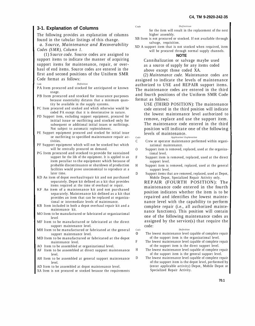
C4, TM 9-2920-242-35
3-1. Explanation of ColumnsThe following provides an explanation of columnsfound in the tabular listings of this change.
a. Source, Maintenance and RecoverabilityCodes (SMR), Column 1.
(1) Source code. Source codes are assigned tosupport items to indicate the manner of acquiringsupport items for maintenance, repair, or over-haul of end items. Source codes are entered in thefirst and second positions of the Uniform SMRCode format as follows:Code Definition
PA Item procured and stocked for anticipated or knownusage.
PB Item procured and stocked for insurance purposesbecause essentiality dictates that a minimum quan-tity be available in the supply systems.
PC Item procured and stocked and which otherwise would becoded PA except that it is deteriorative in nature.
PD Support item, excluding support equipment, procured forinitial issue or outfitting and stocked only forsubsequent or additional initial issues or outfittings.Not subject to automatic replenishment.
PE Support equipment procured and stocked for initial issueor outfitting to specified maintenance repair ac-tivities.
PF Support equipment which will not be stocked but whichwill be centrally procured on demand.
PG Item procured and stocked to provide for sustainedsupport for the life of the equipment. It is applied to anitem peculiar to the equipment which because ofprobable discontinuance or shutdown of productionfacilities would prove uneconomical to reproduce at alater time.
KD An item of depot overhaul/repair kit and not purchasedseparately. Depot kit defined as a kit that providesitems required at the time of overhaul or repair.
KF An item of a maintenance kit and not purchasedseparately. Maintenance kit defined as a kit thatprovides an item that can be replaced at organiza-tional or intermediate levels of maintenance.
KB Item included in both a depot overhaul repair kit and amaintenance kit.
MO Item to be manufactured or fabricated at organizationallevel
MF Item to be manufactured or fabricated at the directsupport maintenance level.
MH Item to be manufactured or fabricated at the generalsupport maintenance level.
MD Item to be manufactured or fabricated at the depotmaintenance level.
AO Item to be assembled at organizational level.AF Item to be assembled at direct support maintenance
level.AH Item to be assembled at general support maintenance
level.AD Item to be assembled at depot maintenance level.XA Item is not procured or stocked because the requirements
Code Def in i t ion
for the item will result in the replacement of the nexthigher assembly.
XB Item is not procured or stocked. If not available throughsalvage, requisition.
XD A support item that is not stocked when required, itemwill be procured through normal supply channels.
NOTECannibalization or salvage maybe usedas a source of supply for any items codedabove except those coded XA.(2) Maintenance code. Maintenance codes are
assigned to indicate the levels of maintenanceauthorized to USE and REPAIR support items.The maintenance codes are entered in the thirdand fourth positions of the Uniform SMR Codeformat as follows:
Code
C
O
F
H
D
Code
oF
H
D
USE (THIRD POSITION): The maintenancecode entered in the third position will indicatethe lowest maintenance level authorized toremove, replace and use the support item.The maintenance code entered in the thirdposition will indicate one of the followinglevels of maintenance.
Application/Explanation
Crew or operator maintenance performed within organi-zational maintenance.
Support item is removed, replaced, used at the organiza-tional level.
Support item is removed, replaced, used at the directsupport level.
Support item is removed, replaced, used at the generalsupport level.
Support items that are removed, replaced, used at Depot,Mobile Depot, Specialized Repair Activity only.
REPAIR (FOURTH POSITION): Themaintenance code entered in the fourthposition indicates whether the item is to berepaired and identifies the lowest mainte-nance level with the capability to performcomplete repair (i.e., all authorized mainte-nance functions). This position will containone of the following maintenance codes asassigned by the service(s) that require thecode:
Definition
The lowest maintenance level capable of complete repairof the support item is the organizational level.
The lowest maintenance level capable of complete repairof the support item is the direct support level.
The lowest maintenance level capable of complete repairof the support item is the general support level.
The lowest maintenance level capable of complete repairof the support item is the depot level, performed by(enter applicable activity) Depot, Mobile Depot orSpecialized Repair Activity.
70.1

C4, TM 9-2920-242-35
Code Application/Explanation
L Repair restricted to designed Specialized Repair Activity.Z Non-repairable. No repair is authorized.B No repair is authorized. The item maybe reconditioned
by adjusting, lubrication, etc., at the user level. Noparts or special tools are procured for the mainte-nance of this item.
(3) Recoverability code. Recoverability codesare assigned to support items to indicate thedisposition action on unserviceable items. Therecoverability code is entered in the fifth positionof the Uniform SMR Code format as follows:
Def in i t i on
Nonrepairable item. When unserviceable, condemn anddispose at the level indicated in position 3.
Reparable item. When uneconomically repairable,condemn and dispose at organizational level.
Reparable item. When uneconomically repairable, con-demn and dispose at the direct support level.
Reparable item. When uneconomically repairable, con-demn and dispose at the general support level.
Reparable item. When beyond lower level repair capabili-ty, return to depot. Condemnation and disposal notauthorized below depot level.
Reparable item. Repair, condemnation and disposal notauthorized below depot/Specialized Repair Activitylevel.
Item requires special handling or condemnation proce-dures because of specific reasons (i.e., precious metalcontent, high dollar value, critical material or hazard-ous material). Refer to appropriate manuals/directives for specific instructions.
4. Special Informationa. Identification of the usable on codes included
in column 3 of this publication are:Code Used on
A Starter, Engine Electrical, Delco-Remy Model 1113943B Starter, Engine Electrical, Delco-Remy Model 1113904C Starter, Engine Electrical, Delco-Remy Model 1113944
b. Applicable publications are:TM 9-2320-206 . . .Truck, Cargo, 10 Ton 6x6
(M125)TM 9-2320-211 . . .Truck, Cargo, 5 Ton 6x6
(M41, M54, M55)TM 9-2320-230 . . .Truck, Cargo, 5 Ton 8x8
(M656)TM 9-2815-210 . . .DS/GS and depot mainte-
nance manual: Engine(multifuel), (LDS 465-1and LDS 465-1A)
TM 9-2815-207 . . .DS/GS maintenance manualfor Engine, diesel: (MackModel ENDT 673)
TM 9-2815-213 . . .DS/GS maintenance manualfor Engine, diesel: (Cum-mins Model V8-300)
c. Repair parts mortality has been based on 8hours of operation per day.
d. Action Change Codes. Action change codeslisted in the left hand margin of the listing pagesdenotes the followingCode Definition
C(Change) . . . . . . . . . . . . . .Indicates a change in data otherthan the FSN since the previouspublication.
D (Deletion) . . . . . . . . . . . . Indicates that an FSN has beendeleted and not replaced.
N (New) . . . . . . . . . . . . . . . .Indicates an FSN not previouslyincluded in the basic publicationor changes.
R (Replacement) . . . . . . . . Indicates that an FSN has beendeleted and replaced or changed
5. How to Locate Repair Partsa. When national stock number or reference
number is unknown:(1) First. Using the table of contents, deter-
mine the functional group, i.e., engine, engineassembly, transmission, transmission assembly,within which the repair part belongs. This isnecessary since illustrations are prepared forfunctional groups, and listings are divided into thesame groups.
(2) Second. Find the illustration covering thefunctional group, to which the repair part belongs.
(3) Third. Identify the repair part on theillustration and note the illustration figure anditem number of the repair part.
(4) Fourth. Using the Repair Parts Listing,find the functional group to which the repair partbelongs and locate the illustration figure and itemnumber notes on the illustration.
b. When national stock number or referencenumber is known:
(1) First. Using the Index of National StockNumbers and Reference Numbers find the perti-nent National stock number or reference number.This index is in ascending NSN sequence followedby a list of reference numbers in ascendingalphanumeric sequence, cross-reference to theillustration figure number and item number.
(2) Second. Using the Repair Part Listing, findthe functional group of the repair part and theillustration figure number and item number
70.2

referenced in the Index of National Stock Num-bers and Reference Numbers.
6. Reporting of Equipment Manual Im-provementsYou can improve this manual by recommending
C4, TM 9-2920-242-35
improvements using DA Form 2028 (Recom-mended Changes to Publications and BlankForms) and mail the form direct to Commander,US Army Tank-Automotive Command, ATTN:AMSTA-MSP, Warren, MI 48090. A reply will befurnished direct to you.
70.3

in column 3 of this publication are —
Code Used on
A Starter, Engine Electrical, Delco-Remy Model 1113943B Starter, Engine Electrical, Delco-Remy Model 1113904C Starter, Engine Electrical, Delco-Remy Model 1113944
b. Applicable publications are:TM 9-2320-206 Truck, Cargo, 10 ton 6 x 6 (M125)TM 9-2320-211 Truck, Cargo, 5 ton 6 x 6 (M41, M54,
M55)TM 9-2320-230 Truck, Cargo, 5 ton 8 x 8 (M656)TM 9-2815-210 DS/GS and depot maintenance
manual: Engine (multifuel), (LDS465-1 and LDS 465-1A)
TM 9-2815-207 DS/GS maintenance manual forEngine, diesel: (Mack ModelENDT 673)
TM 9-2815-213 DS/GS maintenance manual forEngine, diesel: (Cummins ModelV8-300)
c. Repair parts mortality has been based on 8hours of operation per day.
5. How to Locate Repair Partsa. When Federal stock number or reference
number is unknown:(1) First. Using the table of contents, deter-
mine the functional group, i.e., engine, engineassembly, transmission, transmission assembly,within which the repair part belongs. This isnecessary since illustrations are prepared forfunctional groups, and listings are divided intothe same groups.
(2) Second. Find the illustration covering thefunctional group, to which the repair part belongs.
(3) Third. Identify the repair part on the illus-tration and note the illustration figure and itemnumber of the repair part.
(4) Fourth. Using the Repair Parts Listing,find the functional group to which the repair partbelongs and locate the illustration figure and itemnumber notes on the illustration.
b. When Federal stock number or referencenumber is known:
(1) First. Using the Index of Federal Stock
C 3, TM 9-2920-242-35
Numbers and Reference Numbers find the perti-nent Federal stock number or reference number.This index is in ascending FSN sequence followedby a list of reference numbers in ascending alpha-numeric sequence, cross-reference to the illustra-tion figure number and item number.
(2) Second. Using the Repair Part Listing,find the functional group of the repair part andthe illustration figure number and item numberreferenced in the Index of Federal Stock Num-bers and Reference Numbers.
6. Federal Supply Codes forManufacturers
Code Manufacturer
16764 Delco-Remy Division of General MotorsCorporation2401 Columbus AvenueAnderson, IN 46011
19207 Army Tank-Automotive CommandWarren, MI 48090
21450 Ordnance Corps Engineering Standards,Rock Island ArsenalRock Island, IL
24617 General Motors Corporation3044 Grand Blvd. W.Detroit, MI 48202
72850 Bendix Corporation18 St. and Oakwood Ave.Elmira, NY 14903
88044 Aeronautical Standards GroupDepartment of Navy and Air Force
96906 Military Standards Promulgated byStandardization Division Directorateof Logistic Services DSA
7. Reporting of EquipmentManual Improvements
The reporting of errors, omissions, and recom-mendations for improving this publication by theindividual user is encouraged. Reports should besubmitted on DA Form 2028 (RecommendedChanges to Publications) and forwarded directlyto Commanding General, U.S. Army Tank-Auto-motive Command, ATTN: AMSTA-MAP, Warren,MI 48090.
71

Section II.
GR
OU
P 06
C4 TM
9-2920-242-34
72
LOGSA
2920-0226-6545
LOGSA
2920-911-5637
LOGSA
2920-912-9510
LOGSA
2920-877-2227
LOGSA
6110-757-7187
LOGSA
2920-807-2408
LOGSA
2920-086-7979
LOGSA
2920-865-8270
LOGSA
5305-068-0515
LOGSA
5310-582-5965
LOGSA
5977-786-9564

C4 T
M 9-2920-242-34
73
LOGSA
5977-754-8153
LOGSA
5305-984-6191
LOGSA
LOGSA
5310-045-3299
LOGSA
5305-984-6193
LOGSA
5310-178-9612
LOGSA
2920-015-3058
LOGSA
9320-757-7131
LOGSA
2920-973-1559
LOGSA
2920-089-3367
LOGSA
5365-715-1152
LOGSA
2920-839-1864
LOGSA
2920-089-3368
LOGSA
3120-661-8951
LOGSA
3120-350-4492
LOGSA
2920-089-3369
LOGSA
5330-584-0265
LOGSA
5330-842-1901
LOGSA
5330-291-2786
LOGSA
5330-579-7544
LOGSA
5970-734-8918
LOGSA
5970-734-8919

C4
TM
2920-242-34
74
LOGSA
2920-999-2399
LOGSA
5330-584-0266
LOGSA
2920-089-3370
LOGSA
5310-297-7319
LOGSA
5365-715-1152
LOGSA
2920-999-2527
LOGSA
5330-719-5470
LOGSA
5310-262-4753
LOGSA
5306-783-5188
LOGSA
5306-783-5183
LOGSA
2920-060-7252
LOGSA
5330-842-1901

Figure 63.
FIG
UR
E 63
C 3, TM
9-2920-242-3575

C4, TM 9-2920-242—35
Section III. INDEX – NATIONAL STOCK NUMBER AND REFERENC NUMBER
CROSS-REFERENCE TO FIGURE AND ITEM NUMBER INDEX National
Stock Number
Figure No. Item No. National
Stock Number
Figure No.
Item No. 2920-00-015-3058 2920-00-060-7252 2920-00-086-7979 2929-00-089-3367 2920-00-089-3368 2920-00-089-3369 2920-00-089-3370 2920-00-226-6545
2920-00-807-2408 2920-00-839-1864 2920-00-865-8270 2920-00-877-2227 2920-00-911-5637
2920-00-912-9510
2920-00-973-1559 2920-00-999-2399 2920-00-999-2527 3120-00-350-4492 3120-00-661-8951 5305-00-068-0515 5305-00-984-6191
63 Kit 63 Kit Kit Kit Kit 63 63 63 63 63 63 63 63 63 63 63 63 63 63
36 N.1 19 N.1 N.1 N.1 N.1 Starter Assy 14 10(Kit) 20 1 Starter Assy Starter Assy 40 27(Kit) 13(KIT) 21(Kit) 7(Kit) 25 31
5305-00-984-6193 5306-00-783-5183 5306-00-783-5188
5310-00-045-3299 5310-00-178-9612 5310-00-262-4753 5310-00-297-7319 5310-00-582-5965 5330-00-291-2786 5330-00-579-7544 5330-00-584-0265 5330-00-584-0266 5330-00-719-5470 5330-00-842-1901 5340-00-232-5723 5360-00-812-0196 5365-00-715-1152 5970-00-734-9818 5970-00-734-8919 5977-00-754-8153 5977-00-786-9564 6110-00-757-7187 9320-00-757-7131
63 63 63
63 63 63 63 63 63 63 63 63 63 63 63 63 63 63 63 63 63 63 63
34 39(Kit) 38(Kit) 33 35 32(Kit) 5 26 11(Kit) 12(Kit) 42(Kit) 43(Kit) 16(Kit) 3(Kit) 22(Kit) 9(Kit) 8(Kit) 23(Kit) 24(Kit) 30 29 6A 37
Reference No. Mfg. Code
Fig. No.
Item No.
Reference No.
Mfg. Code
Fig. No.
Item No.
MS16624-1037 MS28775-010 MS28775-012 MS28775-243 MS35206-243 MS35206-245 MS35388-42 MS35338-44 MS35648-6 MS90727-8 10911018 10911018-1 10951331 10951342 1113944 11602684 11610014 1911644 1916439
96906 96906 96906 96906 96906 96906 96906 96906 96906 96906 19207
19207
19207 19207 16764
19207 19207 16764 16764
63 63 63 63 63 63 63 63 63 63 63
63
63 63 63
63 N.1 63 63
8(Kit) 43(Kit) 42(Kit) 12(Kit) 31 34 33 26 22(Kit) 25 Starter Assy Starter Assy 41(Kit) 2(Kit) Starter Assy 4(Kit) (Kit) 5(Kit) 20
1922457 1936466 1942969 1945484 1948515 1949606 1949619 1951069 1951073 1965419 1965421 482204 500013 5702705 5702706 5702707 5702708 5702709 5702745 7348918 7348919 7348958 7529187
16764 16764 16764 16764 16764 16764 16764 16764 16764 16764 24617 72850 21450 19207 19207 19207 19207 19207 19207 19207 19207 19207 19207
63 63 63 63 63 63 63 63 63 63 63 N.1 63 63 Kit Kit Kit Kit Kit 63 63 63 63
16(Kit) 13(Kit) 27(Kit) 6A 29 1 37 6 19 17(Kit) 18(Kit) (Kit) 11(Kit) 30 N.1 N.1 N.1 N.1 N.1 23(Kit) 24(Kit) 35 32(Kit)
76

C4, TM 9-290-242-35
76.1


fig. 64
fig. 69fig. 68
fig. 67
Fig. 66
Fig. 63
C2
TM
9-2
92
0-2
42
-35
77
LOGSA
5977-786-9564
LOGSA
2920-089-3369
LOGSA
2920-446-7516
LOGSA
5330-584-0265
LOGSA
5330-050-1218
LOGSA
5330-291-2786
LOGSA
5330-579-7544
LOGSA
2920-089-3368
LOGSA
5340-282-1668
LOGSA
2920-287-8943
LOGSA
3120-661-8951
LOGSA
5310-262-4753
LOGSA

Fig. 67
TM
9-2920-242-35C
2
78
LOGSA
5310-209-5309
LOGSA
5305-638-3358

C 2 TM 9-2920-242-35
Figure 66. Commutator end plate assembly–exploded view.
Figure 67. Brush holder assembly-exploded view.
79
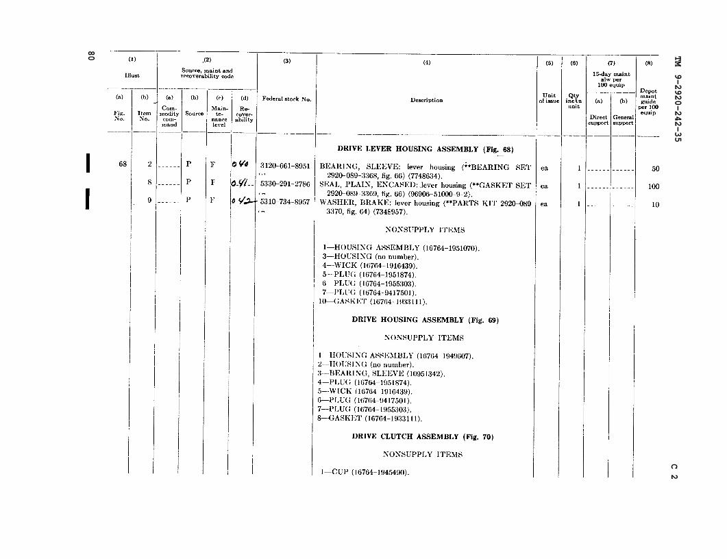
Fig. 68
fig. 66
fig. 64
Fig. 69
Fig. 70
TM 9-2920-242-35
C 2
80
LOGSA
3120-661-8951
LOGSA
5330-291-2786
LOGSA
5310-734-8957

C 1, TM 9-2920-242-35
Figure 68. Drive lever housing assembly–exploded view.
81

SEE FIGURE 66
C 1, TM 9-2920-242-35
Figure 69. Drive housing assembly–exploded view.
82

C 2 TM 9-2920-242-35
Figure 70. Drive clutch assembly–exploded view.
83

Fig. 71
Fig N
o. 70
TM 9-2920-242-35
C 2
84
LOGSA
5330-719-5470

C 1, TM 9-2920-242-35
Figure 71. Frame assembly–exploded view.
85

C 1, T
M 9-2920-242-35
86

C 1, TM 9-2920-242-35
STOCK NUMBER INDEX
(3)
Illustration
(3)
Illustration
(1) (2) (1)
Federal 8tock No.
—— . . .._ —___ —__
5306-783-51885306-822-21205310-209-53095310-262-47535310-734-8957
5330-050-12185330-291-2786
5330-579-7544
5330-584-02655330-719-57405340-282-16685340-715-11525977-786-95645877-869-0439
(2)
-— ---(a)
Fig.No.
-—. —
6464666664686666686366667166646663
..—(b)
I~om
.—— —
1.11.21514
1.39
------8
16------..-8.11.4
120
Federal etook No.
.————— —— -
Part N>. (d
F#.
(b)
Itfom
Part No.
2920-089-33672920-089-33682920-089-33692920-089-33702920-226-65452920-287-89432920-446-75162920-758-99582920-777-71662920-807-24082920-812-01962920-839-18642920-973-15593120-661-8951
570270657027075702708570270910911018-1838068377486358737874873787687378777748643774863787122417748634
96906-35304-896906-35223-45
63666664
166--
ii636363
66686366
1821
---8.2------196
1.21.3------
21316
7748639774863896906-35338-2375291877348957
96906-28775-01096906-51000-9-2
96906-28775-243
96906-28775-01216764-192245796906-35648-696906-16624-103787378755702705
5305-584-79445305-638-3358
I
(3)
Illustration
PART NUMBER INDEX
(2) (3) (1)
Illustration
(2)(1)
Part No.
.——(a)
Fi:
-—
6363666664666468
71666668
636464636365667164
Part No.
.—-—(a)
F&.
-——
6767666766
6i
iii6363646666691
67706366
6767
-——(b)
Ite!a
----
----8.2
----2.1----20.1----
1196
----
----
------------
138.1
------------
Federal stock No. (b) Federal stock No.
It&m
--——— —.———- ———————
5977-869-04392920-089-33672920-089-33682920-089-33692920-0S9 3370-------------5310-734-8957
_—— ——_———
570270557027065702707570270857027~73489197348957
201821
2.41.3
9
83332748333310838068383932938665Q2587122418737873873787487378758737876873787710951331
-------.------------------2920-287-8943
-------------2920-973-1559-------------2920-758-9558597.7-786-95642920-777-71662920-807-2408-------------
7348958737322575291877748634
-------------5310-262-47533120-661-8951
2920-446-75162920-839-18645306-822-21205306-783-5188-------------2920-812-0196---_--.---.--
----14
----2
7748635774863777486387743639
10951342 -_-----------1.31.21.11.41.2
10911018-116764-45343516764-81241096906-35304-896906-35648-616764-184063316764-187484716764-1909523
29’’0-226-6545--------------------------774!3641
77486438327326
5305-584-79445340-282-1668----. . . . . . . . . . . . .-------------
8327432 ------------- ---- -------------
8 7

C 1, TM 9-2920-242-35
(3) Illustration
(3) Illustration
(1) Part No.
(2) Federal stock No.
(a) Fig. No.
(b) Item No.
(1) Part No.
(2) Federal stock No.
(a) Fig. No.
(b) Item No.
16764-1914640 16764-1914644 16764-1915536 16764-1915716 16764-1915717 16764-1915718 16764-1916439
16764-1918690 16764-1922457 16764-1931673 16764-1932033 16764-1933111
16764-1934478 16764-1936466 16764-1942969
16764-1943238 16764-1943242 16764-1944656 16764-1944841 16764-1946475 16764-1945484 16764-1945490 16764-1945496 16764-1946842 16764-1946881 16764-1948507 16764-1948516 16764-1948519 16764-1948520 16764-1948522 16764-1948526 16764-1948529 16764-1948606 16764-1948656 16764-1948659 16764-1948661 16764-1949606 16764-1949607 16764-1949619 16764-1950111 16764-1950145 16764-1951069 16764-1951070 16764-1951073
16764-1951874
………………… ………………… ………………… ………………… ………………… ………………… …………………
………………… 5330-719-5740
………………… ………………… …………………
………………… ………………… …………………
………………… ………………… ………………… ………………… ………………… ………………… ………………… ………………… ………………… ………………… ………………… ………………… ………………… ………………… ………………… ………………… ………………… ………………… ………………… ………………… ………………… ………………… ………………… ………………… ………………… ………………… …………………
…………………
67 67 … … 65 65 66 68 69 66 71 65 70 66 68 69 71 … 65 66 70 70 67 65 64 64 70 71 70 67 71 67 … … … … 64 70 65 65 65 64 69 64 … … 64 68 … 66 68 69
… … … … … … …
2.3 … … … … … … … … 2.2 … … … … … … … … … … … … … … … … … … … … … … … … … … … …
16764-1953236 16764-1953242 16764-1953244 16764-1954861 16764-1955303
16764-1955990 16764-1956985 16764-1957177 16764-1957184 16764-1957264 16764-1957349 16764-1957437 16764-1959269 16764-1962047 16764-1962048 16764-1964294 16764-1964839 16764-1964847 16764-1964849 16764-1964951 16764-1965093 16764-1965419 16764-1965421 16764-1966412 16764-1966451 16764-9412305 16764-9413509
16764-9414418
16764-9417501
16764-9421427
96906-35223-45 96906-35338-23 96906-35338-25 96906-51000-9-2
96906-28775-010 96906-28775-012 96906-28775-243
96906-16624-1037
………………… ………………… ………………… ………………… …………………
………………… ………………… ………………… ………………… ………………… ………………… ………………… ………………… ………………… ………………… ………………… ………………… ………………… ………………… ………………… ………………… ………………… ………………… ………………… ………………… ………………… ………………… …………………
………………… ………………… ………………… 5305-638-3358 5310-209-5309 ………………… 5330-291-2786 5330-050-1218 5330-584-0265 5330-579-7544 5340-715-1152
… … … … 66 68 69 71 70 70 70 70 70 70 70 67 67 71 … 70 70 70 67 71 71 70 70 64 65 66 65 66 71 68 69 65 66 71 66 66 63 66 68 66 66 63 66 64
… … … … …
… … … … … … … … … … … … … … … … … … … … …
…
…
…
16 15 14 … 3 … … 16
14
88

C 3, TM 9-2920-242-35
INDEX
Paragraph
Adjusting drive clutch pinionclearance . . . . . . . . . . . . . . . . . . . . . . . . . . . .36
Allocation . . . . . . . . . . . . . . . . . . . . . . . . . ...2Appendix I, references .. . . . . . . . . . . . . . ..lbAppendix II, Repair parts list . . . . . . . . . . ..1cArmature:
Checking eccentricity . . . . . . . . . . . . . . ..26dCleaning . . . . . . . . . . . . . . . . . . . . . . . . ...25cDescription . . . . . . . . . . . . . . . . . . . . . ...4aInspection . . . . . . . . . . . . . . . . . . . . . . . .26dInstallation . . . . . . . . . . . . . . . . . . . . . . . .35cRemoval . . . . . . . . . . . . . . . . . . . . . . . . . ..l8Repair . . . . . . . . . . . . . . . . . . . . . . . . . . ..27dResurfacing . . . . . . . . . . . . . . . . . . . . . . ..27dTesting for grounds . . . . . . . . . . . . . . . ..26dTesting for shorts . . . . . . . . . . . . . . . . . ..26dUndercutting mica . . . . . . . . . . . . . . . . . .27cWear limits . . . . . . . . . . . . . . . . . . . . . . . .41
Armature Spacer. (See Spacer,armature. )
Assembly, general procedures.. . . . . . . . ...28Bearing, commutator end plate:
General maintenanceinstructions . . . . . . . . . . . . . . . . . . . . ..24d, e
Inspection . . . . . . . . . . . . . . . . . . . . . . . ..26bInstallation . . . . . . . . . . . . . . . . . . . . . ..33bRemova l . . . . . . . . . . . . . . . . . . . . . . . ...*Repair . . . . . . . . . . . . . . . . . . . . . . . . . . . ..27bWear limits . . . . . . . . . . . . . . . . . . . . . . . .41c
Bearing drive clutch:General maintenance
instructions . . . . . . . . . . . . . . . . . . . . ..24d, einspection . . . . . . . . . . . . . . . . . . . . . . ...2&installation . . . . . . . . . . . . . . . . . . . . . ...32aRemoval . . . . . . . . . . . . . . . . . . . . . . . . . ..2lcRepair . . . . . . . . . . . . . . . . . . . . . . . . . . ..27eWear limits . . . . . . . . . . . . . . . . . . . . . . . .
Bearing drive housingGeneral maintenance
instructions . . . . . . . . . . . . . . . . . . . . ..24d,eInspection . . . . . . . . . . . . . . . . . . . . . . . ...26aInstallation . . . . . . . . . . . . . . . . . . . . . . ..34aRemoval . . . . . . . . . . . . . . . . . . . . . . . . . ..l9aRepair . . . . . . . . . . . . . . . . . . . . . . . . . . ..27aWear limits . . . . . . . . . . . . . . . . . . . . . . . .41e
Bearing, lever housingGeneral maintenance
instructions . . . . . . . . . . . . . . . . . . . . ..24d, eInspection . . . . . . . . . . . . . . . . . . . . . . . ..26fInstallation . . . . . . . . . . . . . . . . . . . . . . . .Removal, . . . . . . . . . . . . . . . . . . . . . . . . ..l9bRepair . . . . . . . . . . . . . . . . . . . . . . . . . . ..27eWear limits . . . . . . . . . . . . . . 41e
Bearing wicks (See Wick andspecific item. )
Page
40111
2423
1243810282824242744
30
232435141744
232633182844
232435142’746
232633142845
Paragraph Page
Bearings, sleeve (See specificitems. )
Bellows, rubber:Description . . . . . . . . . . . . . . . . . . . . . . . .4a 1Inspection . . . . . . . . . . . . . . . . . . . . . . . ..26g 26Installation . . . . . . . . . . . . . . . . . . . . . ...32c 33Removal . . . . . . . . . . . . . . . . . . . . . . . . . ..l9a 14
Boot. (See Bellows, rubber.)Brush holder assembly:
Assembly . . . . . . . . . . . . . . . . . . . . . . ..33a 35Cleaning . . . . . . . . . . . . . . . . . . . . . . . . . ..25d 23Description . . . . . . . . . . . . . . . . . . . . . ...4a 1Disassembly . . . . . . . . . . . . . . . . . . . . . ..20d 14Inspection . . . . . . . . . . . . . . . . . . . . . . . ..26c 24Repair . . . . . . . . . . . . . . . . . . . . . . . . . . . .27c 24
Brush springs. (See Springs,brush.)
Brushes, electrical eontact:Cleaning . . . . . . . . . . . . . . . . . . . . . . . . . ..25f 24Description . . . . . . . . . . . . . . . . . . . . . . . .4a 1Inspection . . . . . . . . . . . . . . . . . . . . . . ..26c 24Installation . . . . . . . . . . . . . . . . . . . . . ..33d 35Removal . . . . . . . . . . . . . . . . . . . . . . . . . ..20a 14Seating . . . . . . . . . . . . . . . . . . . . . . . . . . ..33d 35Wear limits . . . . . . . . . . . . . . . . . . . . ...41a 44
Cleaning . . . . . . . . . . . . . . . . . . . . . . . . . . . . . ..25 23Cleaning before disassembly . . . . . . . . . . ...16 10Clutch, drive
Assembly . . . . . . . . . . . . . . . . . . . . . . . ...32a 33Description . . . . . . . . . . . . . . . . . . . . . . . .4a 1Disassembly . . . . . . . . . . . . . . . . . . . . ..2lc 18Inspection . . . . . . . . . . . . . . . . . . . . . . . ..26c 24Installation . . . . . . . . . . . . . . . . . . . . . . . .32c 33Operation . . . . . . . . . . . . . . . . . . . . . . . . ..4b 1Removal . . . . . . . . . . . . . . . . . . . . . . . . . ..2la 18Repair . . . . . . . . . . . . . . . . . . . . . . . . . ..27e 29
Common tools and equipment . . . . . . . . . ...8 5Commutator:
Inspection . . . . . . . . . . . . . . . . . . . . . . . . . 26d 24Polishing . . . . . . . . . . . . . . . . . . . . . . . ..27c 27Resurfacing. ... . . . . . . . . . . . . . . . . . ..27c 27Undercutting mica . . . . . . . . . . . . . . . . . .27c 27Wear limits ... . . . . . . . . . . . . . . . . . ..41f 45
Commutator end plateassembly:
Assembly . . . . . . . . . . . . . . . . . . . . . . . ..33c 35Description ..., . . . . . . . . . . . . . . . . ...4a 1Disassembly .,. . . . . . . . . . . . . . . . . .20b 14Inspection . . . . . . . . . . . . . . . . . . . . . . ..26b 24Installation . . . . . . . . . . . . . . . . . . . . . ..33d 35Removal . . . . . . . . . . . . . . . . . . . . . . . ...20a 14Repair . . . . . . . . . . . . . . . . . ..27b 27
Index 1

C 3, TM 9-2920-242-35
ParagraphParagraph Page
Contact assembly, solenoidrelay:
Inspection . . . . . . . . . . . . . . . . . . . . . . . ..26hInstallation . . . . . . . . . . . . . . . . . . . . . . ..31aRemoval, . . . . . . . . . . . . . . . . . . . . . . . ...226
Improvised tools . . . . . . . . . . . . . . . 10Inspection:
Detailed . . . . . . . . . . . . . . . . . . . . . . . ...26General . . . . ...24
Installation of starter assembly . . . . . ...15
5
263121
242310
Data . . . . . . . . . . . . . . . . . . . . . . . . . . . . . . . . ..5Description . . . . . . . . . . . . . . . . . . . . . . . . ...4aDisassembly, general
procedures . . . . . . . . . . . . . . . . . . . . . . . . . ..17Drive clutch. (See Clutch,
drive.)Drive clutch spring. (SeeSpring, drive clutch.)Drive housing. (see Housing,
drive.)
Lead assembly, electrical:Installation . . . . . . . ..3%’Removal . . . . . . . . . . . . . . . . ...20a
Lever, shift:Description . . . . . . .4aInspection . . . . . . . . . . . ...269
Installation . . . . . . . . . . . . . . ..32cRemoval . . . . . . . . . . . . . . ...21aRepair . . . . . . . . . ..27gWear limits. . . .
3514
41
101
2633182943
Lever housing. (See Housing,lever.)
Lever shaft. (See Shaft, lever.)Lubrication. . 29
End plate, (See Commutator endplate.)
30
41
Field coils:Cleaning . . . . . . . . . . . . . . . . . . . . . . . . . .Description, . . . . . . . . . . . . . . . . . . . . . .Disconnecting brushconnections . . . . . . . . . . . . . . . . .
25b4 a
231
No-load test . . . . . . . . . . ..38
Oil seal. (See Seal, oil.)O p e r a t i o n . . . . . . . . . 4 b14
273022
1
120aInspection . . . . . . . . . . . . . . . . . . . . . . .Installation . . . . . . . . . . . . . . . . . . . . . .R e m o v a l . . . . . . . . . . . . . . . . . . . . . .
Forms, records, and reports . . . . . . . . . .Frame assembly
Assembly . . . . . . . . . . . . . . . . . . . . . . . . .Description . . . . . . . . . . . . . . . . . . . . . . .Disassembly . . . . . . . . . . . . . . . . . . . . . .Inspection . . . . . . . . . . . . . . . . . . . . . . .Repair . . . . . . . . . . . . . . . . . . . . . . . . . . .Testing field coils . . . . . . . . . . . . . . . . . .
26i3 02 3
Parts. .7Pinion block check.... . . . . . ...36Pinion clearance, adjusting . ..36Plunger solenoid:
Description . . . . . . .4a
54040.3
126331829
.3040.2326i
2 7 h2 6 f
301
22272927
Inspection. . . . . . . . . . . ...269Installation . . . . . . . ..32cRemoval. .21aRepair . . . . . . . . . . . ..27g
Pole shoes:Installation. .30Removal . . . . . . . . . 23
3022
Housing, drive:Assembly . . . . . . . . . . . . . . . . . . . . . . . ..34aDescription . . . . . . . . . . . . . . . . . . . . . . . .4aDisassembly. . . . . . . . . . . . . . . . ..l9bInspection . . . . . . . . . . . . . . . . . . . . . . . ..26aInstallation 34bR e m o v a l . . . . . . . . . 1 9Repair . . . . . . . . . . . . . . . . . . . . . . . . ..27a
Housing, lever:Assembly . . . . . . . . . . . . . . . . . . . . . . . . ..32bDescription . . . . . . . . . . . . . . . . . . . . . ..4aDisassembly . . . . . . . . . . . . . . . ..21bInspection . . . . . . . . . . . . . . . . . . . . . . . ..26fInstallation. . . . . . . . . . . . . . . . ...32cRemoval . . . . . . . . . . . ..2laRepair . . . . . . . . . . . . . . . . ..27f
351
1424351427
1Records . . . . . . . . . . . . . ..3Relay, solenoid. (See solenoid
relay. )Removal of starter assembly. . . . . . ...15Repair
Detailed instructions . . . . ...27General instructions . 24
10
2723
331
1826331829
Repair standards:General. . . . . . ...40Wear limits ..41
Replacement parts... . . . ...7
4344
51Reports . . . . . . . . . . . . . . 3
Rubber bellows. (See Bellows,rubber. )
Index 2

C 3, TM 9-2920-242-35
Paragraph
s c o p e 1Seal, oil:
General maintenanceinstructions 24bInstallation . . . .32bRemoval. . .21b
Shaft lever:Inspection . ..269Installation . . . . ..32cRemoval. . 270Repair . . . . . . . . 27gWear limits . . . . . . ..4lc
Shift lever. (See lever shift.)Sleeve bearings. (See Bearinga
and specific item. )Solenoid plunger. (See Plunger,
solenoid. )Solenoid relay:
Assembly . ..31aCleaning. . . . . . . ..25eDescription . . . . ...4aDisassembly. . .22bInspection . . . . . . . . . .26hInstallation .31bOperation . . . . . . . . . . . . ..4bRemoval. . . . . . . . . ...2%
Spacer, armature:Inspection . . . . . . . . . . . . . . . . . ..26jInstallation. . .Removal . . . . . . . . . . . . . . . ...20aWear limits . . . . . . . . . . . . . . . . . . ..4lb
Special tools and equipment. . . . . . . . . . ...9Sprags, drive clutch:
Description. . . . . . . . . . . . . . . ..4aInspection . . . . . . . . . . . . . . . .26eInstallation . . . . . . . . . . . ..32aLubrication . . . ...29Operation . . . . . . . . . . ..4bRemoval . . . . . . . . . .21c
Spring, drive clutch:Inspection . . . . . .26eInstallation. . . ..32aRemoval ..,. . . . . . . . . . . . . . . ..21cWear limits. . . . ..41g
Spring, solenoid plunger:Inspection, . . . . . . . . . . . . ..26gInstallation. . . . . . . . . . . . ..32cRemoval 21aWear limits. . ..41d
Springs, brush:Inspection . . . . ..26cInstallation. . . 33aRemoval. 20d
Page
1
233318
2633182944
3123
1212631
121
273514445
1263330
118
26331845
26331845
243514
Springs, brush — continued:Testing tension. . . . . . . . . . . . . . . . ...200Wear limits.. . ...41a
Table I Troubleshooting.... . . . . . . ...14Table 11 Lubrication i nstructions . . . . . . ...29Testing
Armature eccentricity. .26dArmature for grounds . . . . . . . . . . . . . ..26dArmature forshcrte . . . . . . . . . . . . . . ..26dBrush tension.. . . . ...20aField coils. . . . . . ..26iGeneral. . . . . . . . . ...37Solenoid relay . . . . ..26hStarter no-load test. . . . . . . . . ...38Starter waterproof test. . . . . . . ...39
Thrust washer, (See Washer,thrust.)
Tools and equipmentCommon . . . . . . . . . . . . . . . . . . . . . . ...8improvised . . . . . . . . . . . . . . ...10Special . . . . . . . . . . . . . . . . . . . . . . . ...9
Troubleshooting:General instructions and
procedures . . . . . . . . . . . . ...12Procedures . . . . . . ..13Purpose 11Table . . . . . . . . . . . . . . . . . . . . . . . . . . ...14
Undercutting mica. . . . . . . . . . . . . . . . . . . ..26c
Washer, thrust:Inspection . . . . . . . . . . . . . . . . . . . ...26jInstallation . . . . . . . . . . . . . . . . . . . ..33dRemoval . . . . . . . . . . . . . . . . . . . ..20aWear limits . . . . . . . . . . . . . . . . . . . . . ..41b
Waterproof test...... . . . . . . ...39Wear limits . . . . . . . . ...41Wick commutator end plate
Inspection, ... . . . . . . . . . . . . . . . . ..26bInstallation . . . . . . . ..33bLubrication . . . . . ...29Removal. . . . . . . ..20c
Wick, drive housing:Inspection . . . . . . . . . . . . . . . . ...26aInstallation. . . . . . . . . ...340Lubrication . . . . . . . . ...29Removal . . . ... . ..19a
Wick lever housing:Inspection . . . . . . . . . . . .26fI n s t a l l a t i o n . . . . . .Lubrication . .29Removal. .. .. .. 21b
Windings, field. ( See Field coils).
Page
1444
630
242424142742264243
555
6666
24
273514444344
24353014
24353014
26333018
Index 3

By Order of the Secretary of the Army:
Official:
J. C. LAMBERT,Major General, United States Army,
The Adjutant General.
Distribution:
Active Army:
DCSLOG (1)CNGB (1)US Army Maint Bd (6)USCONARC (3)USAMOCOM (2)USAWECOM (2)USAMUCOM (2)USAMICOM (2)USAECOM (2)USASMCOM (2)ARADCOM (2)ARADCOM Rgn (2)OS Maj Comd (2)OS Base Comd (2)LOGCOMD (2)Armies (3) except
Sixth (1)Corps (2)Div (2)Instl (1) except Ft Belvoir (7)
Ft Bragg (2) Ft Sill (6)Ft Meade (3) Ft Bliss (9)Ft Hood (7) Ft Sam Houston (7)
Svc Colleges (2)Br Svc Sch (2) except
Ord Sch (50)GENDEP (OS) (5)Ord Sec, GENDEP (OS) (5)Army Dep (1) except Black Hills,
Savanna (5) Tooele, San Jacinto (4)Sierra, Umatilla, Wingate (3)Letterkenny and Sioux (2)
Ord Dep (OS) (1)USAOSA (1)MAAG (2)
TM 9-2920-242-35
HAROLD K. JOHNSON,
dGeneral,
Unite States Army,Chief of Staff
USATAC (105)Ord PG (10)POE (2)USA Tml Comd (2)Army TM1 (2)Army Arsenal (5) except
Frankford (10) Joliet (4)Springfield Armory (2)Proc Dist (1) except
Cleveland (2) New York (5)Philadelphia (4) St Louis (3)Chicago (none)
Army Plants (5) exceptLake City (3 Radford (1)Ravenna (2) Kingsburg (none)
Mil Msn (1)Cen (2)Units org under fol TOE: (2 each)
9-79-129-259-269-279-659-669-679-769-1279-1379-1679-1979-3579-500 CA, CB29-55
NG: State AG (3) Units same as active Army except allowance is one copy to each unit.USAR: Same as active Army except allowance is one copy to each unit.For explanation of abbreviations used, see AR 320-50.


PIN :018449-000